

持续 50 年的生日提醒
组件和用品
 |
| × | 1 | |||
| × | 1 | ||||
| × | 1 | ||||
| × | 1 | ||||
| × | 1 | ||||
| × | 1 | ||||
| × | 1 | ||||
| × | 1 | ||||
| × | 1 | ||||
| × | 1 | ||||
| × | 1 | ||||
| × | 1 | ||||
 |
| × | 3 | |||
 |
| × | 2 |
必要的工具和机器
| ||||
 |
|
应用和在线服务
| ||||
 |
|
关于这个项目
是的,你没看错标题。你有没有忘记你的生日,你需要别人来提醒你?或者,如果您可以向您所爱的人赠送礼物,该设备会在他们生日那天祝他们 50 次 ?我不骗你,这个简单的 Arduino 驱动的生日闹钟 在 单个 CR2450 纽扣电池上运行 祝您的亲人(或您自己)50 岁生日快乐,在电池电量耗尽之前。
我想这是第一次有人像这样制作生日警报,因为我尝试搜索类似的项目但一无所获。这个项目也可以在我的个人项目网站上找到 - https://www.vishnumaiea.in/projects/hardware/birthday-reminder-device-that-will-run-for-50-years-on-a-coin-单元格
我将它作为 Hackaday Coin Cell Challenge 的一部分构建。这个生日警报的事情突然出现在我的脑海中,我开始研究我们可以在纽扣电池上运行多长时间。我以前从未使用过任何微控制器的睡眠模式。因此,我必须学习有关使 MCU 以极低的电流运行并节省单元的每一点能量的所有知识。这真的是一个挑战!我使用 ATmega168P 作为微控制器(实际上我修改了一个带有 ATmega168P 的 Arduino Nano,移除了所有不需要的组件,如稳压器、USB 桥接器等)并使用 Arduino IDE 开发固件。
时间和生日日期可以通过 USB 串行监视器进行编程。一旦设置了时间和闹钟,MCU 就会进入睡眠模式。每年当当前 RTC 时间与您的生日相匹配时,LED 将闪烁一分钟,并向串行监视器打印生日快乐消息。平均电流消耗约为 1.2 uAh(包括自放电),这使得它可以在 CR2450(540mAh)锂纽扣电池上运行超过 50 年。
特点
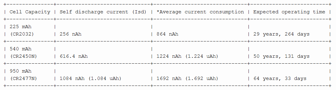
- 大约 1.22 uAh 包括电池自放电在内的平均电流消耗 (608 nA 不考虑自放电,由电流表测量,在电池 CR2450N 上)
- 不同类型锂纽扣电池的实际运行时间为:>29 CR2023 (225 mAh) 上的年数,>50 CR2450N (540 mAh) 和 >64 年 CR2477N (950 mAh) 上的年数。 [实际运行时间取决于电池在此期间的物理和化学健康状况]
- 可以通过 USB 上的任何串行监视器软件使用简单的命令设置和更新生日。
- 专用时间设置开关可让您随时设置、查看和更新时间。
- 时间的软件设置意味着,它可以通过在计算机上运行的应用程序进行非常准确的设置(基于Processing的时间设置/同步软件正在开发中)
- 开源 - 可以下载所有设计文件和软件代码以及详细的文档和高分辨率图像。
现在,我将引导您完成有关如何构建它的说明,并向您展示实际的电流消耗测试。
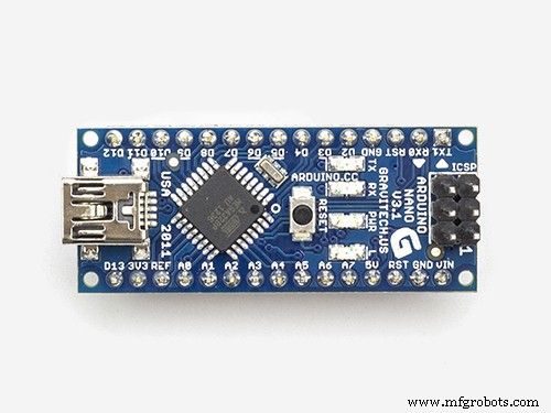
第 1 步:修改 Arduino Nano
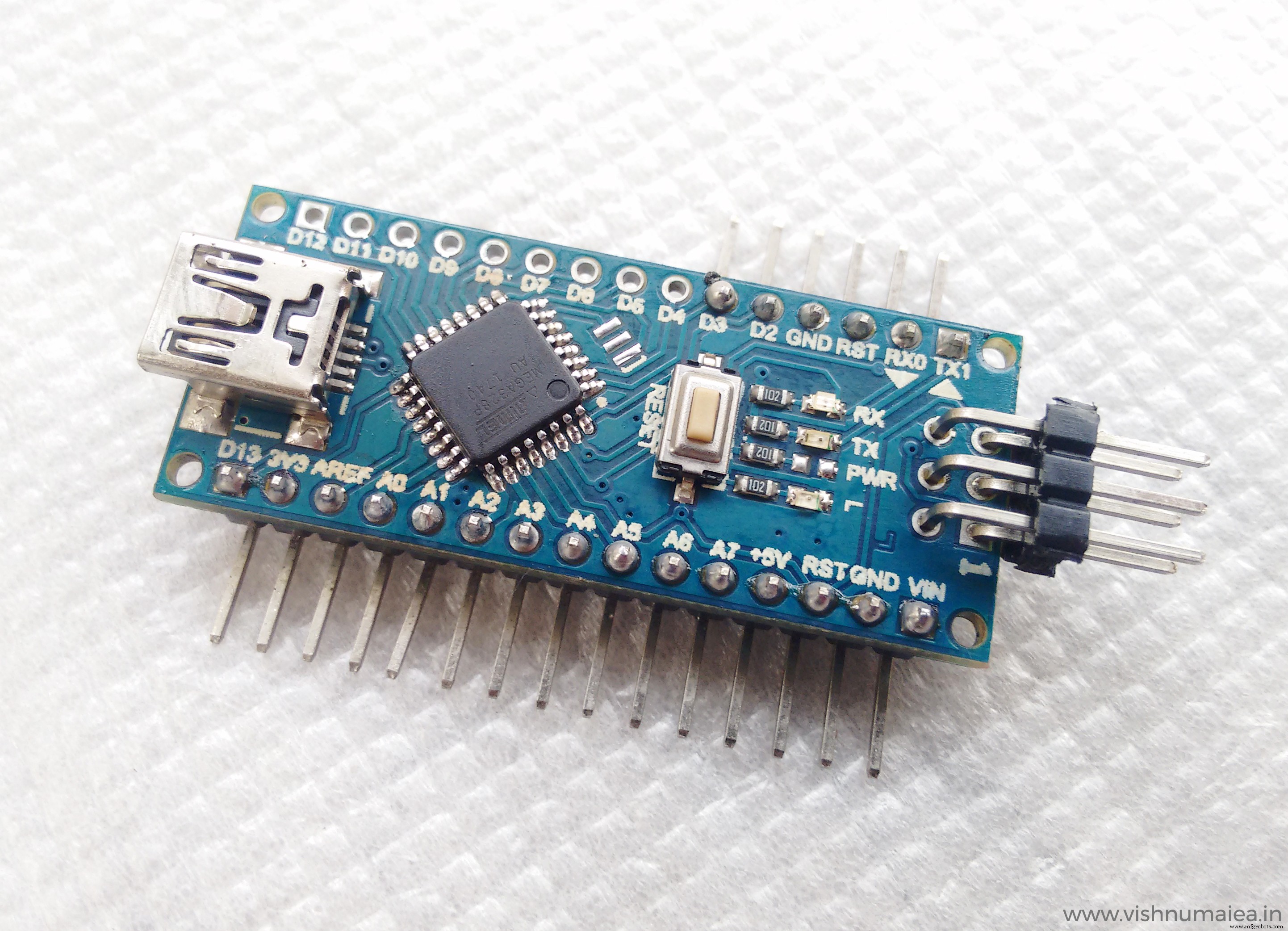
对于这个项目,您可以使用裸微控制器或使用 Arduino Nano 或 迷你 板。所需要的只是我们必须使用内部振荡器 (1MHz) 并在 1.8 - 5V 的完整工作范围内运行它。 CR2450 或类似的锂电池的标称电压为 3V,因此我们可以在不使用稳压器的情况下运行 MCU。中国克隆或 Nano 和 Mini 非常便宜,您可以以芯片的价格购买它们!我使用了这样一个具有 CH340G 的 Nano 克隆 作为 USB 到串行桥接器。下面是我用过的。
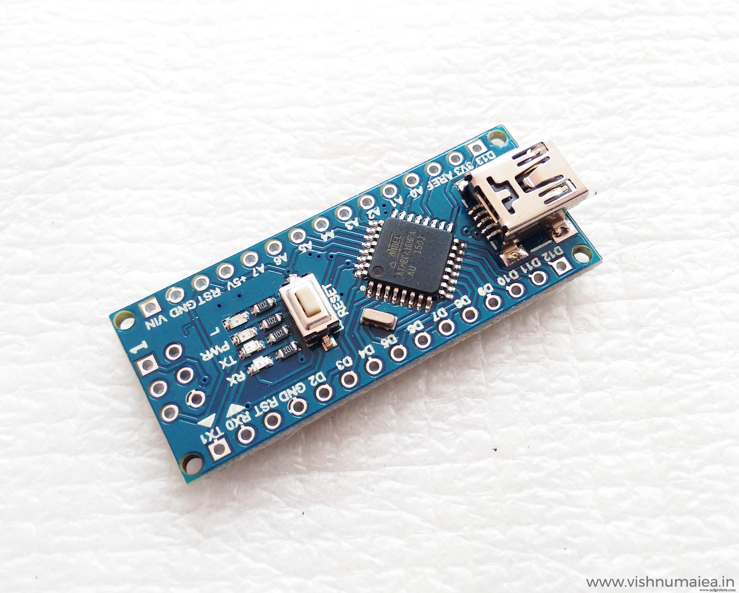
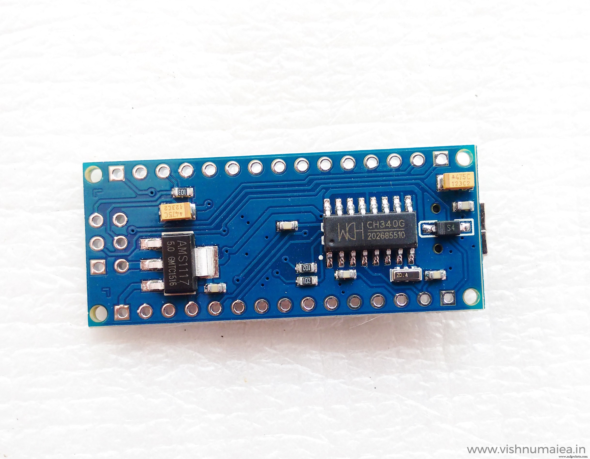
我有 ATmega168 和 328 版本。几年前我错误地购买了168版本(现在我找到了它的用途)。在这个特定的板中,您需要删除,
- USB 转串行桥接 IC,这里是 CH340G。
- 连接到 USB 5V 的肖特基二极管。
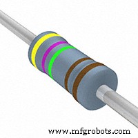
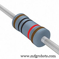
- 两个 1K 电阻连接到 CH340G 的 TX 和 RX 引脚。
- RX、TX 和 PWR LED (SMD)
- AMS1117 5V 稳压器。
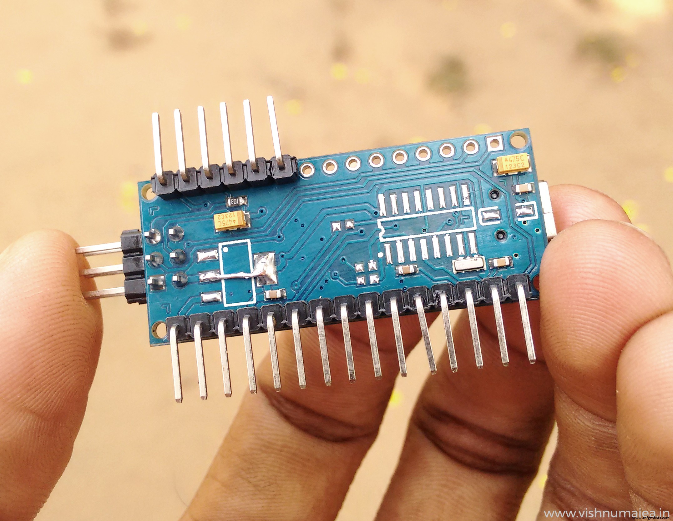
我使用引脚 13 上的 LED 进行调试并作为主闪光灯,因此我没有将其移除。无需移除电容器,因为它们有助于衰减噪声。移除稳压器后,您需要将稳压器的焊盘短路,如图所示。这是由于 PCB 设计中使用的布线。暂时不要移除 MCU 的晶体振荡器,因为我们需要它来更改熔丝位。 MCU 将具有默认的 Arduino 引导加载程序和保险丝设置,使其在外部 16MHz 晶振下运行。如果我们在设置保险丝之前移除晶体以使用内部 OSC,我们根本无法使用 ISP 编程器对芯片进行编程。下面是 Arduino Nano 的修改版本。
第 2 步:更改 ATmega168P 的保险丝位
通常,Arduino 板上的芯片将随 Arduino 引导加载程序和保险丝位一起提供。我们需要改变这一点,以便在低功耗模式下运行 MCU。为了实现这一点,我们需要,
- 使 MCU 以 1MHz 运行。我们可以启用内部振荡器以及“8 分频”位以从 8MHz 产生 1MHz 时钟。时钟速度越低,功耗就越小。我们不会在这里处理任何数字,因此 1MHz 已绰绰有余。
- 禁用掉电检测 (BOD) 模块。
- 禁用所有内部模块,例如 ADC、定时器等。我们将在软件中执行此操作。
- 禁用看门狗定时器 (WDT)。
- 使除引脚 13、2 和 3 之外的所有 IO 引脚输入和低电平。
以上是 ATmega168P 的保险丝设置。请注意,您需要 ATmega 芯片的“P”版本,因为它们具有微微功率功能。普通版本(非 P)不支持这些额外的省电模式。因此,请确保您获得 P 版本。您现在可能想知道为什么我使用 168 而不是 328。那是因为当我测试电路时,对于相同的代码,328 似乎消耗了大约 30uA,而我用于 168 的设置只消耗了大约 2uA。我不知道这是为什么。就像我之前说的,这是我第一次摆弄诸如深度睡眠之类的省电模式。所以我可能会错过一些东西。如果您对此有所了解,请在评论中告诉我。
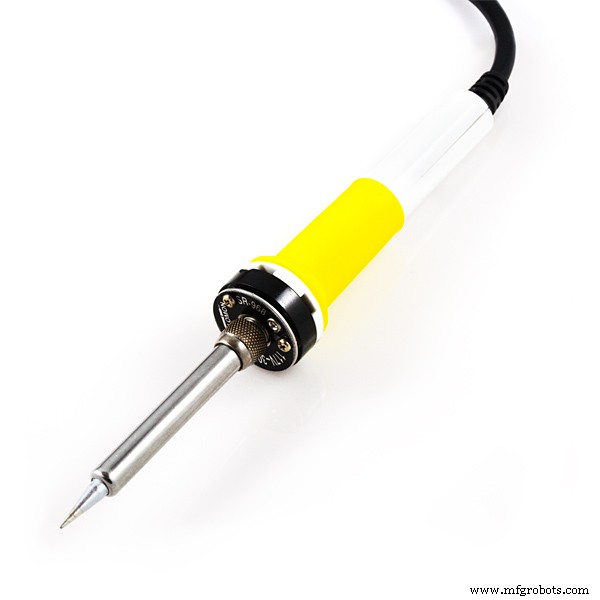
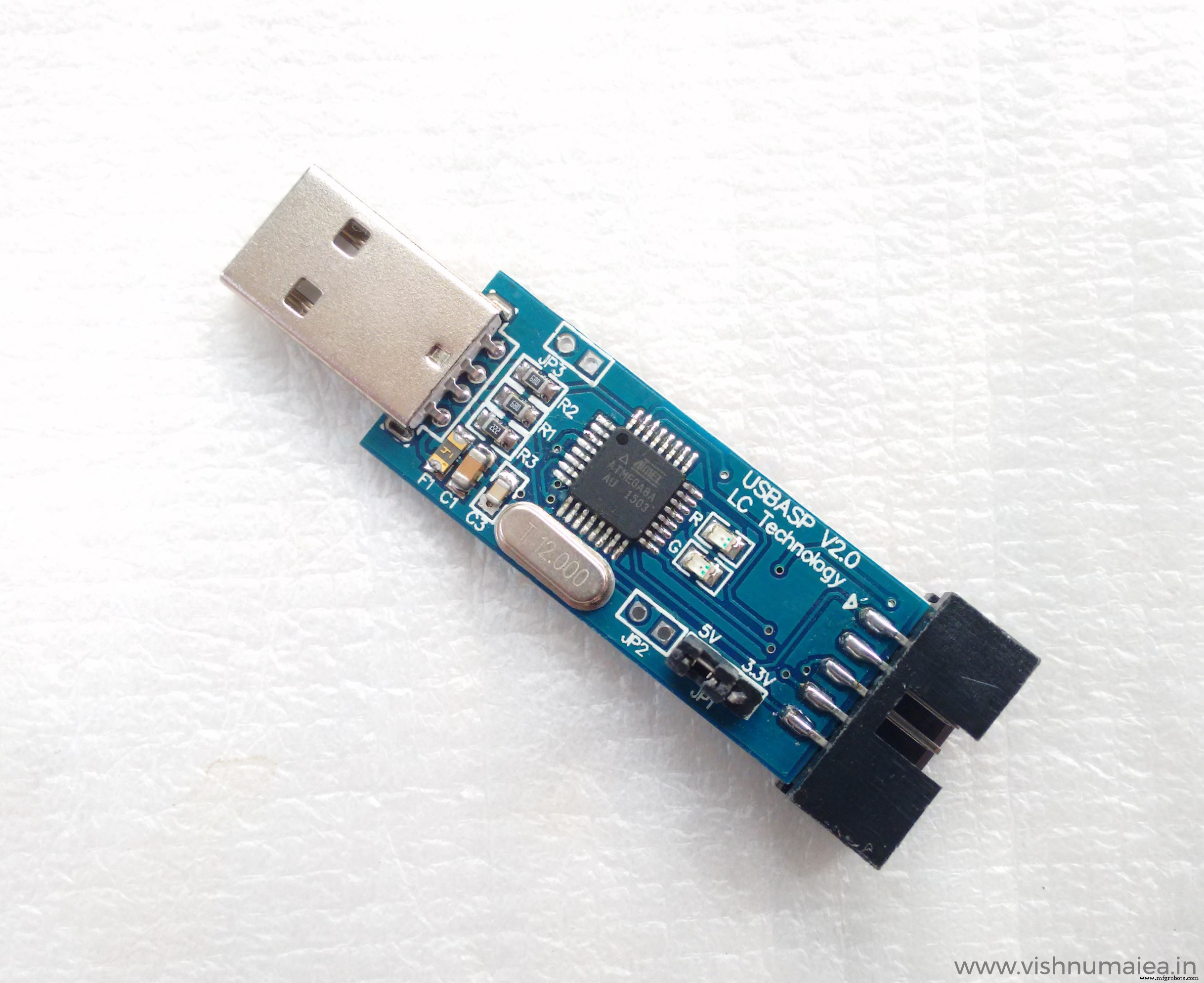
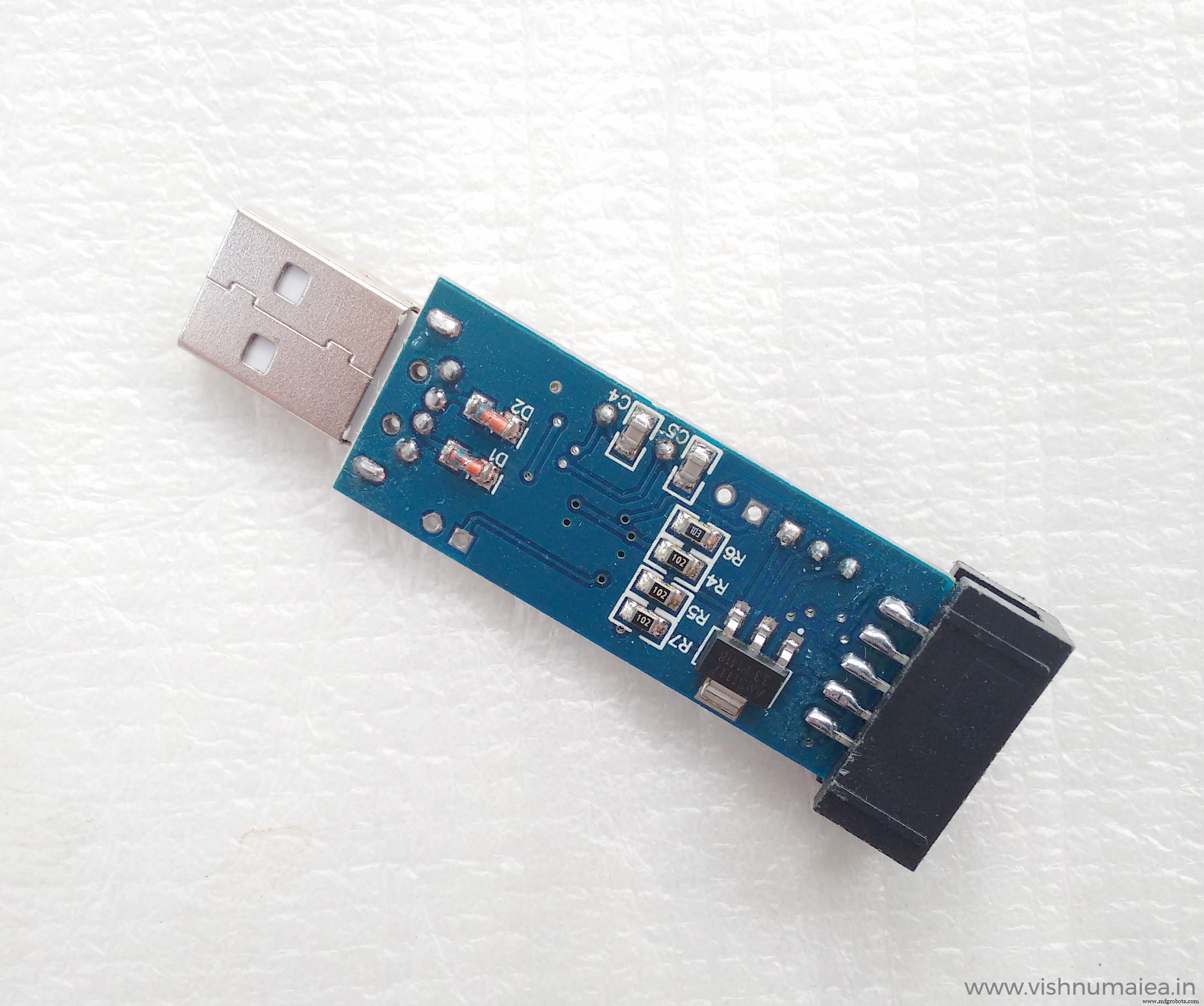
要更改熔丝位,我们需要一个 ISP 编程器。有很多ISP编程器和兼容软件。我使用了 USBasp 作为程序员和ProgISP 作为编程软件。我用的ATega168P-AU的芯片ID或签名是1E940B .这可能会根据您拥有的版本而改变。更改保险丝位:
- 将 USBasp 连接到 Nano。通常,USBasp 将有一个 10 针连接器,但 Nano 有 6 针 ISP 接头。所以我制作了一个简单的 10 针转 6 针适配器。您可能需要制作类似的东西或寻找电缆。
- 从列表中选择 MCU 型号并使用 RD 验证签名 按钮。
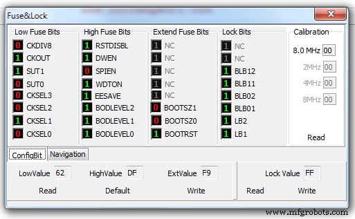
- 如下图所示设置复选框和熔丝位,并使用自动 按钮或写入 熔丝设置窗口上的按钮以更新熔丝位。

如果成功,将向控制台打印一条消息。从现在开始,您将需要 ISP 来刷新 MCU。下面是我用的USBasp。
第三步:编译上传
现在我们已经更改了微控制器的保险丝位,我们还需要将所做的更改告诉 Arduino 软件和编译器,以便我们可以在 Arduino IDE 中正确编译代码。我们如何做到这一点是通过在 "boards.txt" 中添加自定义板定义 位于 Arduino 安装目录中的文件,该目录通常位于
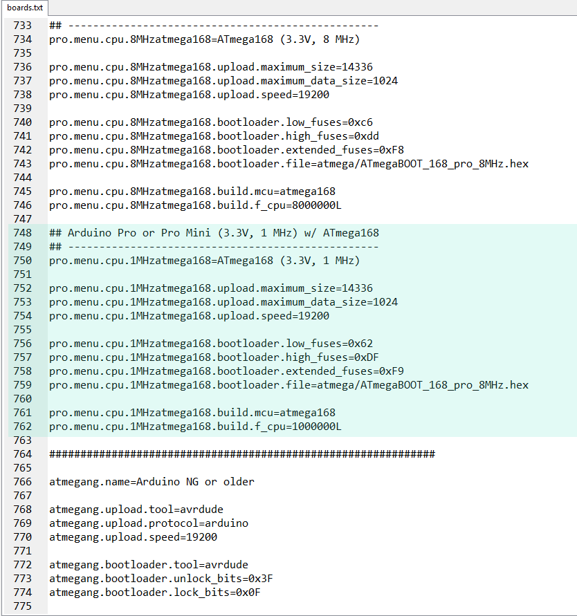
一旦我们找到了 board.txt 文件,您需要添加一个新的 Arduino Pro Mini 的自定义定义 木板。 655 行附近将是现有 Pro Mini 板定义的开始。板子会有很多版本。所以我们需要添加一个新的变体。向其中添加以下定义并保存。
## Arduino Pro 或 Pro Mini (3.3V, 1 MHz) w/ ATmega168 ## ------------------------- ------------------------- pro.menu.cpu.1MHzatmega168=ATmega168 (3.3V, 1 MHz) pro.menu.cpu.1MHzatmega168.upload .maximum_size=14336 pro.menu.cpu.1MHzatmega168.upload.maximum_data_size=1024 pro.menu.cpu.1MHzatmega168.upload.speed=19200 pro.menu.cpu.1MHzatmega168.bootloader.low_2cpuses60MHzatmega168.bootloader.low_2cpuses60MHzatmega. .bootloader.high_fuses=0xDF pro.menu.cpu.1MHzatmega168.bootloader.extended_fuses=0xF9 pro.menu.cpu.1MHzatmega168.bootloader.file=atmega/ATmegaBOOT_168_pro_8MHz.hex pro.menu.cpu168.bootloader.extended_fuses=0xF9 .menu.cpu.1MHzatmega168.build.f_cpu=1000000L 这是屏幕截图。
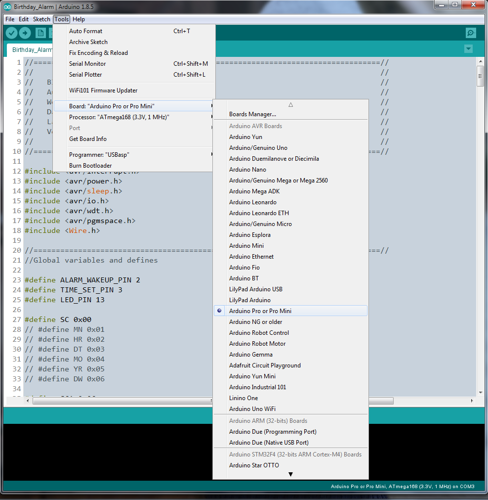
您需要在 Arduino 未运行时编辑 board.txt。保存新的 board.txt 文件并重新启动 Arduino IDE 后,您将在列表中看到我们刚刚添加的新板。看看下面的截图。

现在我们准备为我们的新板编译 Arduino 代码。因为我们没有使用 Arduino 引导加载程序 (BL) ,我们需要创建程序的十六进制文件,并使用USBasp和ProgISP刷写微控制器。我们可以使用“导出编译的二进制文件”来做到这一点 IDE 的 Sketch 菜单中的选项或点击 Ctrl + Alt + S .当我们这样做时,两个十六进制文件 (intel 格式)将在我们的草图所在的同一目录中创建。一个hex文件带BL,另一个不带BL。
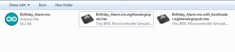
一旦我们有了十六进制文件,在 ProgISP 中选择 Load Flash 加载我们想要刷入 MCU 的十六进制文件的选项,然后点击 Auto 按钮。如果上传成功,会打印到ProgISP的控制台。
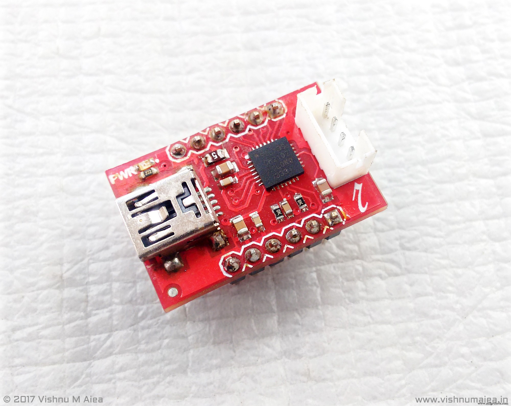
第 4 步:Intersil ISL1208 I2C RTC
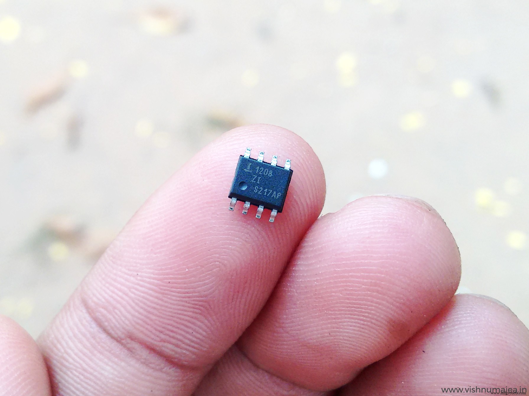
Intersil ISL1208 是一款具有I2C接口的低功耗RTC芯片。它使用外部 32.768 KHz 晶体来跟踪时间。具有月-日-时-分-秒报警寄存器。它在 VBAT 运行时仅消耗大约 400 nA,在 VDD 时最大消耗 1.2 uA。工作电压为 1.8V 至 5.5V。使其成为一个很好的候选者的是功耗和月份日期警报功能。像 DS1307 这样的普通 RTC 在闹钟寄存器中没有月份设置,否则我们就无法每年生成生日闹钟。它有一个中断输出引脚,将产生 250 毫秒 当前时间与闹钟日期和时间匹配时,低电平有效信号。我们将使用它从睡眠模式唤醒 MCU,我将在下面进一步解释。
ISL1208 的特点
- 实时时钟/日历
- -以小时、分钟和秒为单位跟踪时间
- - 星期几、日、月和年
- 15 个可选频率输出
- 单个闹钟
- - 可设置为秒、分钟、小时、星期几、日或月
- - 单事件或脉冲中断模式
- 自动备份到电池或超级电容器
- 电源故障检测
- 片上振荡器补偿
- 2 字节电池供电用户 SRAM
- I2C 接口
- - 400kHz 数据传输率
- 400nA 电池供电电流
- 与 ST M41Txx 和 Maxim DS13xx 器件相同的引脚
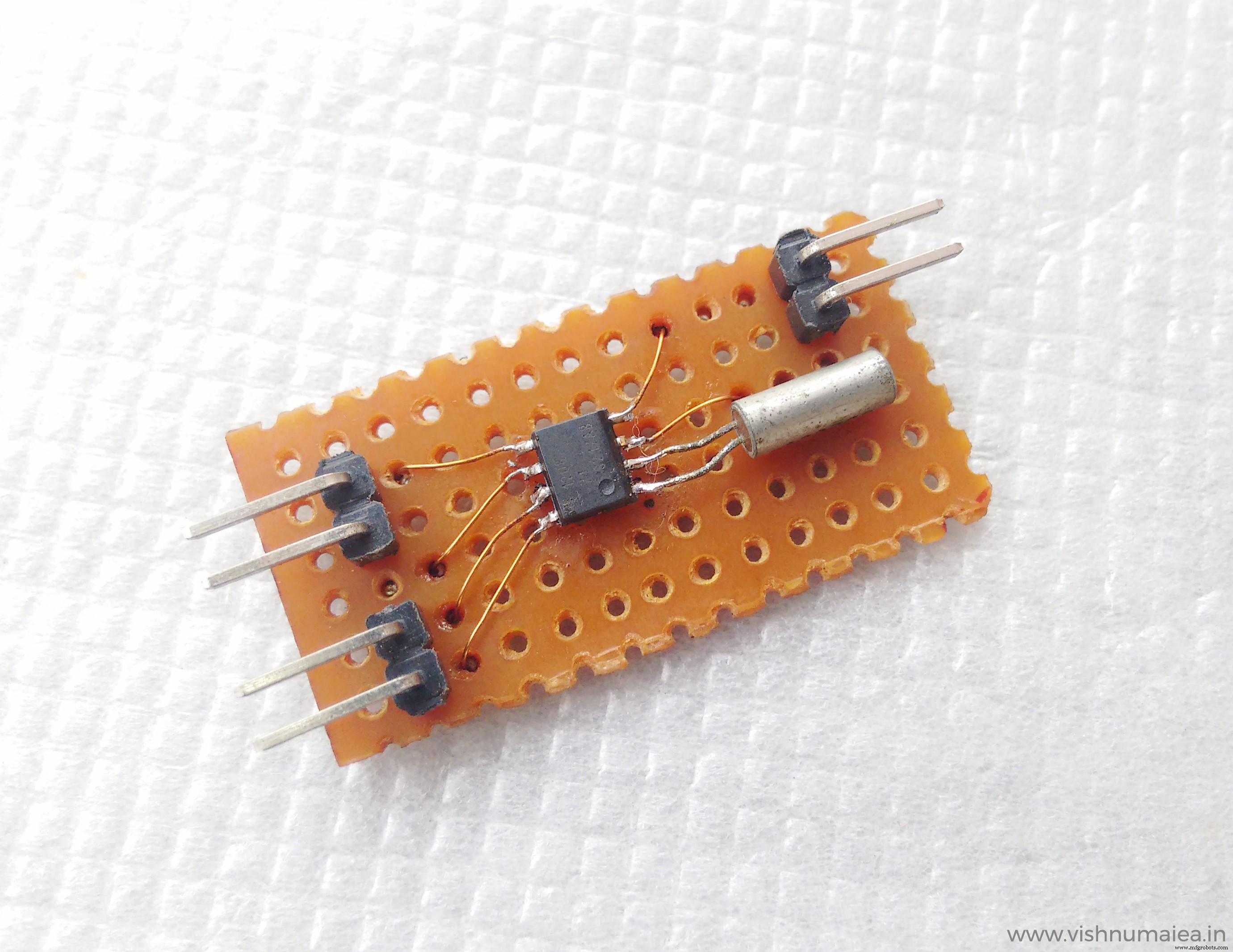
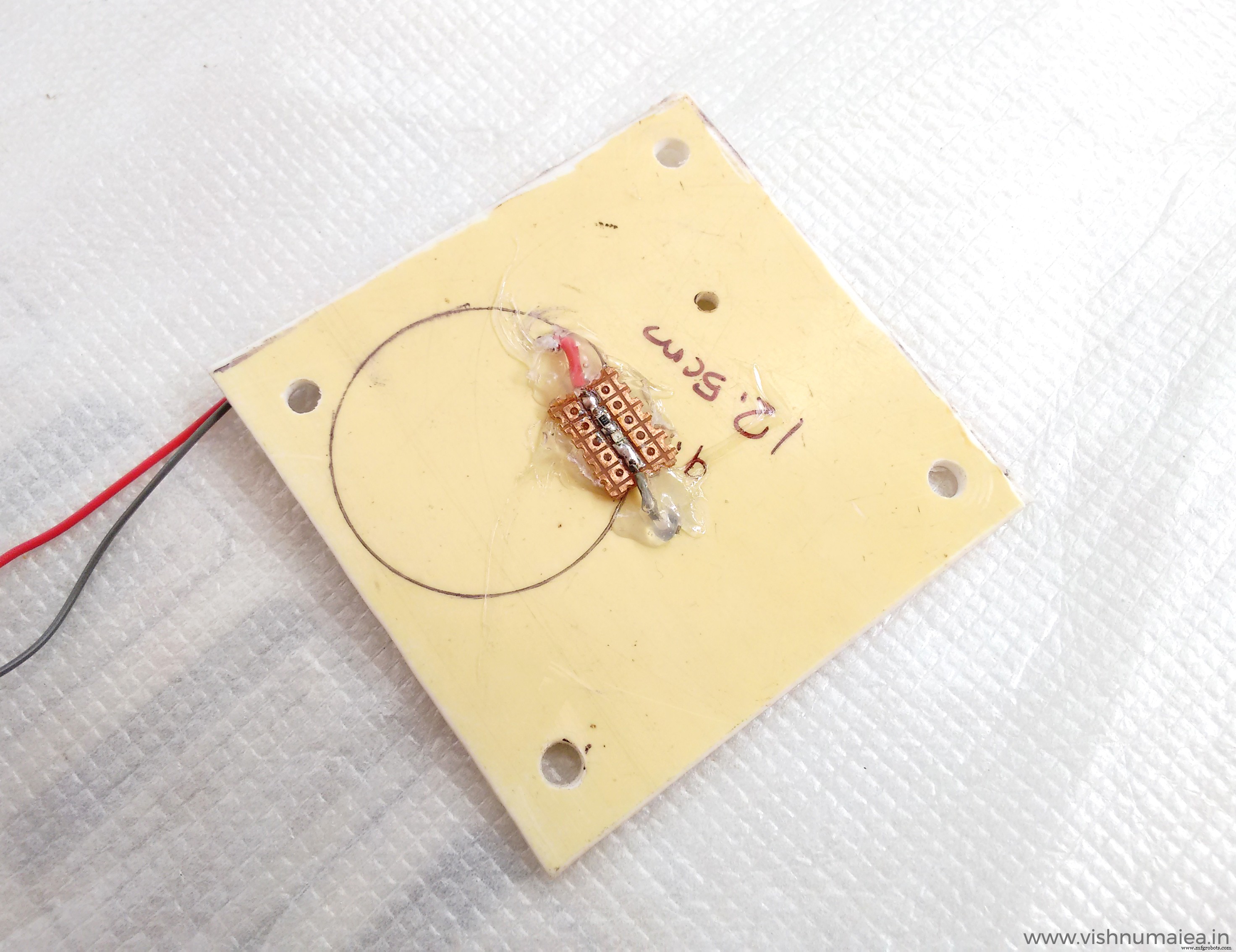
因为我有 ISL1208 的 SMD 版本,所以我必须制作一个分线板才能插入我的主板。下面是我做的。

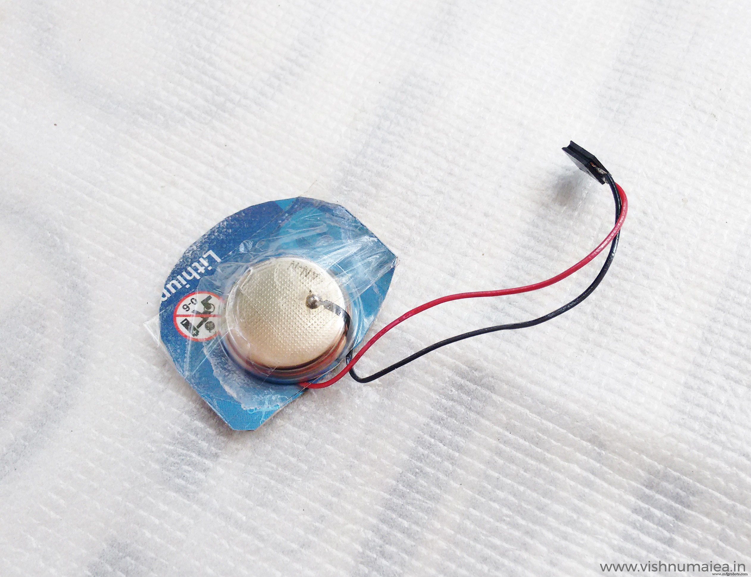
步骤 5:CR2450N 纽扣电池
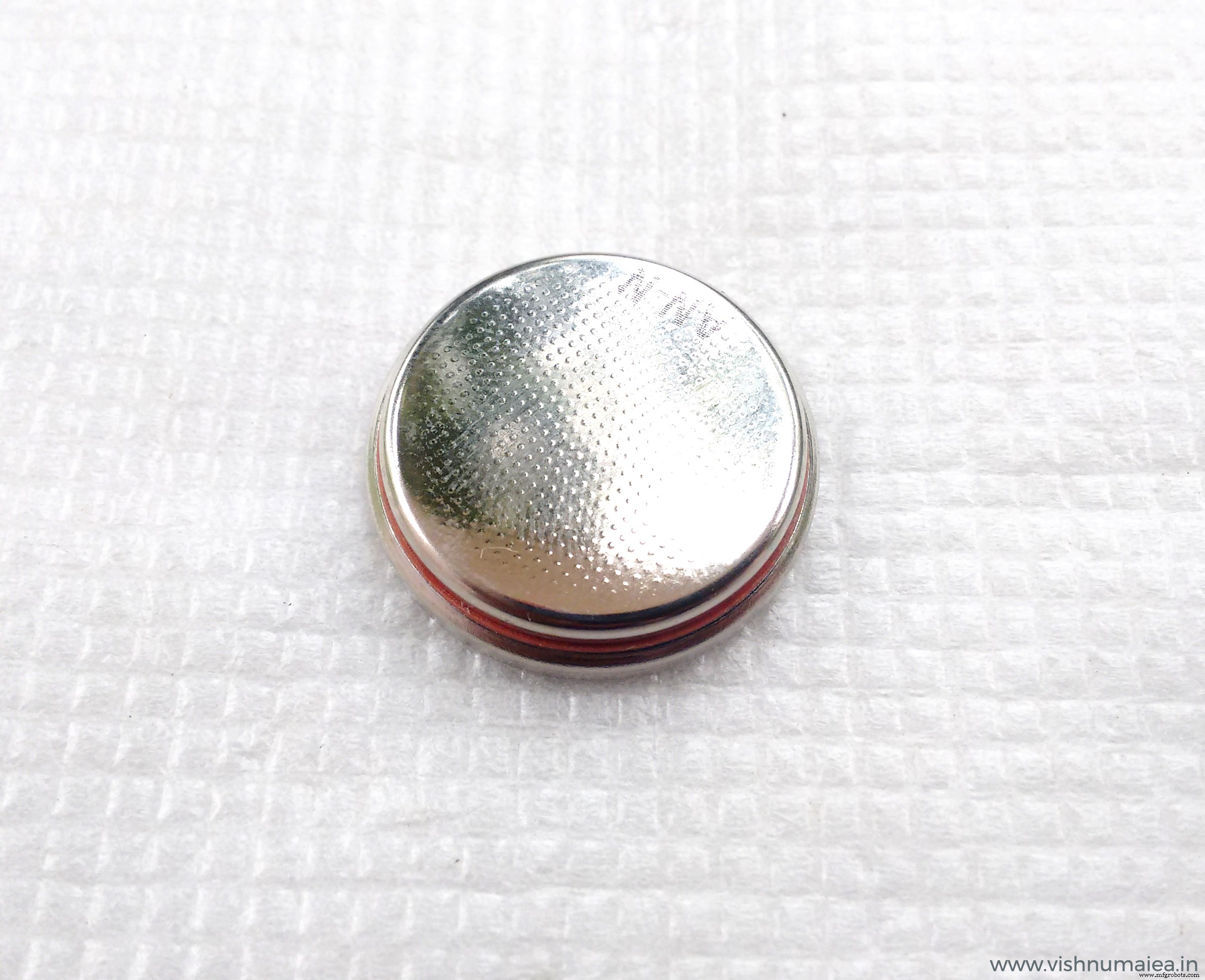
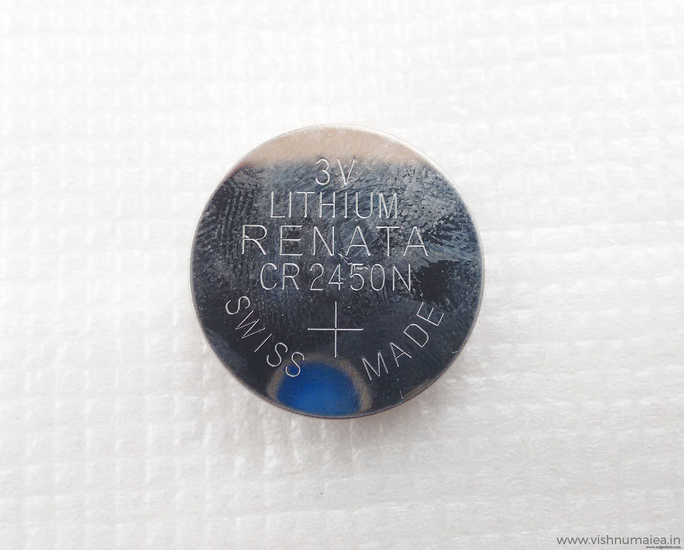
规格
- 化学体系 - Li / MnO2(根据 IEC 60086)
- 标称电压 - 3 V
- 额定容量 - 540 mAh
- 标准放电电流 - 0.8 mA
- 最大。续。放电电流 - 3.0 mA
- 平均重量 - 5.9 克
- 工作温度* - -40 - +85 °C
- 23°C 时的自放电 - <1% / 年
- 保质期 - 长达 10 年
第 6 步:示意图
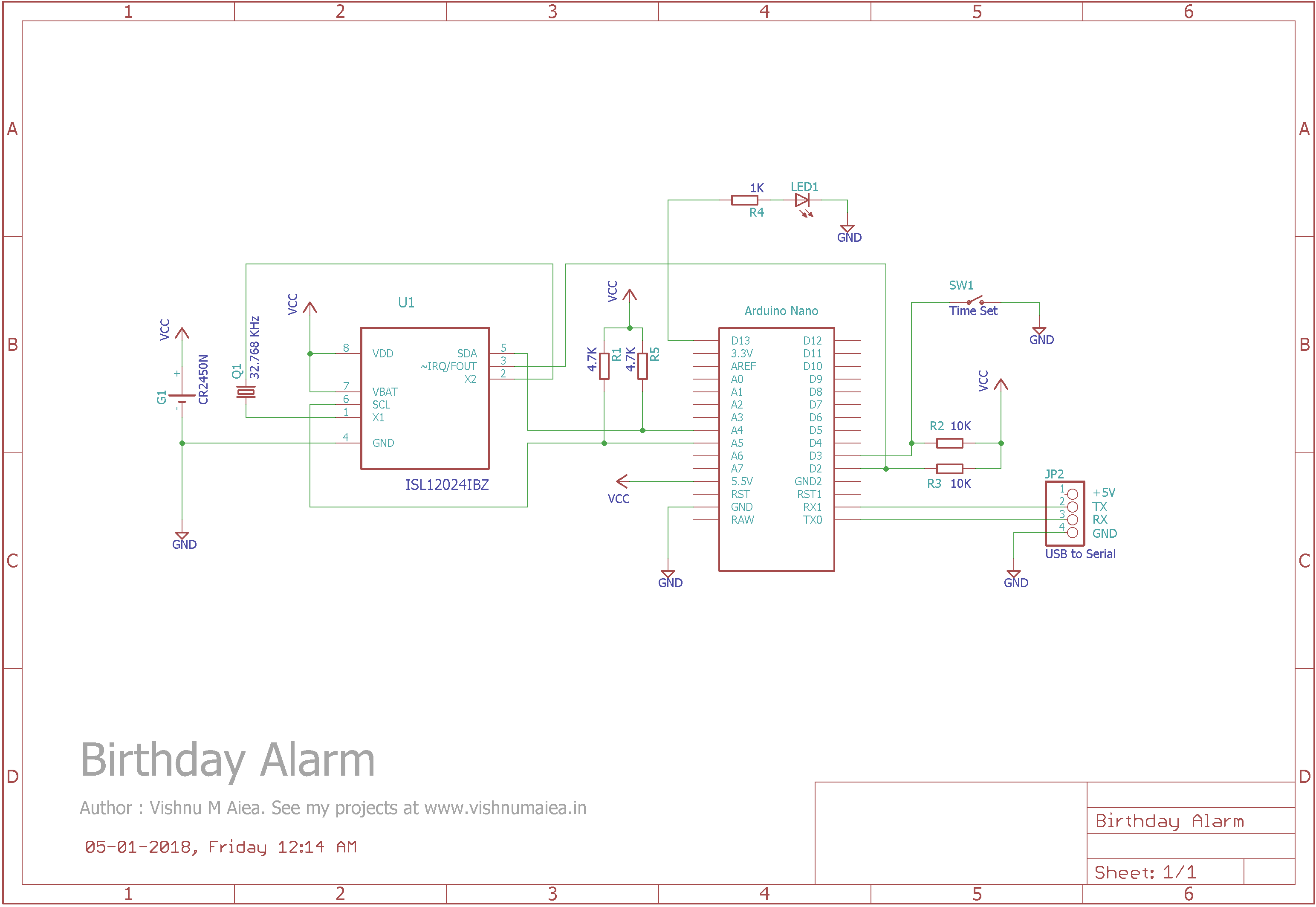
使用上面的示意图将模块焊接在穿孔板上。两个 4.7K 电阻是 I2C 上拉 .这些值的范围可以从 3.3K 到 5.6K 以上。 R2 和 R3 是中断引脚的上拉电阻。 Arduino Nano 有两个硬件中断引脚 - 数字引脚 3 和 2。数字引脚 2 将用于 RTC 的闹钟唤醒中断,数字引脚 3 将用于在您需要设置时间时唤醒 MCU。下面是CP2102 我使用的USB转串口模块。
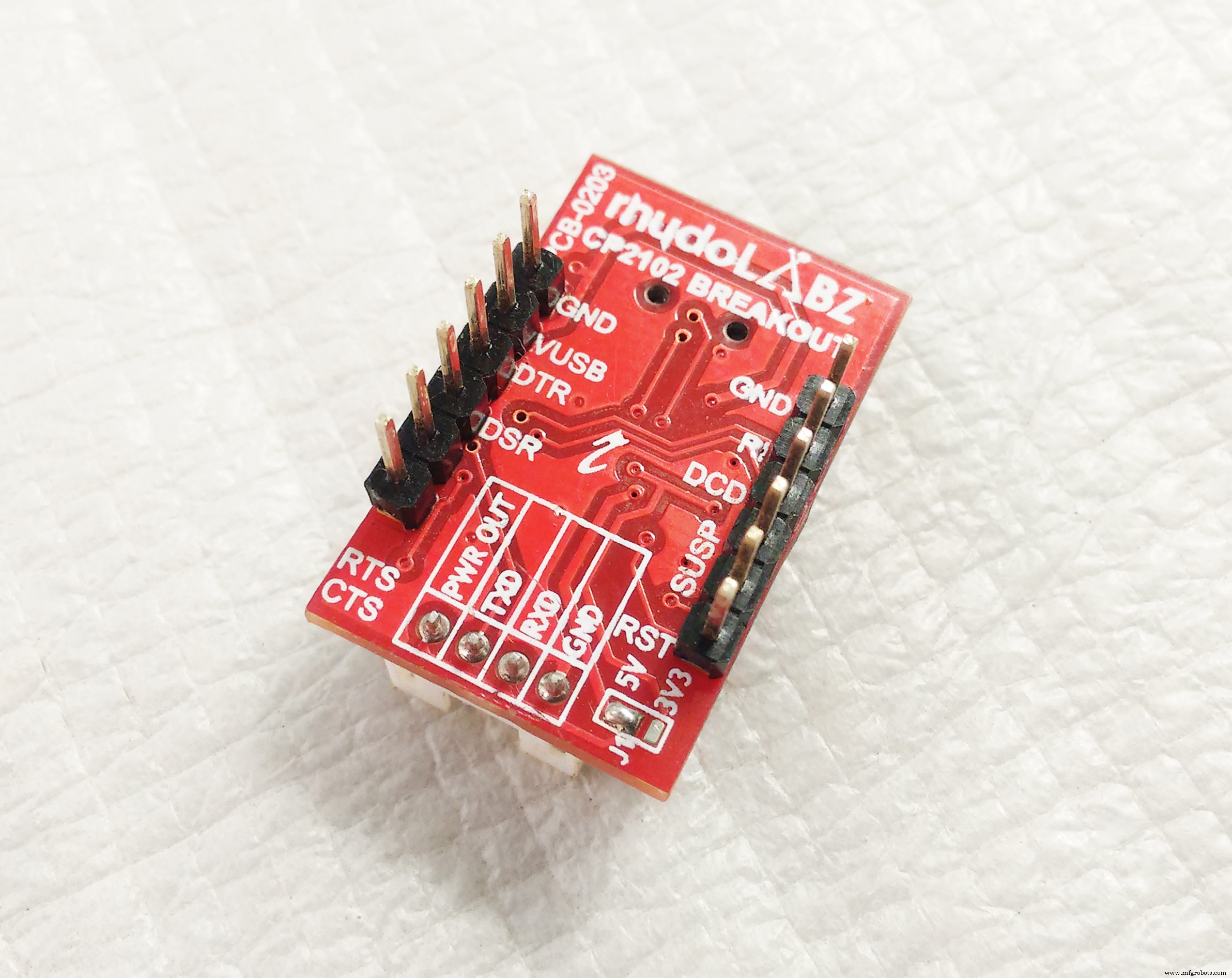
USB-to-Serial 模块将用于通过串行监视器进行通信。 CP2102 的 RX 和 TX 引脚分别连接 Nano 的 RX 和 TX 引脚。 请注意,您不应将 USB 的 +5V 连接到主 VCC 电压。
第 7 步:它是如何工作的?
该设备的工作实际上很安静简单。让我们看看主要算法是如何工作的,
- 通过串行监视器在 RTC 上设置当前时间。
- 在 RTC 上设置闹钟时间和日期。
- 通过禁用定时器和 ADC 等内部外设,MCU 在设置时间和闹钟后进入睡眠模式。
- 当当前时间与闹钟日期和时间(MM、DD、hh、mm、ss、p)匹配时,RTC 将生成中断并将 MCU 从睡眠中唤醒。
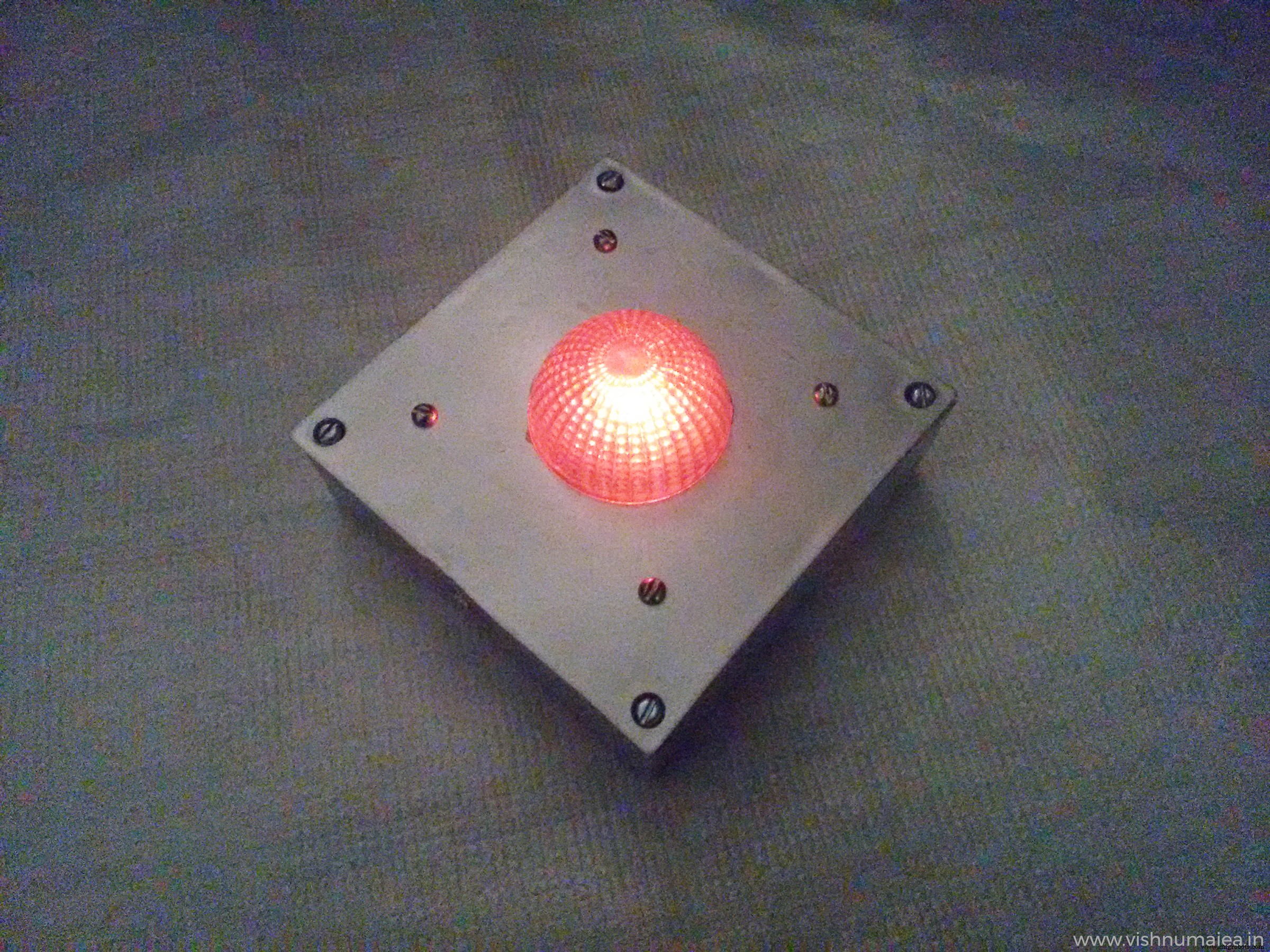
- 唤醒时,MCU 将启用所需的内部外围设备并向串行监视器打印生日快乐消息。它还以特定模式使圆顶内的 LED 闪烁。
- 祝您生日快乐后,MCU 将再次进入睡眠模式,并且只会在您明年生日那天醒来。
- 但是您可以通过转动时间更新开关来查看时间并在需要时进行更新 开启。
第一次上电时,所有 RTC 寄存器都将为零,并且在我们第一次写入其中任何一个之前它不会增加。要在 RTC 上设置时间,
- 打开时间更新开关(将数字引脚 3 连接到 GND)。如果不将引脚 3 拉低,我们就无法设置时间。
- 首先使用 USB 数据线将设备连接到您的计算机。将在您的 PC 上建立一个 COM 端口以进行通信。
- 在设备管理器中找到设备的 COM 端口。
- 使用设备的 COM 端口打开任何串行监视器软件或 Arduino 串行监视器。
MCU 会将以下消息打印到串行监视器。
串行建立。准备更新时间。 - 发送"t" 命令将打印当前时间,"a" 将打印闹钟日期和时间,以及 "c" 将取消时间设置操作,并在 6 秒后使 MCU 进入睡眠模式。
- 您需要以如下所示的格式发送当前时间,
TYYMMDDhhmmssp# 哪里:
- T =表示时间信息
- YY =年份的最低有效数字(例如,2018 年为 18,范围为 00 到 99)
- MM =月份(例如 01 代表一月,范围是 01 到 12)
- DD =日期(例如 24,范围是 01 到 31)
- 嗯 =小时(例如 06,12 小时格式的范围是 01 到 12)
- 毫米 =分钟(例如 55,范围是 00 到 59)
- ss =秒(例如 30,范围是 00 到 59)
- p =12 小时制(0 =上午,1 =下午)
- # =分隔符
例如,要设置时间和日期“08:35:12 AM, 05-01-2018”,我们应该发送:
T1801050835120# 到设备:
- T =表示时间信息
- 18 =2018 年
- 01 =一月
- 05 =日期
- 08 =小时
- 35 =分钟
- 12 =秒
- 0 =上午
- # =分隔符
如果操作成功,MCU 会将接收到的时间打印到控制台:
收到时间更新 =T1801050835120Date and Time is 8:35:12 AM, 5-1-18 如果您输入的时间字符串无效,将打印以下信息:
无效时间输入-<原始字符串>,<原始字符串长度> 一旦您成功设置了时间,只要有可用的电源,RTC 就会对其进行跟踪。您可以通过发送 "t" 来验证您刚刚设置的时间 命令。设置报警与此类似,只是数据格式不同。要设置闹钟,您需要将其发送为:
AMMDDhhmmssp# 哪里:
- A =表示报警信息
- MM =月
- DD =日期
- 嗯 =小时
- 毫米 =分钟
- ss =秒
- p =时间段(0 =上午,1 =下午)
- # =分隔符
请注意,警报字符串中没有年份信息,因为显然我们不需要它。 例如要设置我的生日“08:00:00 AM, 28-08”我需要发送:
A08240800000# 您可以随时使用命令 "a" 查看闹钟时间 .一旦设置了闹钟时间和日期,就可以让 MCU 进入睡眠状态。因此设备将打印以下消息:
一切就绪。请立即禁用时间设置引脚。 现在您需要关闭时间设置开关,即,将数字引脚 3 拉高(10K 上拉会这样做)。在您执行此操作之前,系统不会休眠。当时间设置开关关闭时,设备将在 6 秒后进入睡眠模式并在其前打印以下信息。
干得好! 6秒后入睡.. 这就是您设置时间和闹钟的方式。现在每当您需要查看时间或更新时间时,您可以打开定时器设置开关,系统将唤醒,建立串行通信并提示您发送时间。它会在醒来时打印以下消息,
串行建立。时间更新唤醒。准备更新时间。 如果您只是检查时间是否正确并且不想更改任何内容,请发送 "c" 命令取消操作并使系统再次进入睡眠状态。此时还需要关闭时间设置开关。
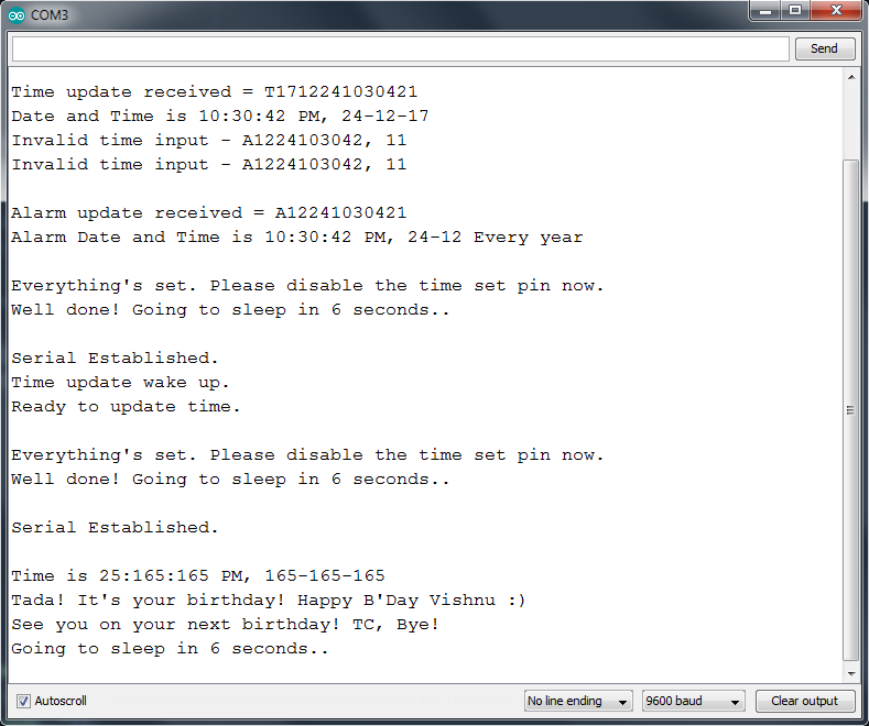
当当前时间与闹钟时间匹配时,即。你的生日,RTC 会产生一个 250mS 的中断信号到 Nano 的数字引脚 2。该信号将唤醒系统。醒来时,设备会知道今天是您的生日,并会建立串行通信(仅当您已连接 USB 时)并打印以下消息,
多田!这是你的生日!生日快乐 <你的名字> :) 下个生日见! TC。再见!6 秒后睡觉.. 它还会使连接到数字引脚 13 的 LED 闪烁。这是我测试系统时 Arduino 串行监视器的屏幕截图。
这就是您操作此设备的方式。要在代码级别理解这一点,请阅读下一节。
第 8 步:代码
这个项目是完全开源的,因此我已经在我的 GitHub 上发布了固件的源代码,地址是 https://github.com/vishnumaiea/Birthday-Alarm/ 在 MIT 许可下。您可以不受任何限制地自由改编、修改和重新分发。如果您想从修改后的项目中添加指向该项目的反向链接,我们将不胜感激。我已经对代码进行了彻底的注释,并尽可能直接进行。
我们在代码中总共有 13 个函数/过程。它们是:
1。 void setup() 这是Arduino的设置函数,它将初始化一切并设置ISl1208 RTC的配置寄存器。
2. void loop() 主循环函数。
3. void sleepNow()
该函数终止所有通信,禁用 MCU 的内部外设,将中断附加到数字引脚 3 和 2,并使系统进入深度睡眠模式。遇到任何中断,程序从 sleep_mode() 之后的那一行继续执行 .请注意,在恢复正常程序执行之前,MCU 将完成与中断引脚相关的中断服务例程,这些引脚是 alarmInterrupt() 和 timeUpdateInterrupt()
4. void alarmInterrupt() 与 INT0 关联的 ISR 数字引脚 2 上的中断。
5. void timeUpdateInterrupt() 与 INT1 关联的 ISR 数字引脚 3 上的中断。
6. void fetchTime()
fetchTime() 读取 RTC 的时间寄存器并将当前时间打印到控制台。
7.无效的闪烁LED() 使 LED 明显闪烁。
8.布尔建立串行() 借助USB转串口模块建立串口通信。
9. bool endSerial() 结束串行通信。
<代码>10。字节 bcdToDec(byte)
接受 BCD (Binary Coded Digits) 值并将其转换为相应的十进制值。我们需要这个是因为 RTC 寄存器只存储和接受 BCD 值。所以我们需要偶尔来回转换一下BCD。
11.字节 decToBcd(byte) 接受十进制值并将其转换为相应的 BCD 值。
12。 void printTime() 当 "t" 时读取 RTC 时间寄存器并将当前时间打印到控制台 收到命令。
13. void printAlarmTime() "a" 读取 RTC 报警寄存器并将报警时间和日期打印到控制台 收到命令。
第 9 步:测试
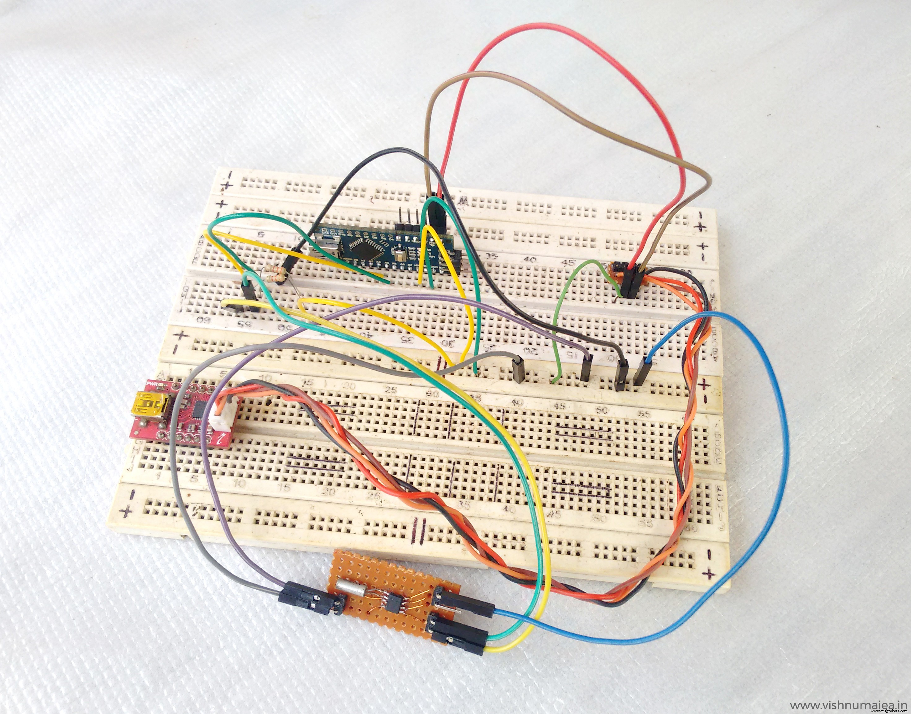
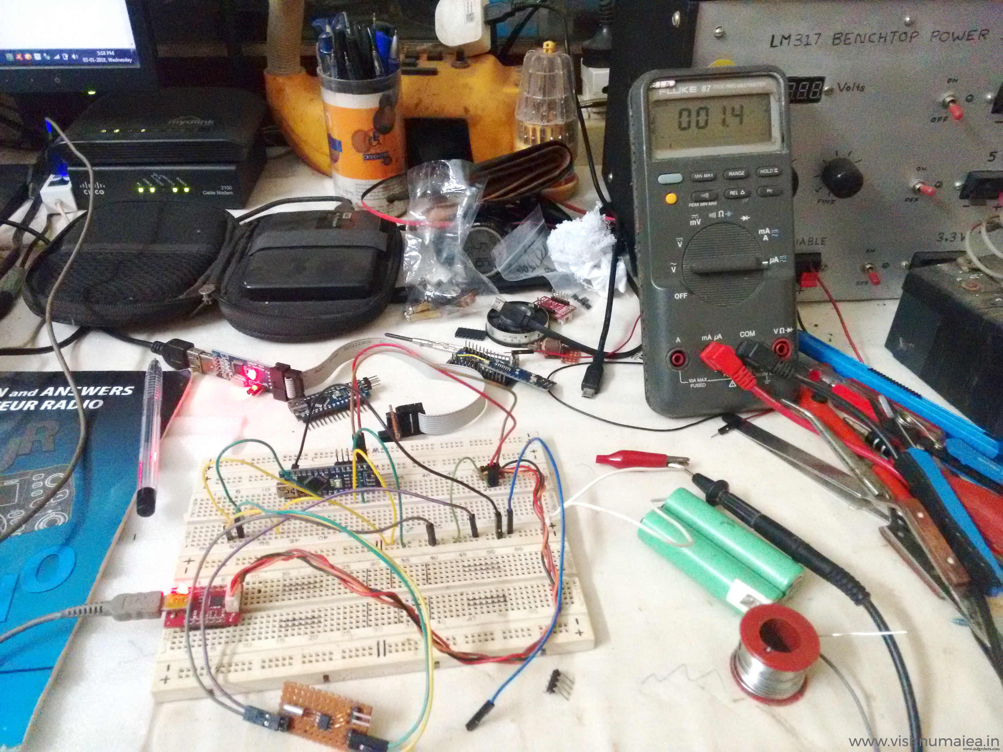
这将是这个项目中最有趣的部分,你会知道我是如何最终制造出一个在纽扣电池上运行 50 年的设备的! 我首先在面包板上对整个电路进行了原型设计,并最终确定了设计。我使用锂离子电池 (3.6V) 进行测试,以保存我全新的纽扣电池。我使用了我的 Fluke 87 True RMS 用于电流测量的万用表。它有 0.1 uA 微安级精度。
让我们看看如何将 Atmega168P 置于深度睡眠模式并大幅降低电流消耗。
noInterrupts(); //暂时禁用中断 set_sleep_mode(SLEEP_MODE_PWR_DOWN); // 选择我们喜欢的睡眠模式:sleep_enable(); // 设置睡眠使能 (SE) 位:ADCSRA =0; //禁用ADC power_all_disable(); //禁用所有模块 digitalWrite(LED_PIN, LOW); //关闭LED以指示睡眠中断(); //重新启用中断 sleep_mode(); //进入睡眠状态 正如我之前所说,这是我第一次在微控制器 (MCU) 中使用睡眠模式,因为我以前从未需要它。大多数与 AVR 睡眠模式相关的信息都来自此论坛主题和 AVR 库文档。
ATmega168P 有五种睡眠模式。
SLEEP_MODE_IDLE– 最省电SLEEP_MODE_ADCSLEEP_MODE_PWR_SAVESLEEP_MODE_STANDBYSLEEP_MODE_PWR_DOWN– 最省电
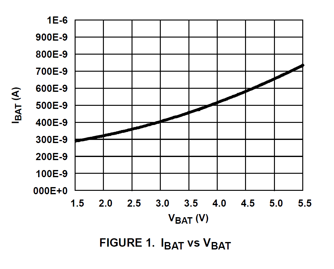
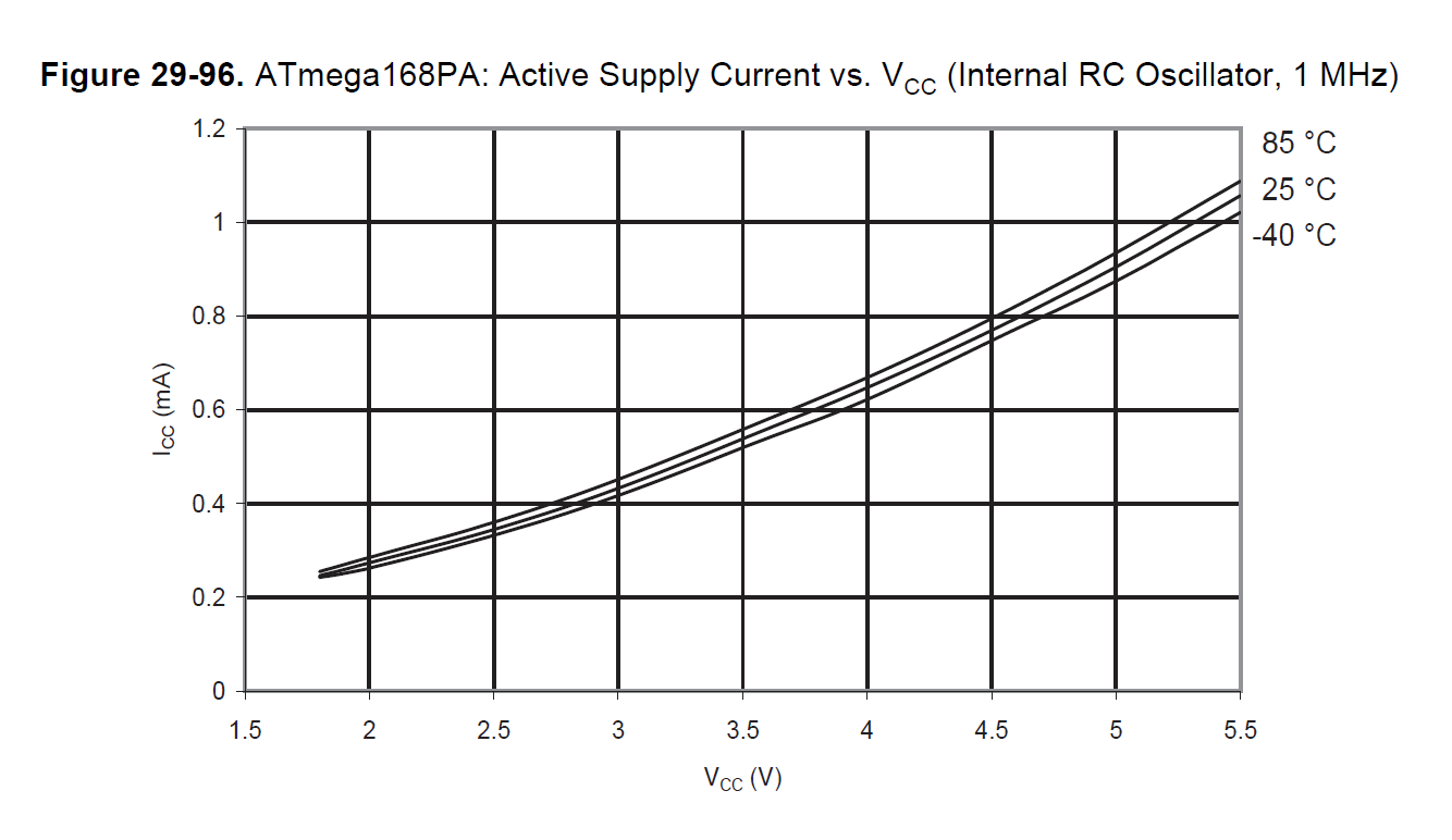
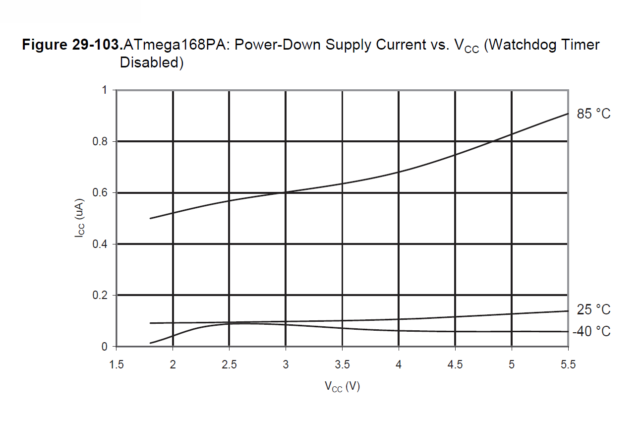
可以在此处和此视频中找到有关睡眠模式的更多信息。我们正在使用 SLEEP_MODE_PWR_DOWN 正如你在那里看到的那样。在此模式下,3.6V 下的电流消耗仅为 0.2 uA 左右 See the below graph from the ATmega168PA datasheet that shows the relation between active current vs supply voltage and power down current vs supply voltage.
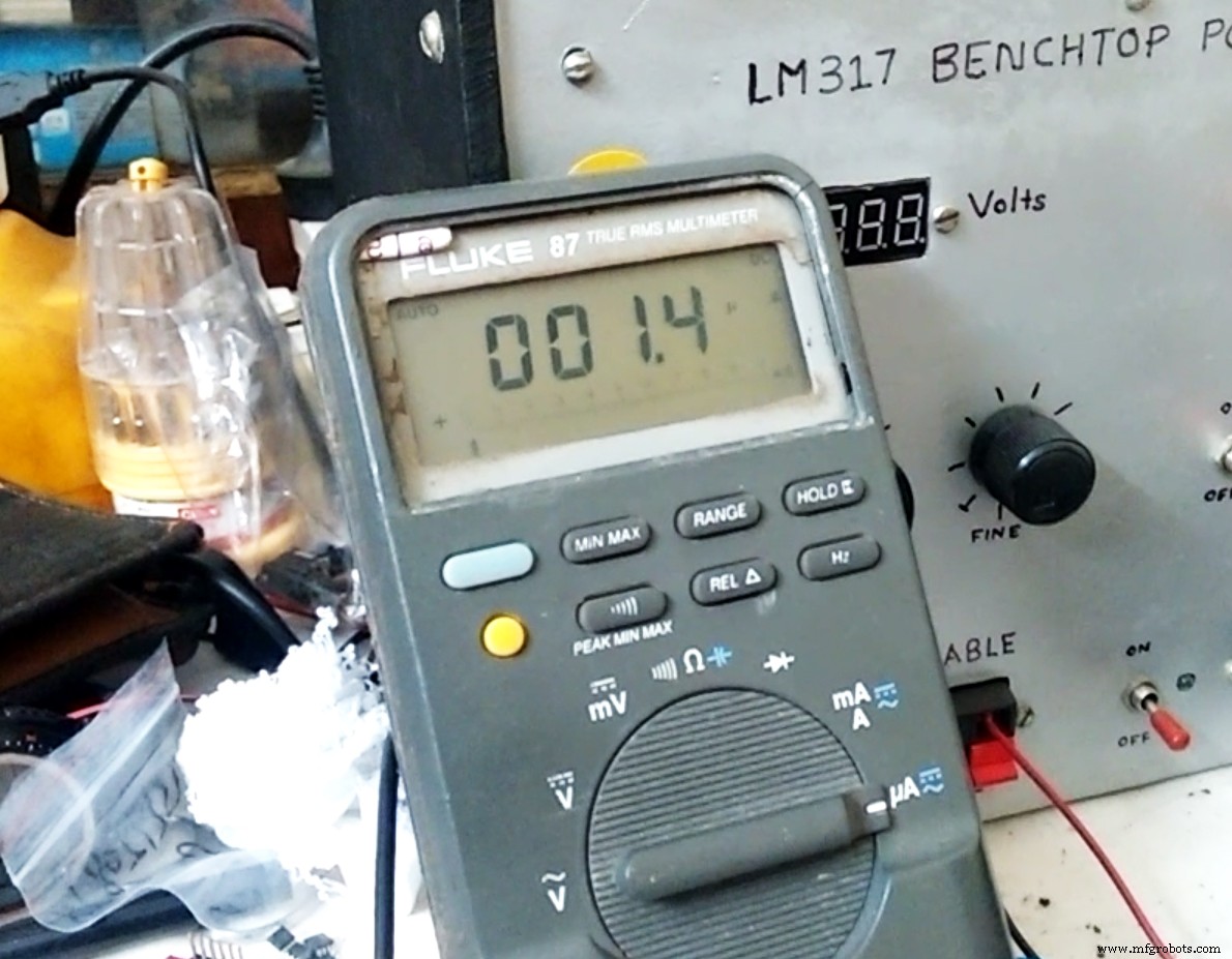
Here's the actual reading of the current consumed by sleeping ATmega168P @1MHz.
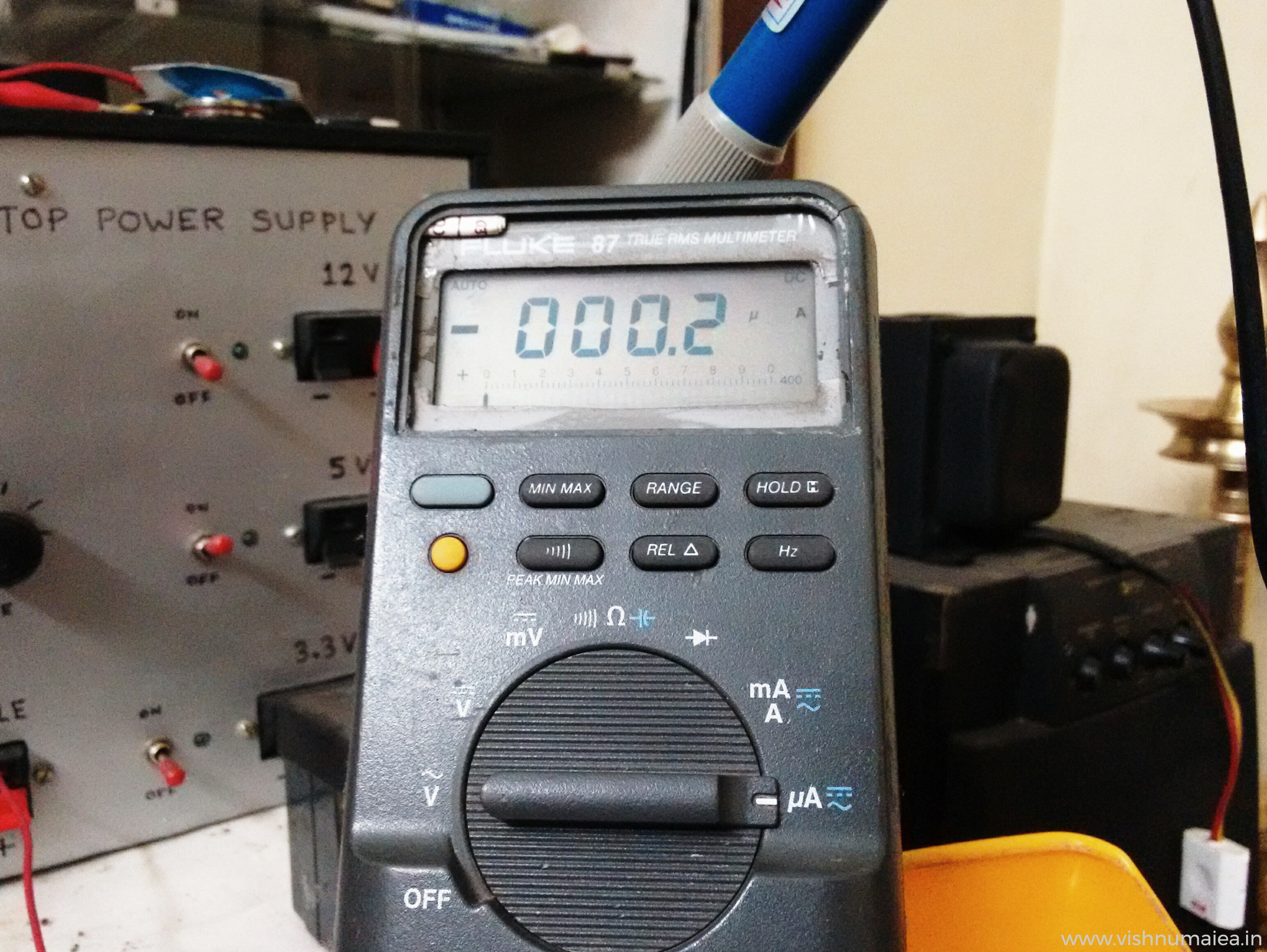
The value hops between 0.1 uA and 0.2 uA due to the lack of precision. But such a precise measurement isn't necessary but would've been interesting to see.
The power consumption of ISL1208 RTC at max is 1.2 uA . So if we add this with the power down mode current consumption of the MCU we get 1.2 + 0.2 =1.4 uA . My meter measured between 1.4 uA and 1.6 uA which justifies the calculations. The variations is only due to the lack of precision and our approximation or rounding of numbers.
Here's an unlisted video from my YouTube channel where I show the testing.
Now let's do the simple math to find how long we can the system on a coin cell. The CR2450N from Reneta has a nominal capacity of 540mAh . I have two red SMD LEDs on the system which consume about 6 mA (even with two LEDs) with when turned ON. So that's the peak current consumption of the device at worst. How long these LEDs light up can be summarized as,
1. As long as the time setting switch is activated while you're setting the time (but you don't have to do this every year)
2. The 6 second delay before sleep.
3. LED flashes on your birthday and stay ON for about 19 seconds.
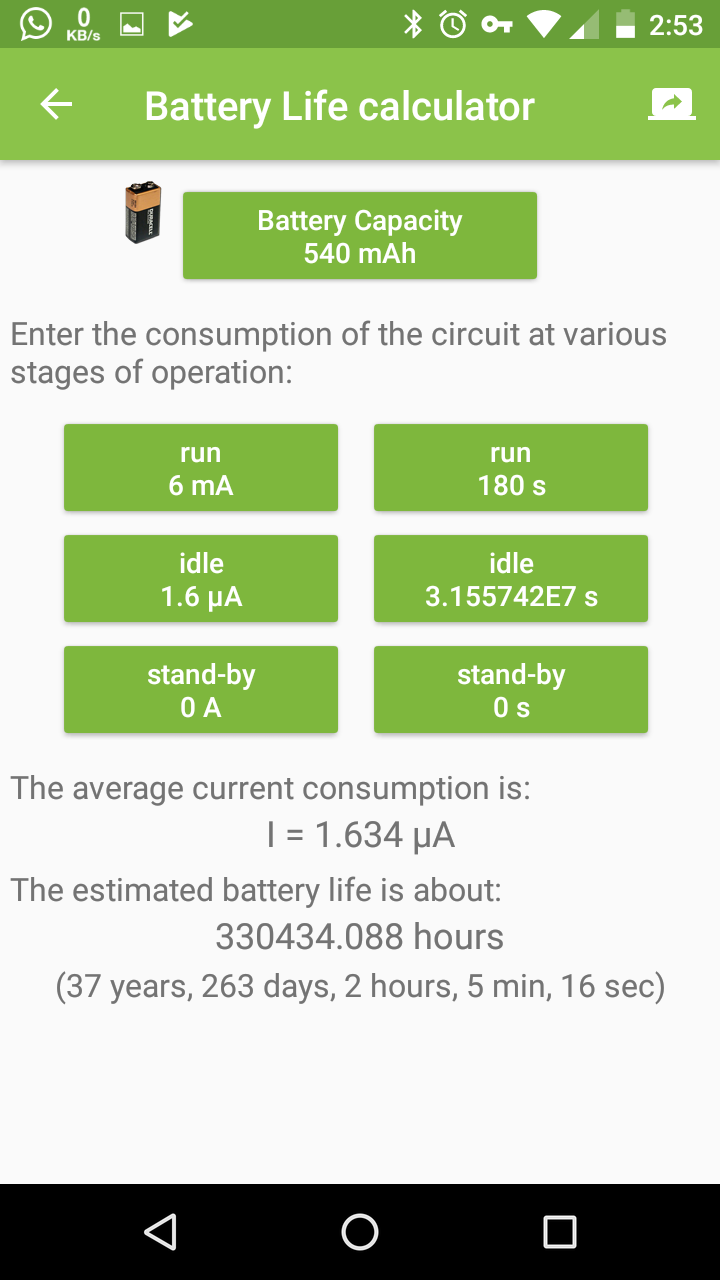
Let's not be accurate here but just make an approximation. Let's assume the time setting requires 2 minutes (LEDs will be ON for 2 mins) and and additional 1 minute ON time for other things including the birthday flashing. So it's total 3 minutes or 180 seconds for which the system consumes 3 mA current. Let's take the sleep or idle current as 1.6 uA , though it's lower actually. There's 31557600 seconds in a year of 365.25 days. If LEDs stay ON for 180 seconds in a year and OFF for (31557600 - 180) seconds, then the average current consumption will be,
Average Current =[((6 x 10^-3) x 180) + ((1.6 x 10^-6) x 31557420))] / 31557600 =(1.08 + 50.491872) / 31557600 =51.571872 / 31557600 =1.634 x 10^-6 =1.634 uAh If the average current consumption is 1.634 uAh, then the 540 mAh cell can run the device for:
Time Span (approx) =(540 x 10^-3) / (1.634 x 10^-6) =330477.3562 hours =13769.88 days =37.699 years Note than this approximation is do not consider self-discharge of the battery. It'll be taken into account later. You can also use the ElectroDroid app to calculate battery life. Here's a screenshot of the calculations we just did.
BUT WAIT...
Can we reduce the current consumption further ? YES WE CAN! I made further optimizations to my design to limit the average current consumption to 0.6 uA , yes I did that. Not let's see what optimizations I did,
1. To remove the extra red SMD LED to reduce the current when the system is active/running. Before it was 6 mA at max with two LEDs. So with one LED, it'll be reduced to half, ie 3 mA.
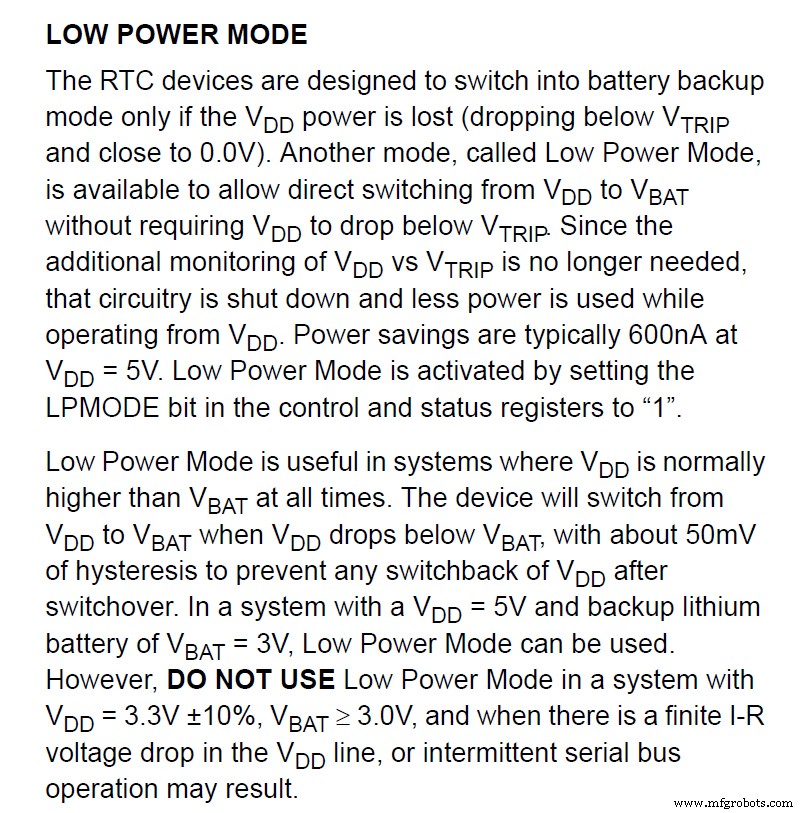
2. To reduce the current consumption of RTC, we need to disconnect the VDD pin of the ISL1208 RTC from the VBAT pin. Previously the VDD pin was connected to the VBAT pin where I supplied the 3V from the cell (you can see this in the schematic). In that configuration, I also had the LOW_POWER mode bit (LPMOD ) of the RTC set to 1 activating the low power mode. So now you might think if the low power mode is set, then the chip might be consuming the lowest current. But that's not the case when we have the VDD tied to VBAT. Because low power mode bit is only useful if we have VDD> VBAT all the time. At such situation, the RTC's internal power switch will select VBAT as power source reducing the current further by 600 nA when VDD>=VBAT (from typical 1.2 uA which I've mentioned before). But if we can run the RTC in VBAT only with VDD =0, the current consumption can be reduced to the minimum ie, 400 nA as per the datasheet. So what I did is, first I disabled the low power mode by setting LPMOD to 0. Then added a jumper to the RTC breakout board to disconnect the VDD pin from VBAT when I don't need it. Why need the jumper is because, the VDD pin must be greater than or equal to VBAT in order for the I2C to work. So I can connect the jumpers when I need I2C while I'm setting the time, and can disconnect it after. This will let the RTC to consume the targeted 400 nA current. Tada! We did it!
Now that we have reduced the current consumption of the RTC from 1.2 uA to 0.4 uA (400 nA), we can do the math again!
System Active Current =3 mAh max
System Sleep Mode Current =0.4 uA (RTC) + 0.2 uA (MCU) =0.6 uAh
System ON time =60 s (time setting) + 19 s (birthday flashing) + 6 s (before sleep) =85 seconds
System Sleeping Time =31557600 s - 85 s =31557515 seconds
Total time in a year =31557600 seconds
Battery capacity =540 mAh

Here's the current consumption test video after the optimizations and mods.
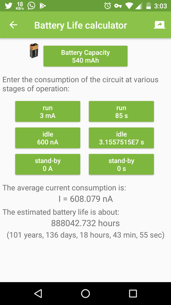
If we put those new values to the ElectroDroid's battery life calculator, we get, 101 years and 136 days. A theoretical operating time of more than a century! The average current consumption is now only 608 nA . Here's the screenshot.
Okay, What's the actual operating time ?
Batteries aren't perfect, nor anything we design. So let's also consider the 1% self discharge of the cell into account.
1% of initial capacity of 540 mAh CR2450N =5.4 mAh
Self-discharge current =5.4 mA per year or 616.4 nAh (5.4 mA / hours in a year)
Adding this 616.4 nAh with the 600 nAh sleep current =1.216 uAh
Expected operating time with average current of 1.224 uAh =50 years, and 131 days.
That's the actual operating time if the cell will be fine
Here's a table of actual operating times of different types of coin cells with the 1% self-discharge of initial capacity every year.
The main practical concerns associated with running the device for such long periods are,
1. Will the battery retain the charge and voltage for that long ?
2. The effects of environmental variations on the circuit and battery performance.
3. And you screwing up things! XD (don't drop it, chew it, sit on it, run your car through it or launch it into space!)
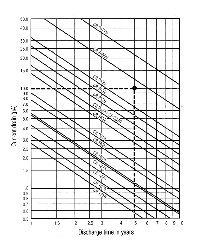
Coin cells are usually made to last for 10 years, which is their shelf life , and some even last longer than that. But that doesn't mean they'll start to disintegrate to an useless state after that. If the cell is physically fine, it can still power things. As per Renata datasheet, the self-discharge rate of CR2450N is less than 1% of the capacity every year. As per this datasheet from Energizer, that 1% figure is of the fresh capacity. Below is a chart that shows the standard discharge time in years (this doesn't consider the self-discharge or other exceptions). It clearly shows the theoretical expected operating time is way too longer than 10 years.
Self-discharging not only reduces the capacity but also reduces the voltage. Both ATmega168P and ISL1208 are designed to be operated fine at voltages as low as 1.8V. So the reduction in voltage might not be a problem. You can learn more about running systems with coin cells here.
To ensure long operating span, we must make sure the device is properly concealed against much of the environmental changes such as temperature, humidity, corrosion etc. These are some things you can do to protect your circuits,
1. Coat the PCB with long lasting conformal coating.
2. Place a pack of silica gel inside the enclosure.
3. Seal the enclosure with less temperature conductive materials and make it air tight.
4. Place it somewhere safe from naughty hands!
Step 10:Building
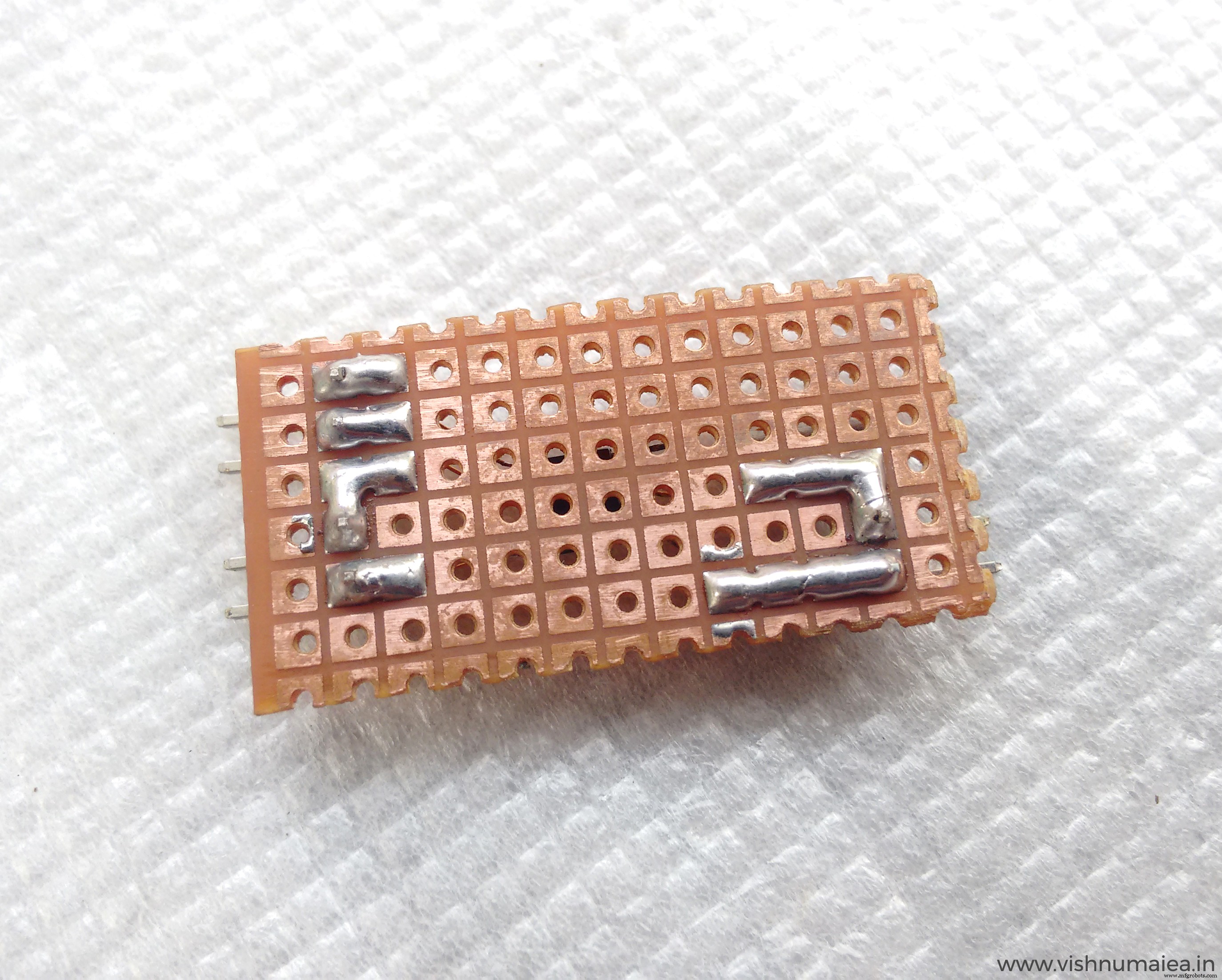
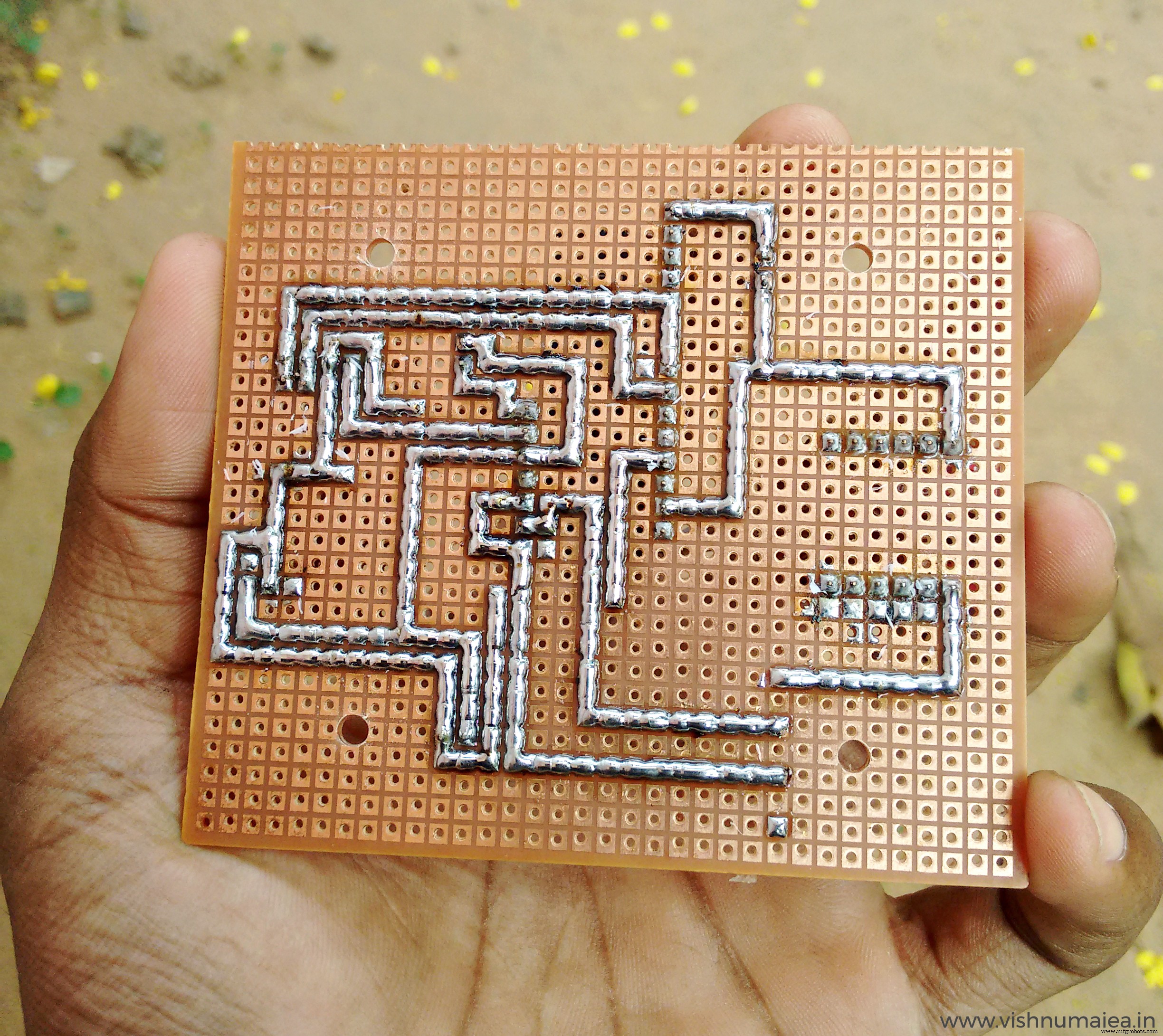
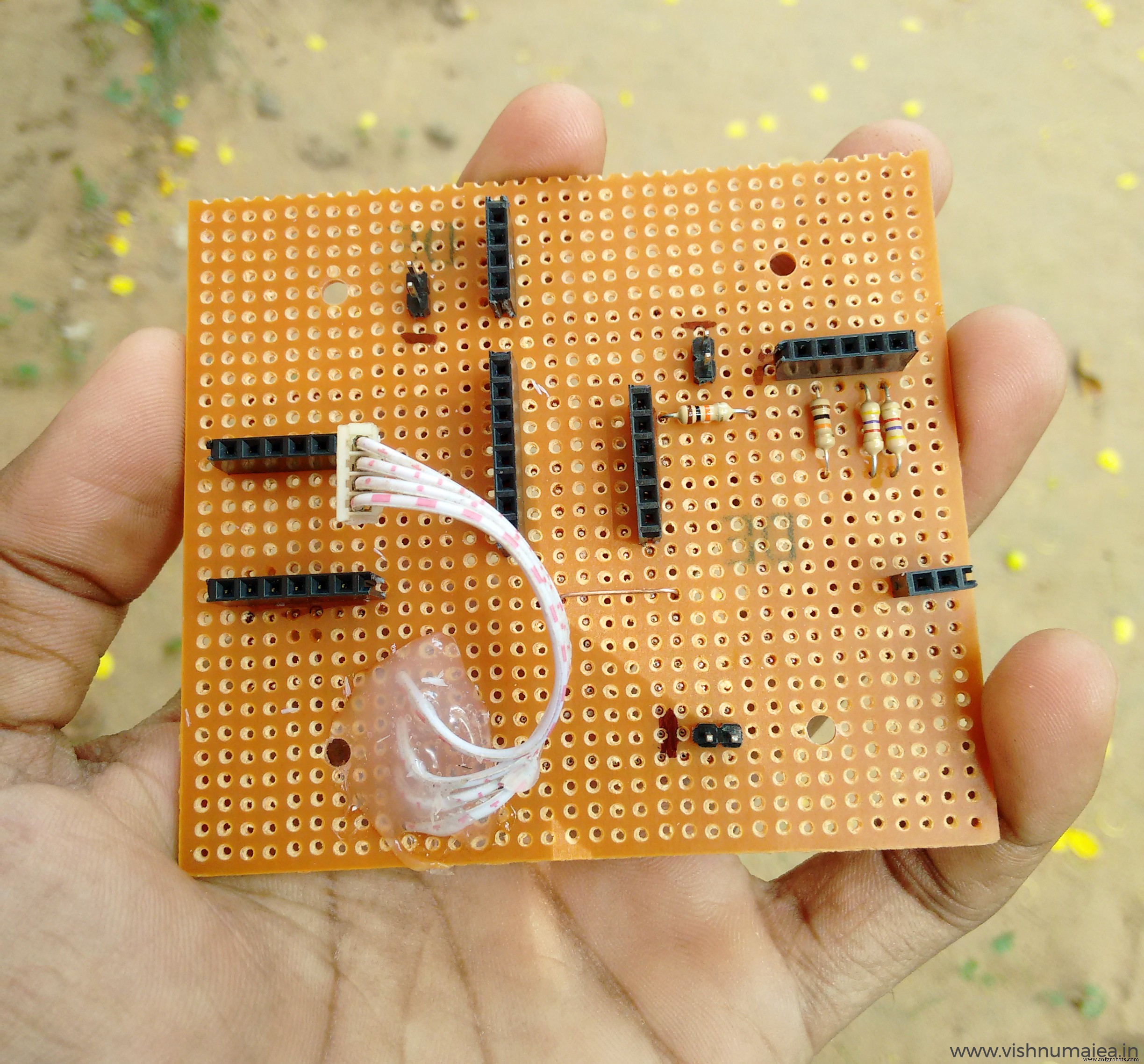
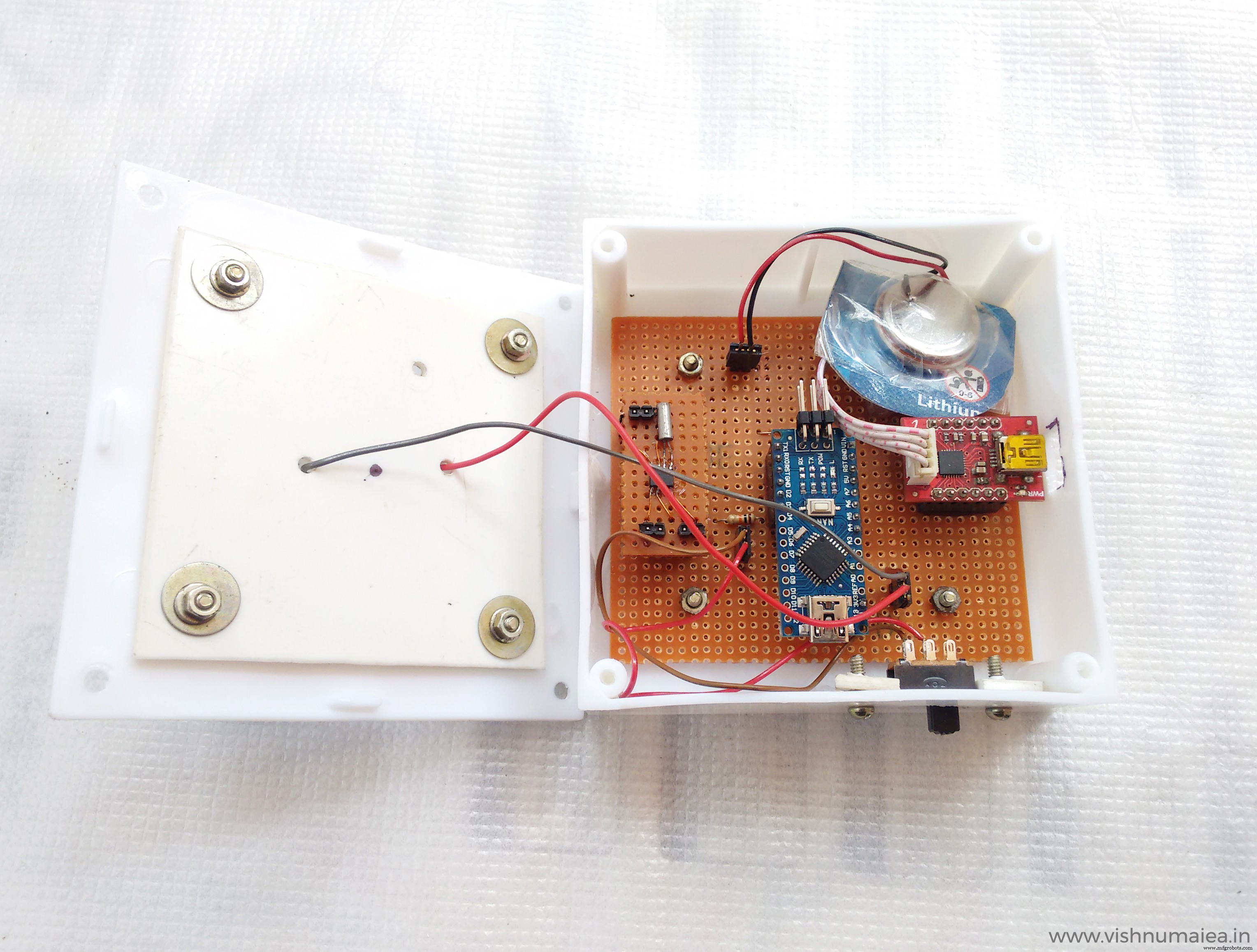
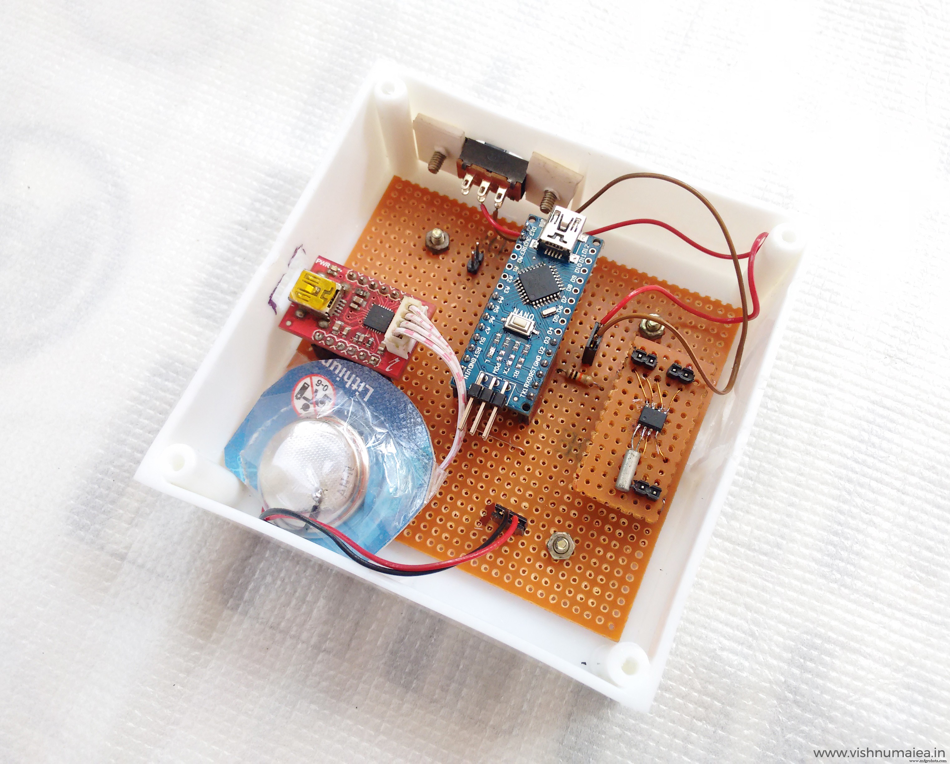
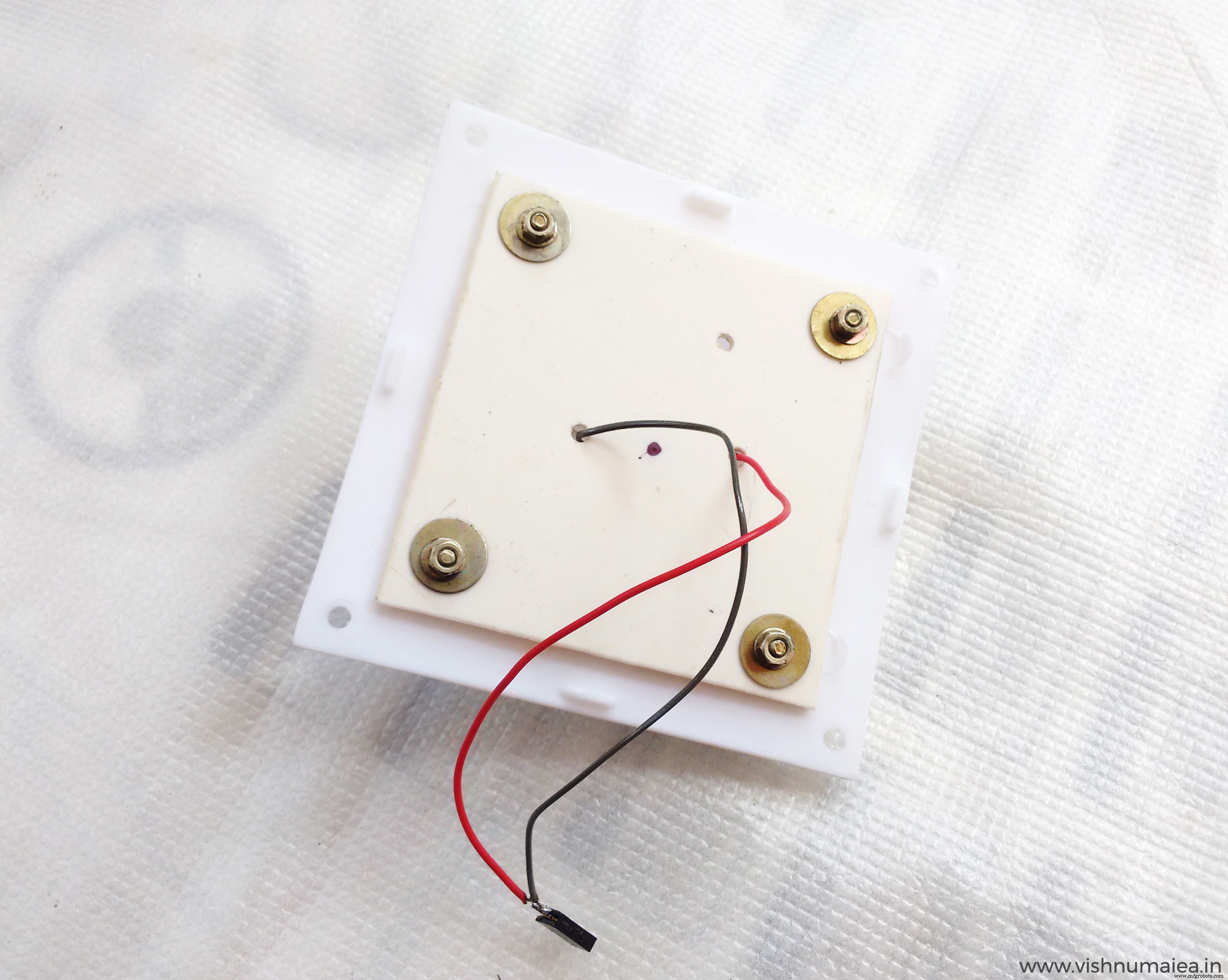
I used a perfboard to solder everything as per the schematic. I used berg connectors for the battery, switch and LED so that it'll be easy to remove them if needed. Below are the some images of the PCB.
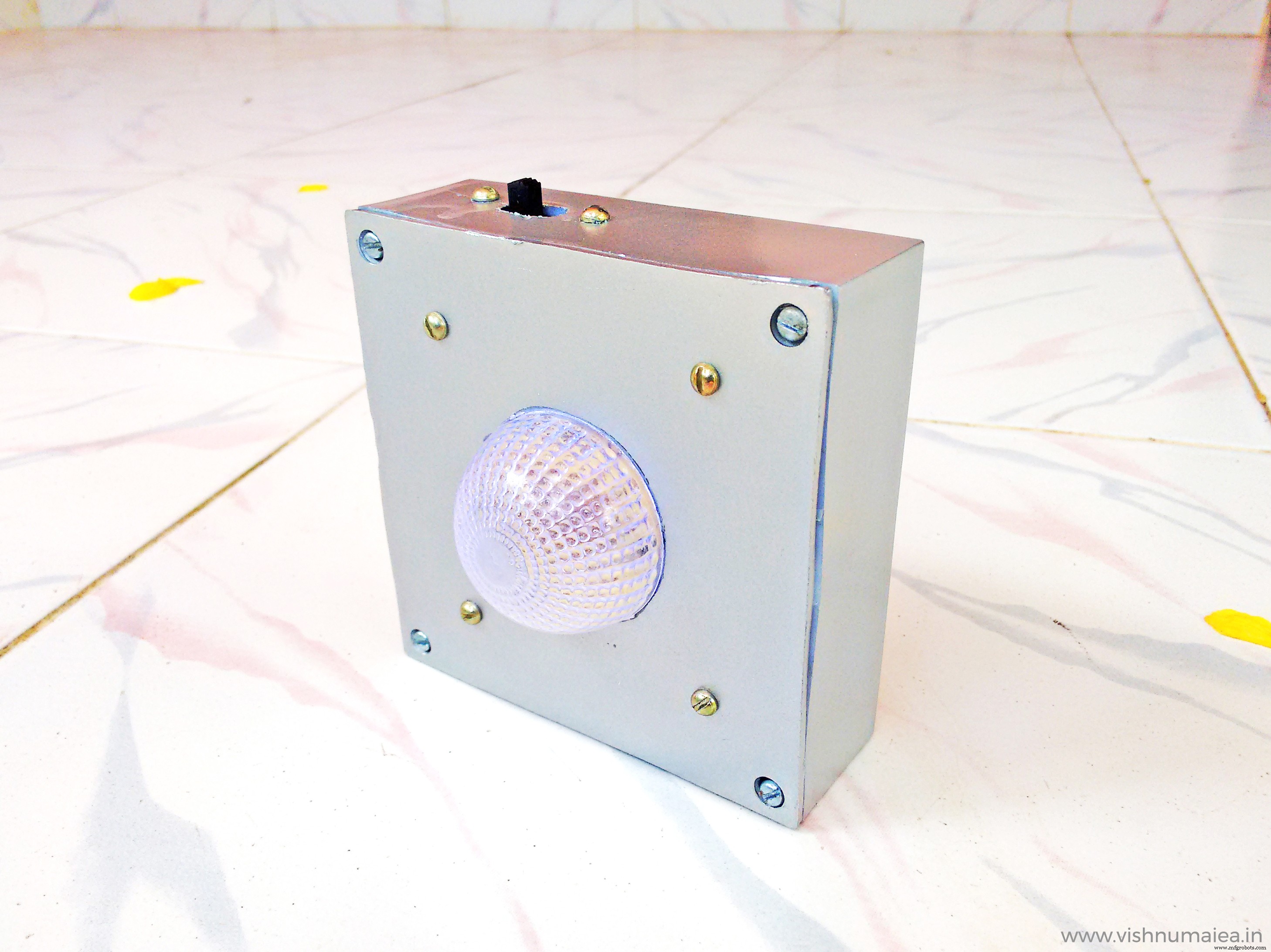
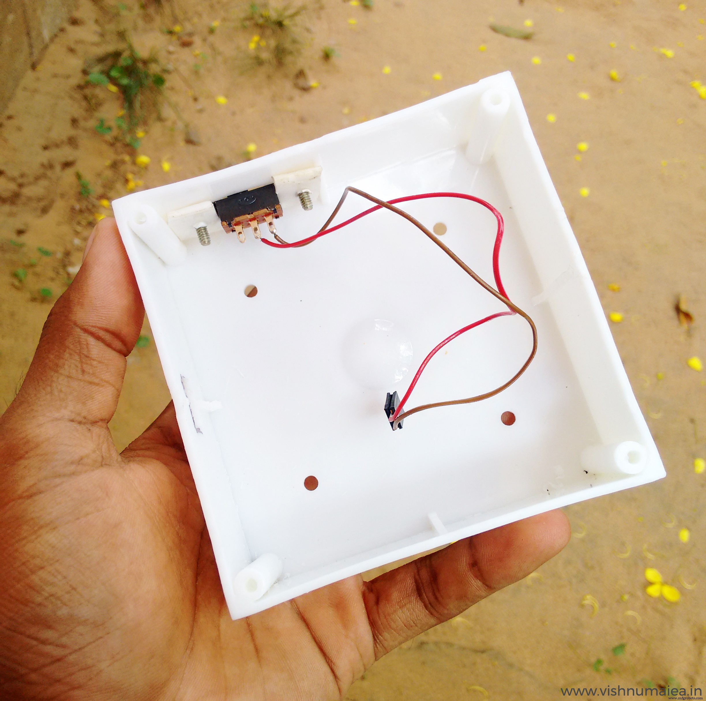
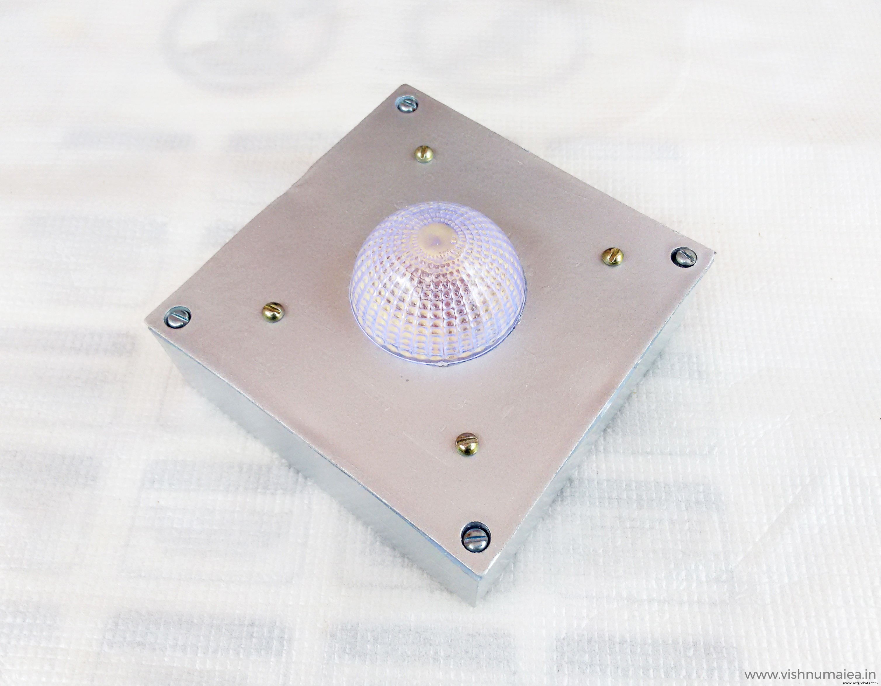
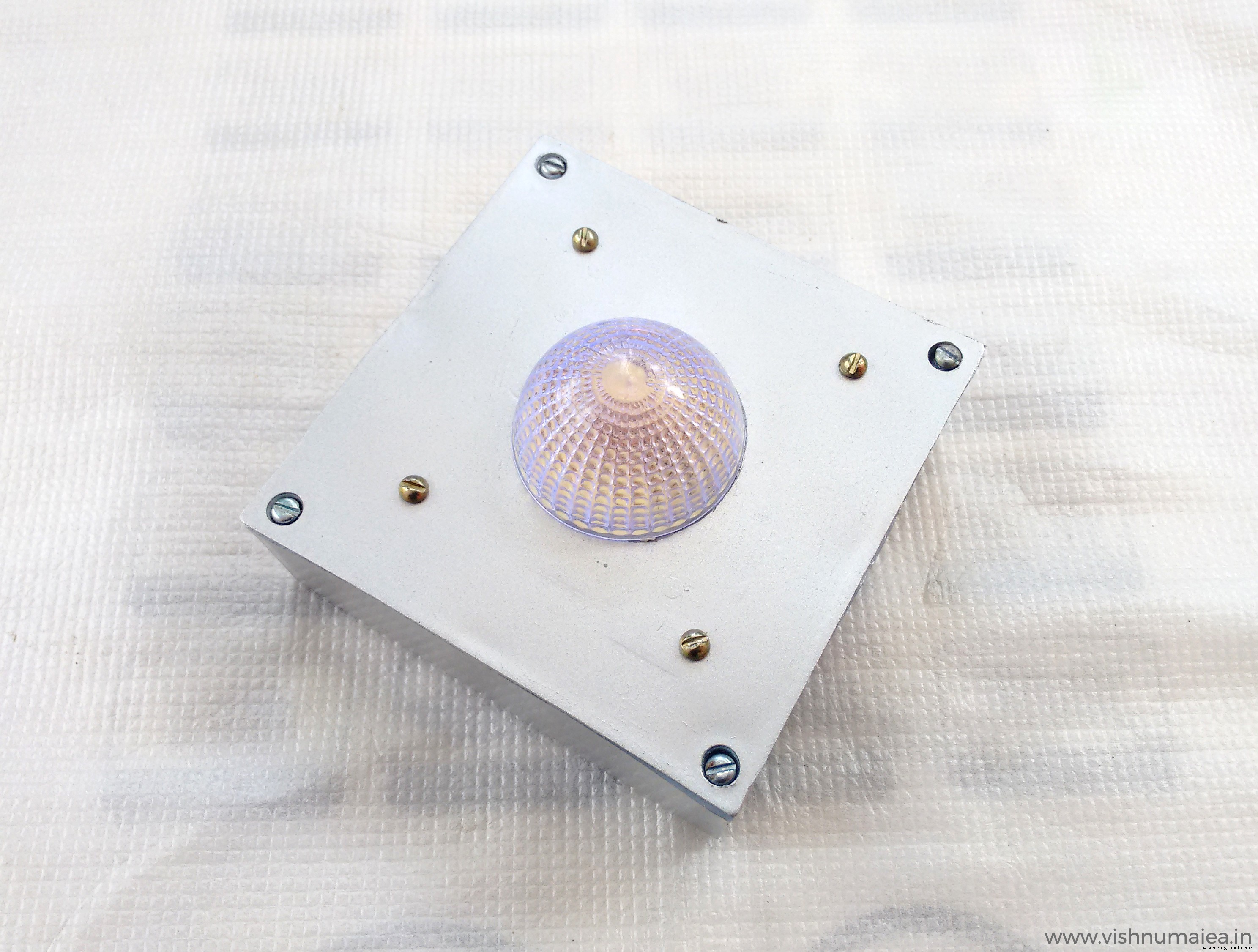
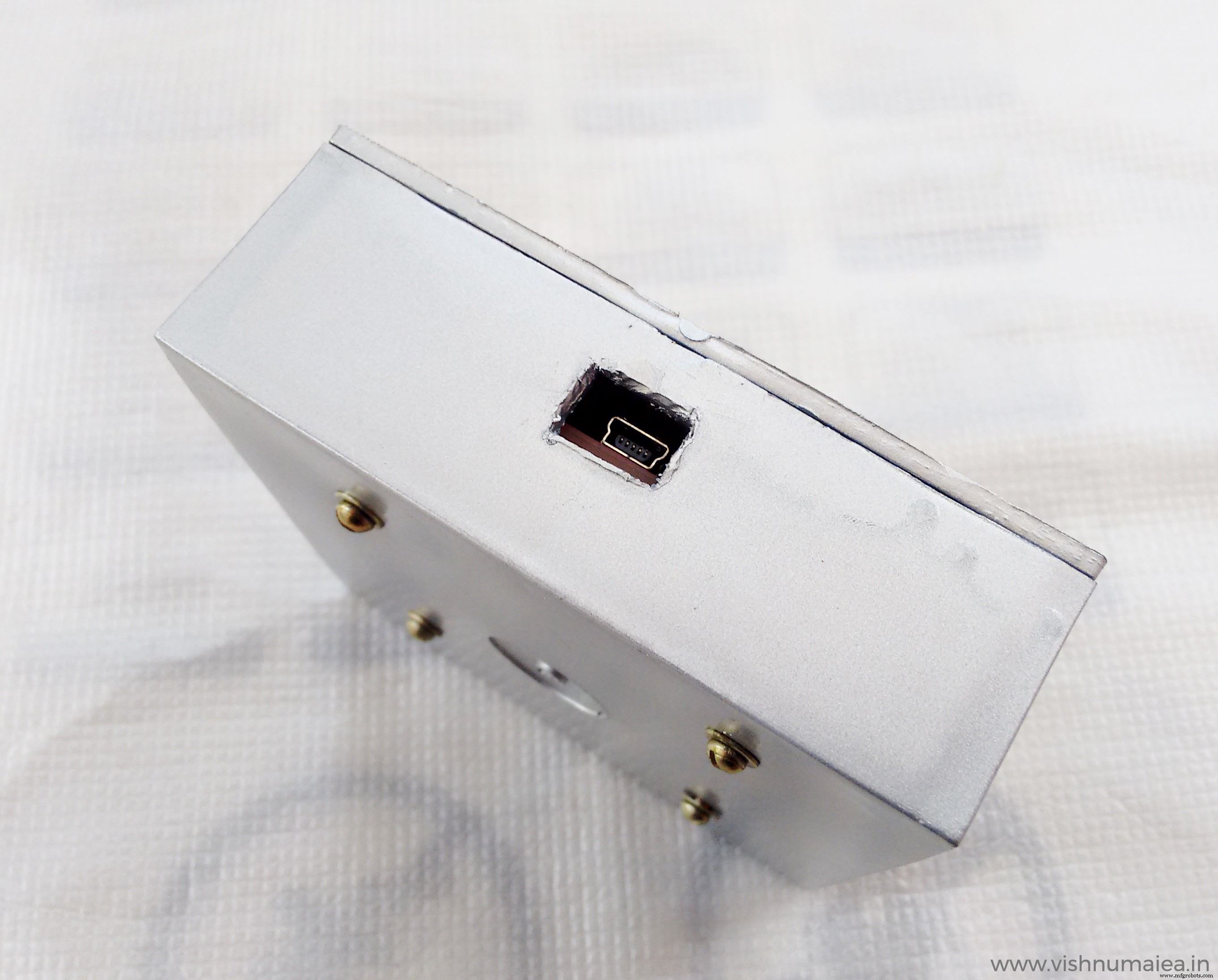
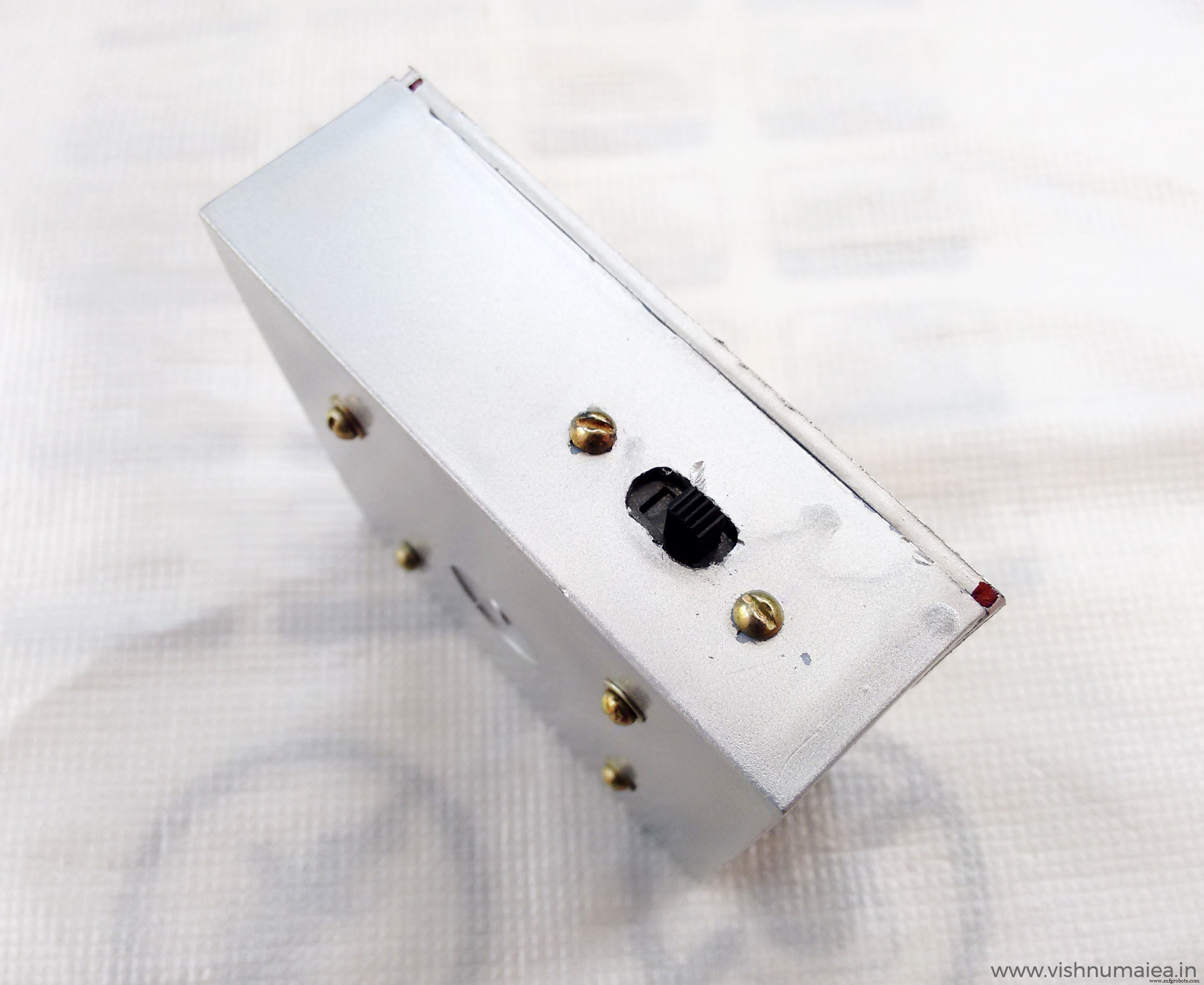
To build the enclosure I used a 4" x 4" switch box which I bought from an electrical shop. I made two rectangular holes for the switch and USB. You can 3D print an enclosure if you want; sadly I don't have one. The dome was snatched from a cheap LED light and used super glue to fix it on the box. I painted it with silver spray paint.
Use your ingenuity to build it.
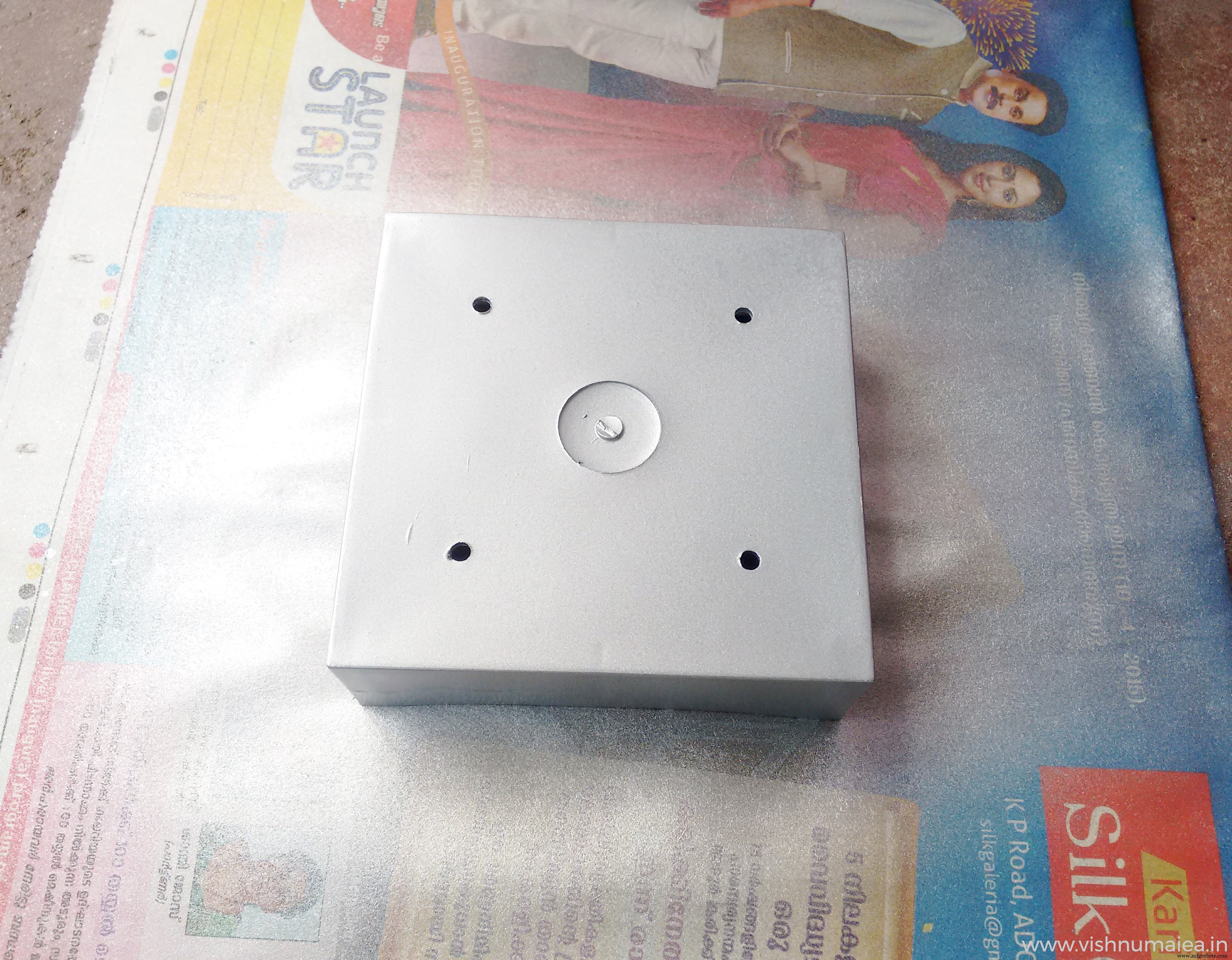
What missing is some decorations . I'm not good at decorating things. If you are going to gift this to someone, you know what to do.
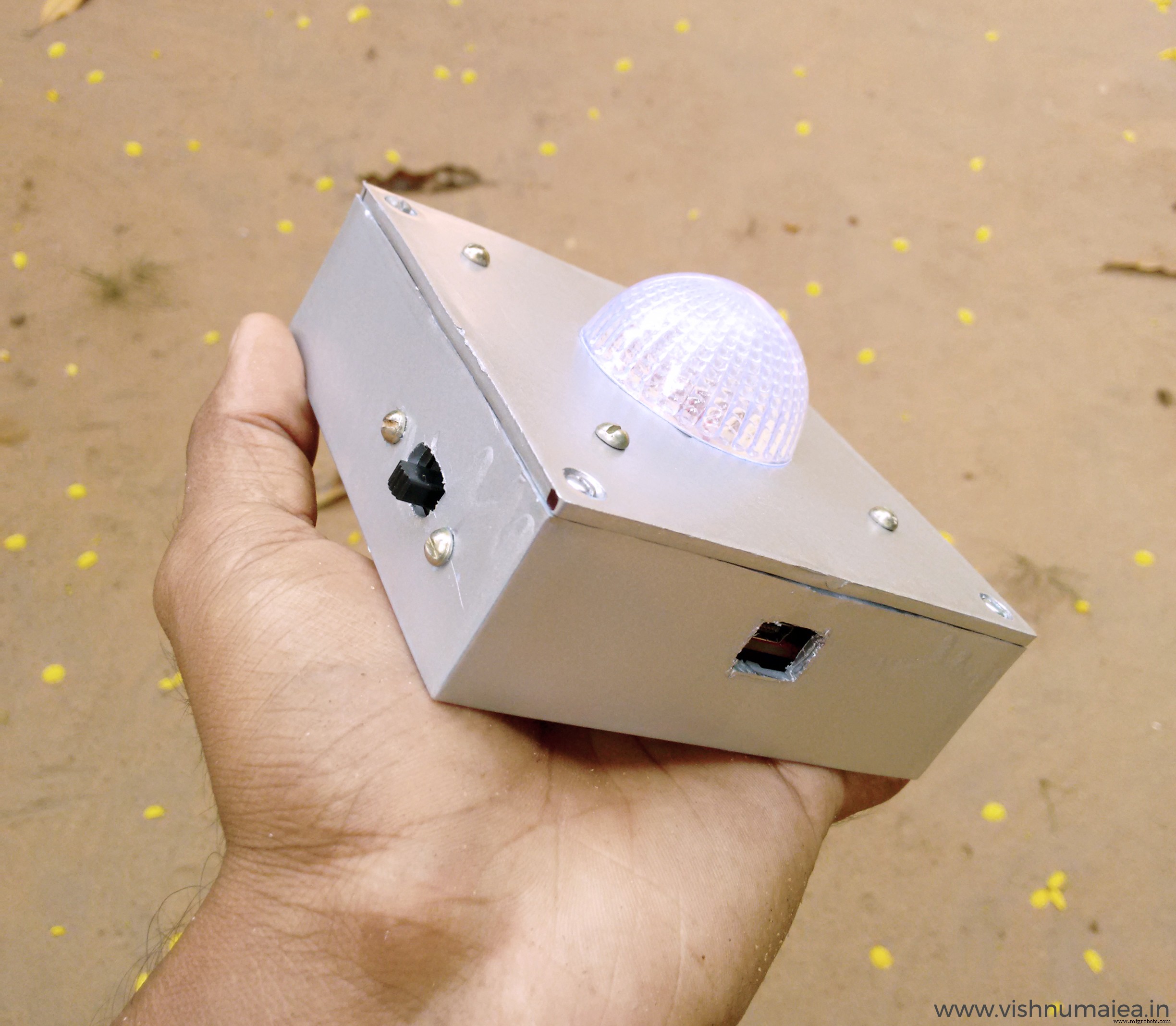
The final output is satisfying to the extend of my hardwork. I might find someone else to decorate it.
Step 11 :Improvements
总有改进的余地。 Some of my suggestions are,
1. Using a Nokia 5110 LCD with or instead of the LED bulb. The LCD controller only consumes a couple of 100 uA at normal operating modes without the LED backlighting of course. Monochrome LCDs only consume extremely low currents. So using it would be better than a flashing LED, where you can actually print the happy birthday message on the screen itself. I might do this in future because I have couple of them lying around here.
2. A software that runs on the computer that'll set/sync the time accurately and automatically. I'm thinking of developing a simple one using Processing.
3. Flashing the LEDs to indicate the current age - for example if it's your 5th birthday (OMG are you're reading this ?!), it'll flash a sequence for 5 times. Currently you can not set the current age in the system. You may add this.
4. Designing a dedicated PCB in eagle (planned).
5. If blinking LED isn't your thing you can actually make this more exciting with for example using an opto-coupler you can turn on an AC alarm, music player, lights or anything you want to blink, move and scream on the birthday of the one you wish. You can even exclude the microcontroller and only use the interrupt from the RTC. Everything's possible!
So what are you waiting for ? Make one, decorate it with stickers, color papers, glitter or anything and gift to your loved ones or even yourself! And tell them to wait for this magical device to wish them happy birthday.
What you see here is actually a prototype of a device that'll refine and release in future. So stay tuned. Please feel free to share if you have found any errors with this documentation or have any improvement suggestions. Happy making :)
代码
Birthday Alarm
https://github.com/vishnumaiea/Birthday-Alarm示意图
Schematic of Arduino clone.制造工艺