

Arduino DCF77 分析器时钟 MK2
组件和用品
 |
| × | 1 |
关于这个项目
这个时钟看我的网站 Arduino DCF77 Analyzer Clock Sitehttp://www.brettoliver.org.uk/DCF77_Analyzer_Clock_Mk2/Arduino_DCF77_Analyzer_MK2.htm
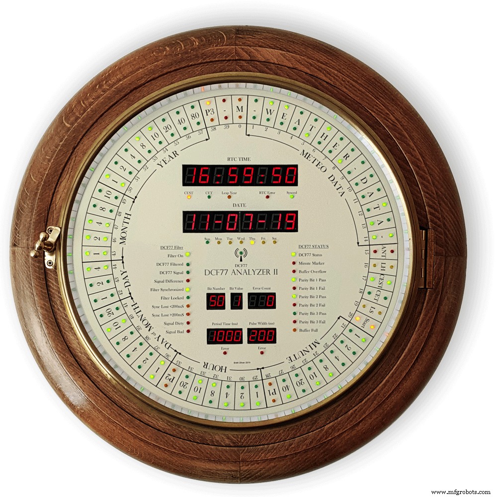
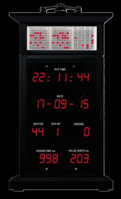
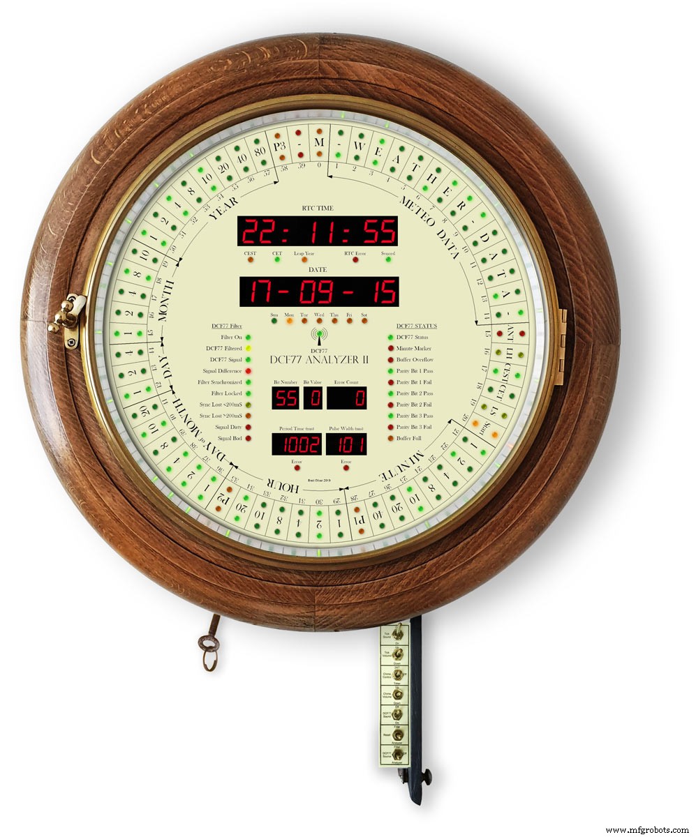
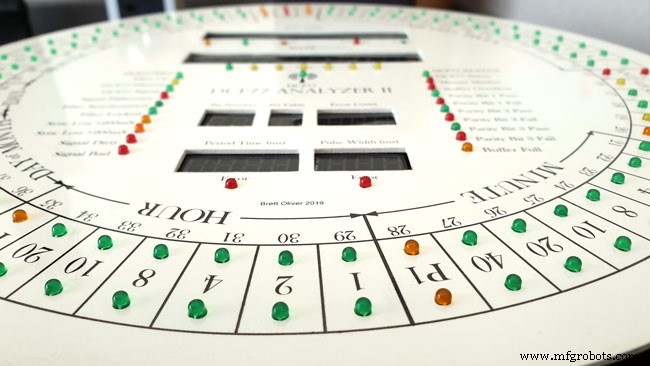
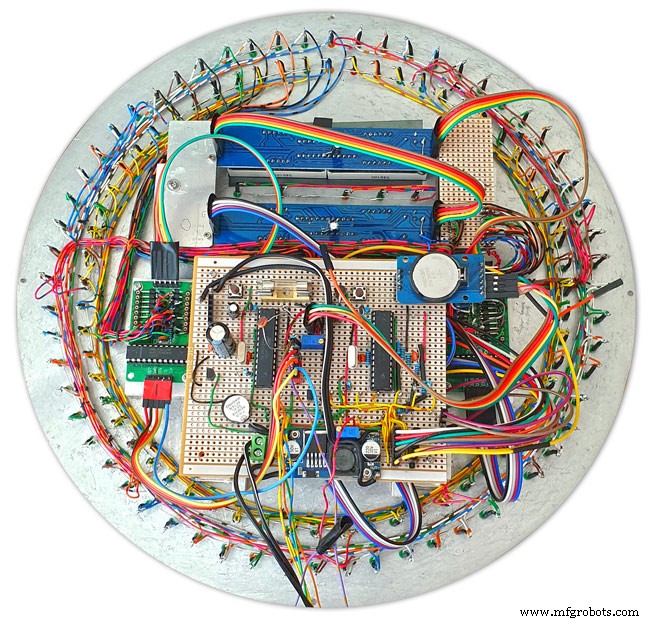
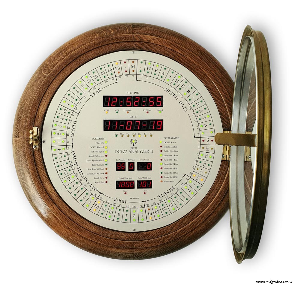
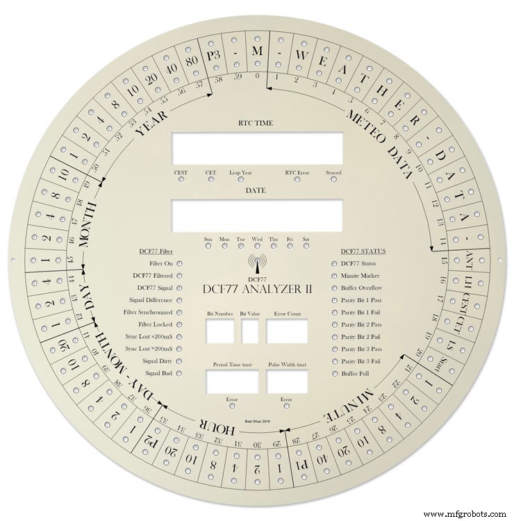
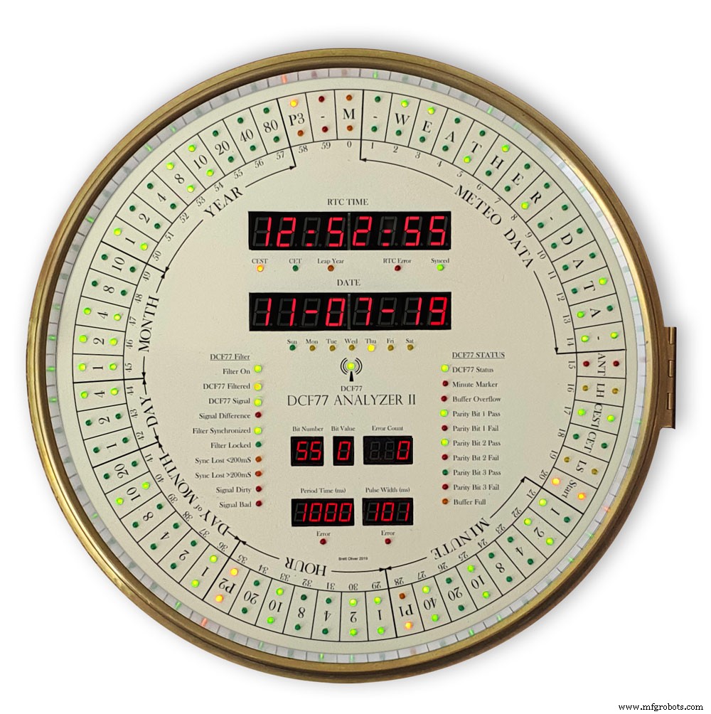
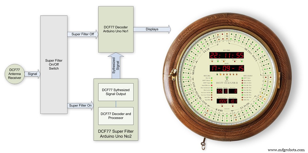
此时钟在直径为 12 英寸(305 毫米)的大表盘上的 2 个 60 个 LED 环上显示 DCF77 时间码。内环显示接收到的下一分钟的实时时间码,外环显示当前时间因为前一分钟的接收没有错误。
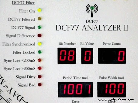
另外 24 个 LED 显示解码器状态和时间信息。解码的时间和日期显示在 2 个大型 8 位 7 段显示器上,而 DCF77 脉冲时序和位信息显示在另外 2 个较小的 8 位 7 段显示器上。
时钟使用 2 个 Atmega 328 微处理器 (Arduino Uno),1 个控制 DCF77 分析仪,1 个控制 Udo Klein 超级滤波器。超级滤波器允许先进的 DCF77 信号处理和 Arduino 石英晶体的调谐。滤波器是可切换的,有 10 个状态 LED,用于显示信号接收状态和输出质量。时钟还通过 2 个关闭的 JQ6500 声音模块报时、刻钟和秒。
大多数电子设备都安装在表盘的背面,因此时钟可以安装到许多不同的表壳样式中。
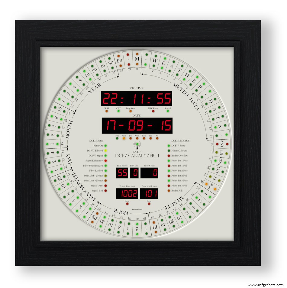
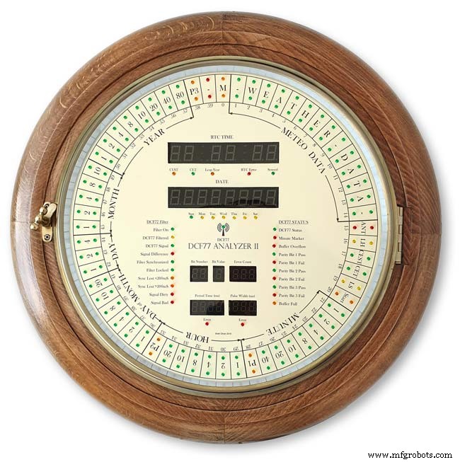
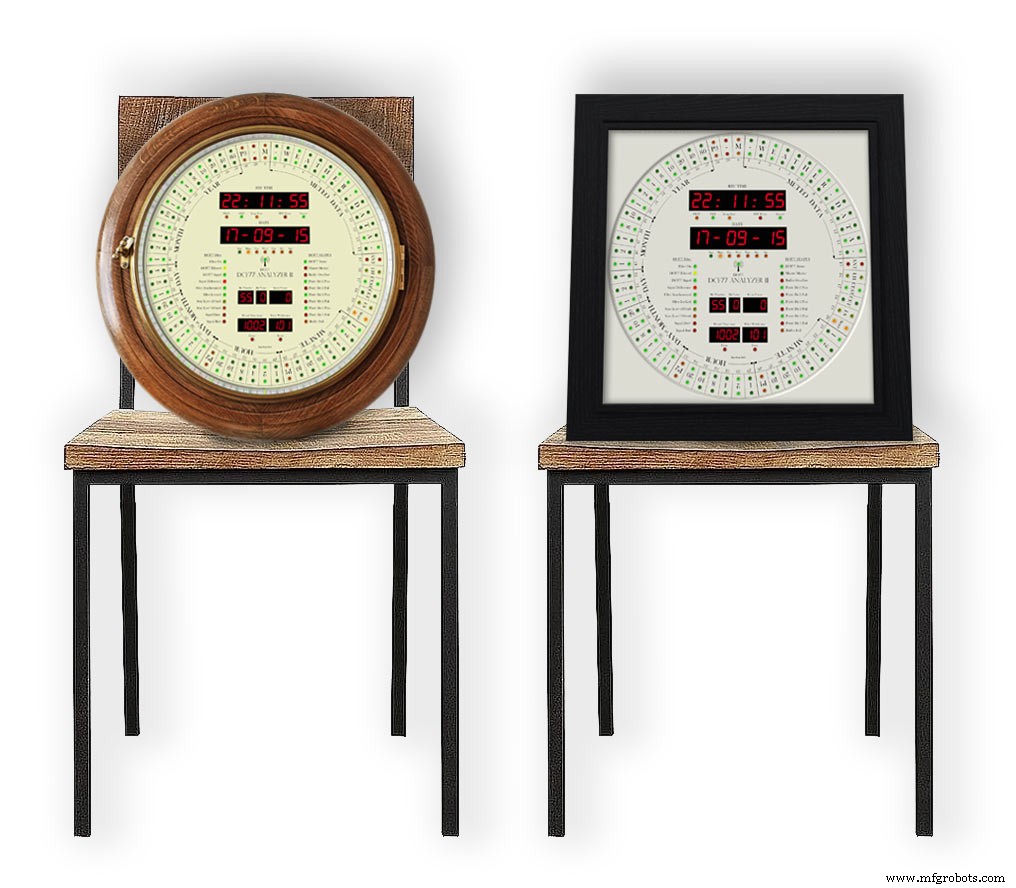
我已经包括了复古和现代风格的钟壳设计。复古的设计被装进了一个旧的表盘钟壳,而现代的设计被装进了一个黑色的相框。
第 1 步:信用
该时钟基于 Erik de Ruiter 的 DCF77 Analyzer Clock,是我的 Mk1 DCF77 Analyzer 时钟的更新版本。
高于 Erik de Ruiter 的 DCF77 分析仪时钟,低于我的 MK1 DCF77 分析仪时钟。
Erik 在 GitHub 上提供了他的时钟的完整细节
Eric 的时钟和我的时钟之间的差异
虽然基于 Eric 的时钟,但我对硬件做了一些更改。请混合搭配适合您需要的任何选项,但请确保更改代码以适应。
我在 Veroboard 上使用了两个定制的 Arduino UNo,而不是一个 Uno 和一个 Mega。
我一直使用来自中国的廉价 7 段显示器和点阵模块,并更改了代码以匹配。请参阅有关显示错误的部分,因为一旦执行了这些 mod,它们就可以很好地工作。
我使用 2x JQ6500 模块而不是 Adafruit 音板。因为我的一块板是软件控制的,所以有一些软件更改和另一个要加载的库。
由于我有一个 Arduino Uno 而不是 Arduino Mega,我没有所有备用引脚来驱动解码器 LED,所以我使用了第三个点阵模块。
我通过添加额外的状态 LED 修改了 Udo Klein 的超级过滤器。这些 LED 的亮度由 DCF77 解码器 Uno 通过 2 个晶体管而不是超级过滤器 Uno 进行 PWM 控制。
Super Filter还增加了LED测试功能,配合DCF77解码器测试功能。
我只使用 3 毫米 LED 并选择了匹配亮度的 LED 来尝试保持亮度均匀。
我在软件中添加了 4 个单独的强度级别,因此环形/状态 LED、大型 7 段显示器、小型 7 段显示器和超级过滤器 LED 都具有自定义亮度级别,具体取决于单个 LDR 的读数。
我的时钟上没有温度或周数显示,并且修改了代码以适应。
我在我的超级过滤器中添加了额外的监视器 LED,所以在我的时钟上只有合成和非合成输出的选项。这不是根据 Erik 的时钟切换模式的选项。
我的时钟上的 DCF77 声音已经过修改,以突出传入 0 和 1 之间的差异。当时钟检测到 1 时,它只会播放比 200 毫秒稍长的声音。
第 2 步:视频
视频显示时钟在滴答声的情况下运行,并且时钟在整刻和整点报时。
它还显示表盘布局和阅读显示器的信息。
视频 2
显示开机、显示测试和时间/日期解码的视频
视频 3
显示 Udo Klein Super 过滤器如何在此时钟上工作的视频
视频 4
视频显示相框时钟在滴答声下运行,时钟在整刻和整点报时。
它还显示表盘布局和阅读显示器的信息。
视频 5
这个短视频展示了我的 DCF77 分析仪时钟显示和解码 DCF77 信号。所有声音都在 DCF77 现场信号之外。
第 3 步:控制
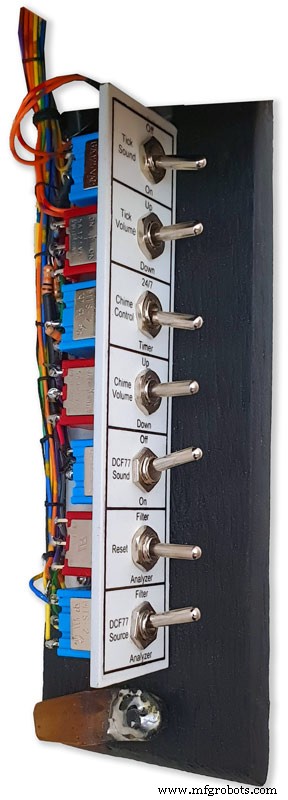
时钟由安装在金属条上的 7 个开关控制。开关连接到铰链门的内侧,该门可折叠在时钟下方以方便使用。
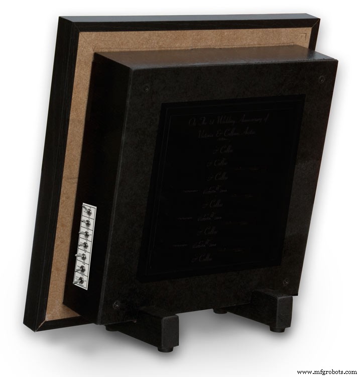
在相框版本上,开关安装在时钟侧面的切口上。
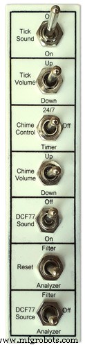
开关控制以下
滴答声开/关
滴答量
全天候 24/7 或定时器
铃声音量
DCF77声音开/关
重置超级过滤器或分析器
DCF77 源来自滤波器、关闭或分析器
切换功能
滴答声
打开和关闭滴答声(断开 JQ6500 模块的电源)
Tick Volume 非锁定
上下转动滴答声音量(滴答声开关必须打开)
铃声控制
关闭铃声已关闭
24/7 钟声 24/7
定时器铃声仅在一天中的设定时间响起,例如晚上休息
铃声音量非锁定
上调音量
Down 降低音量
每次按下按钮后都会播放测试铃声,以便您可以听到新的音量设置
DCF77 声音
On 播放通过压电发声器接收到的 DCF77 声音。
0 为 100 毫秒,1 播放为 500 毫秒的哔哔声,以便更容易区分接收到的 0 和 1。
关闭 DCF77 蜂鸣声关闭
重置非锁定
滤波器重置 DCF77 超级滤波器,使其重新同步到 DCF77 信号
如果启用,分析仪会从显示测试开始重置 DCF77 分析仪,然后进行时钟重新同步。 RTC时间将从实时时钟中存储的时间开始显示
DCF77 来源
Off 断开 DCF77 信号与时钟的连接
分析器 DCF77 信号直接馈入时钟,无需任何滤波
过滤 DCF77 信号取自超级滤波器,如果超级滤波器同步,则该信号被合成为正确的无错误信号
第 4 步:原理图
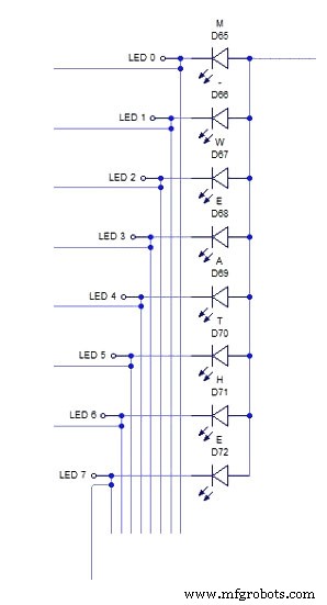
这个时钟有 3 个原理图。主板、点阵模块和7段显示模块。
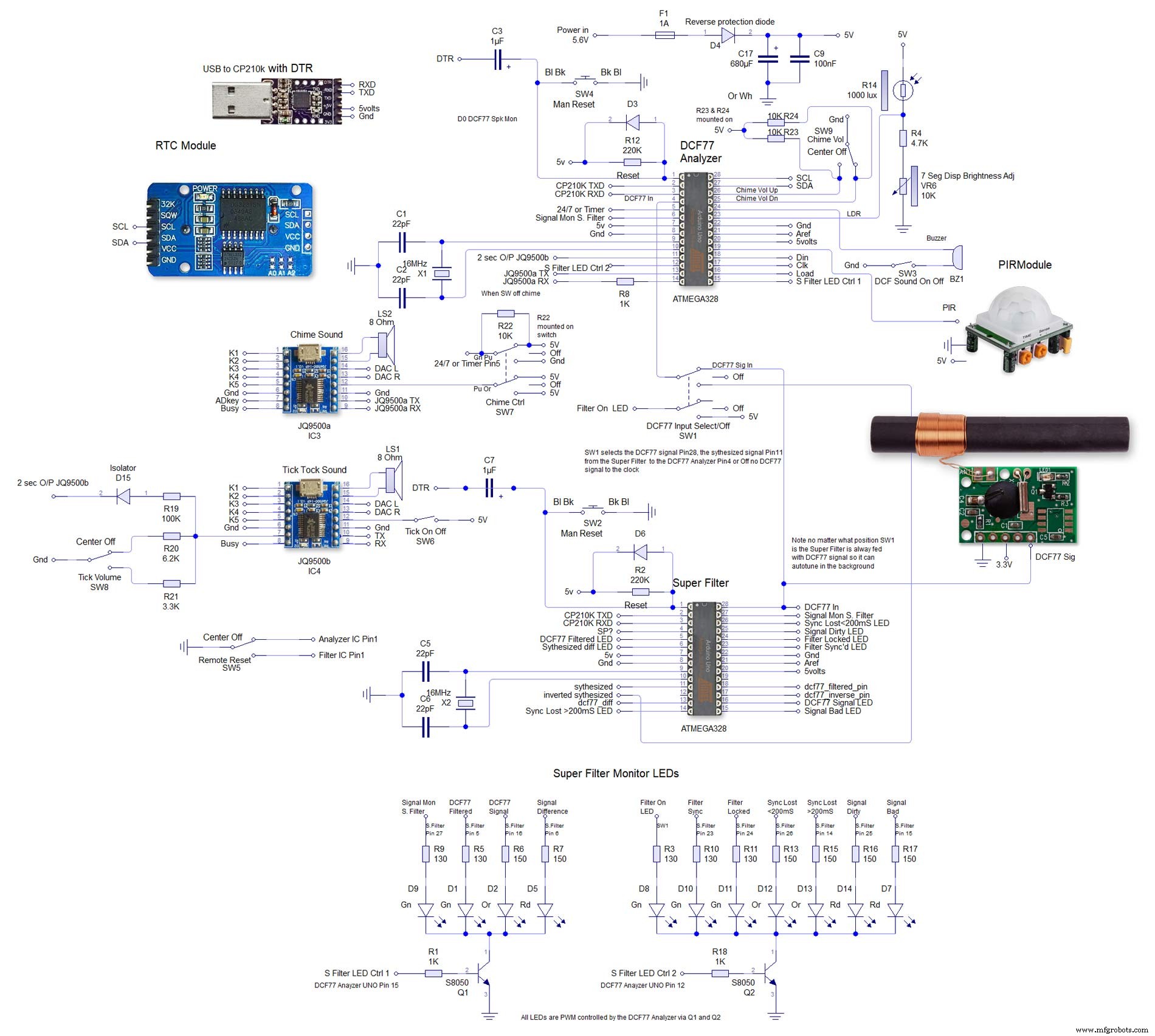
第二个是非常大的,可以在这里查看全尺寸 4000x4000 示意图。我这样布置是为了方便接线。

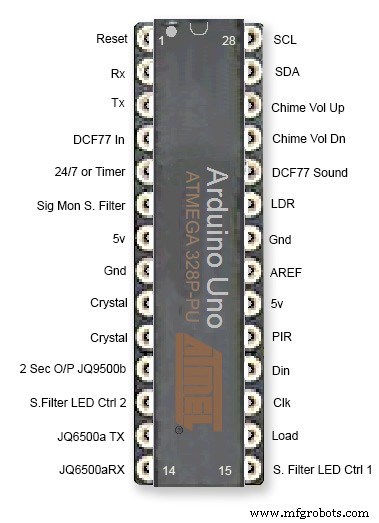
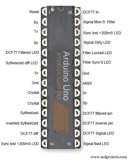
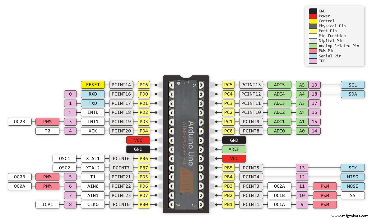
第 5 步:Atmega 引脚连接
该时钟在定制 vero 板上使用 2 个 Atmega 328 IC。标准 UNO 可用于时钟的分析器部分,但具有石英晶体而非谐振器的 UNO 必须用于时钟的超级滤波器部分。在此处查看如何将石英晶体添加到 Arduino UNO http://www.brettoliver.org.uk/Master_Clock_MK2/Master_Clock_MK2.htm#Mod
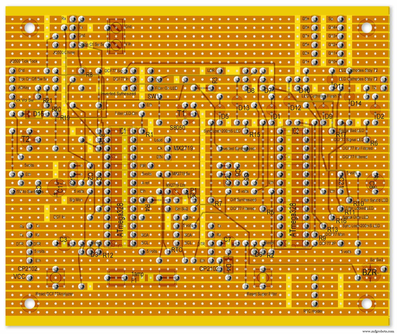
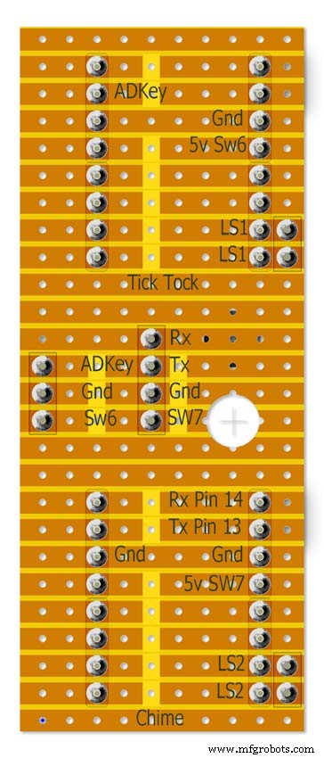
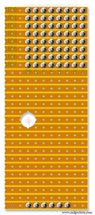
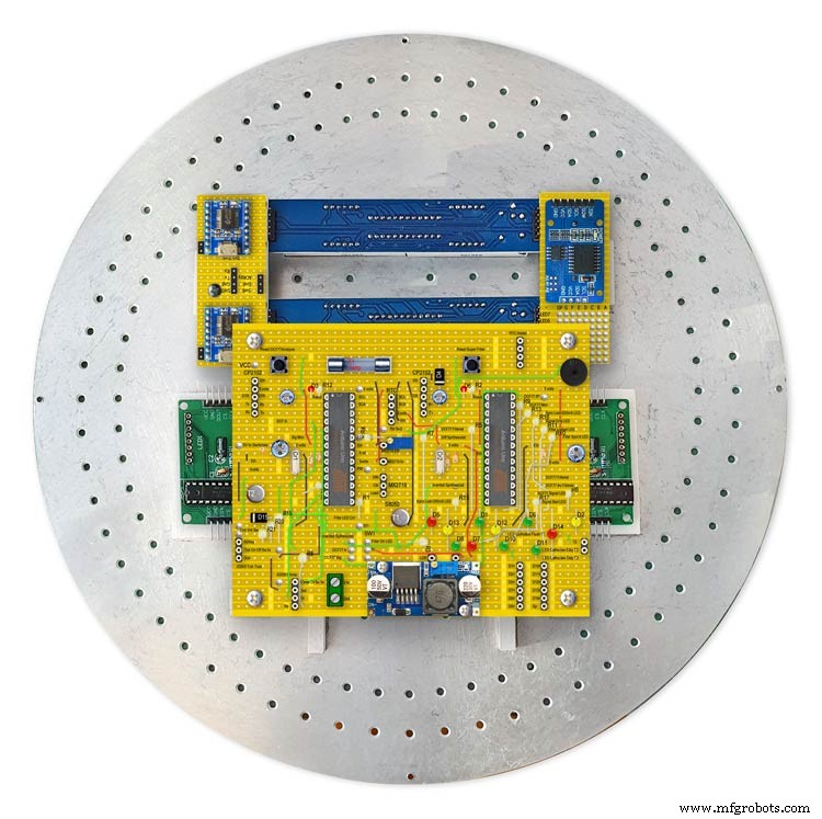
第 6 步:Vero 电路板布局
该项目的许多模块都是预先构建的,只需插入即可,但 Arduinos 的主板、声音模块和第三个 LED 矩阵需要在 Vero 板上构建。
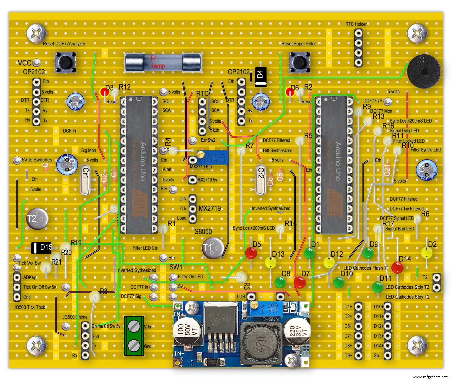
图中显示的 LED 安装在主板上,仅供参考。
从主板到其他板的所有接线都是通过 PCB 接头连接器进行的。从主板到开关面板的连接是直接接线的。这样就可以拆下主板和开关面板进行维护。
请注意,这些被配置为 Arduino UNO,虽然可以使用预制的 Unos 或 Nanoscould,但 Arduino 必须有一个石英晶体,而不是谐振器,以确保准确性,请参阅上面的 Atmega 引脚连接。
查看我的主时钟网站上的信息 Arduino 石英晶体修改

注意 RTC 安装在这里,但只能通过排线连接。
第 7 步:预构建模块
预制板和模块
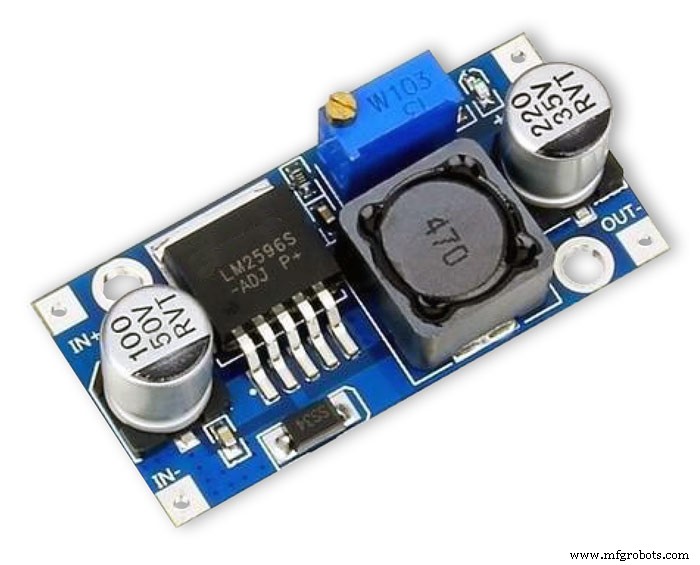
LM2596 稳压器模块将电压降至 5v。这是通过模块上的10K预置电阻来调节,在反向保护二极管D4之后测量。在将 Arduinos 添加到电路板之前进行调整。
时钟使用最大约 450mA,LED 处于全亮度状态,并在显示屏关闭时降至 80mA 左右。
使用 7 -12 伏特的 1000mA 直流 PSU 应该是安全的(LM2596 稳压器模块控制电压)
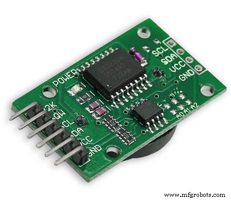
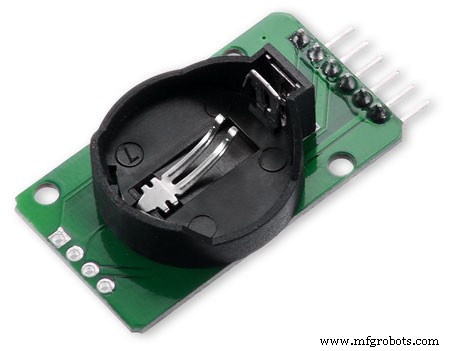
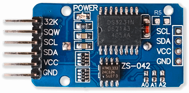
RTC DS3231 I2C 该模块存储来自解码 DCF77 信号的时间。内置时钟具有温度补偿功能,并在断电时具有备用电池。注意 RTC 模块被修改为使用不可充电电池。
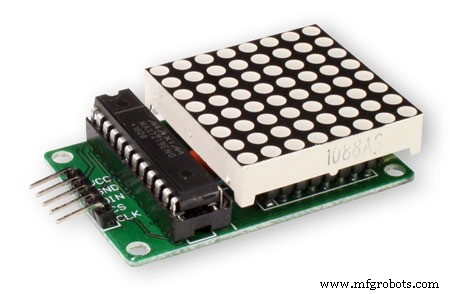
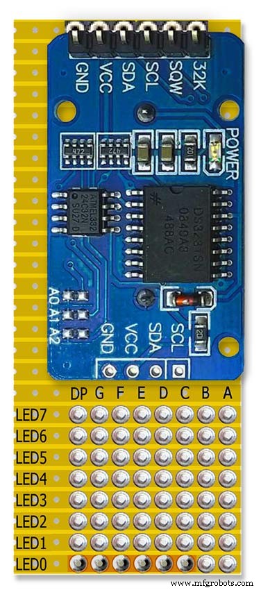
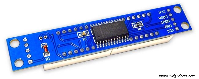
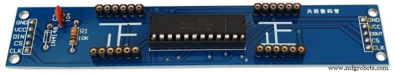
MAX2719 点阵模块这些模块驱动内部和外部 LED 环(2 个模块),第三个模块驱动所有其他 LED,包括超级过滤器 LED。移除 LED 矩阵并将 PCB 接头焊接到位。
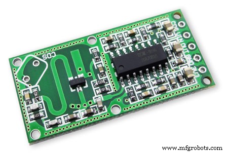
RCWL 0516 多普勒雷达传感器微波只有在房间有人时才打开时钟显示,我使用运动检测。您可以选择下面的 RCWL 0516 来检测玻璃后面的移动,或者下面的 PIR 模块。
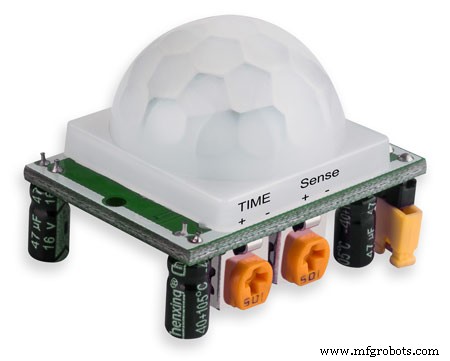
PIR 模块红外线可以使用 PIR 模块代替上面的多普勒雷达传感器。该设备的缺点是不能在玻璃或有机玻璃等后面使用。

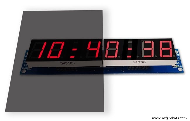
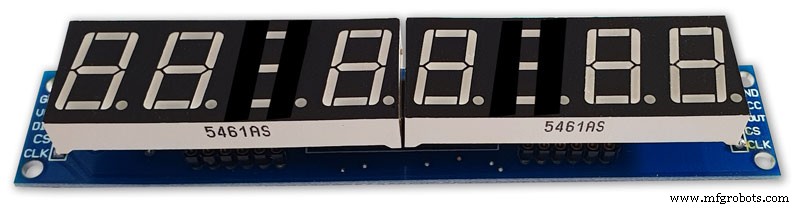
Max2719 7 段显示器 0.56" 这是用于时间和日期显示的较大 0.56" 版本。我已经有一批这样的,但 tindie 上有类似的模块。只需确保您使用的是更大的 0.56" 显示器。注意可能需要稍作修改以防止这些模块出现显示错误。请参阅 MAX2719 修改步骤。
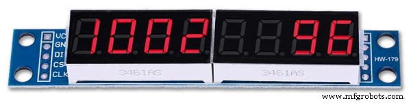
Max2719 7 段显示器 0.39" 这是用于位、错误和脉冲显示的较小的 0.39" 版本。它们在 eBay 和 Amazon 各处都有售,只需确保您获得的模块的插头引脚未焊接,或者引脚焊接到模块背面的电路板。请注意,可能需要稍作修改以防止这些模块上出现显示错误。参见MAX2719修改步骤。

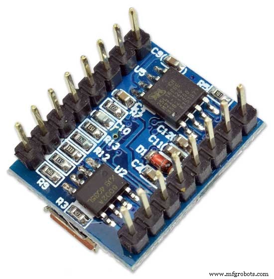
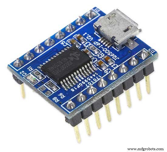
JQ6500 16p 模块这些模块中的一个用于播放滴答声,另一个用于播放刻钟和整点钟声。使用项目中包含的声音文件,您应该能够使用最便宜的 2M 内存的 16p 模块。每个模块驱动一个 3W 8Ω 扬声器。使用简单的程序通过 USB 从您的 PC(而非 MAC)加载声音。
DCF77接收机
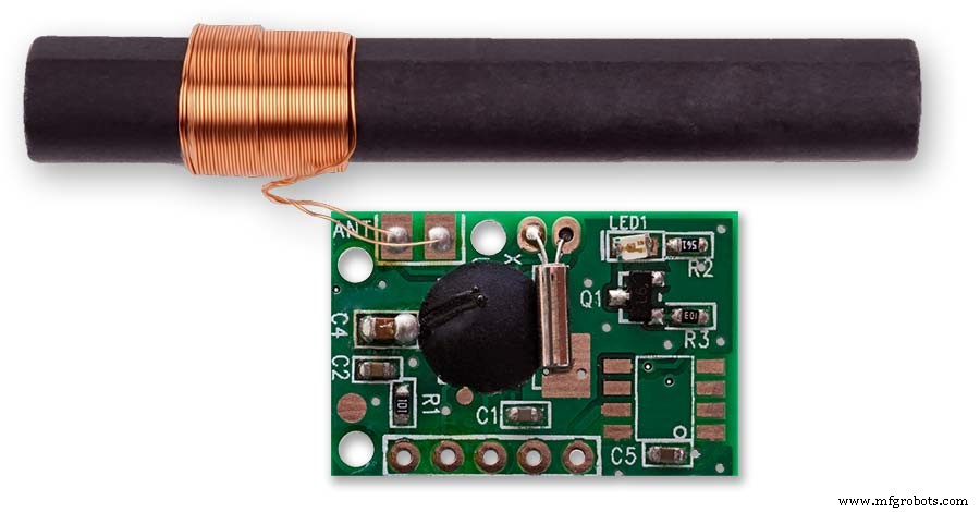
我的 DCF77 接收器模块来自 http://www.pvelectronics.co.uk
这些项目似乎不再可用,但请尝试亚马逊
PV Electronics DCF77 接收器模块连接 从左到右的连接
1.VDD 2.TCON 3.PON 4.GND 5.NC
提供反转格式的输出(输出低,每秒变高一次)。
低功耗待机模式 - 连接 PON 到 Vdd。
将 PON 连接到 GND 以正常工作。
使接收器远离电视、显示器或任何其他电气噪声,并确保其指向 DFC77 发射器。
组件
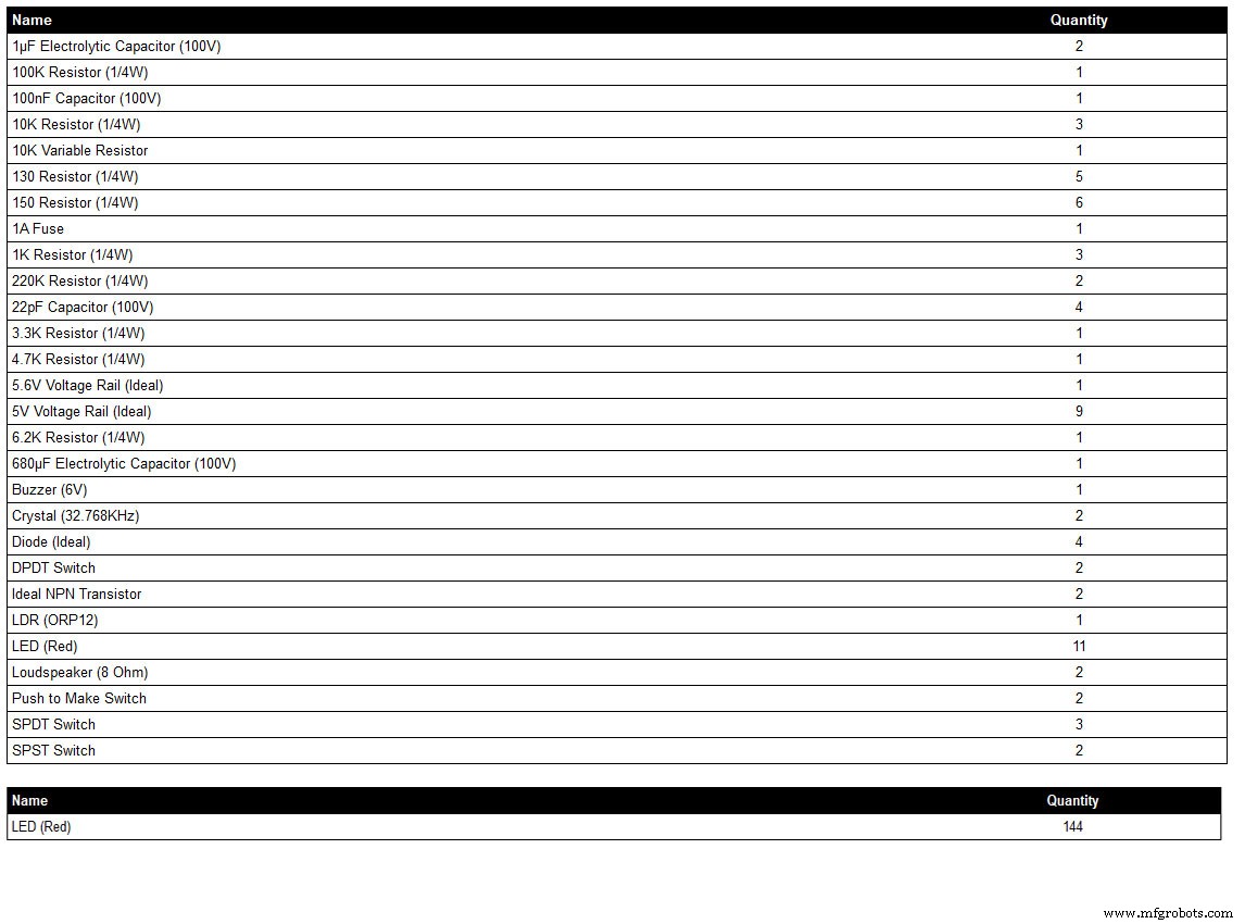
这是由我的原理图绘制程序 LiveWire 生成的组件列表,因此可能无法显示组件不在程序库中的完整细节,例如某些开关。查看原理图了解详情或联系我。
LED 颜色可以根据需要选择,但请参阅 LED 部分了解我使用的实际 LED。
第 8 步:接线顺序
大约有 400 多根电线连接布线,需要大量规划才能将布线安装在模块之间的间隙中。
如果需要,可以进行修改并将所有板固定到表盘后部,以便可以看到线束运行。
点阵板被移除并从时钟上接线。
连接超级过滤器 LED 并安装到表盘中。
为 DCF77 状态 LED 接线并装入表盘。
超级过滤器和 DCF77 状态 LED 通过接头电缆连接到主板。将点阵模块 3 上的所有 LED 接线并装入表盘。
从点阵模块 3 连接到小型分线 vero 板,然后连接到上述步骤中安装的该模块的 LED。
连接外部 LED 环,然后装入表盘。
为外环点阵显示器接线,使接线端足够长以终止在外环 LED 上。
重新安装外环点阵显示器并将线束端接到外环 LED 上。
连接内部 LED 环,然后装入表盘。
为内环点阵显示器接线,使接线端足够长以终止在内环 LED 上。
重新安装内环点阵显示器并将线束端接到内环 LED 上。
将点阵模块 3 上的所有 LED 接线并装入表盘。
从点阵模块 3 连接到小型分线 vero 板,然后连接到上述步骤中安装的该模块的 LED。
构建接头电缆并连接到所有板。
安装主 Vero 板,然后连接到开关面板。 LDR 是通过铰链木门安装的,开关面板固定在上面,因此可以同时接线。
安装扬声器并使用 JQ6500 音源连接到 Vero Board。
如果您在表盘上钻了正确大小的孔,则所有 LED 都会在没有胶水的情况下推入到位。在喷漆阶段确保 LED 孔的内边缘涂有油漆/清漆,以帮助摩擦配合。
第九步:接线Max2719点阵模块修改
在将电线连接到 MAX 2917 矩阵模块之前,需要对其进行修改。
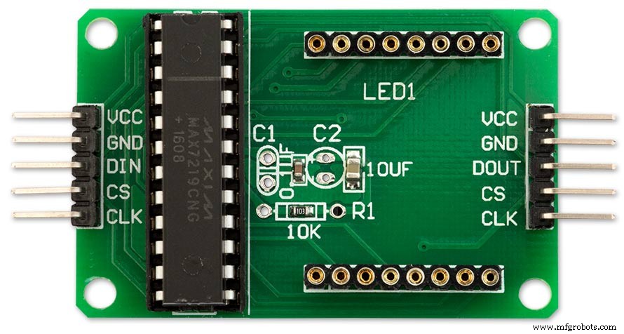
移除点阵 LED,因为它们不是必需的。
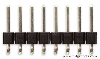
现有 LED 矩阵连接器的下边缘将焊接两组 8 90° pin 连接器。
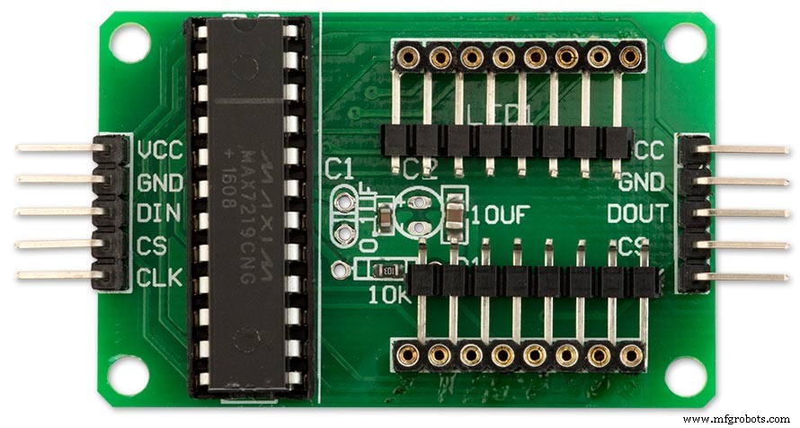
修改后的 MAX7219 模块带有 90° 引脚连接器,焊接到旧 LED 矩阵连接器的底部。从这些点到主板上的 LED 矩阵的电线被拆除。
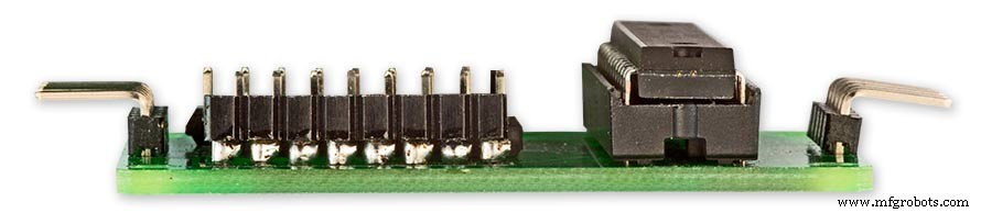
侧视图显示焊接到 PCB 正上方的旧 LED 矩阵连接器引脚一侧的引脚。
第 10 步:接线 构建接线夹具
夹具将以正确的间距将 LED 固定到位,从而可以轻松地从时钟布线。
为 LED 制作接线夹具
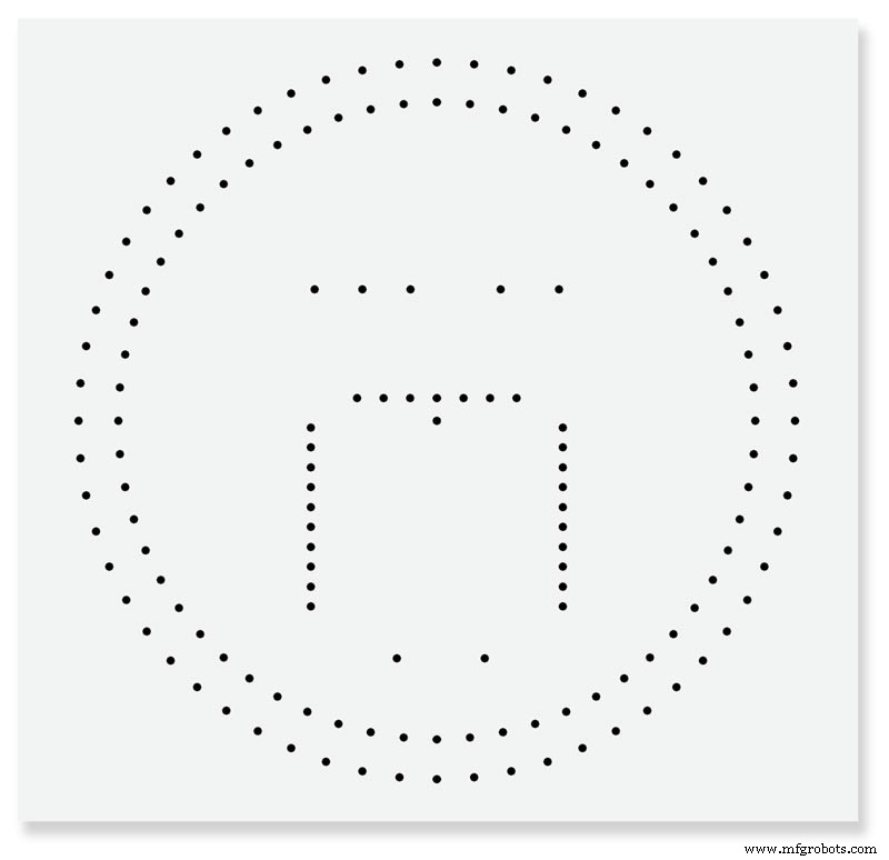
将表盘打印到一张纸上。反向打印或将纸张倒回正面,因为您将从时钟的后面工作。将床单放在一块旧木头或三聚氰胺上。中心冲所有 LED 中心并用 3 毫米钻头钻孔。该孔应与 LED 摩擦配合,以确保轻松接线。 LED 的直径各不相同,因此请先做几个测试孔,以获得适合您 LED 的正确尺寸。
完成接线夹具。
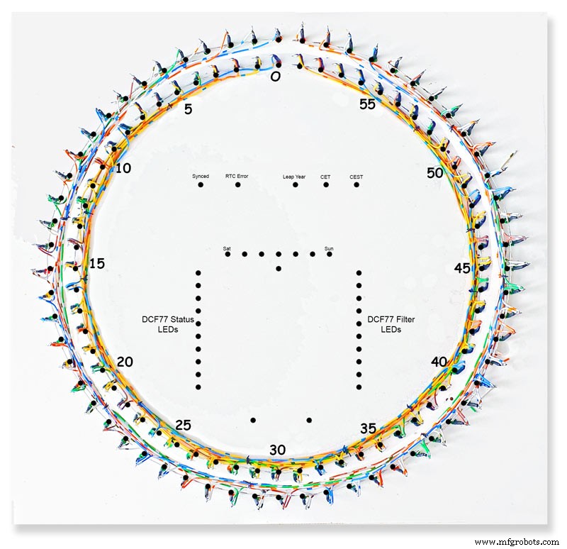
在夹具上完成内部和外部 LED 环。在夹具上写下 LED 编号和其他信息可能会很方便,因为 LED 安装在表盘后部并逆时针旋转。
从夹具上取下的 LED 环准备插入表盘。
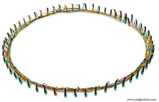
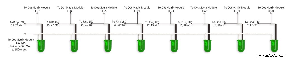
第 11 步:接线 LED 内圈和外圈
上图为LED外环的一段8个LED的接线示意图。
首先将八个 LED 推入夹具中的孔中。弯曲所有阳极,使它们按照外壳和焊料连接在一起。一根电线连接到 LED 矩阵模块的八个连接的阳极。在阴极上安装一小块绝缘套管,然后将这些腿弯曲到距 LED 约 15 毫米的位置。从弯曲处切下约 5 毫米,并焊接一段足够长的短线,以连接到下一批八个 LED。见图2。
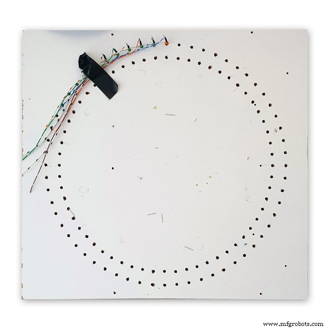
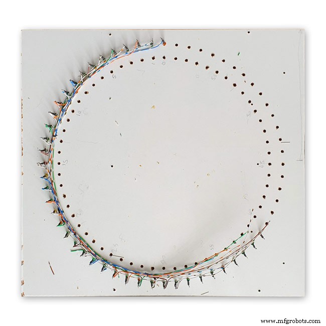
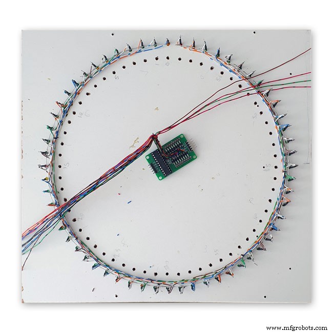
图 1 这显示了一个完整的 8 个 LED 连接在夹具上的部分,电线通向下一个 8 个 LED 的部分。
图2 8个LED分批重复上述过程。
每批 8 个 LED 都有自己的单独阳极连接到点阵模块。一共八个。
图 3 外环 LED 与点阵显示器的 16 根线连接完成。
然后将 LED 推入表盘上的孔中,并将矩阵模块固定回表盘上。一旦就位,来自点阵模块的 16 根电线连接到外环 LED。对内 LED 环重复此过程。
来自点阵模块的 16 根电线已准备好连接到 8 组 8 个 LED 部分。请注意,第 8 组只有 4 个 LED。完整尺寸的 4000x4000 原理图可以在这里看到。
LED
我在Ø 3 mm有色扩散封装中使用了Vishay TLH44系列高效LED
描述 TLH.44.. 系列是为标准应用而开发的,如一般指示和照明目的。它装在一个 3 毫米的有色扩散塑料包装中。这些设备的宽视角提供了高开关对比度。
提供具有不同发光强度的多种选择类型。所有 LED 都按发光强度组进行分类。这允许用户组装具有统一外观的 LED。
特点
• 标准Ø 3 mm (T-1) 封装
• 机械公差小
• 适用于直流和高峰值电流
• 广视角
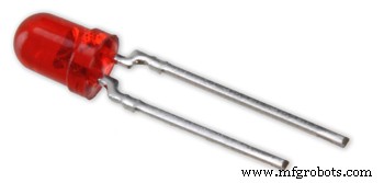
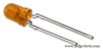
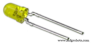
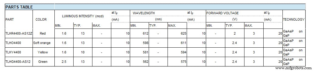
上图 1-4 显示了 LED 颜色,下图显示了带有实际零件编号的图表。
12:接线第三点阵模块
第三个点阵模块接线
该模块仅连接了 64 个 LED 中的 24 个。
8 个 LED 的第 1 节上的星期几 LED(仅连接 7 个)
8 个 LED 中的第 2 个是 CEST、CET Leap Yr、RTC Error、Synced、Error Period 和 Error Pulse Width(仅连接 7 个)
8 个 LED 中的第 3 个是缓冲区已满、奇偶校验 3 比 1 通过和失败以及缓冲区 Oveflow(所有 8 个 LED 都已连接)
8 个 LED 中的第 4 个仅包含 2 个 LED 分钟标记和 DCF77 状态
我本可以只使用 3 组 8 个 LED,但使用 4 组使接线更简单。
这些 LED 连接到接线夹具上,然后连接到一个小的 Vero 板上,在那里它们连接到矩阵线。请注意,此板还可用作 RTC 的安装座。
第 13 步:接线开关面板

开关面板在固定在检修门背面的时钟下方向下摆动。接线直接焊接到主板上,包括 LDR 的接线。

开关面板
开关面板接线进行中
安装在时钟底部的门上的开关面板和完整的接线机如图所示
使用从主板蛇行下来的开关的接线器完成接线。显示开关面板折叠到时钟盒中。
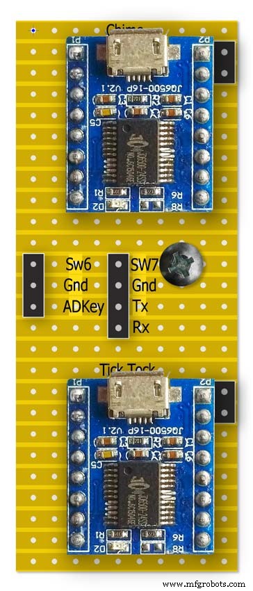
第 14 步:JQ6500 上的铃声和滴答声

该时钟使用 2 个 JQ6500 模块,一个用于滴答声,一个用于刻钟和小时钟声。滴答声由硬件控制,铃声由软件控制。
钟声电路
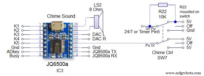
开关 SW7 是一个 3 位置锁定开关。该模块由 Arduino 上的串行硬件引脚 13 和 14 控制。注意接收电路上的 1K 电阻。见主示意图。关闭 - 从 JQ9500 中移除电源并且 24/7 /timer 引脚保持高电平以防止 Arduino 引脚悬空 24/7 - 钟声将响起四个季度和小时 24/7 定时 - 四季度钟声只会在 05:15 到 23:00 之间响起。 (在代码中设置)音量通过Arduino和Chime Volume上下开关在软件中设置。
滴答电路
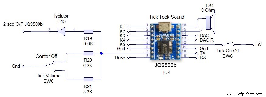
这是由硬件直接控制的 JQ6500 Switch SW6 Tick On/Off 只是移除 JQ6500 的电源。 Tick volume SW8 是一个 3 路中央锁定开关。向上或向下操作开关可通过 JQ6500 上的 ADKey 引脚设置音量。播放滴答声的命令每 2 秒从 Arduino 发送一次。声音文件必须少于 2 秒。二极管 D15 将 ADKey 与 Arduino 输出隔离。
第 15 步:演讲者
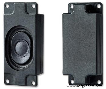
每个声音模块都连接到一个 3W 8Ω 扬声器,该扬声器连接在时钟外壳的侧面。这些可作为一对从亚马逊购买。
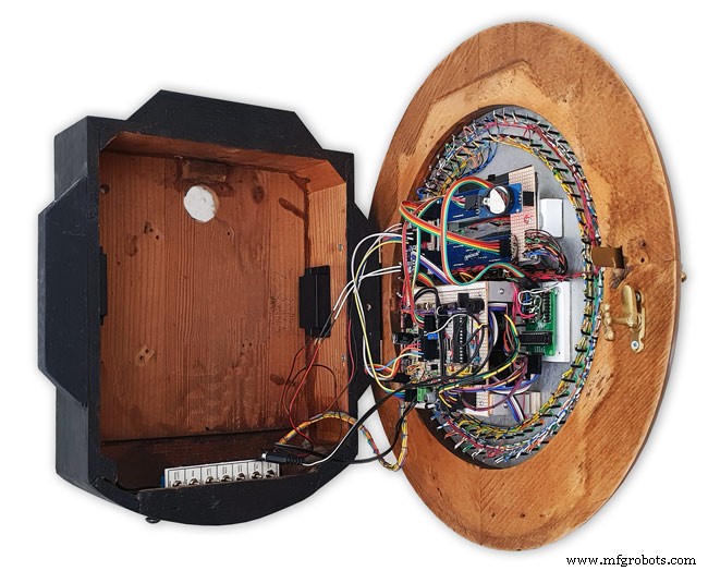
这张图片显示了时钟盒中的扬声器位置。注意时钟底部折叠起来的开关控制面板。
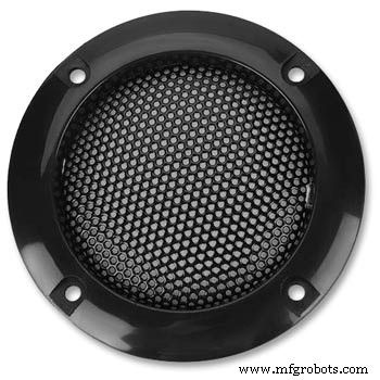
2 个扬声器格栅覆盖扬声器,同样来自亚马逊
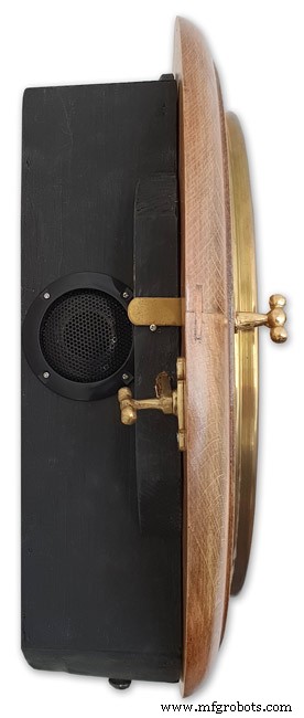
时钟左侧显示扬声器位置。这在另一边重复。
显示右侧扬声器的相框样式时钟。
步骤 16:JQ6500 加载声音文件
您的声音需要加载到 JQ6500 模块中。
请参阅这些站点以获取有关这些模块的信息和 Arduino 库。
Arduino库JQ6500_SerialGeneral infoJQ6500工具
通常 JQ6500 预装了一个音乐上传程序,该程序在连接到您的 PC 时加载(不适用于 MAC!)。这是中文版,我的网站上有说明如何使用中文版。
我的 JQ6500 没有加载程序,所以我从 Nikolai Radke 下载了英文版
You can get the zip file from here English Language MusicDownload.exe v1.2a
JQ6500_English_MusicDownload_V1_2a.zipI just run this file from windows (no need to install it) and it runs in English see details below.
Insert your JQ6500 into PC via USB.

When the file is run this window will open. Click FILES
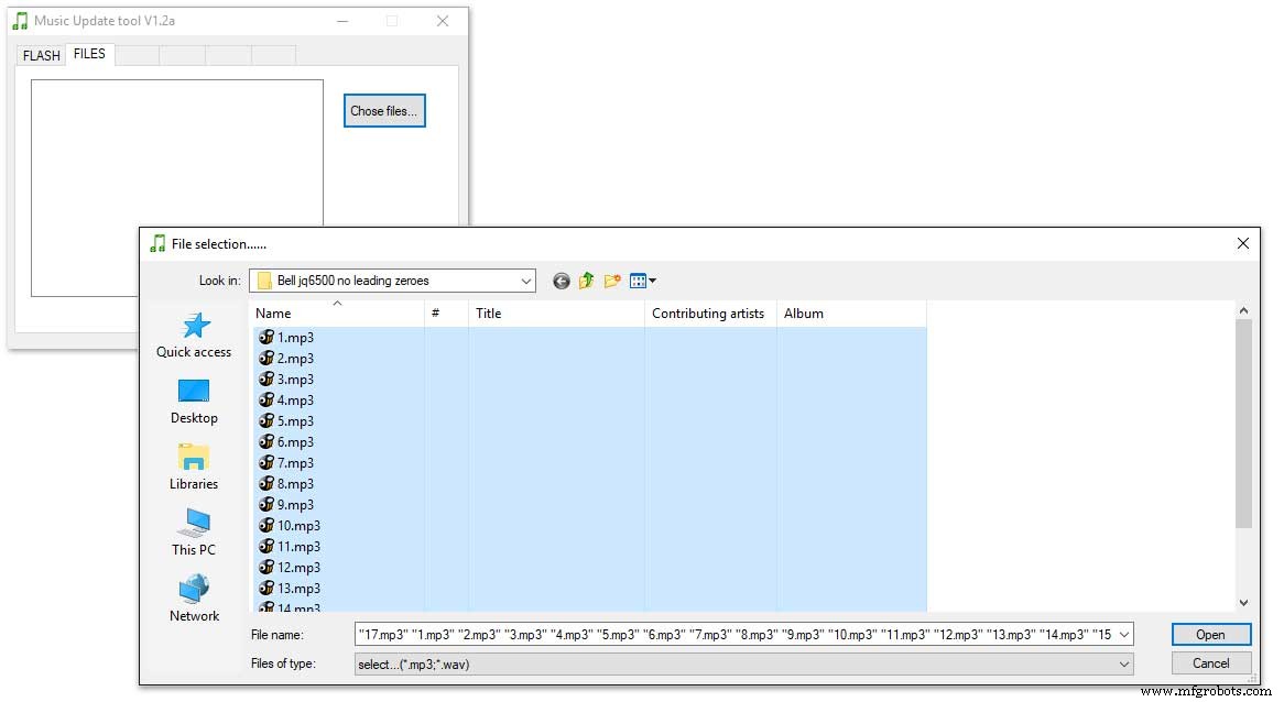
Click CHOSE FILES and shift select all the files you want to be copied to the module. Note make sure your files are named as below.
1 to 12 are the hour chimes. 13 to 16 are the quater chimes and 17 is the test chime used when setting the chime volume using the Chime Volume Switch.
Click OPEN above then click on the FLASH tab.
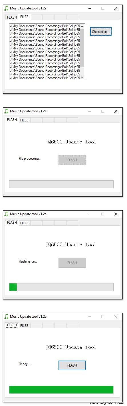
Click on FLASH and you should get a message saying FILE PROCESSING It the files will fit on the module the message will change to FLASHING RUN and a green bar will show progress.
When flashing is completed the message will change to READY......You can remove your module and plug it into sound board on the clock.
Repeat this for the Tick Tock sound (1 file this time) on the 2nd module.
Sound files are enclosed. I mixed these sound files up on Audacity pic 4 at 48KHz sample rate the max quality the JG6500 board can handle. The chimes were mixed on multiple channels to get the real harmonics then mixed back down to a single channel for the JQ6500.
bell.zip tick_tock.zip
Step 17:JQ6500 Library Modification
Modify the JQ6500_Serial.cpp file in your Arduino libray folder
Using the standard library every time a chime is played the library waits in case there is a reponse. This wait causes the clock run out of sync and any received data errors until the next minute.
I found this on google and is a reply from the author of the library. ~~~~~~~~~~~~~~~~~~~~~~~~~~~~~~~~~~~~~~~~~~~~~~~~~~~~~~~~~~~~ Before sending a command, the library waits for up to 10ms to see if there is any left over data from the device... https://github.com/sleemanj/JQ6500_Serial/blob/ma... after sending the command the library waits for a response for up to 1000ms
https://github.com/sleemanj/JQ6500_Serial/blob/ma... and after that it will wait at least 150ms while reading the response
https://github.com/sleemanj/JQ6500_Serial/blob/ma... since in the case of playFileByIndexNumber you don't need a response at all
https://github.com/sleemanj/JQ6500_Serial/blob/ma... you could perhaps get away with adding if(!responseBuffer &&!bufferLength) return;immediately after the last command byte is written (currently line 263 of JQ6500_Serial.cpp)
https://github.com/sleemanj/JQ6500_Serial/blob/ma... that should reduce the time required to about 10-20ms probably.
~~~~~~~~~~~~~~~~~~~~~~~~~~~~~~~~~~~~~~~~~~~~~~~~~~~~~~~~~~~~~~~~
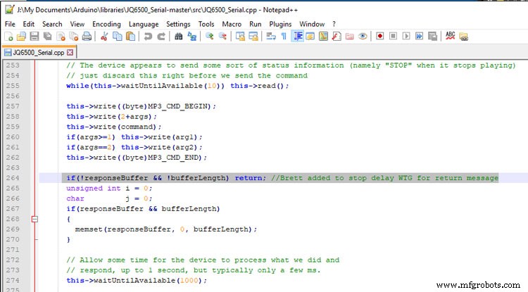
After adding the line after line 263 if(!responseBuffer &&!bufferLength) return; the clock worked fine.
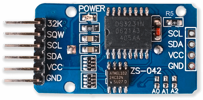
Step 18:Modify the Real Time Clock RTC
Modification of DS3231 AT24C32 I2C Precision Real Time Clock Module
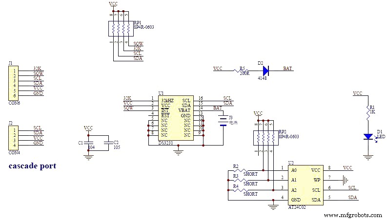
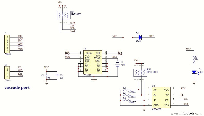
My clock uses a DS3231 AT24C32 I2C Precision Real Time Clock Module.The module comes supplied with a Lithium-Ion rechargeable battery see pic 1. I use a non rechargeable battery so have removed resistor R5 from the module as pic 2.
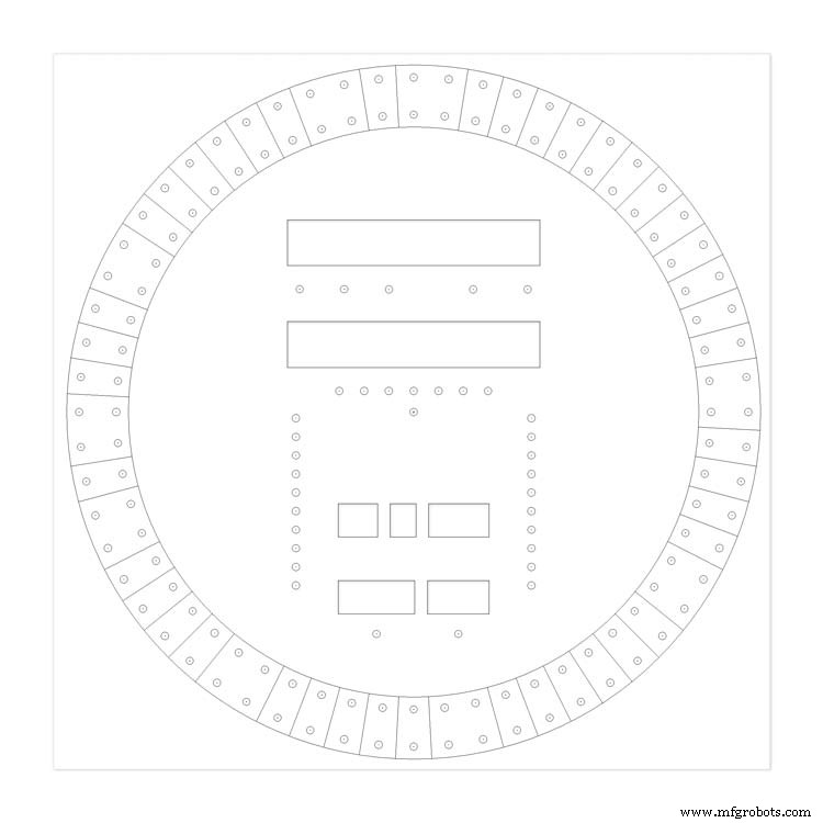
Step 19:Dial Construction Drawing
The dial requires oround 700 seperate drilling operations and numerous aounts of cutting and filling to complete.
I don't have a CNC machine so it was all done by hand.
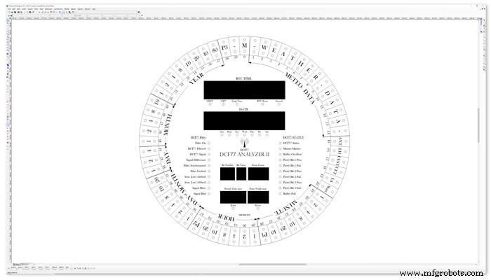
The dial was drawn up on a Cad program (TurboCab) pic 4 and printed out onto injet water slide decal paper.
This shows a close up of dial printing with 3mm LEDs to give an idea of scale. The quality from the water slide decal paper is very good far better than my old ink jet can print.
The enclosed zip file contains the dial picture in various file formats including a 4000x4000 png file.
Contact me for other file types!
TurboCad_Drawings.zip
Step 20:Dial Construction Cutting Out &Drilling
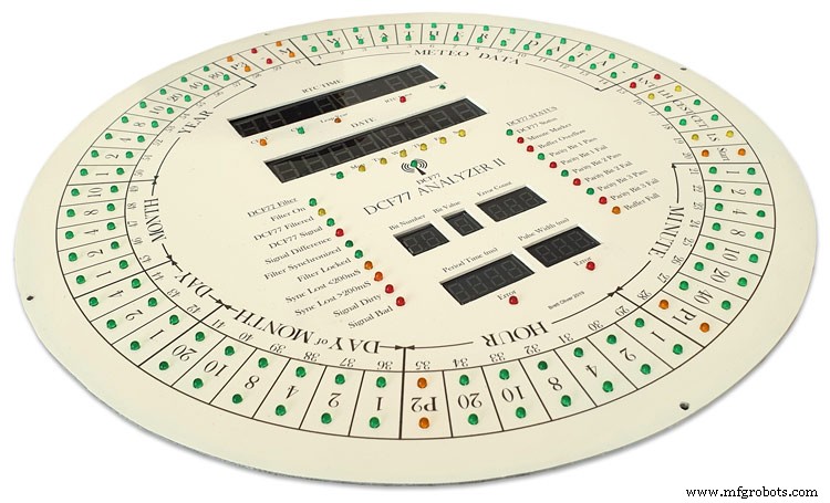
The dial is cut from 1.5mm thick alluminium sheet as it has to carry the weight of all the electronics and wiring.
Make a template by printing out the dial from your CAD program onto A3 paper.Make sure it has center marks for the LED holes and also the cutouts for the 7 segment LED displays.
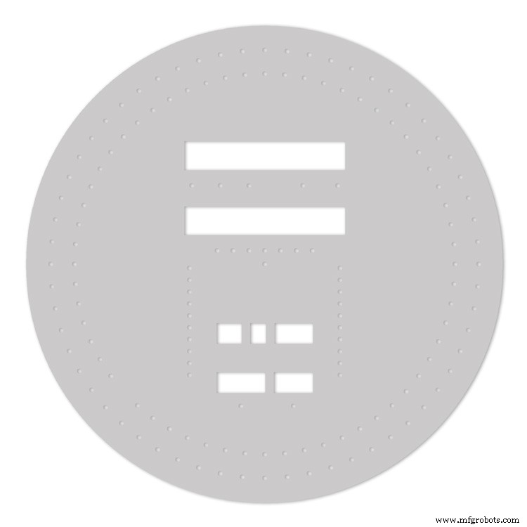
Carefully cutout the 7 segment display openings on the template with a craft knife.Place the template on the alluminium sheet and tape it down to stop it moving. Center punch all the center marks for the LEDs and draw around the openings for the 7 segment displays with a marker pen.
Remove the template to reveal the cutting/drilling marks on the alluminium sheets protective film.
Draw a circle the size of your dial with a compass using the center punch mark from the DCF77 symbel LED as a center point.
Cut out the circle with a hacksaw/jigsaw or bandsaw fitted with a metal cutting blade.

Cut out the 7 segment display openings with a coping/jig or fret saw. Take your time with this as it will save a lot of filing later.

Drill out all the holes for the LEDs. I start with a 1mm bit then a 2mm and then finally a 3mm bit.
This leaves the LEDs a friction fit once the paint and varnish is applied to the dial.
Mark center punch and drill 3 or 4 dial mounting holes.
With the holes drilled the protective film can be removed from the alluminium sheet and the dial rubbed down to remove all rough edges.
This will also give a good key for the paint.
Prime and paint with acrylic paint then a coat of matt varnish. Antique White looks better on old dials or use pure white on modern dials.
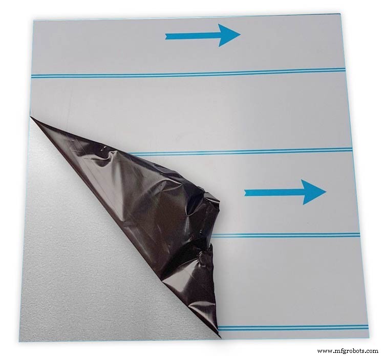
Step 21:Dial Construction Applying the Dial Transfer Decal
Water slide decals are printed out on special paper on an inkjet printer. Once dry they are soaked in water then slid into place.
They give a very detailed print and once given a coat of varnish are tough. Don't forget to order transparent tranfers so the dial colour can be seen through the transfer. Follow the instructions with the pack as they do vary.
On my transfers I print out the dial on transfer paper let it dry and then cut it out to just under the size of the dial. I then give it a coat of acrylic varnish. When the varnish is dry the transfer is soaked in water until the transparent transfer comes away from the white backing sheet.
Line up the transfer with the dial and slide it over the dial.
Make sure the center dots line up with the center of the holes in the dial then slide the backing sheet back off the transfer.
Carry out any final adjustments then remove any airbubbles.
Allow to dry then apply some clear acrylic varnish to protect the transfer. Once this dries carfully cut away the transfer around the 7 segment display cutouts with a craft knife. Then cut the transfer off all the LEDs hole. I used a leather punch just smaller than the hole. Give it another coat of varnish to seal all the cut edges Leave it overnight to dry.

Search for "Transparent Water Slide Decal Paper A3"
Step 22:Dial Construction PCB/Vero Board Mounts
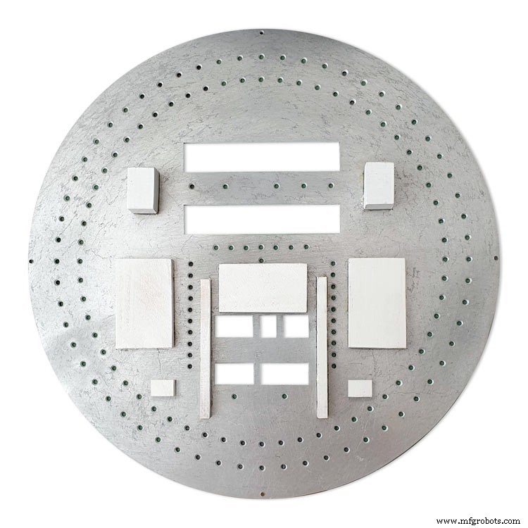
The PCBs and Vero Boards are fixed to wooden mounting blocks cut from off cuts of timber.These block are glued to the dial with impact adhesive. Follow the instructions on the impact adhesive but normaly you apply to both surfaces leave until tacky then press together for an instant bond that hardens fully over night.
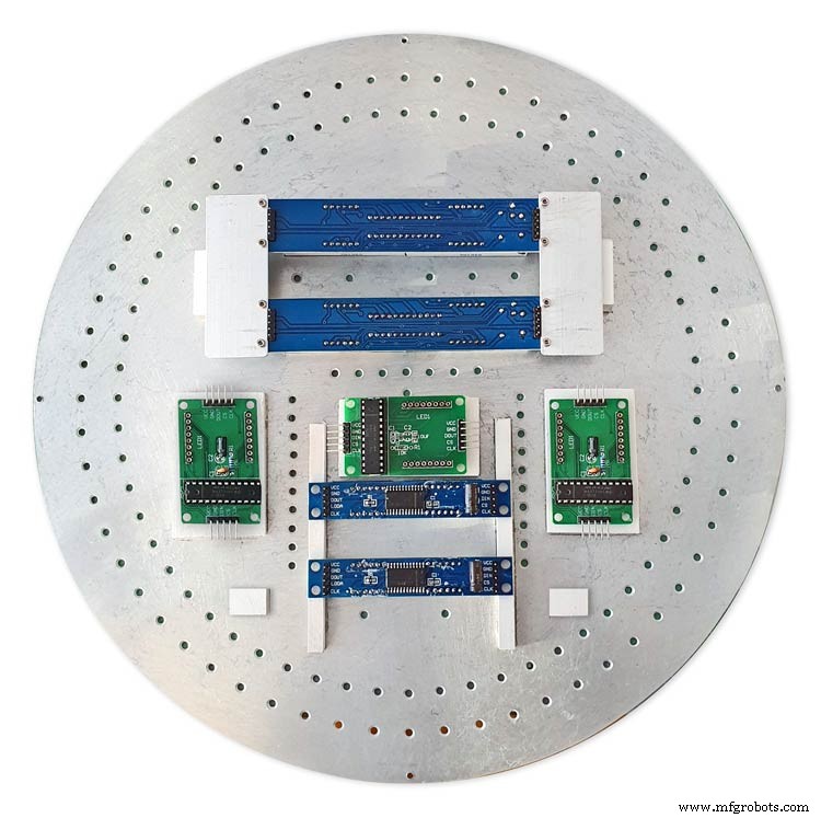
Lower modules in position on the wooden blocks ready to be secured by M2 screws.The main PCB fits on top of the lower 7 segment modules and is raised up on brackets.
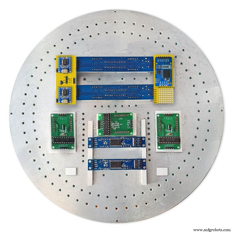
JQ6500 sound module board and LED wiring board in place. RTC is mounted on the LED wiring board but connected on the main board.
Main board mounted on custom made standoff brackets.
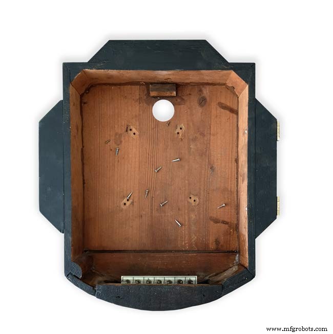
Step 23:Dial Surround &Back Box Restoration
Dial Surround Restoration
I sourced my clock case from eBay. It had no dial or brass bezal and the rear box was broken.
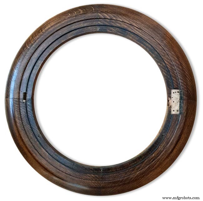
The original Oak dial surround was covered in a thick coat of varnish and years of dirt.
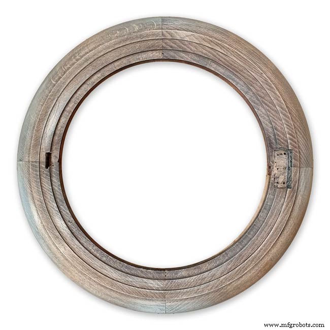
I used paint stripper to remove the varnish and then wood bleach to get rid of the very dark areas of wood.
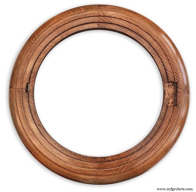
The surround was then varnished with matt acrylic to enhance the grain of the wood.
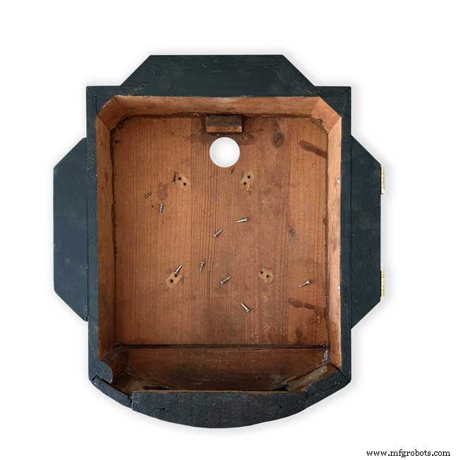
The back box was very badly damaged and had to be screwed and glued back together. I has to fill many hole and cracks in the wood work and decided to paint it matt black.
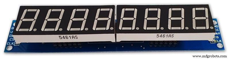
Step 24:Correcting MAX7219 7 Segment Module Display Errors
The 7 segment modules seem to work fine work fine on their own. However, once you start daisy chaining them together the displays tend to error.
0.39" Display

The datasheet calls for a 10μF and 0.1μ capacitor across the supply rails as close to the MAX7219 as possible.I notice the 0.1μF capacitor is in place but the 10μF capacitor is missing.
Add this capacitor in the 2 holes above the diode D1 on the rear of the display.

There is also a diode in series with the supply rail. When daisy chaining modules all these diodes are in series so the further down the line of modules the more volts are dropped causing display errors.
Remove this diode on each display and replace it with a wire strap.
0.56" Display
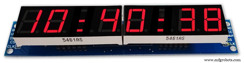
Note the black tape over the 3rd and 6th digit tp make colons.
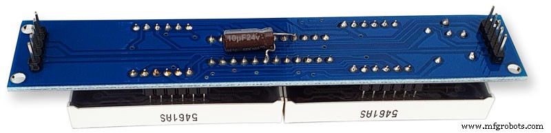
10μF capacitor added to the rear of the PCB on the +&- pins of the MAX7219 IC
The 1N4148 diode is replaced by a wire link.
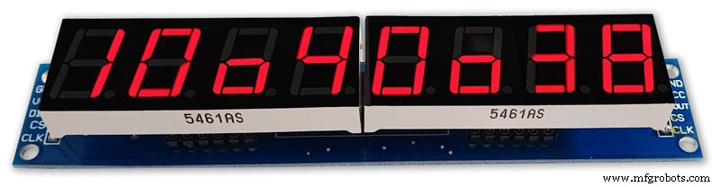
Step 25:Increasing the Constrast on the 7 Segment Modules
The 7 segment displays traditionally would have a sheet of red perspex to match the LED colour placed over the top of the display. This was designed to hide the not lit segments and provide contrast to the LED segments that are on.
In my clock I have used Neutral Density Heat Proof Dimming Transparent Acetate Sheet ND 0.9.
This hide the not lit LED segments and provides the contrast needed in bright conditions. It has the advantage that it work on all colour LEDs.
My 0.56" modules are a deeper red than the 0.39" modules so I would need 2 different matching red perspex to sheets to work well on both modules.
The acetae shhet is also very cheap the only disadvantage is that it is too flimsy to cover large areas without support.
The picture above shows the effect of the ND sheet. The lit LED segements have more contrast and the unlit LED segments are hidden. It also hides the black tape masking for the colon display.
Step 26:Modification of the RTC Time 7 Segment Display Module to Show Colon Digit Seperators
The standard display only has decimal points to separate the digits and has no colon that would normally be used in a clock display.
In code I have set digits 3 and 6 to always display a "o" lower case o
Black plastic tape is then cut with a craft knife and placed over the 2 digits leaving a small section showing

When the display is on these visible sections now display colons
Step 27:Dial &Case Fitting
The dial is hidden behind a brass bezal. The brass bezal was missing from my clock but I was able to get one from a horological supplier.
The brass bezal is held down by a brass catch set into the dial surround.

With the brass bezal removed you can see the recess cut in the surround for the brass bezal hidge. My new bezal hinge was a differnet shape to the original hinge so I had to cut it in with a chisle at the front and fill the rear in with a piece of wood stained to match the surround.
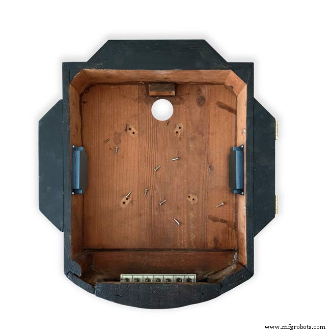
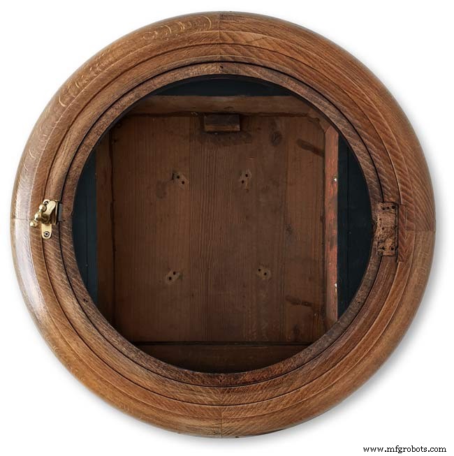
The dial has been removed showing the dial mounting holes on the wood surround and the wooden back box behind it.
Shows the surround removed revealing the back box construction. The switch panel can be seen folded up above the trap door in the base of the back box.

Shows the side view of the case with dial and wood dial surround locked in place. The dial surround is locked by the same type of catch used to lock the brass bezal in place. Note the small brass screw below the brass tag on the dial bezal. this ensurse the brass bezal lines up correctly with the dial when the brass bezal is closed.
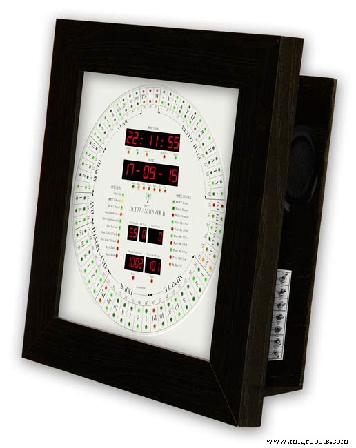
Step 28:Dial &Case Fitting Modern Style Case and Surround
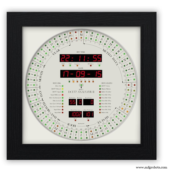
This case uses a large picture frame with a basic square back box to hold the electronics and to hold the dial away from the wall to give it some depth.
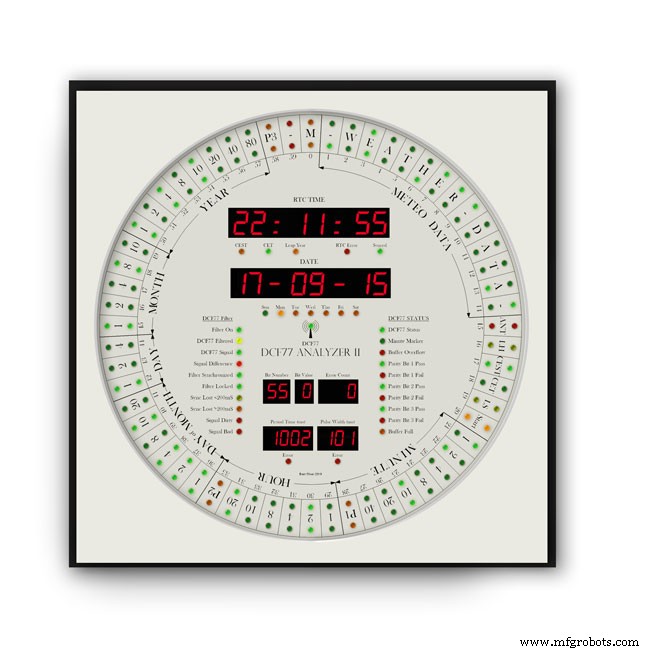
Outer frame and glass removed to reveal the thick photomount card over the dial (a thin ply or wood sheet can also be used with a routed edge)
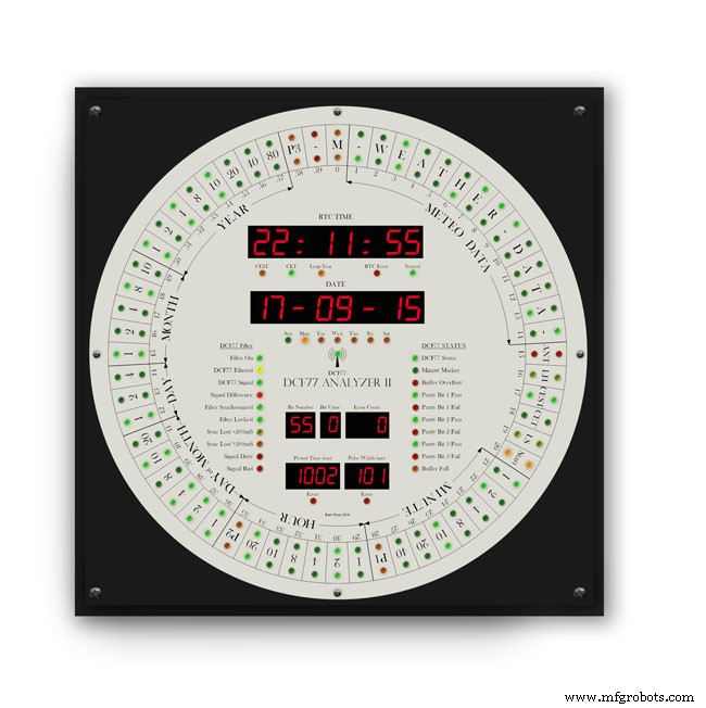
Photo mount removed to show how the dial is fixed to the back plate with 4 small screws.
The backplate holds the dial and has a large circular cutout for the electronics.

It is hinged at one edge to the dial can swing out.
The speakers are mounted on both sides with holes and grills as per the other case.

The switches are mounted on the side in a cutout with the speaker grill above.
Step 29:DCF77 Filter
DCF77 Filter
When switched on the Udo Klein's Super Filter actively processes the incoming DCF77 signal from the antenna/receiver. After a few minutes of sampling the DCF77 signal the Super Filter will predict the DCF77 signal and use this to determine if the incoming signal contains any errors. The Super Filter will then synthesize a corrected DCF77 signal even if the signal is absent.
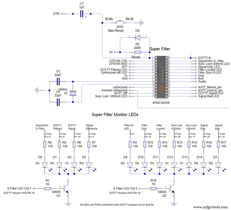
Super Filter Mod See the schematic. I have modified the Super Filter Code to add extra monitor LEDs. In order to do this I have removed 4 modes from the filter just leaving sythesized and inverted sythesized.
Note the PWM LED brightness control is via the Arduino controlling the DCF77 decoding not the Super Filter Arduino. I have also added an LED test to the Super Filter to Match the LED Test on the main clock. This activates on reset or power up. On power up the Supe Filter LED test starts and finishes then the main clock LED terst starts.
The filter will lock onto the DCF77 signal even if the signal is really noisy. As days progress the filter uses the incomming DCF77 signal to adjust the Arduino crystal frequncy.
This means the filter will stay in time even if the DCF77 signal is lost for many days. In my clock the DCF77 signal is alway fed to the Super Filter Arduino even if the DCF77 Source switch is set to off. This allows the Super Filter to stay in sync and keep adjusting the quartz crystal from the Arduino.
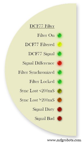
Filter On lights when the DCF77 Source switch is set to FILTER and means the Super Filter is decoding and synthesizing the DCF77 signal
DCF77 Filtered the DCF77 Synthesized signal comming out from the Super Filter
DCF77 Signal the DCF77 signal comming direct from the DCF77 receiver with no filter applied
Signal Difference the differnece between the incomming DCF77 signal and the Synthesized signal. In normal operation this will flash as the received signal shape is often slightly “wider” than the synthesized signal.
Filter Syncronized best possible quality, clock is 100% synced
Filter Locked clock driven by accurate phase, time is accurate but not all decoder stages have sufficient quality for sync
Sync Lost <200mS clock was once synced, inaccuracy below 200 ms, may re-lock if a valid phase is detected
Sync Lost>200mS clock was once synced but now may deviate more than 200 ms, must not re-lock if valid phase is detected Signal Dirtytime data available but unreliable Signal Bad waiting for good enough signal
More details on some of the above
Filter Syncronized - Timing is completely locked to DCF77 and the data is most up to date.
Filter Locked - If the quality factor of the decoder stages drops but the quality factor of the phase decoder stays high enough the clock will transition into the state locked. In this state it is still phase locked to DCF77 but it may become out of sync by a second but only if a leap second is transmitted.
Sync Lost <200mS - This indicates that the quality factor of the decoder stage and the quality factor of the phase decoder have dropped. In this state the timer relies on the quartz crystal timimgs and the clock will slowly drift out of phase with the DCF77 signal. This is a warning that the clock may be running slightly out of sync.
Sync Lost>200mS - Once the clock has started to drift out of phase for more than a set period of time (depending on the tuned accuracy of the quartz crystal) then this LED will light
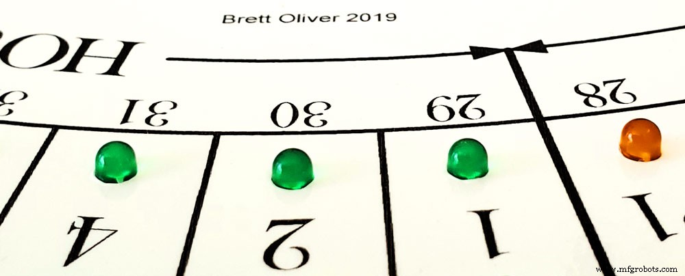
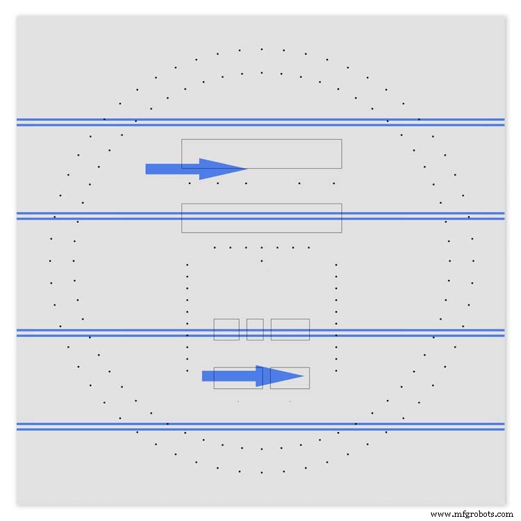
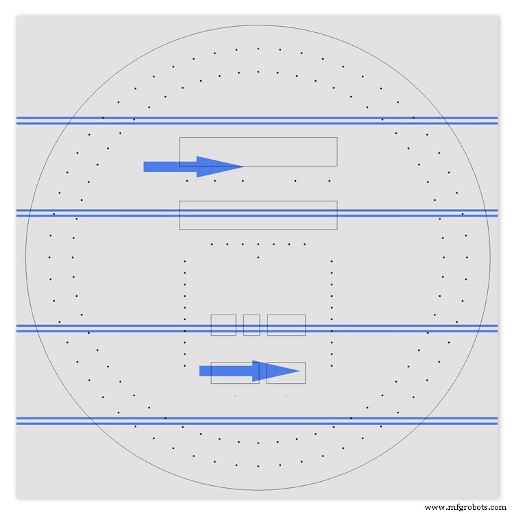
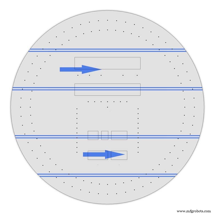
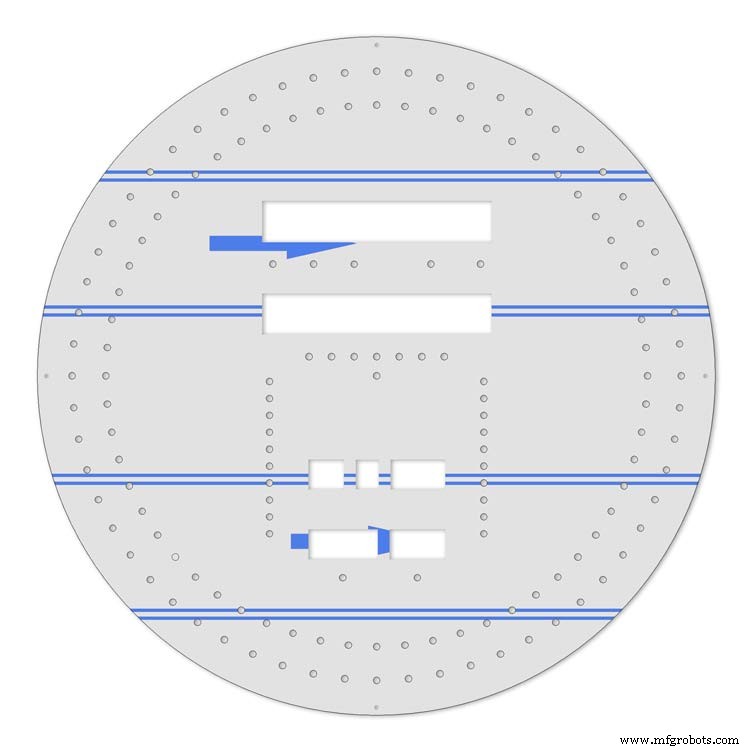
Animation showing filter synchronized
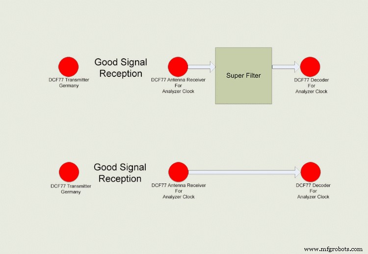
Super Filter example
The top row shows the Super Filter turned on. Once synchronized and tuned into the signal the Super Filter will synthesize a good signal even when the signal is completely lost. On a noisy signal the Super Filter will search for known signal bits and keep itself synchronized to the transmitter. The bottom row shows the Super Filter turned off. Whatever signal is received (good or bad) is sent to the decoder.
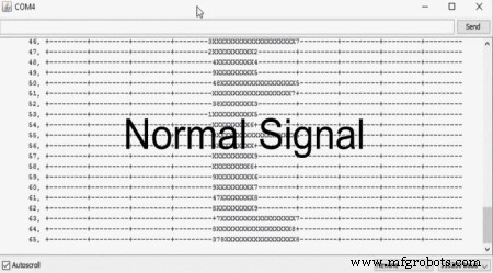
Super Filter correcting a noisy signal as displayed on the DCF77 Scope included with the DCF77 library.
Normal Signal No super filter - Normal signal from the DCF77 reciever Noisy
Signal No Super Filter - The aerial is moved near a LCD screen to generate noiseover the signal
No Signal- The aerial is disconnected and moved connected via the super filter
Noise On Superfilter On- The noise is filtered out leaving a perfect signal.
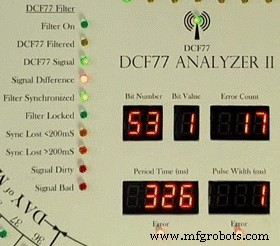
Super Filter turned Off and a bad signal the clock errors and will reject this minutes data.Note the DCF77 Filtered LED pulses as normal but as the Filter is turned off the filtered signal is not fed to the clock's decoder.
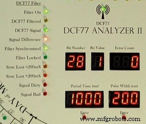
Super Filter turned On and a bad signal the clock has no errors and the clock is able to decode the data as normal.Note the DCF77 Filtered LED pulses as normal and is fed to the clock's decoder
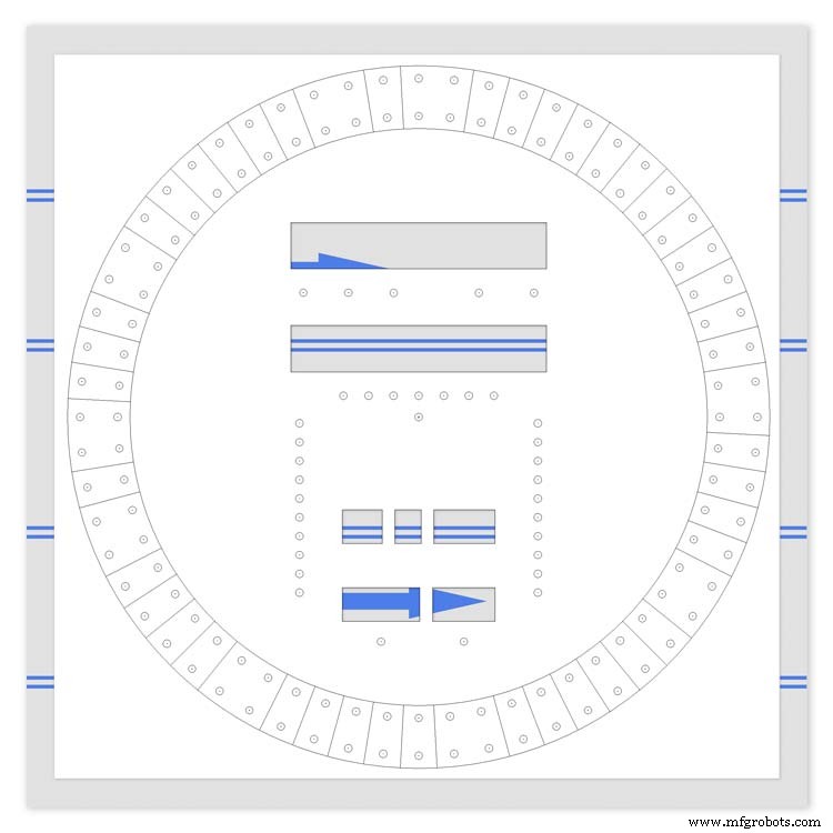
Step 30:DCF77 Time Code
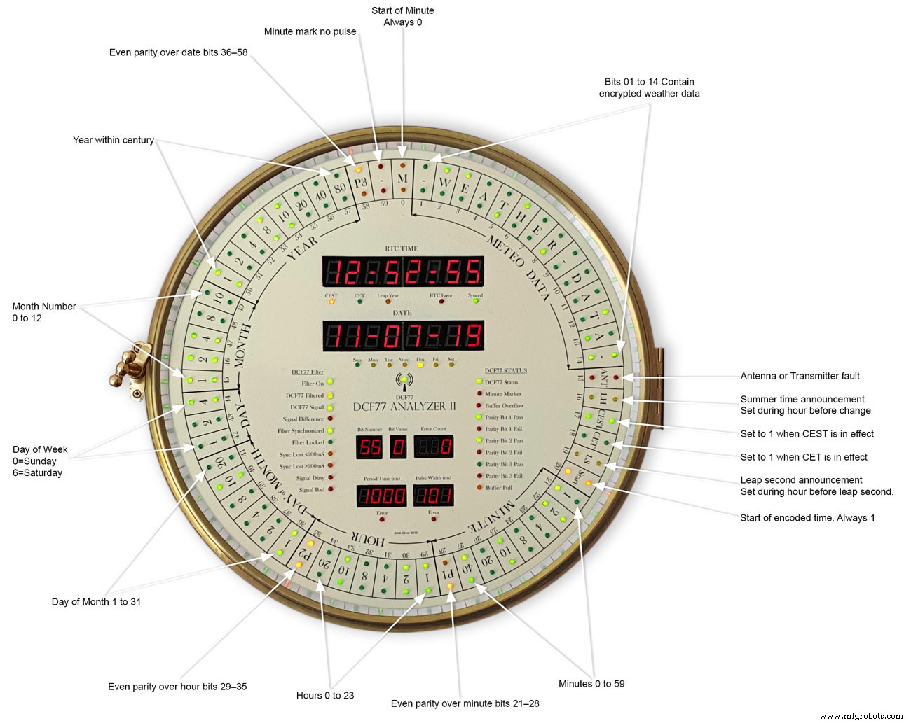
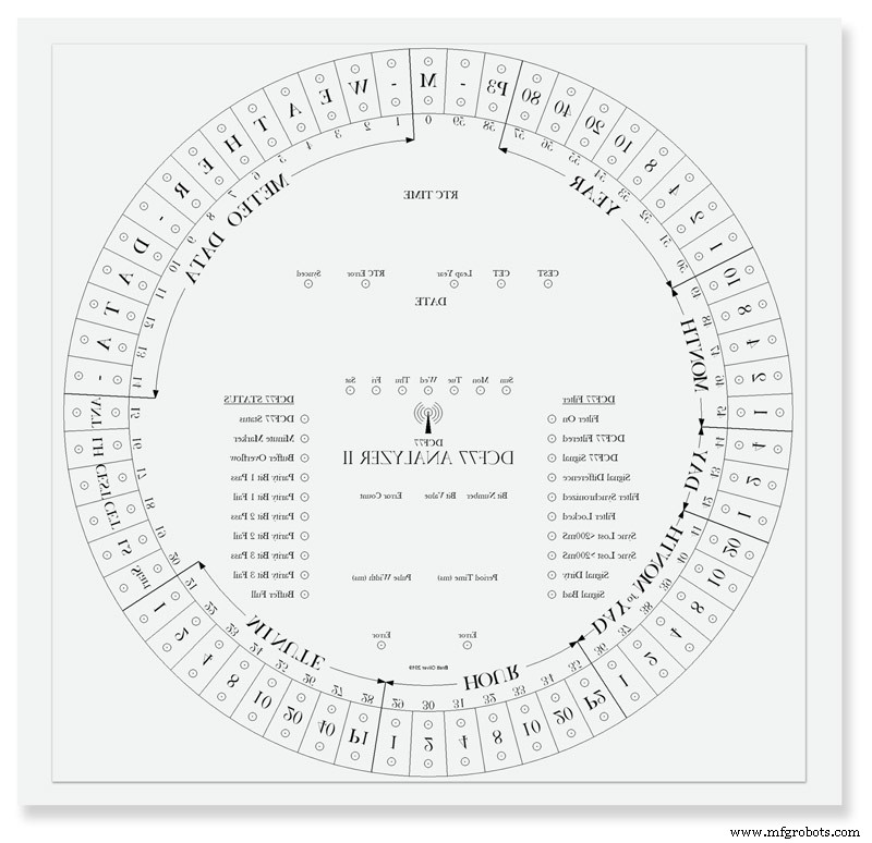
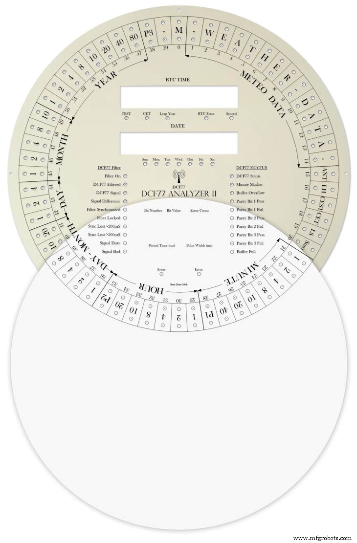
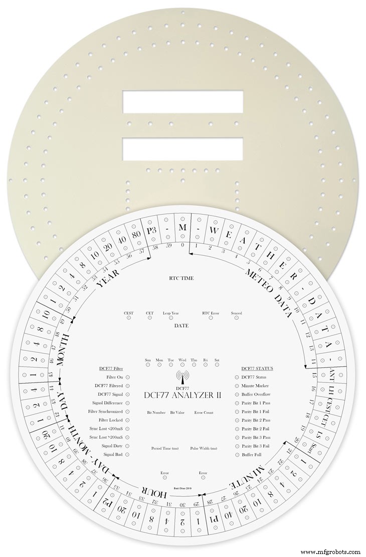
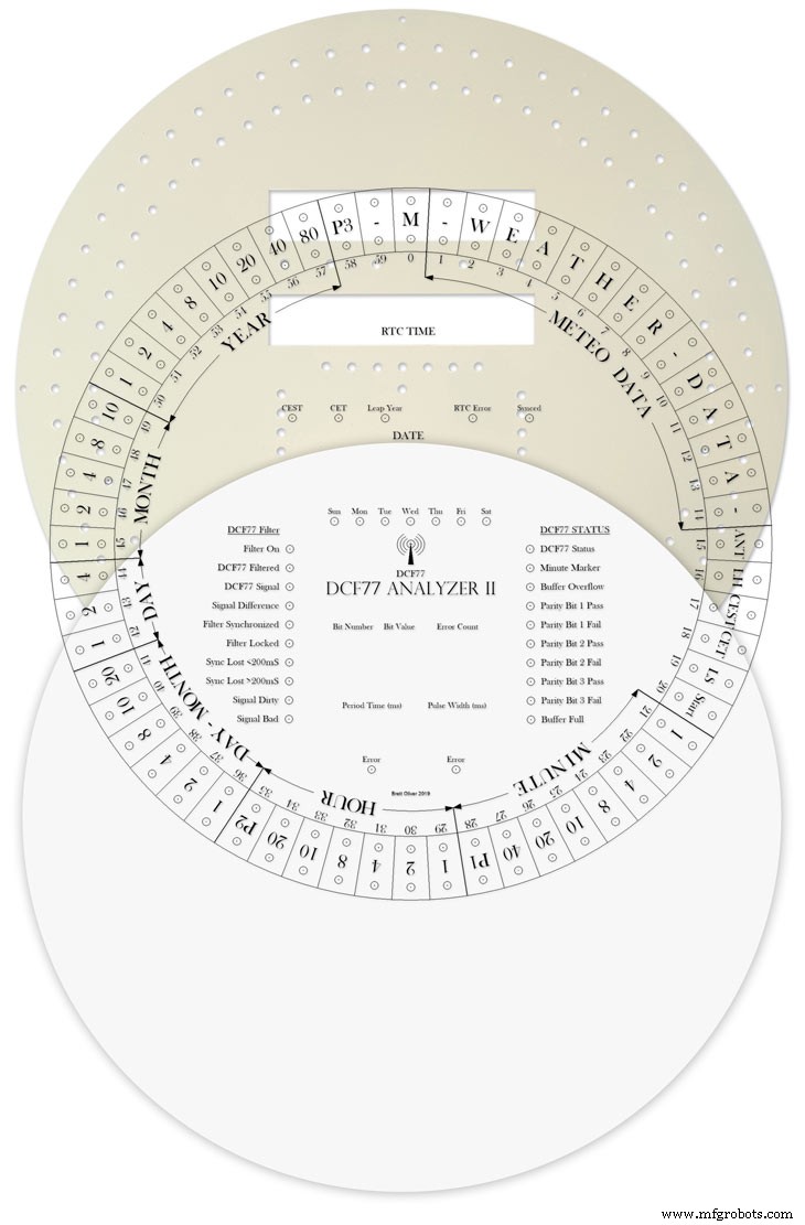
This picture shows the dial code as it is displayed on my dial and allows you to read the incomming DCF77 signal.
Step 31:Code
There are 2 seperates codes to download one for the Superfilter and one for the Analyzer part of the clock.
DCF_77_ANALYZER_CLOCK_Mk2_43.zip Superfilter07DCF77AnalyzerMK2.zip
代码
- DCF77 Decoder Code
- Super Filter Code
DCF77 Decoder CodeArduino
This is the code loaded onto DCF77 analyzer ArduinoNo preview (download only).
Super Filter CodeArduino
This is the code loaded onto DCF77 Super Filter ArduinoNo preview (download only).
Github
https://github.com/sleemanj/JQ6500_Serialhttps://github.com/sleemanj/JQ6500_Serial定制零件和外壳
CAD files for the dial and dial template in CAD formats and also picture files turbocad_drawings_TESmpq119g.zipSound files for loading into the JQ6500 module for chimes bell_wYLvJG1pUl.zipSound files for loading into the JQ6500 module for tick tock sound tick_tock_FLj9XHTJoB.zip示意图
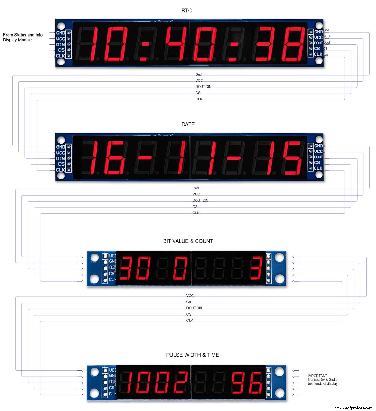
This is the main board schematic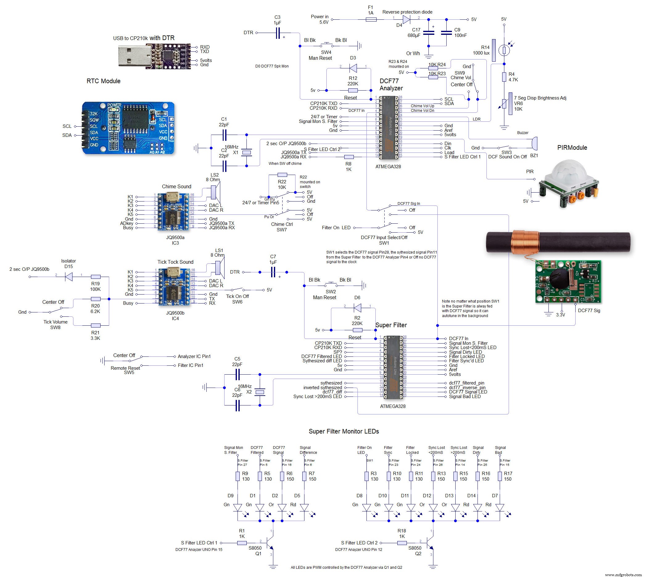 This is the schematic to show the MAX7219 dot matrix module wirng to the LEDs
 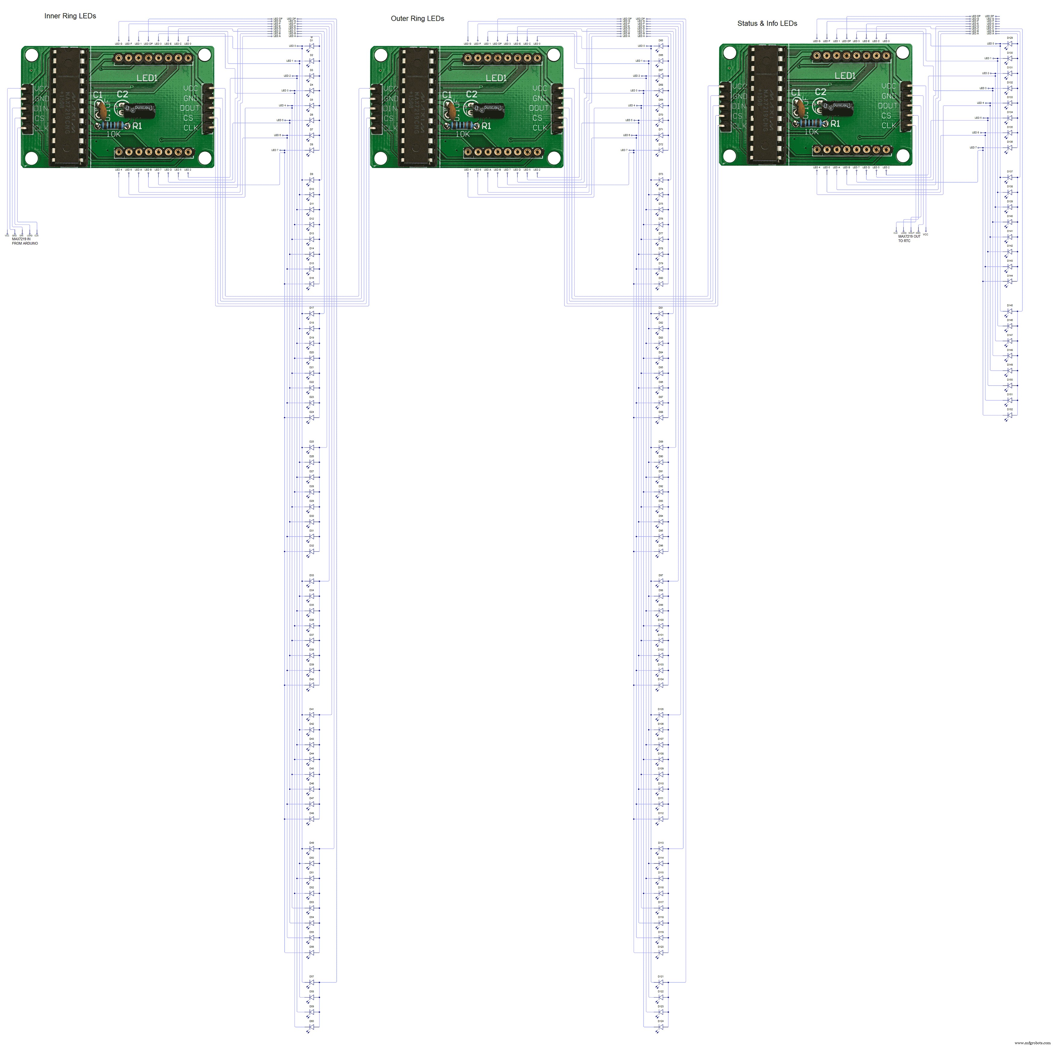 This shows the wiring for the MAX7219 7 segment display modules
制造工艺