

老年痴呆症助手
组件和用品
 |
| × | 1 | |||

| × | 1 | ||||
| × | 1 | ||||
 |
| × | 1 | |||
 |
| × | 1 | |||
 |
| × | 1 | |||
 |
| × | 1 | |||
| × | 1 | ||||
| × | 1 | ||||
| × | 1 |
必要的工具和机器
 |
|
应用和在线服务
 |
| |||
 |
| |||
 |
|
关于这个项目
这些直接引用自阿尔茨海默氏症协会网站(2017 年 9 月)的事实足以让任何人了解一个人或他们所爱的人患有阿尔茨海默氏症时必须经历的问题。
作为一名创客,我考虑了这一点,并决定开发一个可穿戴设备,一个可以帮助患者及其看护者的系统。
该系统至少应该能够执行以下任务:
- 提醒患者执行任务,他/她每天必须做的事情(例如药物、锻炼等)
- 监控患者在家中的位置
- 在出现任何紧急情况时提醒看护人
- 显示时间(毕竟是手表!)
- 它应该是便携且易于使用的,即使对于老年患者也是如此
- 成本应保持在最低水平
当我看到英飞凌的 Sensor Hub Nano 时,它似乎是这样一个项目的一个很好的候选者,因为它的尺寸非常小,而且具有 BLE 功能。借助准确的压力感应,可用于检测患者是否跌倒,并准确判断患者在家中的位置。
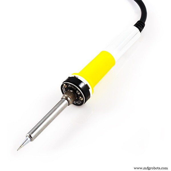
我将在 bare-bones 项目中使用以下部分 功能:
- 英飞凌的 Sensor Hub Nano
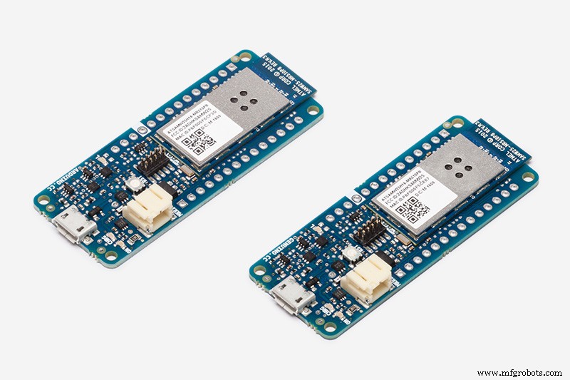
- Arduino MKR1000
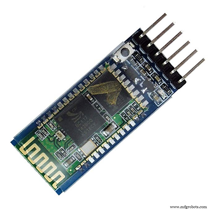
- HC-05 蓝牙模块
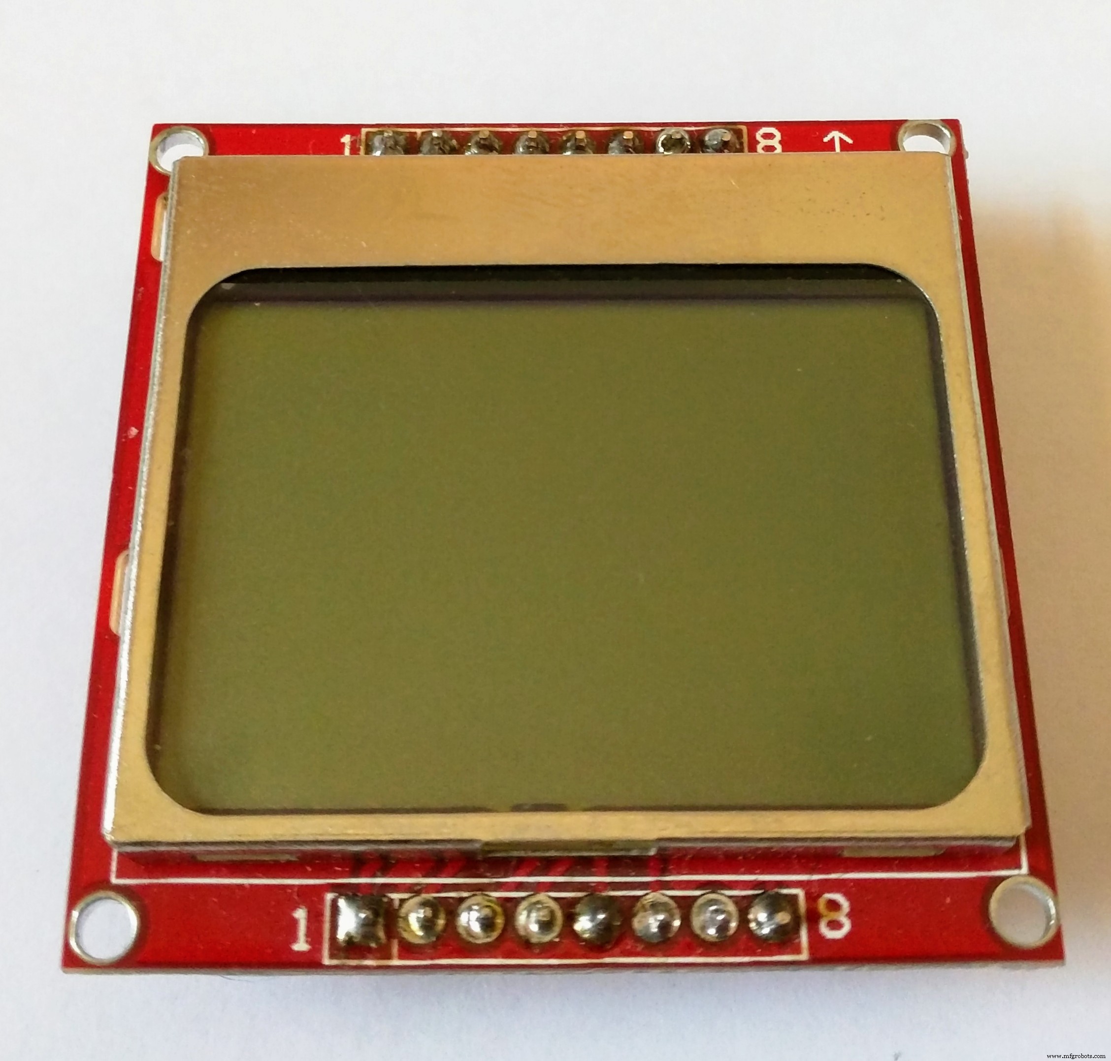
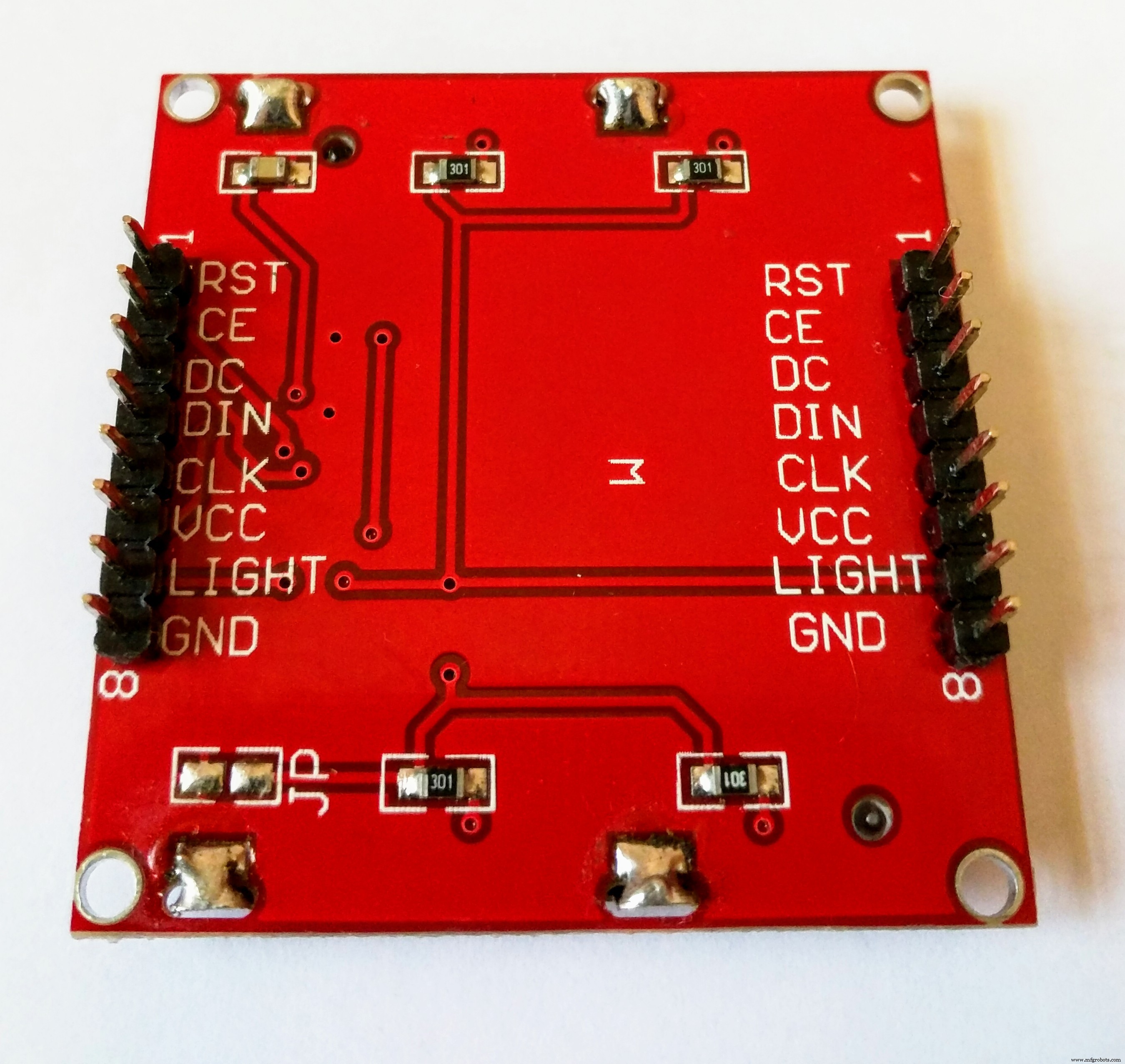
- 诺基亚 5110 显示屏

当您阅读“个性化阿尔茨海默氏症助手”部分时,您就会明白我所说的“基本项目”是什么意思。
工作原理
在本节中,我将简要介绍手表的工作原理,并概述我们必须执行的步骤才能使其工作。
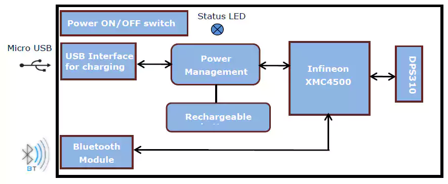
Infineon 的 Sensor Hub Nano 评估板有一个 DPS310 气压传感器,它通过蓝牙通过评估板发送数据。压力、高度和温度值可以在 Infineon 的 Android 应用程序(在此处下载)以及 SES2G 评估软件中查看。用户还可以根据自己的需求,使用英飞凌提供的库为 Android 构建应用程序。
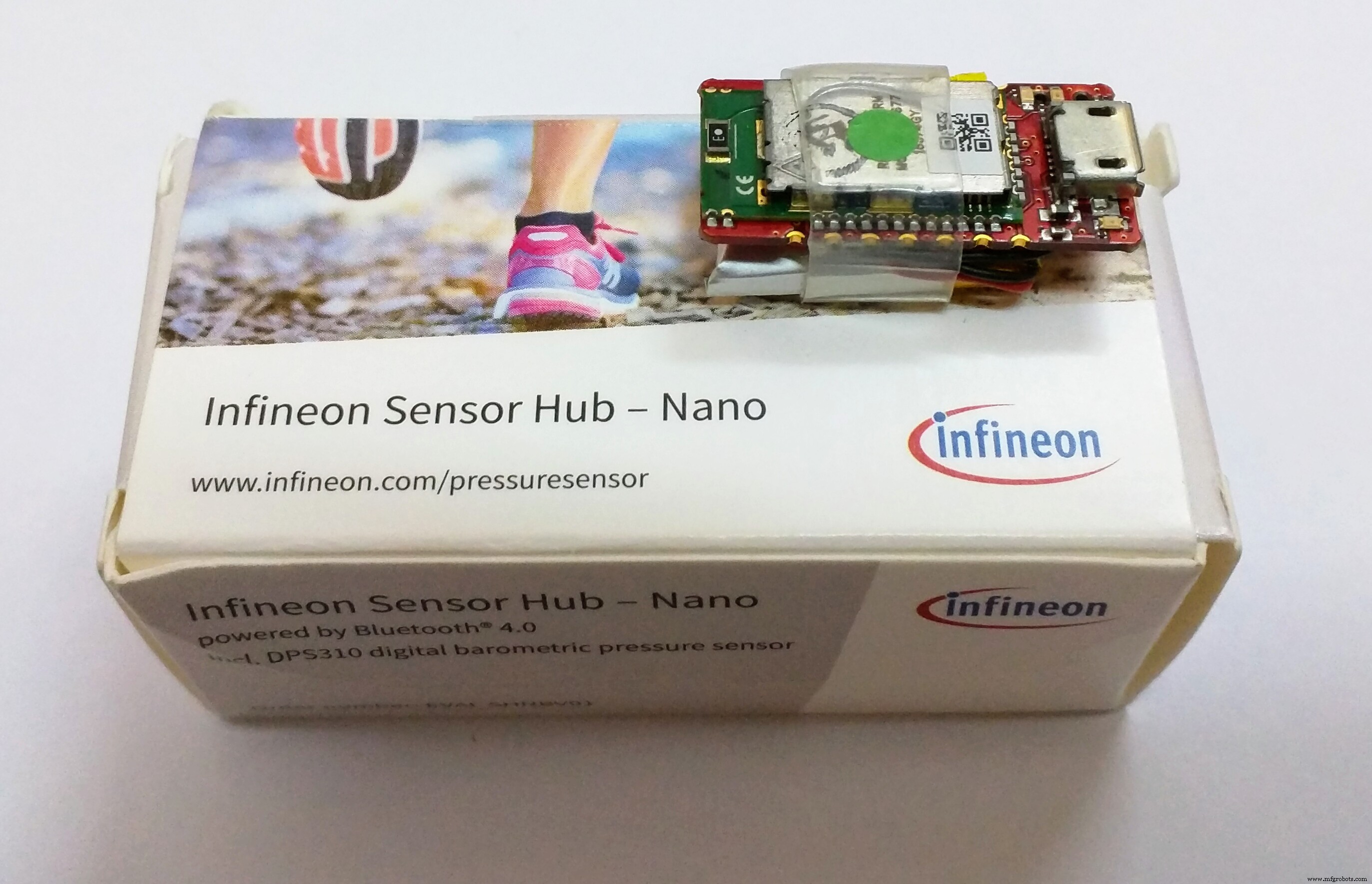
您可以在此处找到有关 Sensor Hub Nano 的更多信息。
但是,我希望阿尔茨海默氏症助手能够在没有 Android 手机的情况下工作。它应该是一种可自行工作的可穿戴设备,并且能够连接到智能手机以查看传感器数据。因此,我决定使用 Arduino MKR1000 板,因为它的外形小巧且具有 WiFi 功能,并通过某种方法将其连接到 Sensor Hub Nano。
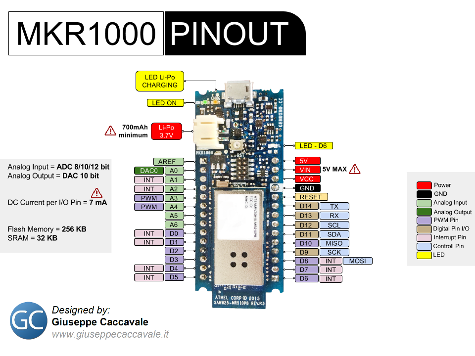
这是 Arduino MKR1000 的引出线,您会发现它很方便:
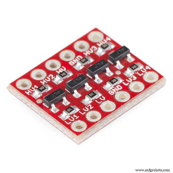
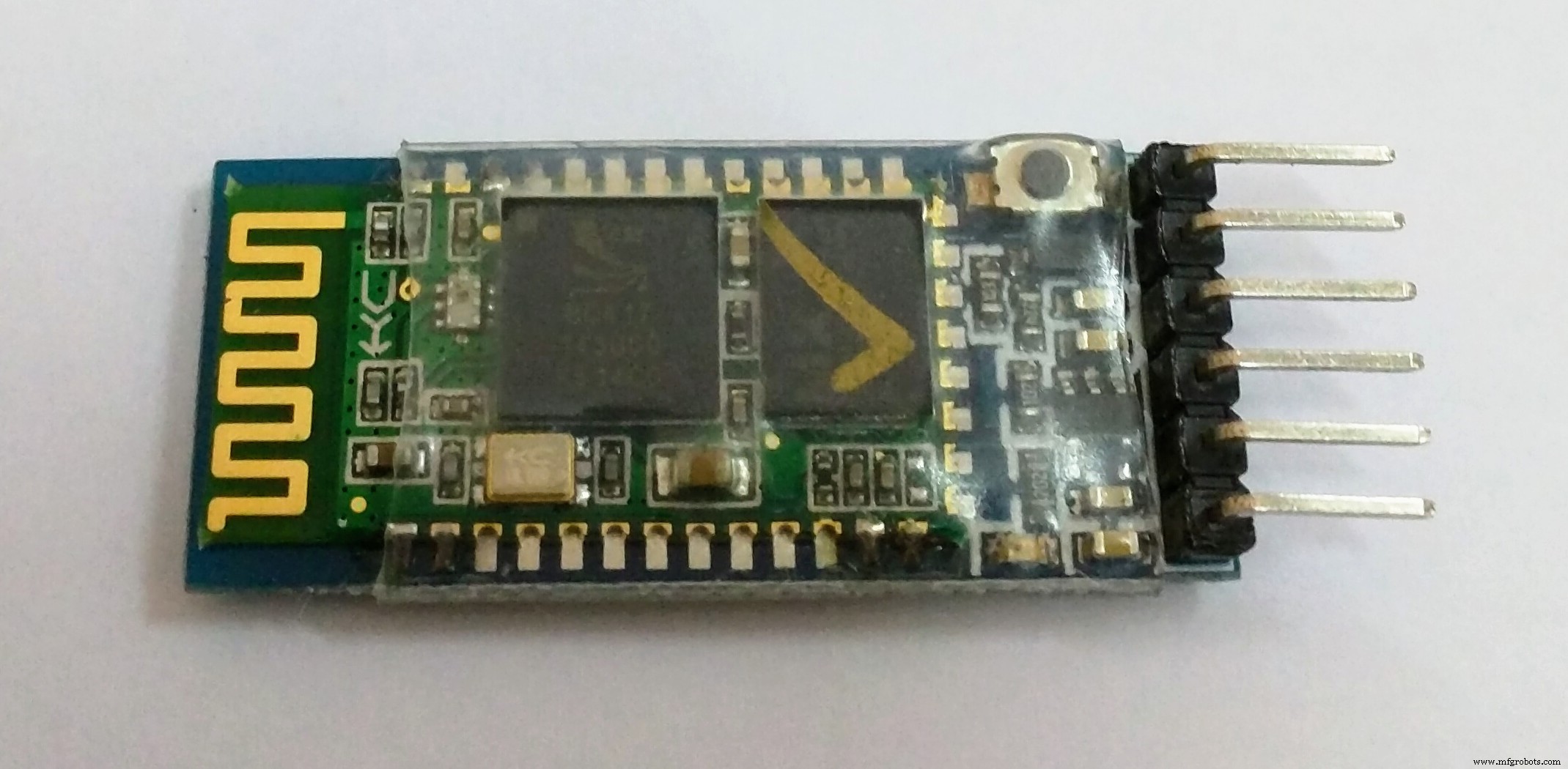
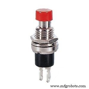
我有一个 HC-05 蓝牙模块,所以我不得不用它来连接 Arduino MKR1000 和 Sensor Hub Nano。但首先,我们需要将 HC-05 正确连接到 Arduino 的硬件 Tx 和 Rx 引脚,同时考虑到逻辑电平。我的蓝牙模块工作在 3.3v,与 MKR1000 相同,因此不需要任何电压电平转换器。但如果您的蓝牙模块工作在 5v 电平,则可能需要使用类似于所示的电平转换器。
匹配电压电平后,我们需要将HC-05与Sensor Hub Nano配对以开始它们之间的数据通信,并找到一种简单的方法让Sensor Hub Nano每次进入HC的蓝牙范围时自动配对-05.
为此,我考虑将 HC-05 配置为蓝牙“主”设备,并仅将其与特定的 MAC 地址配对;传感器集线器纳米。因此,在这样配置之后,一旦您打开 HC-05,它就会搜索具有特定 MAC 地址(Sensor Hub Nano 的 MAC 地址)的设备,并自动与之配对,由用户发送和接收数据。
这是使用 HC-05 的 AT 模式命令完成的,并在“配置蓝牙模块”部分进行了介绍。
注意:我附上了网上找到的一份文件,里面列出了HC-05支持的所有AT命令,请根据需要使用。
一旦配对并正确连接,向 Sensor Hub Nano 发送命令就像一个蓝牙终端。您可以使用我上面指定的命令,只需通过 HC-05 连接的硬件串行端口将它们打印为字符串即可。例如,这是您将发送以启动传感器数据流的命令:
$start_sensor id=1 //启动传感器数据流 这是我知道的命令列表:
$hello id=//Hello
$info id=//Info
$sinfo id=1 //传感器信息
$set_mode sid=1;md=mode;val=bg //低能耗
$set_mode sid=1;md=prs_osr;val=16 //标准模式
$set_mode sid=1;md=prs_mr;val=32 //高精度
$start_sensor id=1 //开始
$stop id=//停止
来自 Sensor Hub Nano 的传感器数据采用以下格式:
$1,t,36.9299,1154206 //温度
$1,p,997.6813,1154206 //压力
$1,a,130.4305,1154206 //海拔
注意:我想参考 Peter Smith 的 博文, 帮助我开始使用蓝牙与 Sensor Hub Nano 通信。
一旦我们能够从模块开始数据流,我们就需要一种方法来解析它的数据。我必须承认,这是项目中最艰难的部分;一旦您发送了启动数据流的命令,Sensor Hub Nano 就会发送一个数据流,让接收数据的设备从中解析任何有意义的信息。因此,在尝试了许多不同复杂度的方法后(我不会在这里介绍),这是我想出的最简单、最有效的方法,用于解析来自 Sensor Hub Nano 的数据。
void getSensorValues() {
 //通过Serial1端口从Sensor Hub Nano检索传感器值
 StringjunkVal;
 if (Serial1.available()) {
junkVal =Serial1.readStringUntil('\n');
junkVal =Serial1.readStringUntil('t');
 t =Serial1.parseFloat();
junkVal =Serial1.readStringUntil('p');
 p =Serial1.parseFloat();
junkVal =Serial1.readStringUntil('a');
 a =Serial1.parseFloat();
junkVal =Serial1.readStringUntil('\n');
 }
}
显示器也将连接到 Arduino 以与用户交互,并显示任何消息,或显示时间或来自传感器的数据(更多信息请阅读)。
一旦您在 Arduino MKR1000 中获得数据,由于其无线连接,您可以将数据发送到许多不同的物联网平台,例如 Cayenne 或 Blynk。

为此我决定使用 Cayenne,因为它漂亮的界面和简单的设置给我留下了深刻的印象。但是,遗憾的是,它在 MKR1000 WiFi 连接上存在一些错误,导致我们无法选择引脚。我应该提到 Cayenne 那边的人非常有帮助,但问题仍然没有解决。因此,我最终决定使用 Blynk,但它们的用法非常相似,因此只需更改几行 Arduino 代码,如果您想测试一下或一旦出现问题,您可以从 Blynk 切换到 Cayenne解决。两者或多或少具有相同的功能,因此这只是您自己的喜好。但是 Cayenne 的唯一优势是您也可以在 PC 上访问它,而 Blynk 仅适用于智能手机。
现在,我们已经从 Sensor Hub Nano 接收到数据,将其输入 Arduino,并将其传输到 IoT 平台(从现在开始我会说 Blynk),因此,现在您只需要根据根据您自己的需要,这将在另一部分进行处理(跌落和位置检测在那里讨论)。
注意:我已经尝试详细记录每一步,但是如果您不知道某些事情(例如将代码上传到您的 Arduino),最好去 Arduino 主页 ,先熟悉一段时间,然后在至少了解基础知识后再回来。
配置蓝牙模块
您需要做的第一件事是获取 Sensor Hub Nano 评估套件的 MAC 地址。有很多不同的方法可以做到这一点,但我会告诉你我是如何做到的。
将 Sensor Hub Nano 与您的智能手机配对:
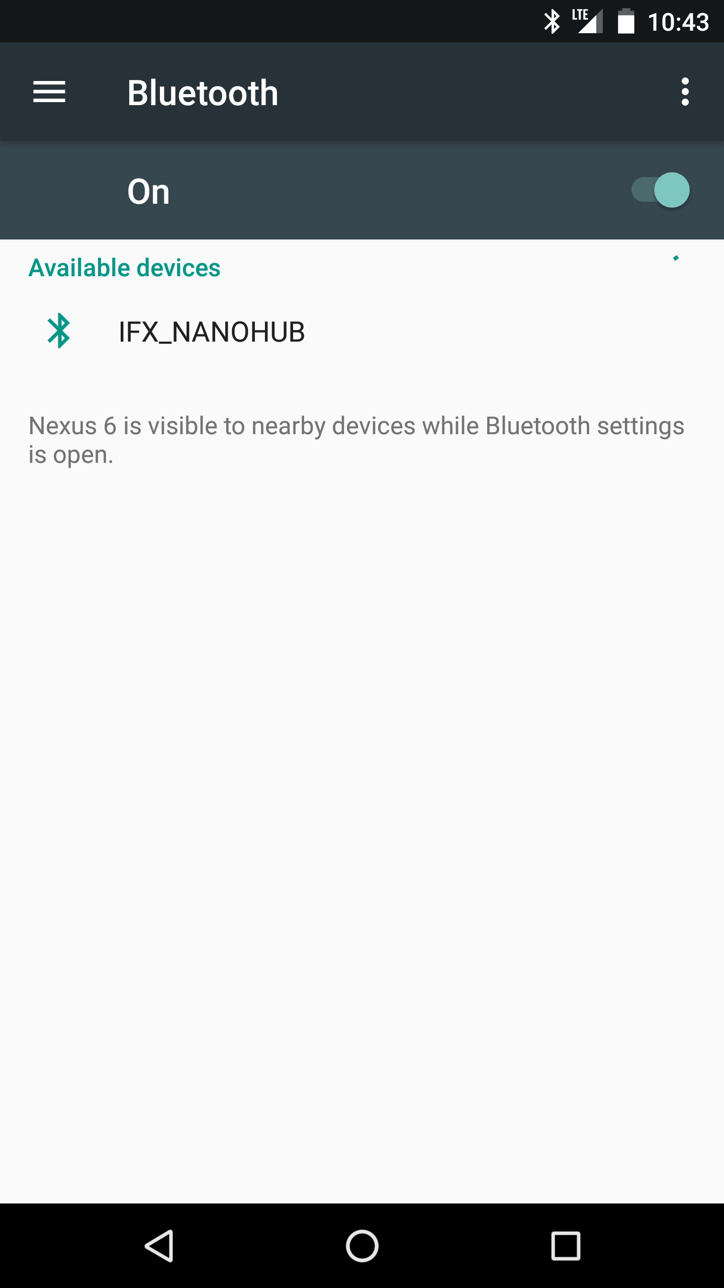

从这里下载 Infineon 的 Sensor Hub Nano 评估应用程序(适用于 Android)并打开您的 Sensor Hub Nano。打开应用程序,它将显示 Sensor Hub Nano 为“IFX_NANOHUB”,其下方是 MAC 地址。
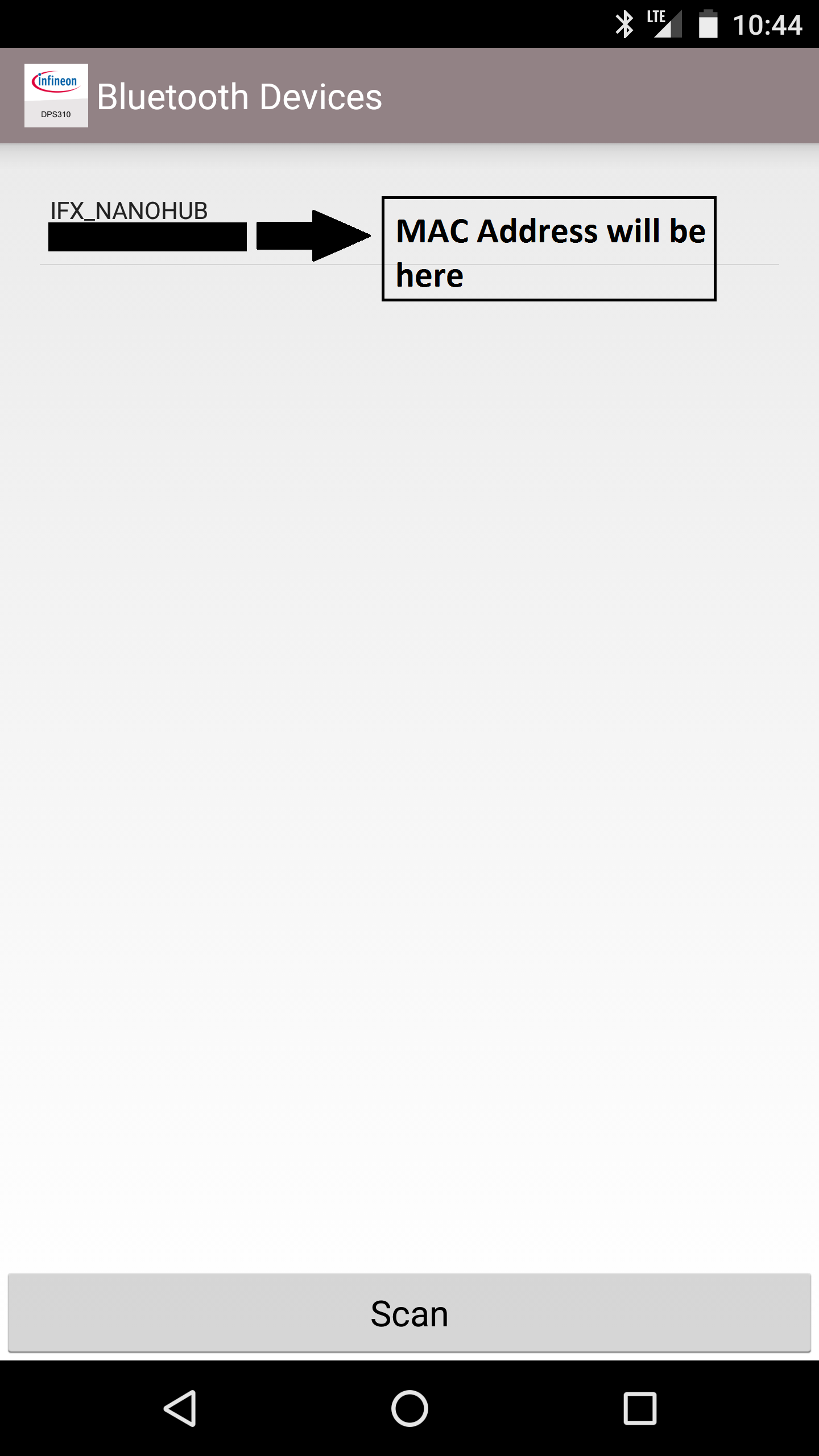
请记下这一点,因为您稍后会需要它。
注意:如果您现在不使用 Sensor Hub Nano,最好将其与智能手机取消配对,因为如果您的手机在附近并开启蓝牙并且 Sensor Hub Nano 已配对,手机会自动与其连接.当您设置 HC-05 并尝试使其与 Nano Hub 配对时,它根本无法连接。
让 HC-05 进入 AT 模式:
AT模式允许我们配置HC-05蓝牙模块的设置;设置波特率或设置是否作为从设备或主设备连接等等。我们需要更改模块的一些设置,以使其能够从 Infineon 的 Sensor Hub Nano 成功检索数据。
首先,将“AT 命令”草图上传到 Arduino MKR1000。这将允许我们在 AT 模式下通过 Arduino MKR1000 向蓝牙模块发出命令。
// Martyn Currey 博客的原始草图:
// http://www.martyncurrey.com/arduino-with-hc-05-bluetooth-module-at-mode/
//
// 我修改的草图与 Arduino MKR1000 配合使用!
//
// 基本蓝牙草图
// 连接 HC-05 模块并使用串行监视器进行通信
//
// HC-05 默认首次通电时进入通信模式。
// 需要进入 AT 模式
// 恢复出厂设置后通信模式的默认波特率为 38400
char c =' ';
void setup() {
// 启动与主机的串口通信
Serial.begin(9600);
Serial.println("带有 HC-05 的 Arduino 已准备就绪");
// 使用 38400 开始与 HC-05 的通信
Serial1.begin(38400);
Serial.println("Serial1 从 38400 开始");
}
void loop() {
// 继续从 HC-05 读取数据并发送到 Arduino 串行监视器
if (Serial1.available())
{
c =Serial1.read();
Serial.write(c);
}
// 继续从 Arduino 串行监视器读取数据并发送到 HC-05
if (Serial.available())
{
c =Serial.read( );
// 将命令镜像回串行监视器
// 使执行命令变得容易
Serial.write(c);
Serial1.write(c);
}
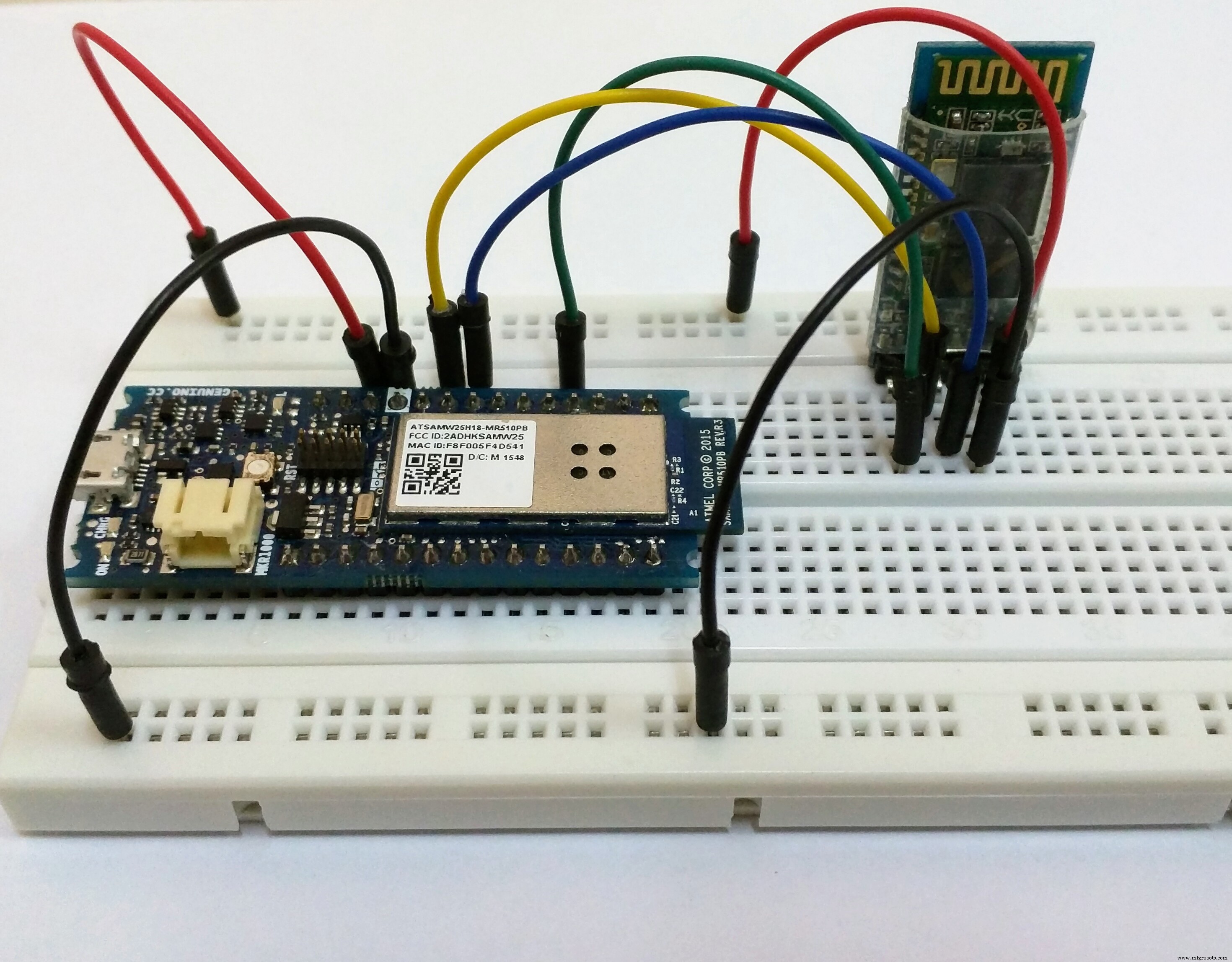
} 然后按照图仅将蓝牙模块连接到 Arduino MKR1000。
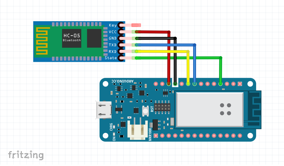
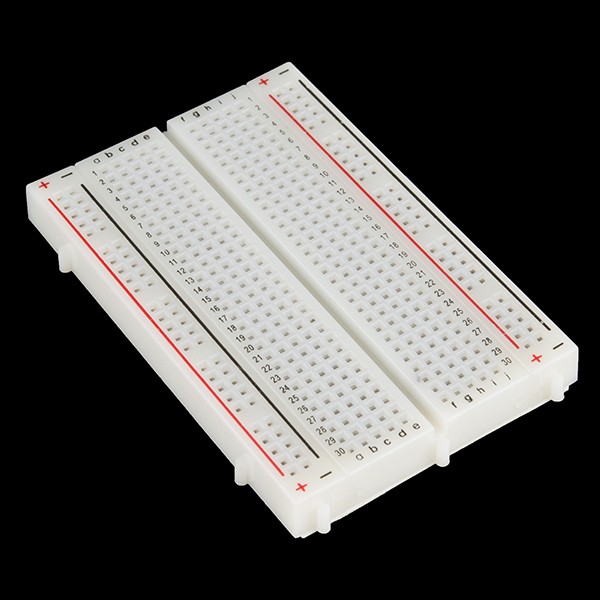
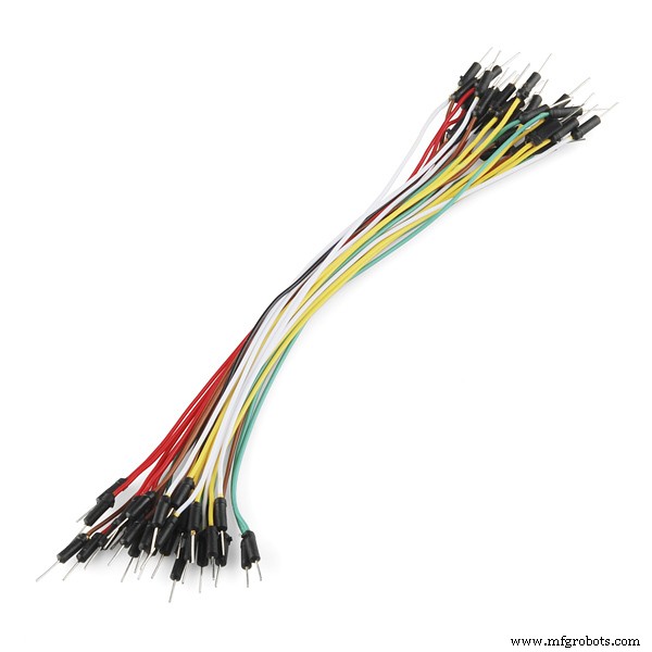
注意:最好先在面包板上接线,然后在正确设置后进行正确接线。
如果您尝试打开 Sensor Hub Nano 和 HC-05,您会看到它们此时不会自动连接。这就是你会看到的:
要更改 HC-05 设置,您需要让蓝牙模块处于 AT 模式。执行此操作的方法取决于您拥有的分线板,因此您可能必须以不同的方式进行。如果您的模块与我的模块不同,请访问 Martyn Currey 的博客,在这里您可以找到有关如何在 AT 模式下获取 HC-05 蓝牙模块的详细信息。如果您遇到困难,请在谷歌上搜索您的问题或发表评论,我会尽力提供帮助。
我的蓝牙模块有按钮开关,所以我必须执行以下步骤才能使其进入AT命令模式(不要忘记将AT命令代码上传到Arduino):
- 断开模块的电源。 (TX 和 RX 线仍然连接!)
- 按住模块上的按钮开关关闭
- 在按住按钮开关的同时接通电源
- 当 LED 亮起时,松开开关
展示如何在 AT 模式下获得 HC-05 的视频:
进入 AT 模式后,您会注意到 HC-05 上 LED 闪烁模式的显着差异。在通信模式下,LED 快速闪烁,大约每秒 5 次,而在 AT 模式下,LED 每隔几秒闪烁一次。
设置 HC-05 模块:
打开串口监视器,设置波特率为9600,选择“Both NL &CR”。
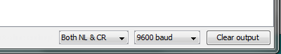
注意:您需要将其设置为换行符和回车符,否则 AT 命令不起作用。
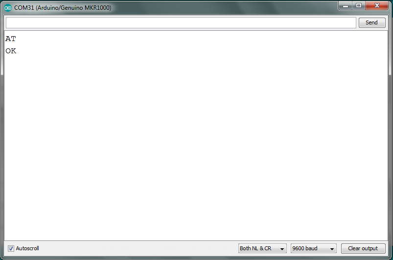
在串行监视器中键入“AT”,您应该会收到“OK”。如果你这样做了,那么你可以继续前进并像我一样发出命令。
基本上,我们需要在 AT 模式下更改这些设置:
- 删除所有当前配对的设备
- 让它只连接到指定的蓝牙 MAC 地址
- 将蓝牙连接模式设置为“主”
- 指定我们需要它连接的 MAC 地址
- 设置波特率为115200,停止位为2位,偶校验
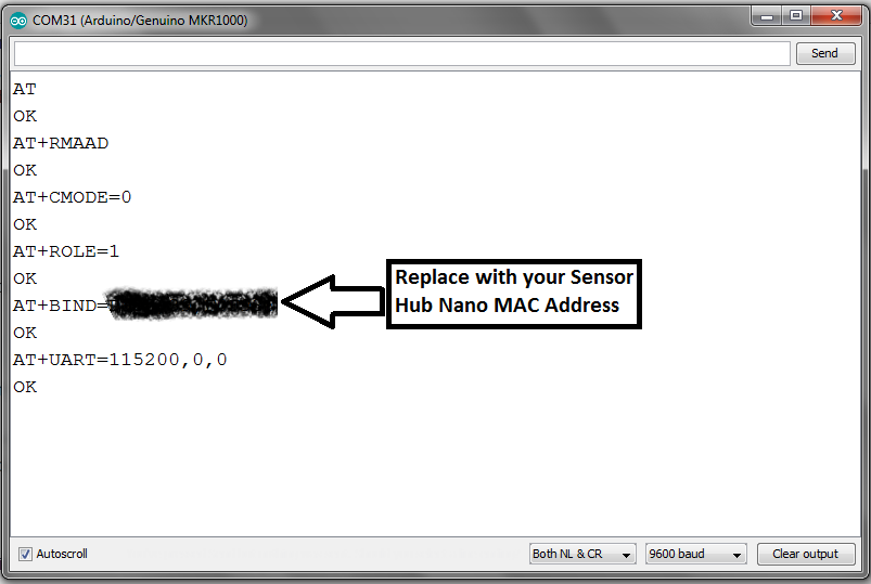
给出了上述说明,以便您即使有另一个蓝牙模块也可以通过参考命令和它们的作用来使用它们。但现在我将列出我给 HC-05 与 Sensor Hub Nano 配对的命令。
- AT+RMAAD
- AT+CMODE=0
- AT+ROLE=1
- AT+BIND=1234,56,abcdef(替换为 Sensor Hub Nano 的 MAC 地址)
- AT+UART=115200,0,0
这是我的 AT 命令的日志,供您参考:
您现在应该拔下 Arduino 以关闭蓝牙模块。这将使其恢复通信模式。
注意:如果您在 HC-05 设置中搞砸了任何事情,最好将模块重置为默认设置并使用以下命令从头开始:AT+ORGL
测试连接:
现在,您需要测试最后一步是否成功;你可以通过打开 Sensor Hub Nano 来做到这一点。蓝色 LED 会非常缓慢地闪烁,每隔几秒钟闪烁一次。然后,将您的 Arduino 插入您的 PC,并注意 HC-05 和 Sesnor Hub Nano 上 LED 闪烁的变化。
看看现在的闪烁并与之前的闪烁进行比较:
有一个明显的区别,你应该知道这两个模块是相连的。您现在可以转到下一部分,即连接项目并对其进行测试。
注意:如果您之前已将智能手机与 Sensor Hub Nano 配对,则可能需要取消配对,否则会导致连接问题。它一次只能连接到一台设备。
测试基本项目
通过 LED 闪烁模式确认 HC-05 和 Sensor Hub Nano 之间的连接正确后,继续在智能手机中设置 Blynk 应用程序。
设置 Blynk 应用程序:
从这里下载适用于您的 iOS 或 Android 设备的 Blynk 应用程序(如果您还没有),然后通过 Blynk 应用程序扫描二维码。它将自动复制此时所需的基本小部件。

您将看到类似的屏幕:
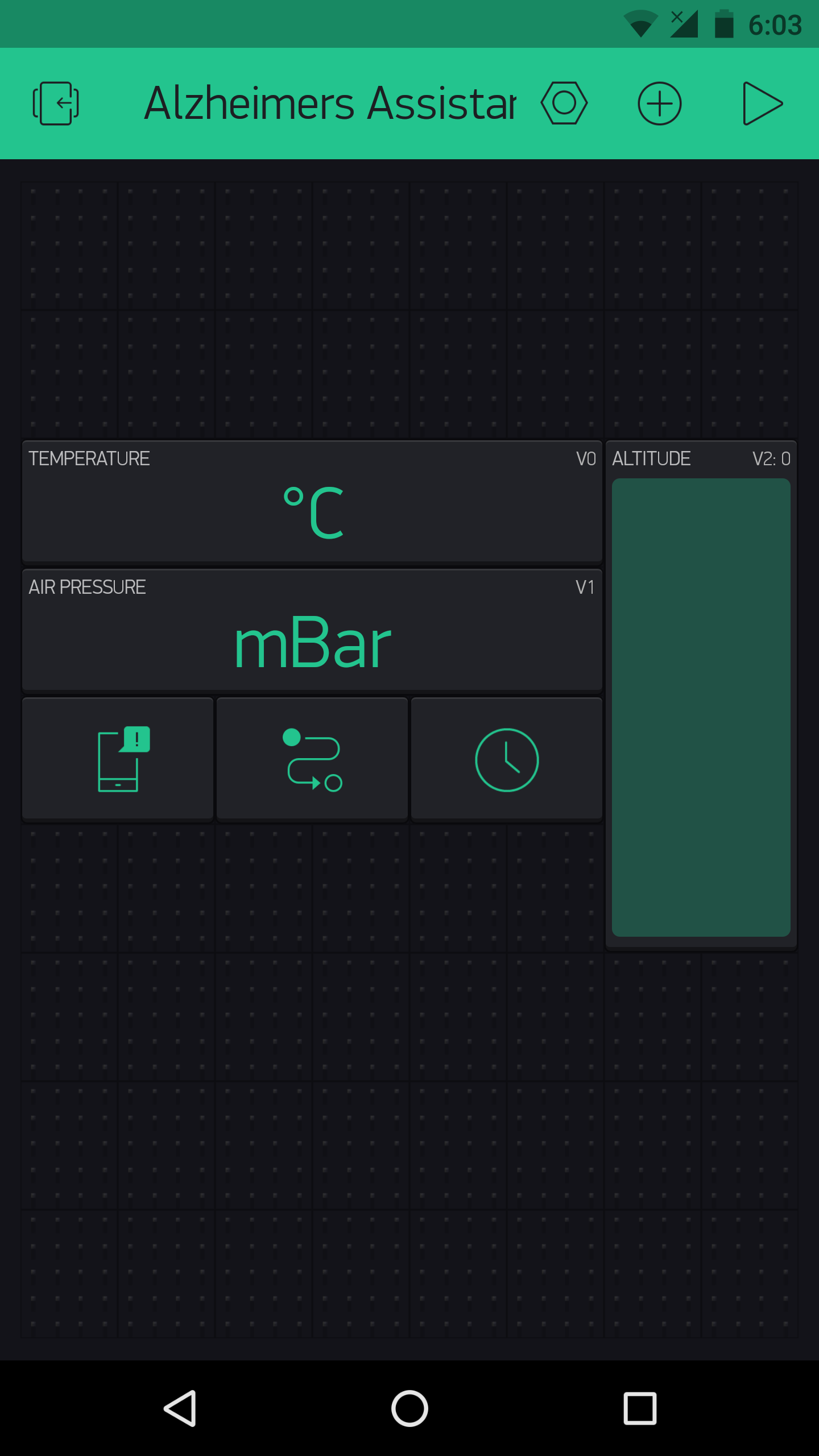
此时不要在此处进行任何更改,请继续阅读。
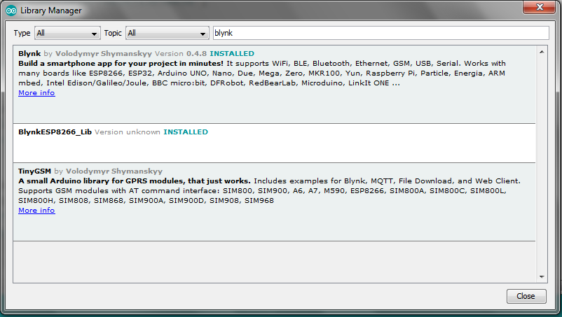
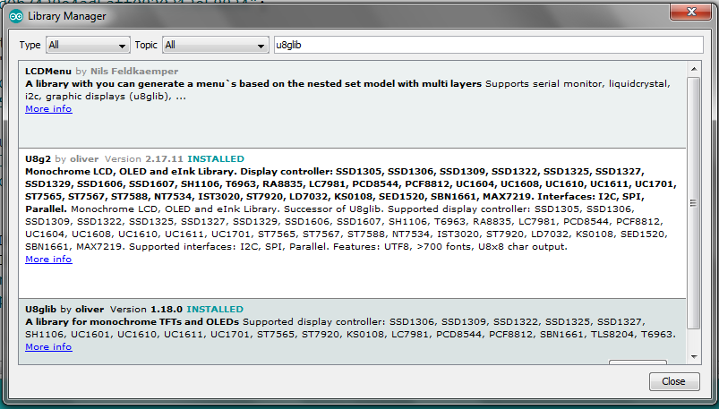
安装所需的库:
您需要为 Arduino IDE 安装两个不同的库,以使代码能够无误地编译。它们是:
- 布林克 , 将其连接到您的智能手机
- u8g2lib , 用于显示
有两种方法可以安装所需的库。第一种是通过较新版本的 Arduino IDE 中提供的“库管理器”,第二种是手动安装。此处详细介绍了这两种方法,因此请查看链接,因为我不会详细介绍。
上传代码和测试:
安装库后,下载附加的代码并对其进行一些更改。您需要添加来自 Blynk 的身份验证代码(在 Blynk 中创建新项目时会通过电子邮件发送给您),以及您的 WiFi SSID 和密码。完成后,将代码上传到 MKR1000。
上传代码后,按照原理图接线。

然后在您的智能手机中打开 Blynk 应用程序,打开阿尔茨海默氏症助手项目并按下播放按钮。插入 MKR1000(将 HC-05 和显示器连接起来),您应该会在显示器上看到标志,Alzheimer's Assistant。它会停留片刻,然后您可以看到消息“Waiting for Sensor Hub Nano ”。打开 Sensor Hub Nano 上的小开关,确保您在 HC-05 模块的蓝牙范围内。它应该说“连接到 Infineon 的 Sensor Hub Nano ",几秒钟后,您应该会在智能手机上看到压力温度和高度值。
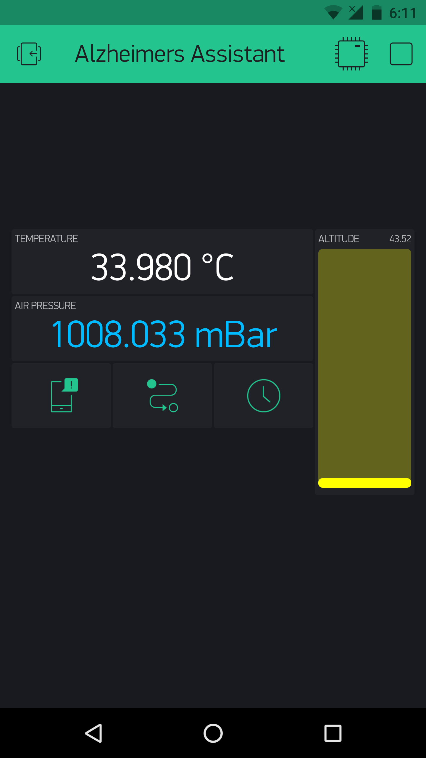
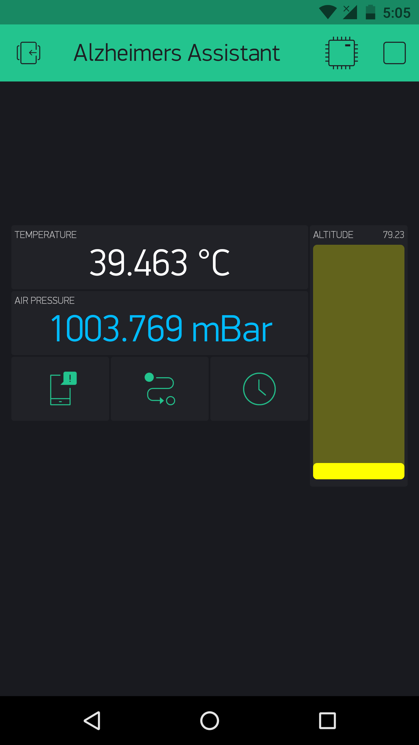
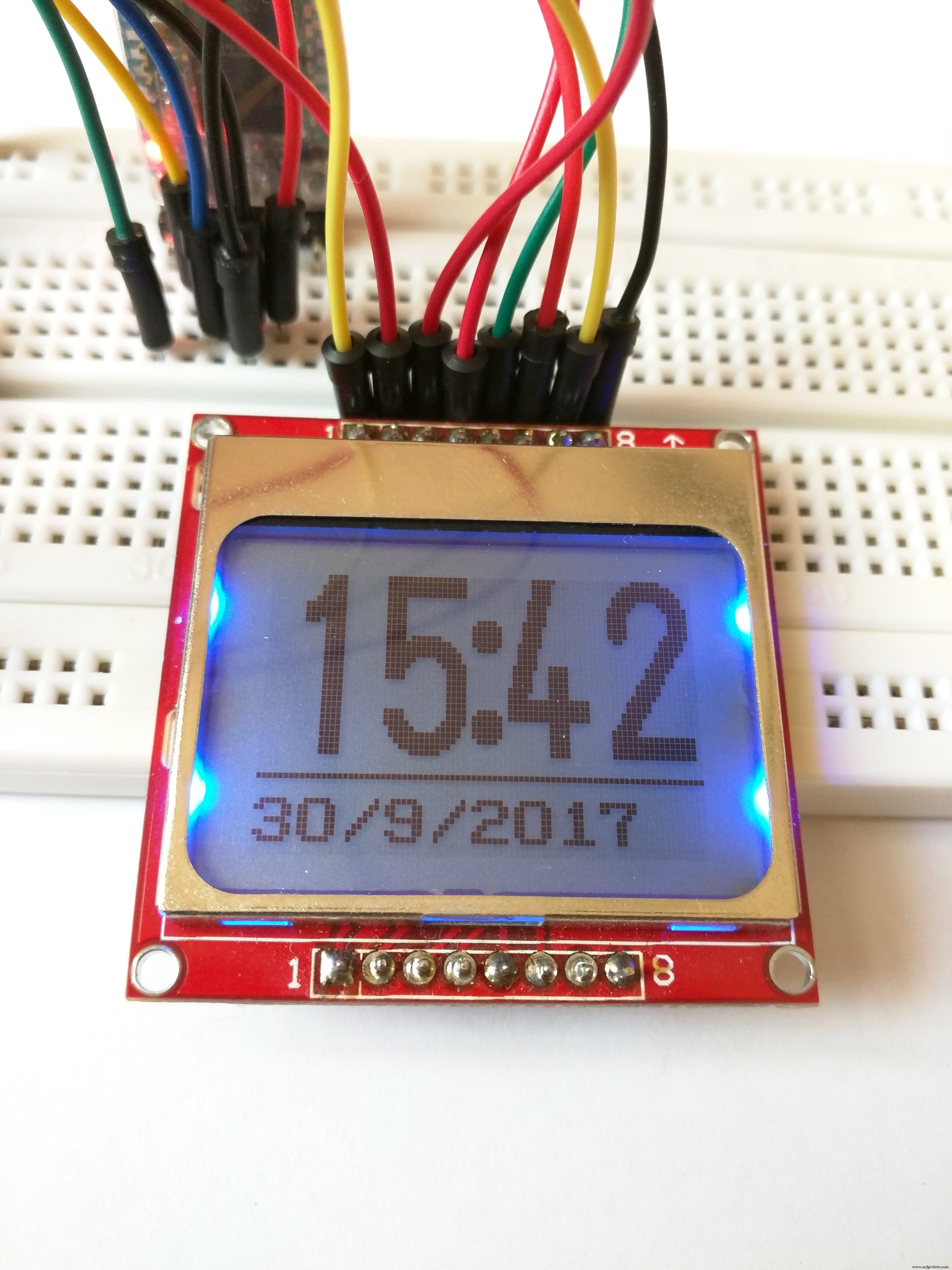
几秒钟后,您还将看到 24 小时格式的时间以及日期,并与互联网同步。
这是一个测试它的视频:
如果是这样,那么恭喜您,您已经完成了设置的艰难部分,现在可以根据患者的喜好为其个性化设置了。
个性化阿尔茨海默氏症助手
到目前为止,我们的设置以简洁优雅的设置从英飞凌 DPS310 检索传感器数据,但要从中获得有用的东西,我们必须根据个人要求和偏好配置设置。因此,在本节中,我将讨论代码以及如何根据每个用户的喜好修改阿尔茨海默氏症助手使其工作。我会给出每个“功能”的代码片段,你可以简单地将它添加到主代码中,稍作改动。
注意:当您查看我为“裸机项目”附加的代码时,您会看到它使用了 BlynkTimer 中包装的函数。如果您想进行任何自定义,我将是一个好主意,因为它可以在指定的时间间隔执行任务,并且还可以防止硬件向 Blynk 发送大量请求时发生的 Blynk 洪水错误。此外,从所有功能都存在但不包含在主代码中的意义上说,代码是“简单的”;用户必须根据需要编辑主代码,并且可能需要调整每个函数运行的时间间隔。
DPS310:-
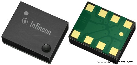
Infineon 的 DPS310 是一款低成本数字气压传感器,它以非常小的外形尺寸提供非常高的精度。正因为如此,在这样的项目中使用它是完美的,这些值可以用来检测老年患者的跌倒,或者患者确切在哪个房间。
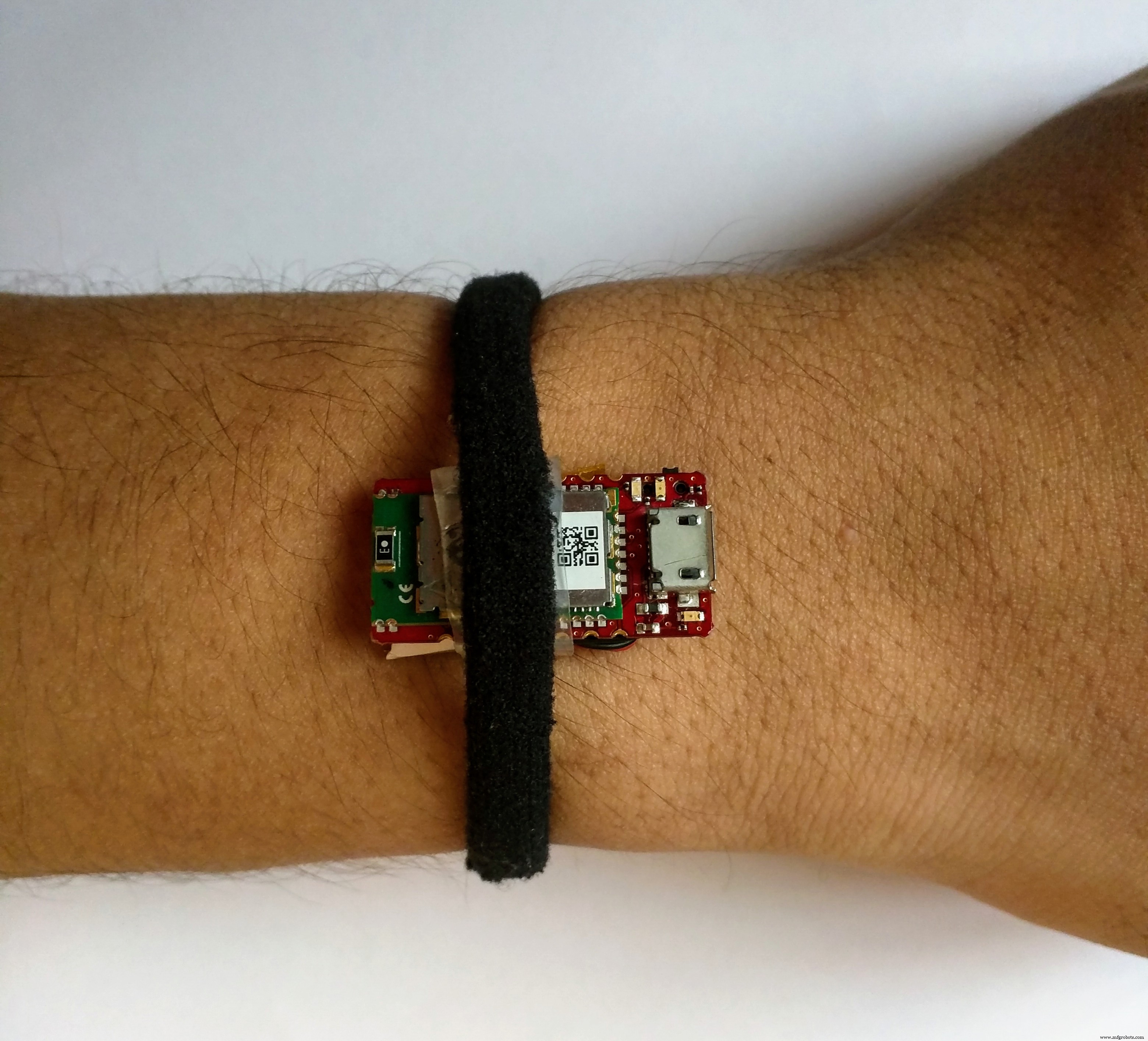
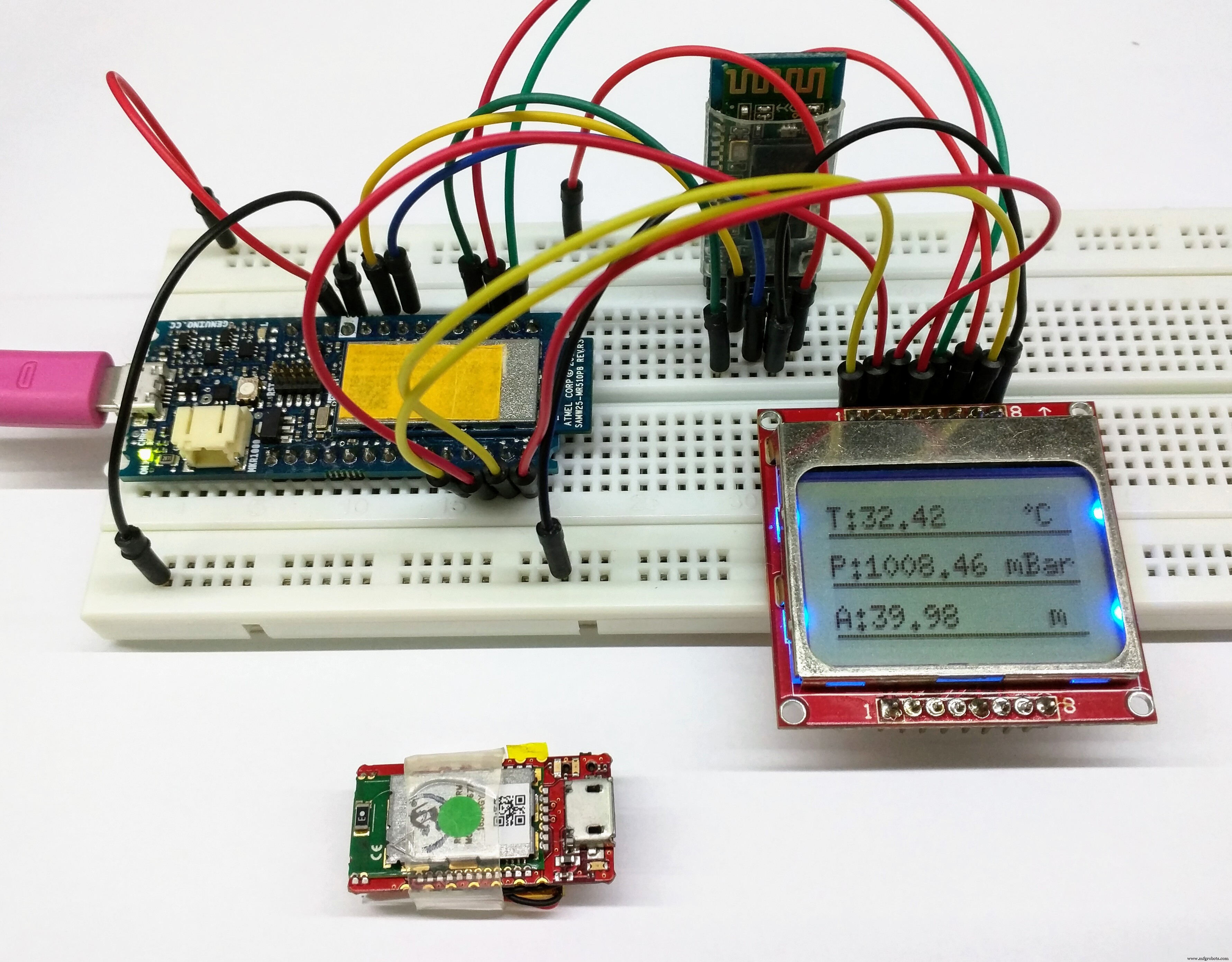
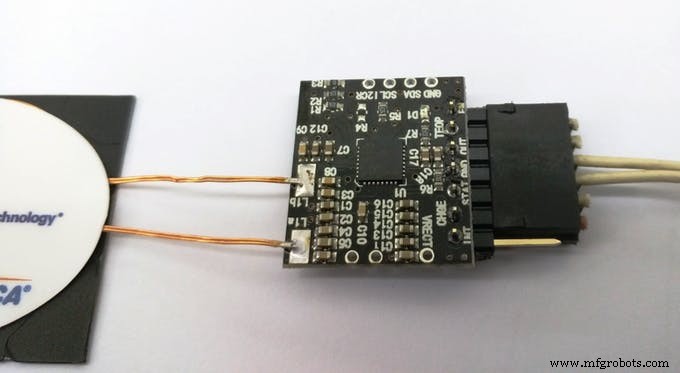
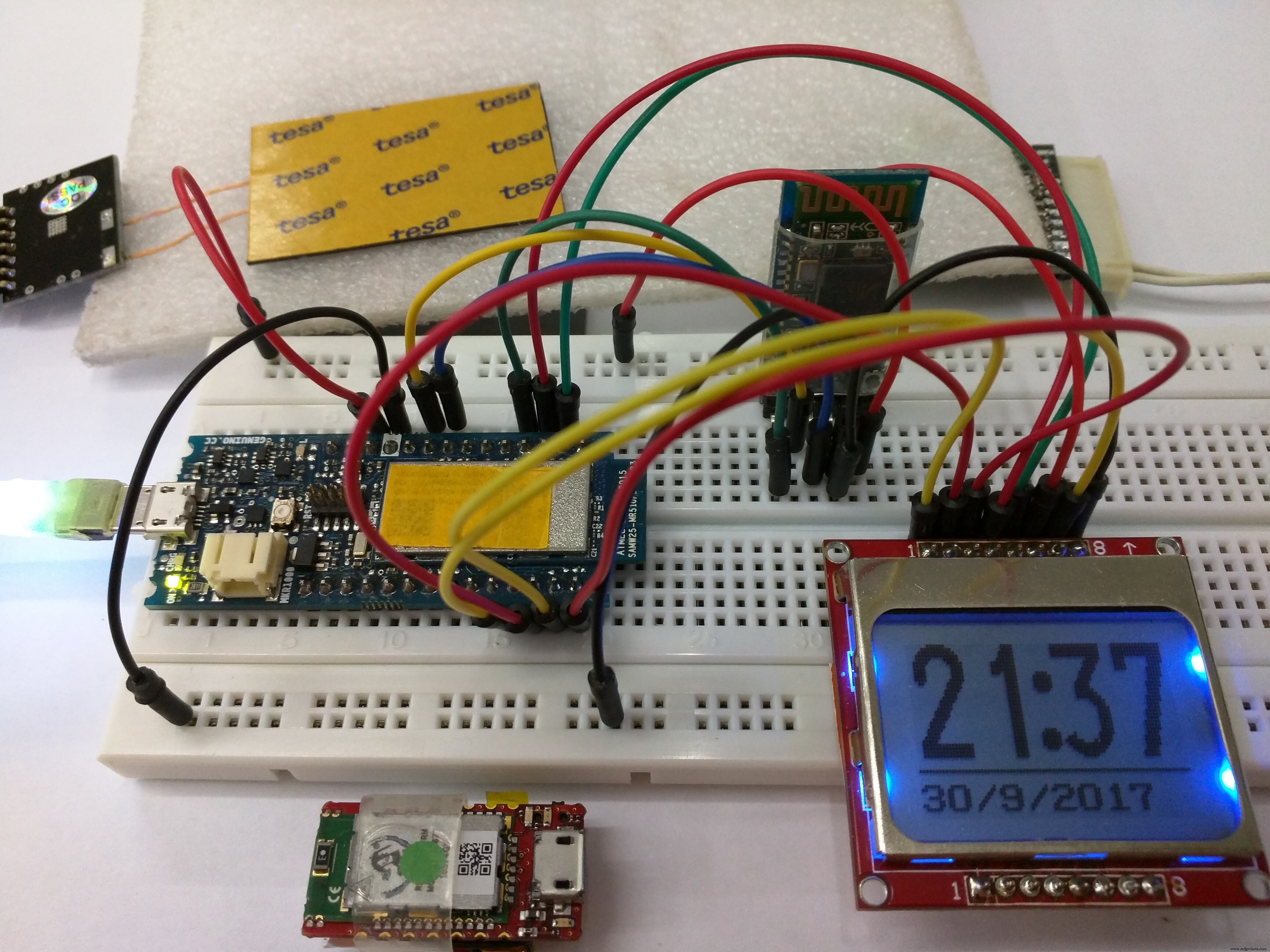
注意:我还没有制作智能手表外壳,所以我正在使用我手上的 Sensor Hub Nano,通过蓝牙与 Arduino 连接,如下图所示:
跌倒检测: 要检测跌倒,我们需要给出跌倒值(指定时间内两次读数之间的气压差),并设置间隙。例如,如果两个连续值之间的高度变化(比如一秒的时间)在下降值 ± 间隙值之间,则将检测到下降。
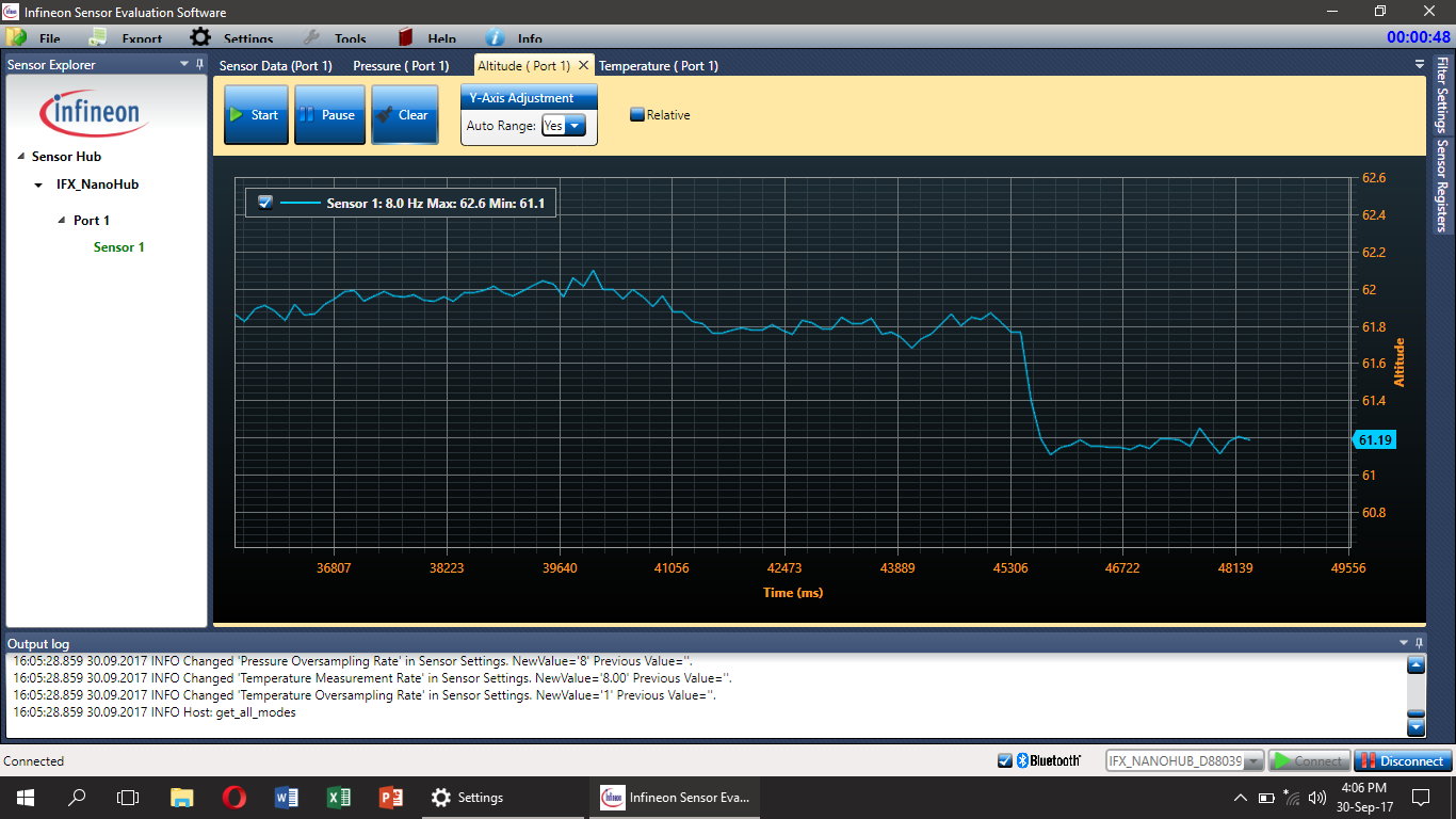
我做了几次测试,发现下降值应该是0.7,间隙值应该是±0.2,但它们可能不适用于所有情况。这是由于一个简单易懂的原因,当一个人跌倒时,它可能以多种不同的方式发生。因此,需要使用辅助传感器(可能是加速度计)来提高跌倒检测系统的准确性,这将被添加到未来的工作中。但是总是有可能有其他更准确的算法来检测跌倒,我很乐意听到它们;如果您对此有任何想法,请随时发表评论。
一段演示跌倒检测的视频:
检测患者在哪里: 这类似于跌倒检测算法。例如,如果您需要知道患者在哪个楼层,您可以获取当前高度值并将其从先前的值中减去。然后将差异与预定义的值进行比较。这将指示患者在哪个楼层。
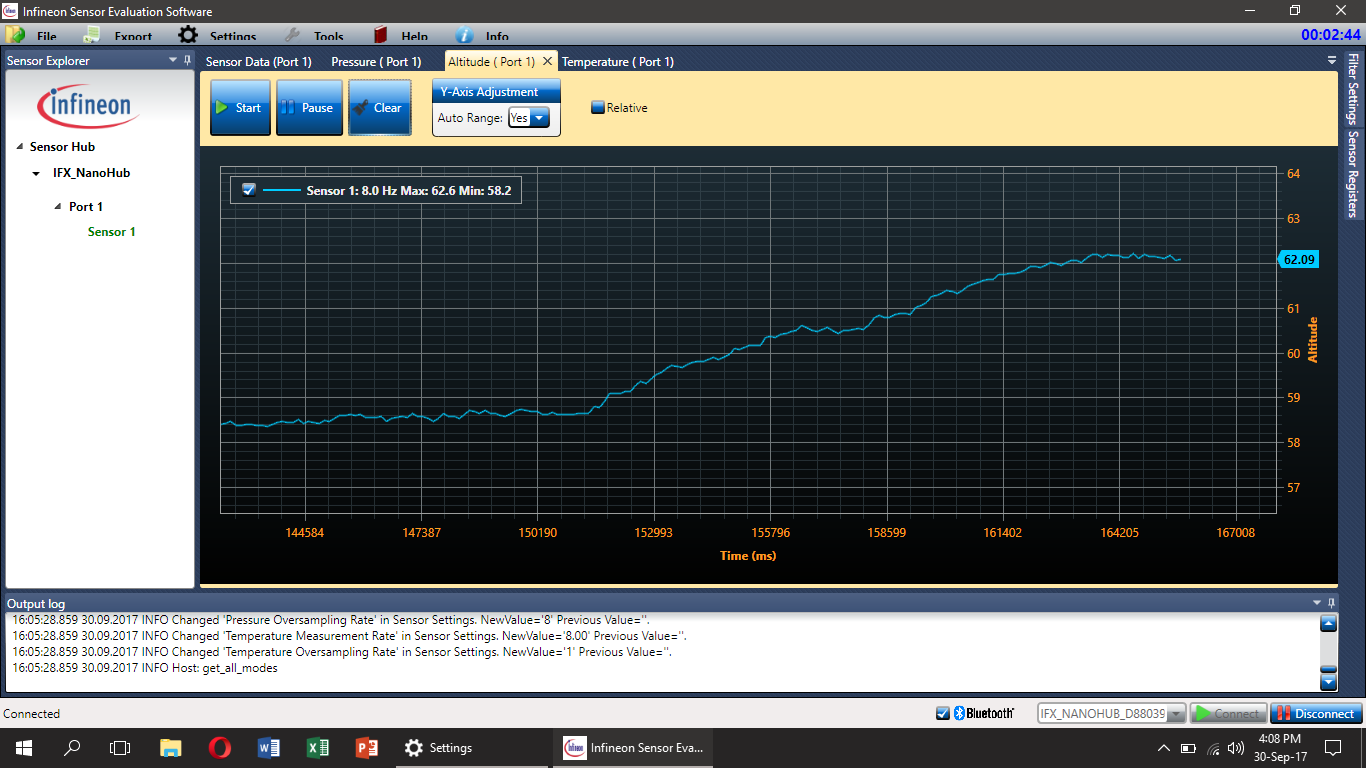
只需使用简单的 if 和 else 逻辑来确定患者所在的楼层(海拔值已经存在于主代码中)。这可以使用 Blynk 中的 LED 小部件来指示。
注意:我没有在主代码中包含位置检测,但用户可以根据需要添加它,只是不要忘记将其用作 Blynk 计时器功能。
同样的技术也可以用来检测一个人在哪个房间。在这种情况下,需要一个辅助传感器,例如运动传感器,否则可能会出现很多误触发。
温度: DPS310 还显示温度值,我们可以使用它来提醒我们有关患者可能发生的任何事故,例如火灾。如果温度升高到特定值,比如说 45℃,它会提醒管理员。
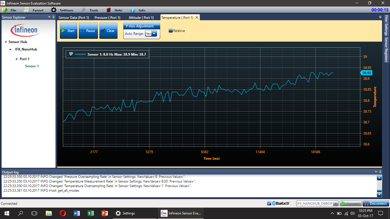
但是因为 DPS310 传感器没有直接连接到皮肤(至少在这个用例中),我们得到的不是体温,但更准确地说它是 Sensor Hub Nano 的温度。
代码非常简单(在主循环中的任何地方使用),可能是这样的:
if (t> maxTemp) {
 //如果温度高于最大值,做你想做的
}
else {
 //做你想做的如果温度低于最大值
}
注意:以上所有图表均使用英飞凌提供的 SESG2 评估软件创建。
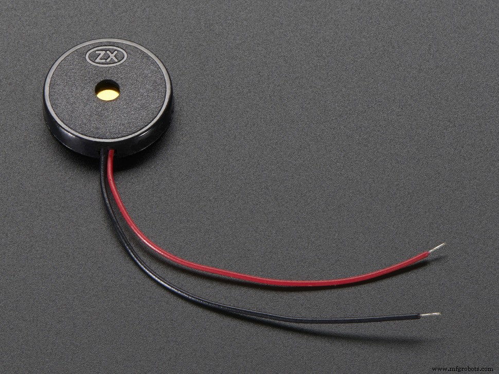
一个蜂鸣器和一个开关:-
我之前没有提到过这一点,但是系统中还应该有一个蜂鸣器和一个开关,它们也会很有帮助。例如,可以使用蜂鸣器来吸引患者的注意力,例如该吃药的时间,而开关可以用作安全装置。
因为我们将使用 Blynk,按钮开关可以设置为按下时,通知会出现在看守人的手机上,或者它会打电话或发送短信(这可以使用 IFTTT 完成,稍后会给出) )。这可能是执行此操作的代码片段:
void emailOnButtonPress()
{
 // *** 警告:您每 15 秒只能发送一封电子邮件! ***
 // 当您按下按钮时,让我们发送电子邮件
 // 连接到 Arduino 上的数字引脚 2
 int isButtonPressed =!digitalRead(2); // 反转状态,因为按钮是 "Active LOW"
 if (isButtonPressed) // 您可以编写任何条件来触发电子邮件发送
 {
 Serial.println("Button is press ."); // 这可以在串行监视器中看到
 Blynk.email("[email protected]", "Subject:Button Logger", "You just push the button...");
 // 或者,如果您想使用应用程序中指定的电子邮件(如应用程序导出):
 //Blynk.email("Subject:Button Logger", "您刚刚按下了按钮。 ..");
 }
}
它取自 Blynk 示例代码,并使用中断来检查按钮。患者可以使用它在任何紧急情况下提醒看护人,例如跌倒检测算法未检测到的跌倒。您可以在此处获取完整的示例代码,一旦按下按钮,它就会发送一封电子邮件。
蜂鸣器可用于产生音调(使用 Arduino 音调()命令 - 此处有更多信息),以提醒患者进行诸如药物治疗或锻炼之类的任务。
显示:-
用户实际查看的项目的主要部分是显示。诺基亚 5110 显示器很常见,易于设置且价格便宜,但它们并不那么华丽,尤其是在这样的系统中使用时。具有更高分辨率的 OLED 显示器将是它的一个很好的替代品,您可以轻松修改代码以使用它,因为我使用了 u8g2 库(此处为 github)。从此处选择任何显示器型号,并将其添加到草图的开头(当然,删除诺基亚 5110 系列!)。 You will need to wire it up according to what it is in the code and you’re ready to go. You can also use bitmap images with a higher resolution display. You can also change the font for the text on the display, select fonts from the huge list here and edit the name of the font in the code.
Note:You may have to change the pixel positions for the text in the code if you use a display with a higher resolution.
That was just a brief description of the library used to get the display working. But, now I will tell you how to edit the code to get Alzheimer's Assistant to show the time or the Sensor Hub Nano data (temperature, Altitude and pressure).
Displaying time: To display the time, you could simply use an RTC (or time keeping module) but as we're connected to the Internet, it would be much more easier to use the Internet to sync the time. And as we're using Blynk that would make it even more simpler. You just need the RTC widget in your project. Now with a few lines of code, you can automatically retrieve the time from the Blynk server (Make sure to set your timezone from the Blynk widget). The main code is set to display the time by default (not the sensor values, discussed next)
Note:The time displayed on the screen could go up or down a minute, as it is synced from the internet, but despite that, I have tested it for a long time and have found it to be very accurate (just a difference of a few seconds).
Displaying the Sensor Hub Nano data: We could just as well display data from the Sensor Hub Nano in the display. Not that it would benefit the patient, but its good for debugging purposes, should you need it. That can be done with the following code snippet:
void showSensorValues() {
 //Shows the sensor values on the display
 char bufT[10];
 char bufP[10];
 char bufA[10];
 String(t).toCharArray(bufT, 10);
 String(p).toCharArray(bufP, 10);
 String(a).toCharArray(bufA, 10);
 u8g2.clearBuffer();
 u8g2.setFont(u8g2_font_6x10_tf );
 //Display the temperature
 u8g2.drawStr(0, 10, "T:");
 u8g2.drawStr(12, 10, bufT);
 u8g2.drawStr(73, 10, "C");
 u8g2.drawCircle(70, 4, 1, U8G2_DRAW_ALL);
 u8g2.drawHLine(0, 12, 85);
 //Display the pressure
 u8g2.drawStr(0, 26, "P:");
 u8g2.drawStr(12, 26, bufP);
 u8g2.drawStr(60, 26, "mBar");
 u8g2.drawHLine(0, 28, 85);
 //Display the altitude
 u8g2.drawStr(0, 42, "A:");
 u8g2.drawStr(12, 42, bufA);
 u8g2.drawStr(72, 42, "m");
 u8g2.drawHLine(0, 44, 85);
 //Send the values to the display
 u8g2.sendBuffer();
}
Don't forget to run this command to get the sensor data below:
getSensorValues(); But that's not all for the display. As I said in the start, Alzheimer's Assistant should be able to remind the patient of the tasks which need to be done daily, such as when to take medications or to remind the patient to exercise.
Using Eventor widget to remind:-
For that, we will be using the Eventor widget (check here for details) in Blynk.
Add the Eventor widget into your project (It's already there if you scanned the QR code above), and just follow the screenshots to see how to set it up:
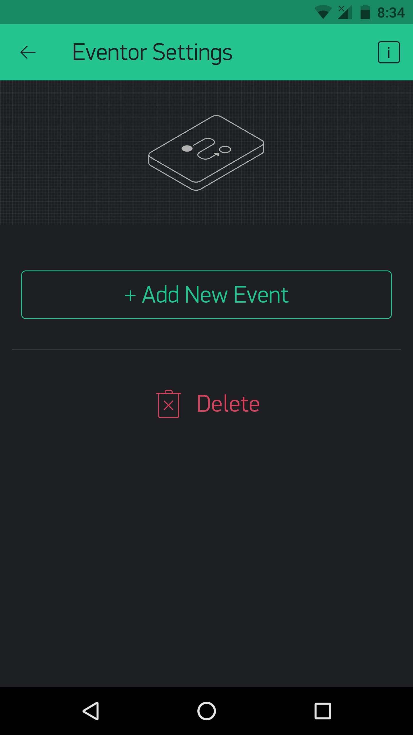
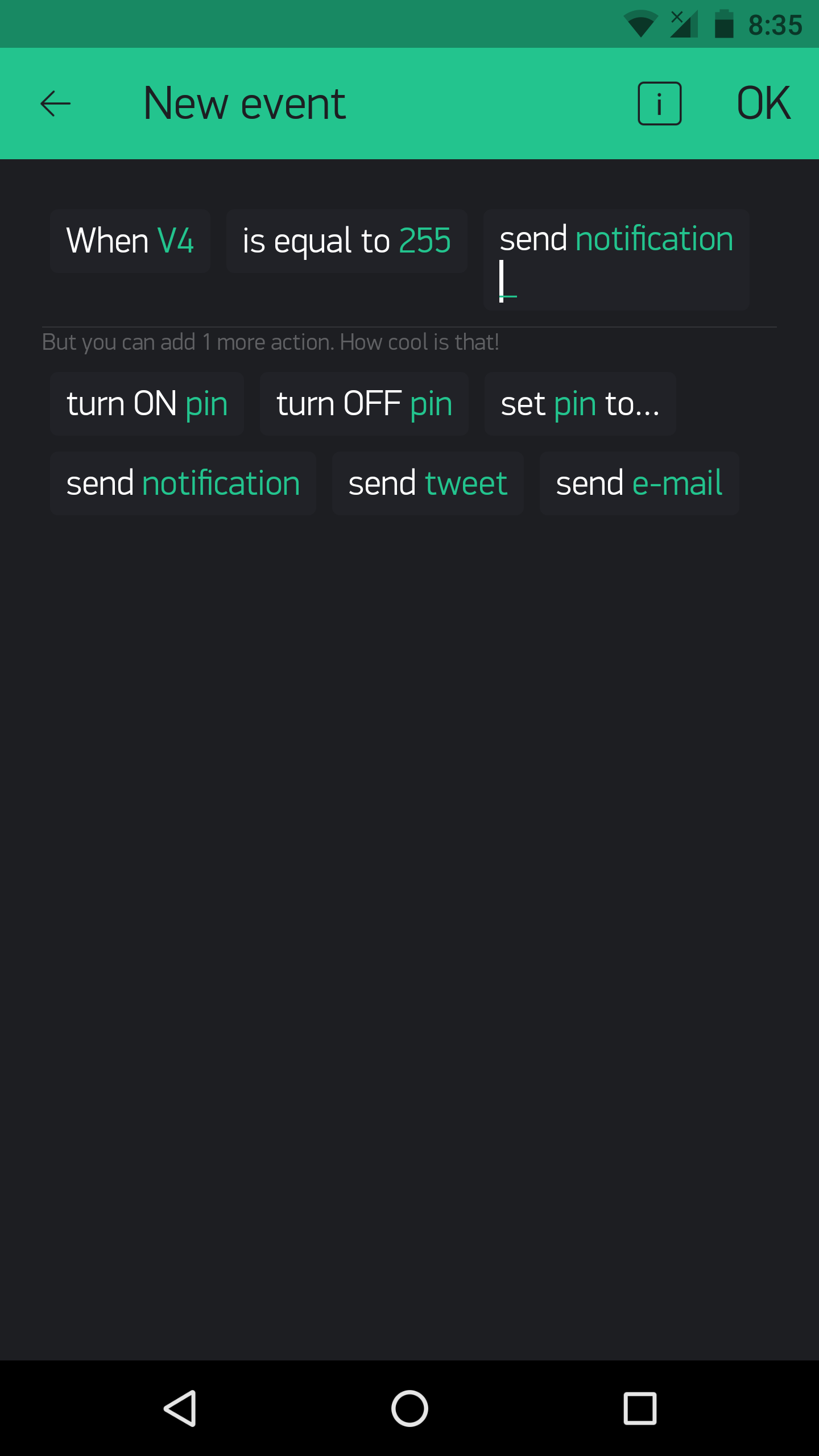
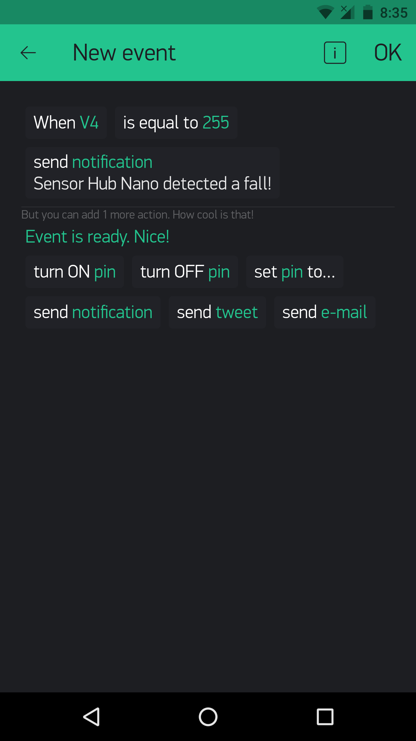
In the above example, the Eventor widget is used to set up a fall detection notification.
Using the Eventor widget to remind is done by this code:
BLYNK_WRITE(vEVENTOR_PIN) {
//Use the Eventor widget to check if it's time to do a task (take medication in this case)
int currentValue =param.asInt(); // 0 to 1
if (currentValue ==1) {
//Do here what you want to when its time for medication
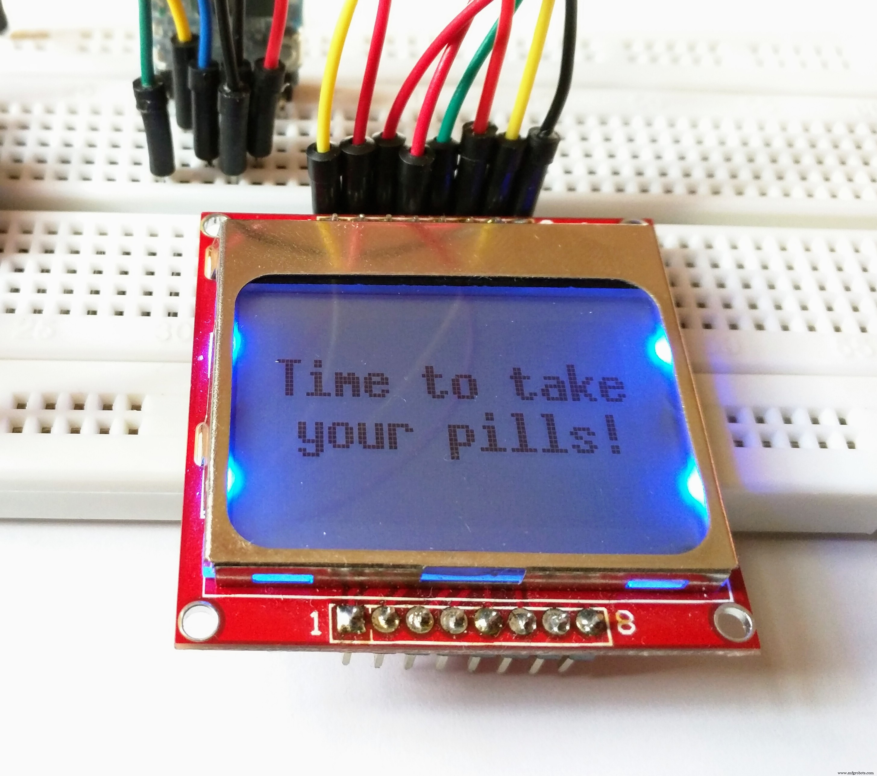
showPillReminder();
playBuzzerReminder();
//This is just a tone, I haven't made it in the main code, but you can if you want!
}
else {
//If it's not the time for medication, do nothing
}
} And the result on the display when it's the time for medication:
The same for exercise:
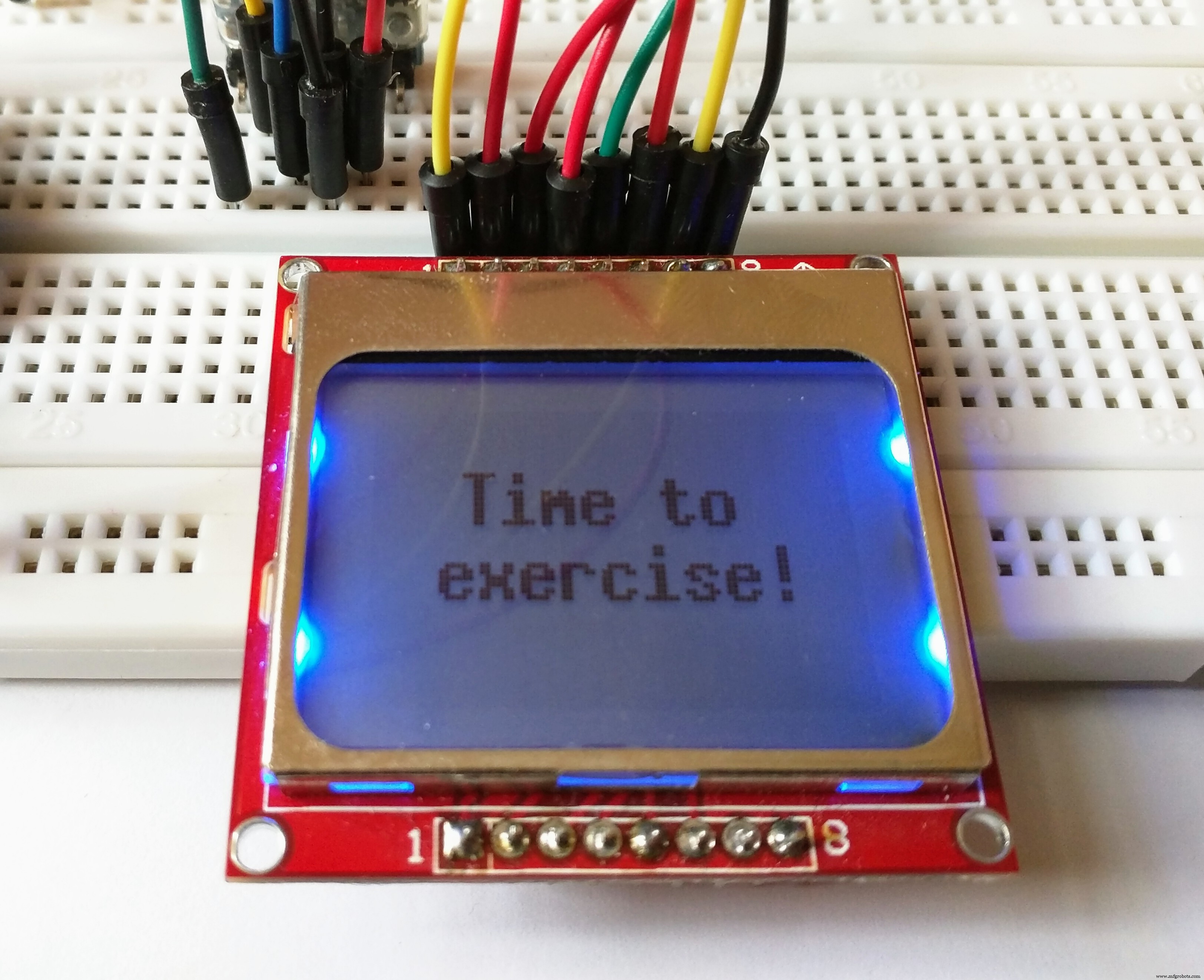
This is done by typing:
showExerciseReminder(); Instead of:
showPillReminder(); The eventor widget could, as said above, be used for a number of things. For example, you could set that an increase in temperature could result in sending an e-mail, and with no code modification!
Using different modes of the Sensor Hub Nano:-
You can test out the use of different modes for the Sensor Hub Nano. Using the following commands:
sendCommand(LOW_ENERGY);
sendCommand(STANDARD_MODE);
sendCommand(HIGH_PRECISION);
Using Blynk to switch modes could be more efficient. For that, set up your Blynk app like this:
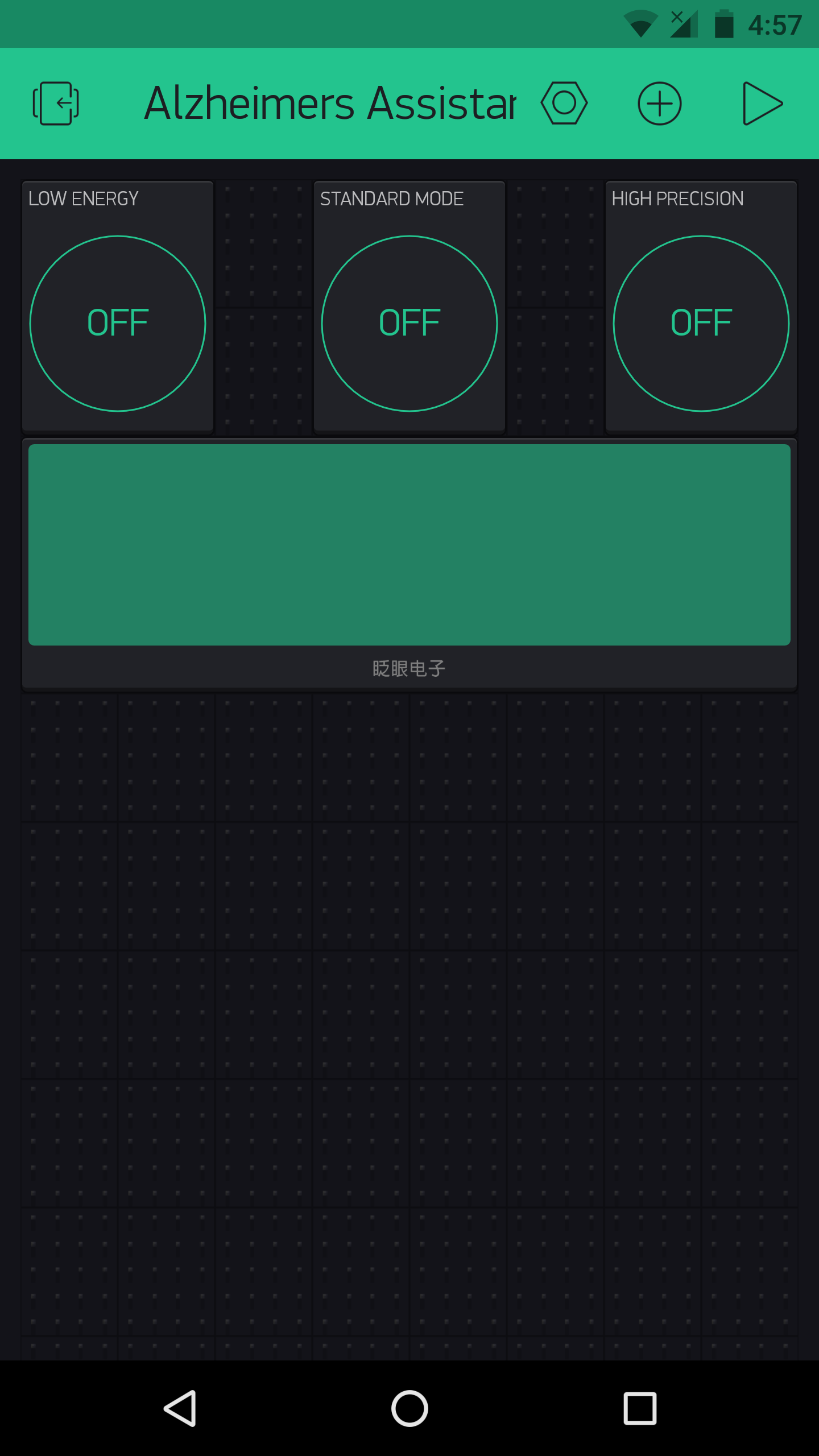
As this had no use for me, I did not add it it in the main code, but you could always do so as needed (The commands are present, you just need to add them with a bit of logic in the main sketch).
Using Blynk and IFTTT:-
Blynk can allow any Arduino project to easily harness the power of IFTTT.

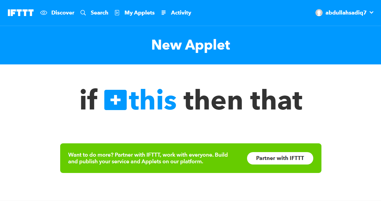
This is because you can use Blynk to send a webhook request to the IFTTT Webhooks channel (previously called Maker channel), and you could create an IFTTT applet which waits for the webhook to be triggered (from the Blynk and Arduino side) and you could get it to trigger anything else in response to that.
A simple example on how to use IFTTT and Blynk with webhooks :
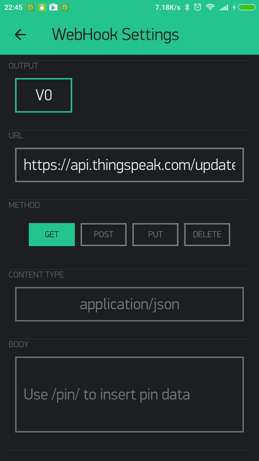
The Blynk webhook widget could be used to send a webhook request like this:
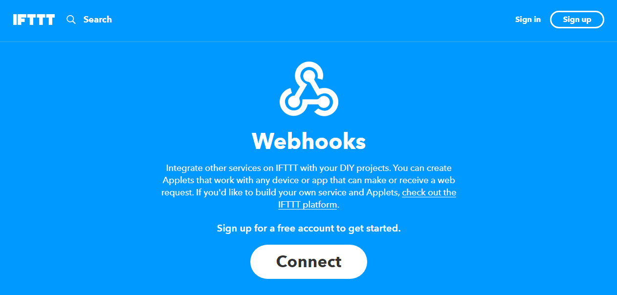
This is the IFTTT webhook channel:
And using webhooks to trigger IFTTT is not the only method. IFTTT can also be triggered by using Blynk to send emails and tweets.
You have now made an applet. Time to test it.
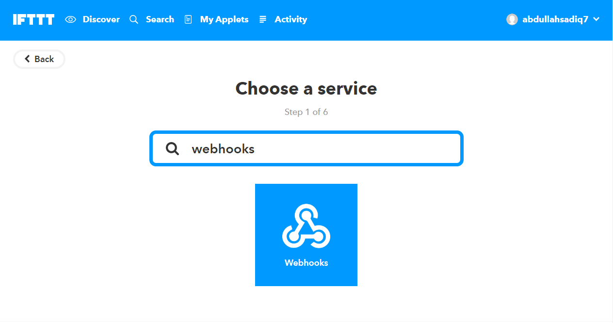
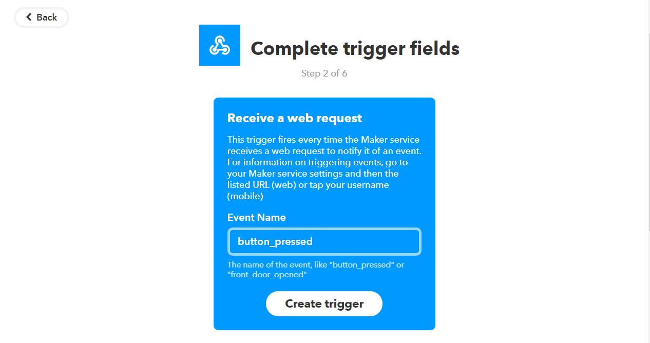
Open "Services" in IFTTT and then select "Webhooks". Go to "Settings" and there you will see a URL. Copy that and open it in a new tab. There, instead of {event}, type the event name (which you set earlier). That was "button_pressed" for me, and so when I click on "Test it", this is the result after a few seconds:
Now that you have confirmed the Webhook works, you can just write the URL in the Blynk webhook settings and get a GET or POST request (through the Blynk webhook widget)
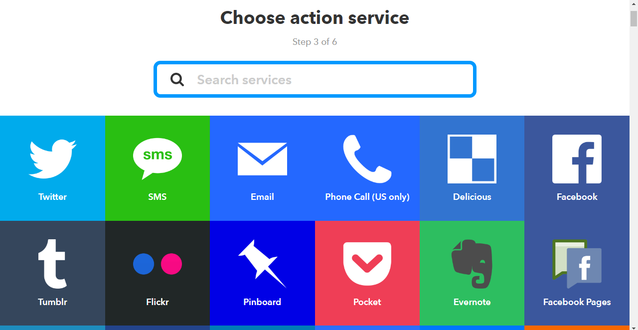
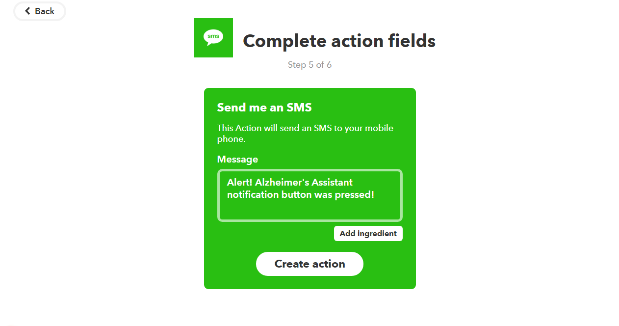
And, instead of SMS, you could just as well use phone calls, or even Twitter and Facebook, if you want, and it's just as simple That is the power of IFTTT.
It's the same thing as my smart home controller project here, and I also discussed it in detail there, but it is a great thing which I couldn't go by without mentioning.
Final Touches
By now, almost all of the electronics part of the project is complete, but a few things still remain. Read on for them, and in the end, I will list the future work which should be done to improve this project.
Battery and charging:
The MKR1000 has a port for a LiPo battery, which means you could attach one. But I don't have one at the moment so I will not be going into that but you should check out the website for the Arduino MKR1000 if you need information on that.
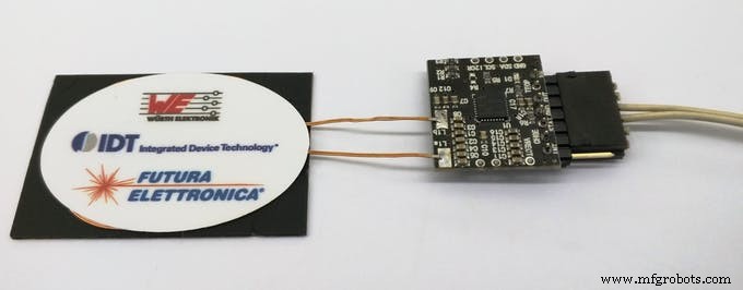
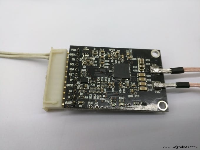
For charging, you have two options, using the MKR1000 USB port directly, and the other one is to use wireless charging, if you have it. I will be using the wireless charging for it. This is because I already have a wireless charging receiver and transmitter made by Futara Elettronica.
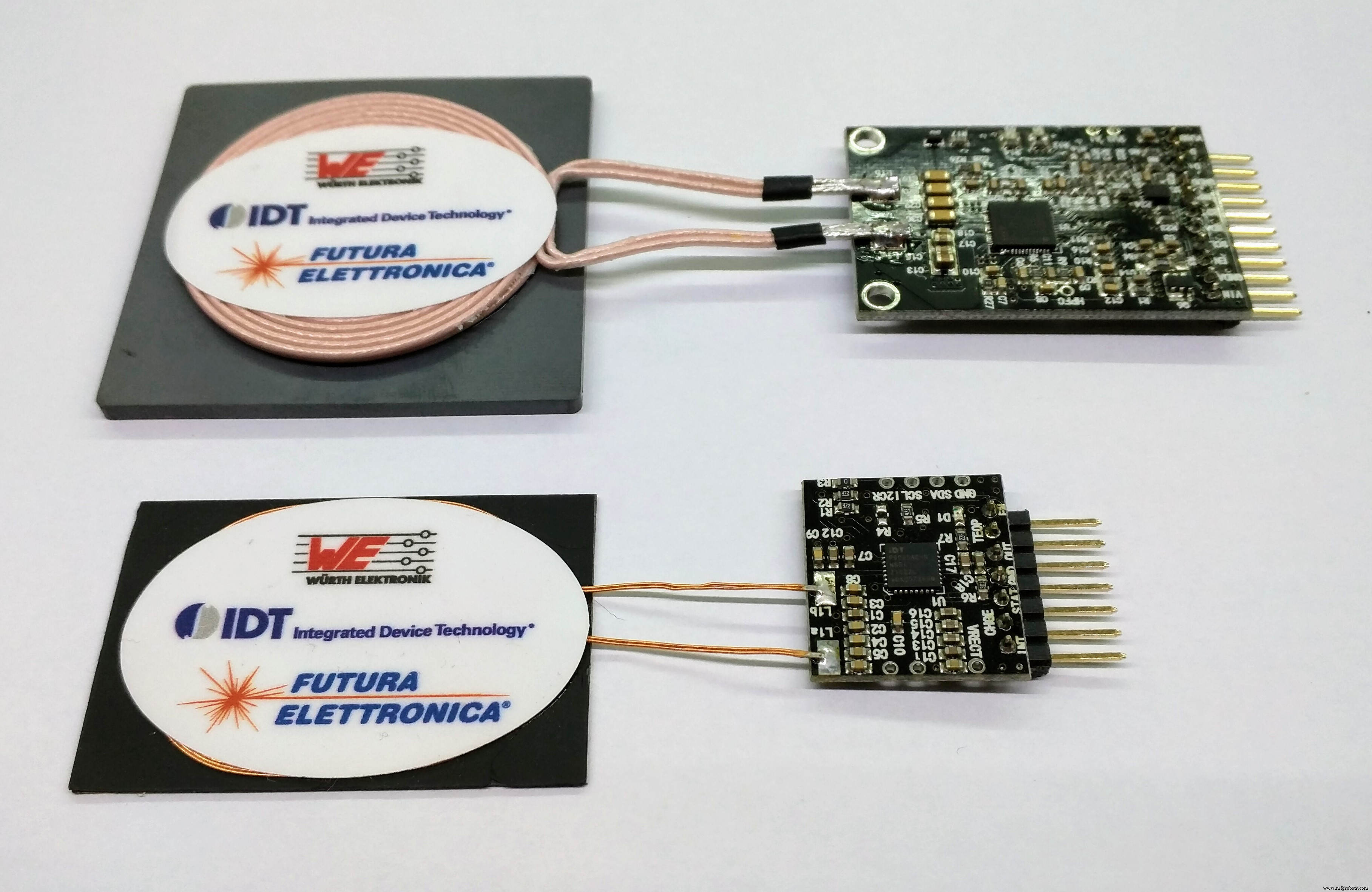
To use the receiver and transmitter, it's just a simple matter of providing the specified voltage to the transmitter. That will be the 'dock', where you can place Alzheimer's Assistant to charge. At the receiver side, you will just have to cut and attach a spare USB micro B cable (which goes to the MKR1000 USB port) and connect the other side to VCC and ground by looking at the pinout.
Just look at the images below to see how to wire it up:
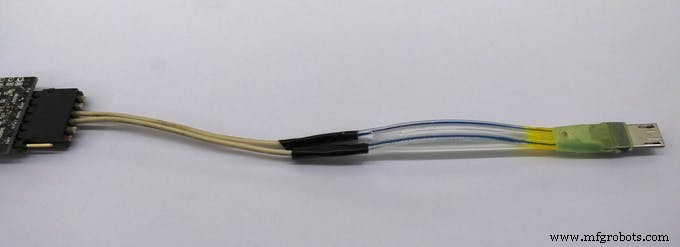
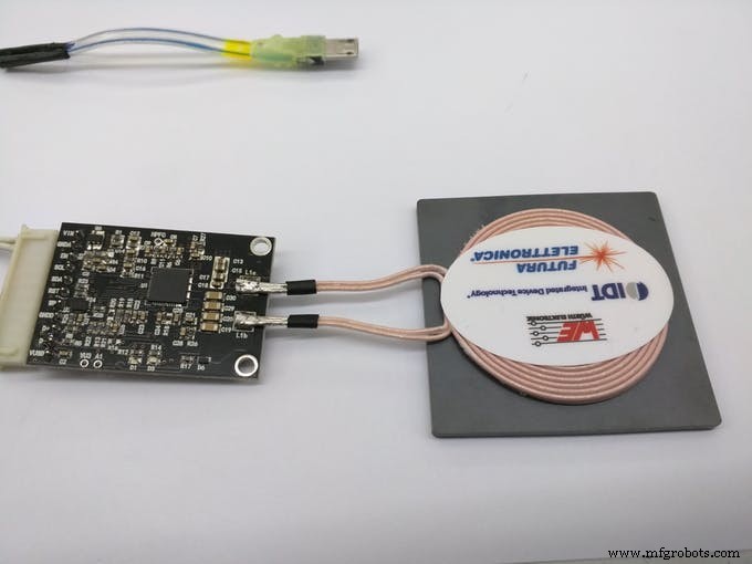
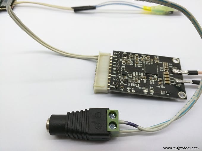
And the end result:
The Enclosure:
As with every project, an enclosure is required for this too, and this how I intend Alzheimer's Assistant to look like:
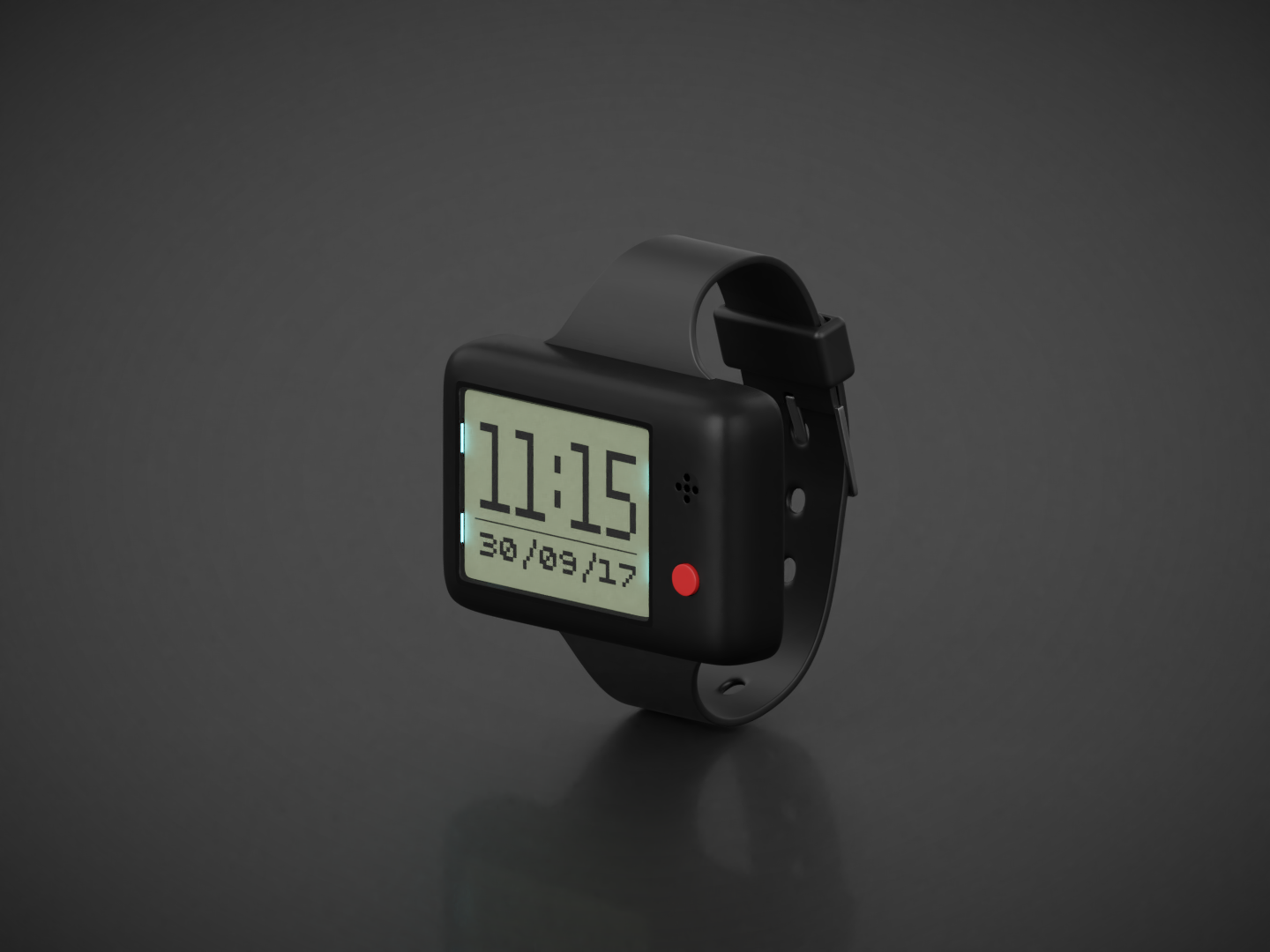
Note:I do not yet have the privilege of a laser cutter or 3D printer, so the STL file is just intended for showing how the final project looks like and it's not to scale.
This concludes the documentation for Alzheimer's Assistant, but I would still like to include the future work section to describe the things which I very much wanted to do for the project, but couldn't, due to some reason or the other.
Future work:
As I said before, these are the things which I wanted to include in the project, which I will add in future, should I get the time:
- Making a proper enclosure for it. Now I am just testing it on a breadboard but if I get access to a laser cutter or 3D printer I will update the documentation with that.
- Using a Bluetooth 4.0 module instead of this one.
- Or even better, using just the DPS310 Sensor instead of the Sensor Hub Nano. This would decrease the cost for the project overall, as it will eliminate the use of the Sensor Hub Nano and the bluetooth module; the DPS310 itself is a available for cheap. It's a matter of editing the main code to get temperature, pressure and altitude values from the DPS310 only, the rest of the part is done.
- Using a secondary sensor to work along with the DPS310 for fall detection and the location detection. This would decrease the occurrence of both, false positive and false negative alerts. Most probably an accelerometer and a motion detector will be needed for both.
- Adding a pulse sensor. I did not have one, so I couldn't add that. It should be a great addition to the project.
- Using a higher resolution display, preferably an OLED. With that, graphics can also be included and that would be pretty neat.
- Working on improving the battery life for the project. This can be done by using a deep sleep mode in the MKR1000, but I haven't used it in the code yet.
Thanks for reading, and hope you liked my project. Feel free to give me your opinions and ideas about the project.
代码
- AT Commands
- Alzheimer's Assistant
AT CommandsArduino
This code is used to configure the HC-05 in AT mode. Details on how to get in AT mode are given in the project description// Original sketch from Martyn Currey's blog here:// http://www.martyncurrey.com/arduino-with-hc-05-bluetooth-module-at-mode///// Sketch modified by me to work with Arduino MKR1000!//// Basic Bluetooth sketch// Connect the HC-05 module and communicate using the serial monitor//// The HC-05 defaults to commincation mode when first powered on.// Needs to be placed in to AT mode// After a factory reset the default baud rate for communication mode is 38400char c =' ';void setup() { // start the serial communication with the host computer Serial.begin(9600); Serial.println("Arduino with HC-05 is ready"); // start communication with the HC-05 using 38400 Serial1.begin(38400); Serial.println("Serial1 started at 38400");}void loop() { // Keep reading from HC-05 and send to Arduino Serial Monitor if (Serial1.available()) { c =Serial1.read(); Serial.write(c); } // Keep reading from Arduino Serial Monitor and send to HC-05 if (Serial.available()) { c =Serial.read(); // mirror the commands back to the serial monitor // makes it easy to follow the commands Serial.write(c); Serial1.write(c); }} Alzheimer's AssistantArduino
The main code for the project, used once you've configured and got the HC-05 to work with Sensor Hub Nano//Including required libraries#include#include #include #include #include #include // You should get Auth Token in the Blynk App.// Go to the Project Settings (nut icon).char auth[] =""; //Enter your Blynk auth token here// Your WiFi credentials.// Set password to "" for open networks.char ssid[] ="";char pass[] ="";//Defining Sensor Hub Nano board commands#define HELLO "$hello id="#define INFO "$info id="#define SENSOR_INFO "$sinfo id=1"#define LOW_ENERGY "$set_mode sid=1;md=mode;val=bg"#define STANDARD_MODE "$set_mode sid=1;md=prs_osr;val=16"#define HIGH_PRECISION "$set_mode sid=1;md=prs_mr;val=32"#define START "$start_sensor id=1"#define STOP "$stop id="//Defining fall and clearance thresholds//You may need to change them, but I found these values to be good#define FALL 0.7#define CLEARANCE 0.2//Defining Blynk virtual pins#define vTEMPERATURE_PIN V0#define vPRESSURE_PIN V1#define vALTITUDE_PIN V2#define vEVENTOR_PIN V3#define vFALL_PIN V4//Declaring required variablesfloat t, p, a, previousA;//Boolean which tells tells if a fall is detected or notboolean fallState;//Variables needed for the fall detection algorithmunsigned long previousMillis =0;const long interv al =1000;//BTconnected is false when not connected and true when connectedboolean BTconnected =false;//Defining BT state and LCD backlight pinsint btStatePin =9;int backlightPin =2;BlynkTimer timer;WidgetRTC rtc;//Nokia 5110 Display wiringU8G2_PCD8544_84X48_F_4W_SW_SPI u8g2(U8G2_R0, /* clock=*/ 7, /* data=*/ 8, /* cs=*/ 3, /* dc=*/ 5, /* reset=*/ 4);void setup() { //Initialize both serial ports:Serial.begin(115200); Serial1.begin(115200); //Setup the timed fuctions timer.setInterval(1000L, sendSensorValues); timer.setInterval(3000L, showTimeAndDate); //Setting up required inputs and outputs pinMode(btStatePin, INPUT); pinMode(backlightPin, OUTPUT); digitalWrite(backlightPin, LOW); u8g2.begin(); showStartMessage();延迟(2000); // wait until the bluetooth module has made a connection while (!BTconnected) { if (digitalRead(btStatePin) ==HIGH) { BTconnected =true; } else { showWaitingFor(); } } initSensorHub(); Blynk.begin(auth, ssid, pass); rtc.begin(); setBlynkWidgets(); showTimeAndDate(); sendCommand(START);}void loop() { Blynk.run();定时器运行(); getSensorValues(); checkIfFalling();}void sendCommand (String sensorCommand) { //This function sends commands through the bluetooth module on the hardware serial port to the the Sensor Hub Nano //For example:"sendCommand(START);", starts the flow of data from the sensor //The full list of commands I know are defined at the top of the sketch Serial1.println(sensorCommand);}void initSensorHub() { //Initialise the Sensor Hub Nano, and give an error if there is any problem String junkVal; sendCommand(INFO); while (Serial1.find("IFX_NanoHub") ==false) { sendCommand(INFO); Serial.println("ERROR"); showErrorMessage(); } junkVal =Serial1.readStringUntil('\n'); junkVal =""; showConnectedMessage(); delay(1500);}void getSensorValues() { //Retrieves the sensor values from the Sensor Hub Nano through the Serial1 port String junkVal; if (Serial1.available()) { junkVal =Serial1.readStringUntil('\n'); junkVal =Serial1.readStringUntil('t'); t =Serial1.parseFloat(); junkVal =Serial1.readStringUntil('p'); p =Serial1.parseFloat(); junkVal =Serial1.readStringUntil('a'); a =Serial1.parseFloat(); junkVal =Serial1.readStringUntil('\n'); }}void sendSensorValues() { //Sending the sensor values to the Blynk server Blynk.virtualWrite(vTEMPERATURE_PIN, t); Blynk.virtualWrite(vPRESSURE_PIN, p); Blynk.virtualWrite(vALTITUDE_PIN, a);}void checkIfFalling() { //Algorithm to check if the patient is falling unsigned long currentMillis =millis(); if ((currentMillis - previousMillis)>=interval) { float diff =previousA - a; if ((diff>=(FALL - CLEARANCE)) &&(diff <=(FALL + CLEARANCE))) { fallState =true; //Here insert what you need to do if fall is detected, such as sending a notification or email with Blynk //Or you could also use IFTTT to call or send an sms to alert the caretaker (more info in the project documentation) Serial.println("Falling"); showFallMessage(); //In this example, vFALL_PIN (virtual pin 4) is set to 255 if fall is detected Blynk.virtualWrite(vFALL_PIN, 255); //You can send a notification using only the notification widget too! //Blynk.notify("DPS310 detected a fall!"); } previousA =a; previousMillis =currentMillis; fallState =false; //Set vFALL_PIN to 0 if a fall isn't detected Blynk.virtualWrite(vFALL_PIN, 0); }}void showStartMessage() { //Shows the start-up message u8g2.clearBuffer(); u8g2.drawRFrame(3, 7, 75, 31, 7); u8g2.setFont(u8g2_font_prospero_bold_nbp_tf); u8g2.drawStr(8, 19, "Alzheimer's"); u8g2.drawStr(12, 35, "Assistant"); u8g2.sendBuffer();}void showWaitingFor() { //Shows the waiting for Sensor Hub Nano message u8g2.clearBuffer(); u8g2.setFont(u8g2_font_prospero_bold_nbp_tf); u8g2.drawStr(9, 15, "Waiting for"); u8g2.drawStr(8, 28, "Sensor Hub"); u8g2.drawStr(22, 41, "Nano !!!"); u8g2.sendBuffer();}void showConnectedMessage() { //Shows the connected message u8g2.clearBuffer(); u8g2.setFont(u8g2_font_7x13B_tf); u8g2.drawStr(0, 10, "Connected to"); u8g2.drawStr(8, 22, "Infineon's"); u8g2.drawStr(7, 34, "Sensor Hub"); u8g2.drawStr(29, 46, "Nano"); u8g2.sendBuffer();}void showErrorMessage() { //Shows the error message u8g2.clearBuffer(); // clear the internal memory u8g2.setFont(u8g2_font_fub14_tf); // choose a suitable font u8g2.drawStr(9, 30, "ERROR"); // write something to the internal memory u8g2.sendBuffer(); // transfer internal memory to the display}void showSensorValues() { //Shows the sensor values on the display char bufT[10]; char bufP[10]; char bufA[10]; String(t).toCharArray(bufT, 10); String(p).toCharArray(bufP, 10); String(a).toCharArray(bufA, 10); u8g2.clearBuffer(); u8g2.setFont(u8g2_font_6x10_tf ); //Display the temperature u8g2.drawStr(0, 10, "T:"); u8g2.drawStr(12, 10, bufT); u8g2.drawStr(73, 10, "C"); u8g2.drawCircle(70, 4, 1, U8G2_DRAW_ALL); u8g2.drawHLine(0, 12, 85); //Display the pressure u8g2.drawStr(0, 26, "P:"); u8g2.drawStr(12, 26, bufP); u8g2.drawStr(60, 26, "mBar"); u8g2.drawHLine(0, 28, 85); //Display the altitude u8g2.drawStr(0, 42, "A:"); u8g2.drawStr(12, 42, bufA); u8g2.drawStr(72, 42, "m"); u8g2.drawHLine(0, 44, 85); //Send the values to the display u8g2.sendBuffer();}void showFallMessage() { //Show the fall detected message u8g2.clearBuffer(); u8g2.setFont(u8g2_font_7x13B_tf); u8g2.drawStr(27, 20, "Fall"); u8g2.drawStr(13, 32, "Detected!"); u8g2.sendBuffer(); delay(1000);}void showPillReminder() { //Show the pill reminder message u8g2.clearBuffer(); u8g2.setFont(u8g2_font_7x13B_tf); u8g2.drawStr(0, 20, "Time to take"); u8g2.drawStr(5, 32, "your pills!"); u8g2.sendBuffer();}void showExerciseReminder() { //Show the exercise reminder message u8g2.clearBuffer(); u8g2.setFont(u8g2_font_7x13B_tf); u8g2.drawStr(16, 20, "Time to"); u8g2.drawStr(12, 32, "exercise!"); u8g2.sendBuffer();}void showTimeAndDate() { //Displays the time and date from the RTC widget in Blynk in 24 hours format if (year() ==1970) { //Serial.println("Time not yet synced"); } else if (year() !=1970) { char bufHours[3]; char bufColon[2]; char bufMinutes[3]; char bufDate[11]; String currentHours =String(hour()); String colon =":"; String currentMinutes =String(minute()); String currentDate =String(day()) + "/" + month() + "/" + year(); String(currentHours).toCharArray(bufHours, 3); String(colon).toCharArray(bufColon, 2); String(currentMinutes).toCharArray(bufMinutes, 3); String(currentDate).toCharArray(bufDate, 11); u8g2.clearBuffer(); u8g2.setFont(u8g2_font_inr33_mf); u8g2.drawStr(30, 30, bufColon); u8g2.setFont(u8g2_font_logisoso32_tn); u8g2.drawStr(0, 32, bufHours); u8g2.drawStr(45, 32, bufMinutes); u8g2.setFont(u8g2_font_saikyosansbold8_8n); u8g2.drawHLine(0, 35, 85); u8g2.drawStr(0, 46, bufDate); u8g2.sendBuffer(); }}BLYNK_WRITE(vEVENTOR_PIN) { //Use the Eventor widget to check if it's time to do a task (take medication in this case) int currentValue =param.asInt(); // 0 to 1 if (currentValue ==1) { showPillReminder(); //Serial.println("Time to take your pills"); } else { //Serial.println("Not the time to take pills"); }}void setBlynkWidgets() { //This sets the colour of each widget in the Blynk app //You may remove this from the sketch if you want to set colours manually through the Blynk app //You could also specifiy the hex value of each colour you need //Set temperature widget color to white Blynk.setProperty(vTEMPERATURE_PIN, "color", "#FFFFFF"); //Set pressure widget color to blue Blynk.setProperty(vPRESSURE_PIN, "color", "#00BBFF"); //Set altitude widget color to yellow Blynk.setProperty(vALTITUDE_PIN, "color", "#FFFF00");}BLYNK_CONNECTED() { //Synchronize time on connection, if connection drops rtc.begin();}
定制零件和外壳
This is just to show how I intend the enclosure to look like. It's not at all to scale!示意图
This diagram is used when getting your HC-05 in AT mode and configuring it, using the Arduino MKR1000. Fritzing diagram for the bare-bones project to function
 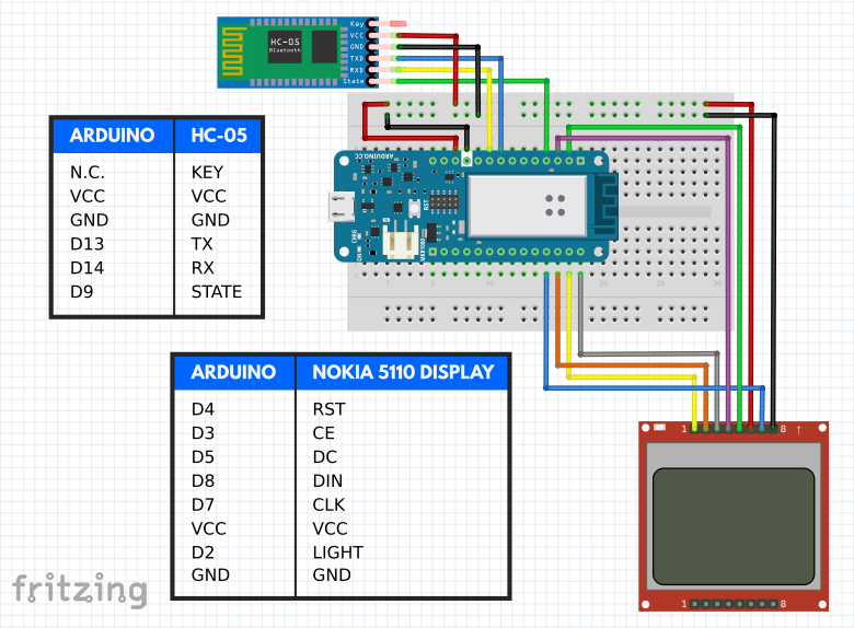 Document listing AT commands for the HC-05
制造工艺