

Coin Op 个人自动售货机
组件和用品
| × | 4 | ||||
| × | 1 | ||||
| × | 1 | ||||
| × | 1 | ||||
| × | 1 | ||||
| × | 1 | ||||
 |
| × | 1 | |||
| × | 1 | ||||
 |
| × | 1 | |||
| × | 1 | ||||
| × | 1 | ||||
| × | 2 | ||||
| × | 1 | ||||
| × | 1 |
必要的工具和机器
| ||||
 |
| |||
 |
|
应用和在线服务
 |
|
关于这个项目
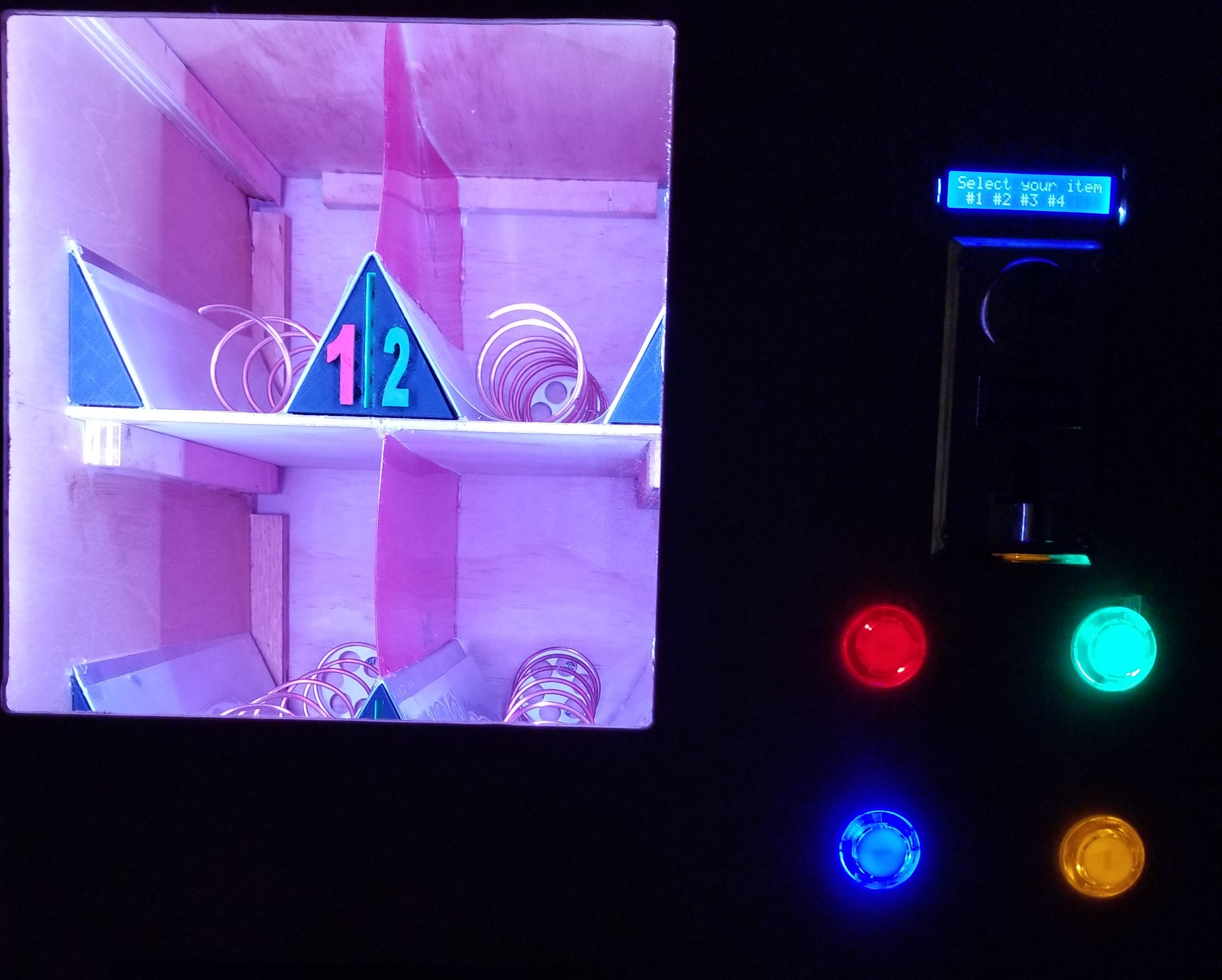
个人自动售货机
该项目是逐步构建个人自动售货机。自动售货机可以装满您最喜欢的零食,也可以带到办公室,这样您就可以与您的团队分享一些零食。看一看,让我知道你的想法。
构建机器:
在本文中我将参考机器的图表,因此请参阅图表以进行澄清/理解。
机器尺寸为 21"W x 18"D x 24 1/4"H(箱体尺寸)
2 个面板 18"D x 23 3/4"H (侧面)
2 个面板 21"W x 18"D(顶部和底部)
2 个面板 21"W x 24 1/4"H (前后)
分隔墙为 18"D x 23 3/4"H
内部搁板为 13"W x 12"D(乘以 2,上下搁板)
货架相距 8 英寸,宽 13 英寸,深 12 英寸
面板图上的每个蓝色块都是一个 ¾”W x ¾”H 安装点,与面板一样深
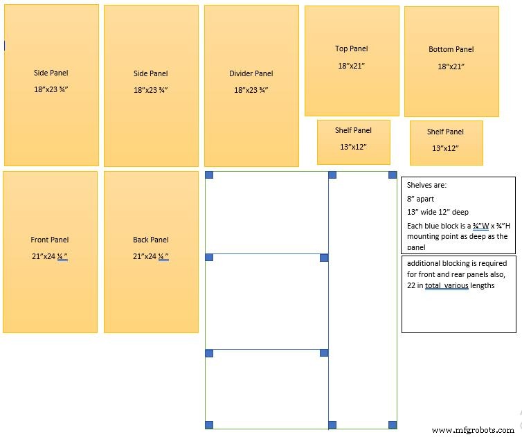
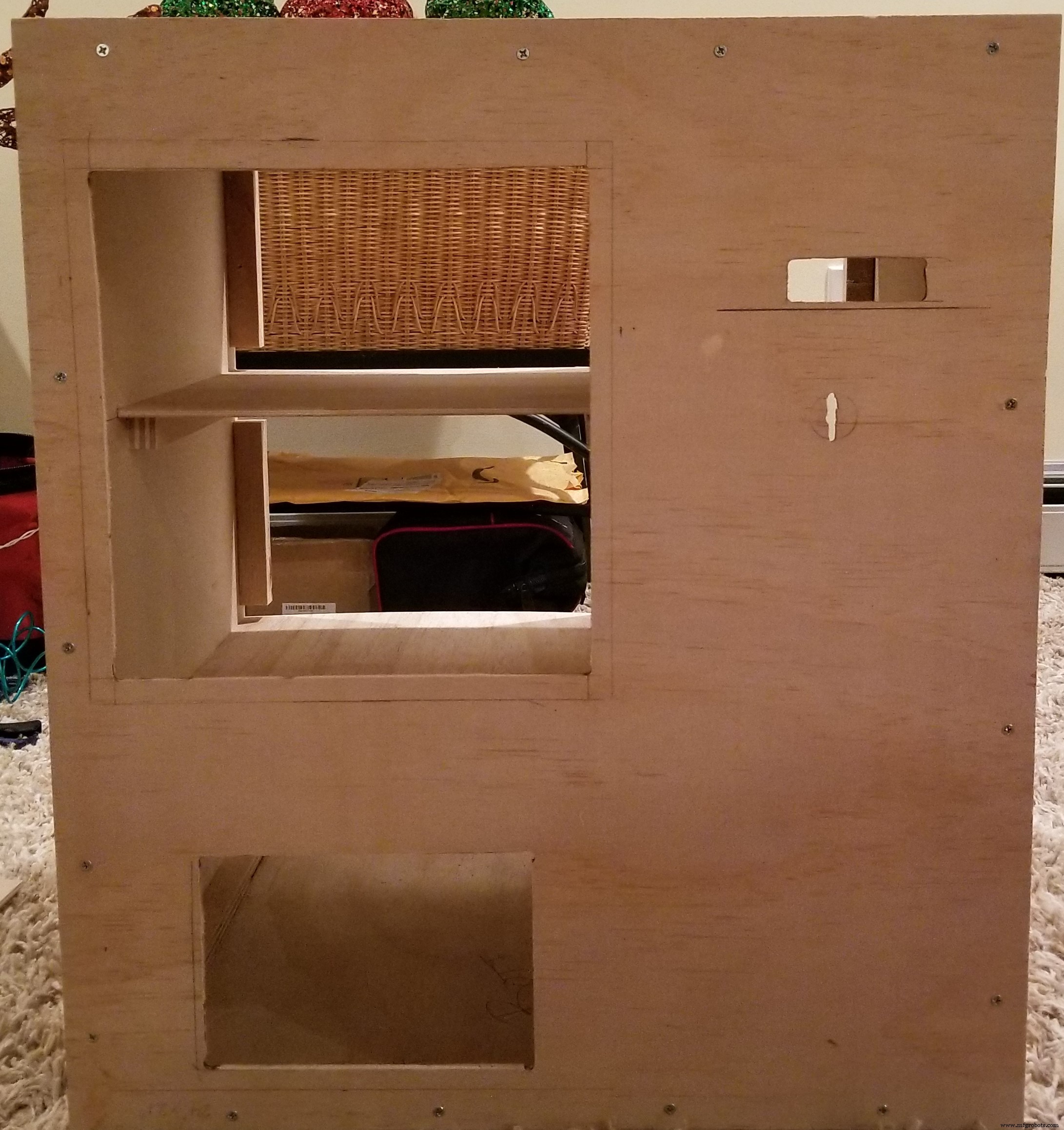
如图所示组装盒子,此处在每个连接点使用 3/4" 挡块。注意侧壁位于底板的顶部和顶板下方。围墙的尺寸应为 21"W由 24 1/4" 高。
安装前需要设置分隔墙。从顶部向下测量 16 1/4" 并在那里为底部搁板安装挡块。从顶部向下测量 8 1/4" 并为顶部搁板安装挡块。在左墙上完成这些步骤(从机器正面看),这样您就可以安装顶部和底部搁板的挡块。
**** 注意需要先安装底部搁板,否则很难固定到挡块上。
为搁板安装挡块后,使用 13" x 12" 面板并在每组挡块上安装一个。这将自动将分隔墙设置在适当的位置。然后在分隔壁右侧的顶部和底部固定挡块。然后将其固定到顶部和底部面板这将完全确定您的结构。
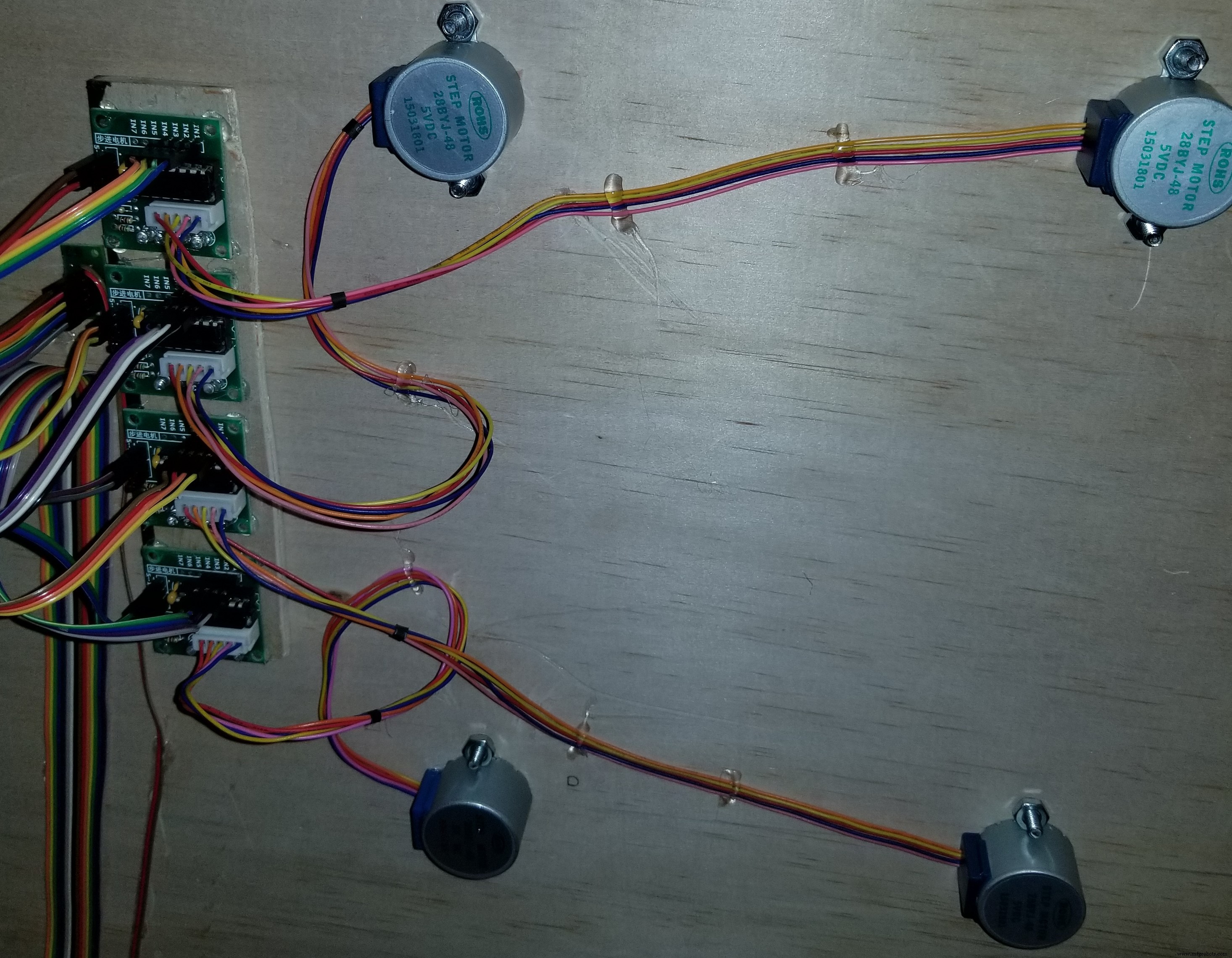
安装后面板并准备安装电机。确保打印了线圈轮,以便您可以测量它们并设置钻孔。测量轮子并在高度上增加 1/4" 以便为线圈旋转留出空间。您可能需要根据您的材料进行调整。在架子上测量超过 6 1/2" 以标记其中间。测量超过 3 1/4" 以找到每个搁板部分的中心。使用您刚才记录的高度测量来找到钻孔点。钻一个孔,这样您就可以将车轮连接到电机而不会摩擦轮轴板。完成安装电机并拧入紧固件。
设置电机继电器:
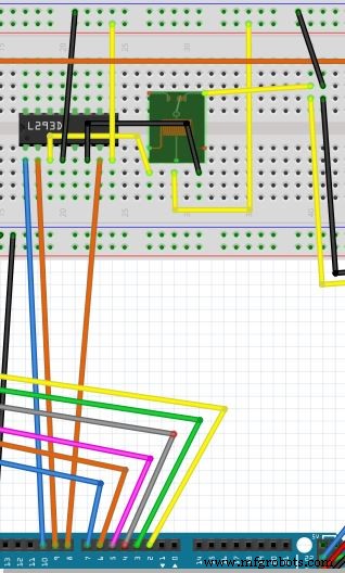
按如下方式连接引脚。使用芯片L293D(左边的缺口)(在电路图中)这样你就可以控制继电器。这将允许您将电机连接到电源。
(从左到右开始)
引脚 1 连接到控制器上的引脚插座 10(电路图中)
Pin2连接到控制器上的pin socket 9(电路图中)
引脚 3 连接到继电器的正极(3 个引脚面向您,引脚在左侧)(电路图中)
引脚 4 连接到面包板上的 12V 地(电路图中)
Pin 5 未使用(电路图中)
引脚 6 连接到继电器的接地侧(3 个引脚面向您,引脚在右侧)(电路图中)
引脚 7 连接到控制器上的引脚插座 8(电路图中)
引脚 8 连接到面包板上的 +12V(电路图中)
将继电器的中间引脚连接到面包板上的+12V(电路图中)
将继电器上的右侧引脚(3 个引脚面向您,引脚在右侧)连接到通往电机驱动器的正极(电路图中)
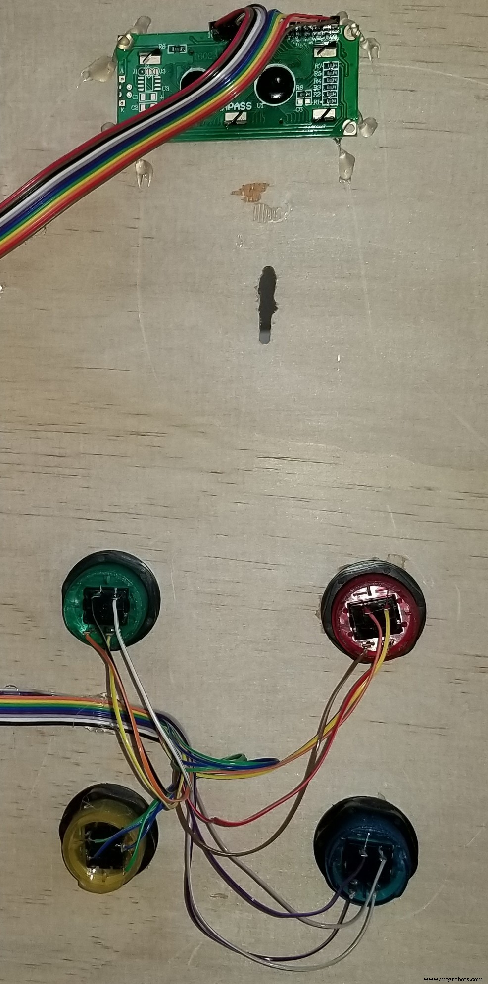
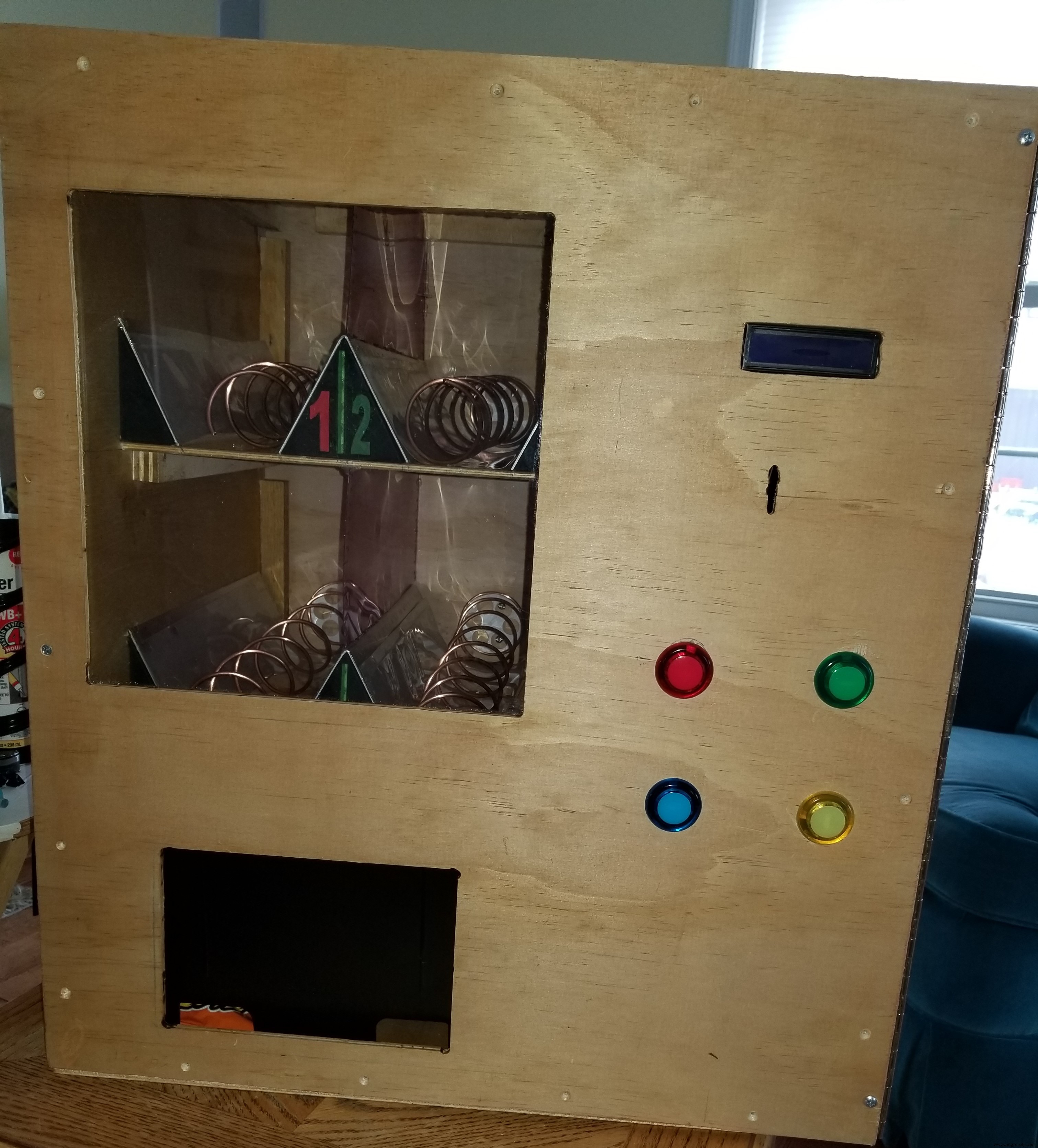
屏幕和按钮安装:屏幕 - 选择机器右侧的一个点(从正面看机器)并标记需要为屏幕显示部分制作的孔 (2.53937" x 0.5708661) 按钮- 在机器右侧选择一个点(从正面看机器)并标出需要为 4 个按钮制作的孔。如果使用完全相同的按钮,孔需要为 1.10236"零件清单。我喜欢用比需要的更小的钻头和砂纸把它弄到需要的尺寸。
请记住,您需要确保所有连接都位于与上图中完全相同的位置。图中显示的 LED 是内置于按钮中的 LED。图表将它们分开显示,但这仅用于显示并使原理图更易于阅读。
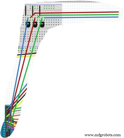
将每个电机连接到随附的驱动器。然后使用以下步骤将每个驱动程序连接到控制器:
电机设置:
电源应连接到面包板的 12V 侧。这个电源来自我们最后准备的ATX电源。然后将驱动器上的 4 个“输入”引脚连接到控制器。这些引脚如下
********* 请勿连接到此块中的前 2 个引脚,它们是 5V 引脚 - 本项目中未使用 *********
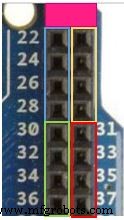
电机 1:蓝色引脚 22、24、26、28(电路图中)
电机 2:黄色引脚 23、25、27、29(电路图中)
电机 3:绿色引脚 30、32、34、36(电路图中)
电机 4:红色引脚 31、33、35、37(电路图中)
按钮连接:
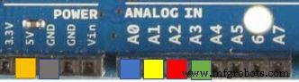
将按钮 1 的一侧连接到 5v 电源,另一侧连接到接地的 220 电阻以及模拟引脚 A0(电路图中)
将按钮 2 的一侧连接到 5v 电源,另一侧连接到接地的 220 电阻以及模拟引脚 A1(电路图中)
将按钮 3 的一侧连接到 5v 电源,另一侧连接到接地的 220 电阻以及模拟引脚 A2(电路图中)
将按钮 4 的一侧连接到 5v 电源,另一侧连接到接地的 220 电阻以及模拟引脚 A3(电路图中)
液晶屏:
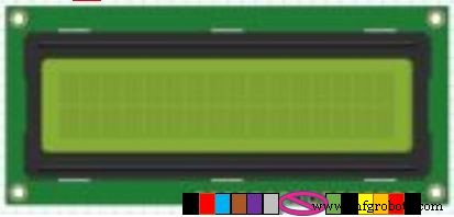
将屏幕连接到面包板的 5v 侧作为电源和地
引脚如下:
引脚 1:接地(电路图中)
引脚 2:连接到 5v 电源(电路图中)
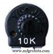
引脚 3:连接到可调电位器(如下图)左下方引脚接地,右下方引脚接地,顶部引脚连接 LCD 上的引脚 3(在电路图中,这是您在 LCD 上设置对比度的方法,因此文本清晰且干净)
引脚 4:第一个信号引脚到控制器引脚插座 2(电路图中)
引脚 5:接地(电路图中)
引脚 6:第二个信号引脚到控制器引脚插座 3(电路图中)
引脚 7:未使用
引脚 8:未使用
引脚 9:未使用
引脚 10:未使用
引脚 11:第三个信号引脚到控制器引脚插座 4(电路图中)
引脚 12:第四个信号引脚到控制器引脚插座 5(电路图中)
引脚 13:第五个信号引脚到控制器引脚插座 6(电路图中)
引脚 14:第六个信号引脚到控制器引脚插座 7(电路图中)
Pin 15:连接到 5v 电源(电路图中)
引脚 16:接地(电路图中)
ATX 电源 :
只切断为设备供电所需的电线。其他电线在塑料连接器中更安全,如果需要,您可以将其用于其他项目。
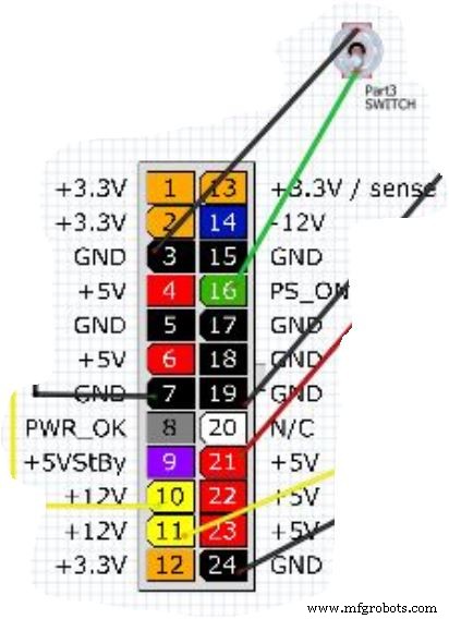
ATX 引脚:
切割并剥去(接地)黑色线针 3 和(信号)绿色线针 16。将这些线连接到开关上,以便您可以打开和关闭机器(电路图中)
切割并剥去(接地)黑色线脚 7 和(+12V)黄色线脚 10。将这些电线连接到面包板的 12v 侧,用黄色和黑色连接指定。 (电路图中)
切割并剥去(接地)黑线针脚 24 和(+12V)黄线针脚 11。将这些线连接到兼容的连接器,为 Arduino 板供电(电路图中)
切割并剥去(接地)黑色线脚 19 和(+5V)红色线脚 21。将这些电线连接到面包板的 5V 侧(电路图中)
隔板和线圈:
这是设置搁板和挤出机的方法。
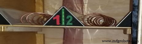
搁板 - 在距左侧壁(从正面看机器)或分隔壁的中间点 6 1/2" 处,应有上述步骤的标记。使用扁平金属并将其弯曲成三角形。看起来就像这样“^”这将作为你的中间分隔线。将三角形居中放在架子上的中间标记上。重复第二个架子。用热胶固定到位。我也把幻灯片放在两边,但它们是可选的。
线圈 - 要创建线圈,首先要找到一个 1 1/2" 的管子。管子、填缝管、喷漆罐或类似的物体都可以。一个技巧是用橡皮筋从上到下缠绕在长度上管的。沿着管子两侧的带子的每一侧沿着直线向下。一旦两边都有平行线,用卷尺标记下一个点。选择一侧并测量 1" 并标记它,然后从那里测量 2" 标记它并一直沿着管子留出 2" 的空间。现在,在管的另一侧仅标记 2" 间隔。开始在管的 1" 侧制作线圈并继续制作线圈,使其接触管两侧的每个标记。这将使您在梯级之间有 2" 的间隙。对于大多数物品来说应该足够大。如果您打算将它用于糖果,将线圈缩短到 1",只需将上述公式减少一半。
将线圈连接到 3D 打印车轮。请记住,有一些制造的轮子可以工作。看看亚马逊。
在线圈的 1" 侧折叠这个线圈,使其形成一个圆圈。然后将直径缩短到比车轮略小。一旦线圈准备好将其安装在车轮边缘。这应该会导致线圈压缩轮的边缘并防止其滑动。一旦您对合身感到满意,取一小滴热胶并将其放在线圈末端的轮子上以将其固定到位。
LED 灯条:
将正极连接到面包板 12V 侧的 +12V 引脚。将地线连接到面包板12V侧的地脚(图中未显示)
请提出您的所有问题,以便我可以协助更新,使这个项目成为有史以来最简单的项目。
代码
- 自动售货机 - 无需更换 LED 灯
- 自动售货机 - 带有不断变化的 LED 灯
- Coin Acceptor 和完整的代码
自动售货机 - 无需更换 LED 灯Arduino
完成和理解项目所需的一切// Display#includeLiquidCrystal lcd(2, 3, 4, 5, 6, 7);//Stepper Library#include / /包括步进电机库//继电器设置#define ENABLE 10#define DIRA 8#define DIRB 9//Define "i"int i;//定义引脚部分//Stepper Connect 1int stepIN1Pin =22;int stepIN2Pin =24;int stepIN3Pin =26;int stepIN4Pin =28;//Stepper Connect 2int stepIN1Pin1 =23; int stepIN2Pin1 =25;int stepIN3Pin1 =27;int stepIN4Pin1 =29;//Stepper Connect 3int stepIN1Pin2 =30;int stepIN2Pin2 =32;int stepIN3Pin2 =34;int stepIN4Pin2 =36;//步进连接3int stepIN1Pin2 =30; =33;int stepIN3Pin3 =35;int stepIN4Pin3 =37;//定义stepsint stepsPerRevolution =2048; // 每转步数//定义按钮引脚端口const int button1Pin =A0; // 按钮 1 模拟引脚 A0const int button2Pin =A1; // 按钮 2 模拟引脚 A1const int button3Pin =A2; // 按钮 3 模拟引脚 A2const int button4Pin =A3; // Push Button 4 Analog Pin A3//定义每个步进器// 1Stepper myStepper0(stepsPerRevolution, stepIN1Pin, stepIN3Pin, stepIN2Pin, stepIN4Pin);//2Stepper myStepper1(stepsPerRevolution, stepIN1Pin1, stepIN3Pin1, stepIN2Pin1, stepIN2Pin);//StepIN4Pin stepsPerRevolution, stepIN1Pin2, stepIN3Pin2, stepIN2Pin2, stepIN4Pin2);//4Stepper myStepper3(stepsPerRevolution, stepIN1Pin3, stepIN3Pin3, stepIN2Pin3, stepIN4Pin3);void setup() { // 分配按钮引脚输入:pinMode(button1P); pinMode(button2Pin,输入); pinMode(button3Pin,输入); pinMode(button4Pin,输入); // 分配引脚输出 pinMode(ENABLE, OUTPUT); pinMode(DIRA,输出); pinMode(DIRB,输出); // 分配步进速度 myStepper0.setSpeed(15); myStepper1.setSpeed(15); myStepper2.setSpeed(15); myStepper3.setSpeed(15); //初始化液晶显示器lcd.begin(16, 2);液晶显示器(); lcd.setCursor(0, 0); lcd.print("选择你的项目"); lcd.setCursor(0, 1); lcd.print(" #1 #2 #3 #4");}void loop() { // 读取按钮赋值 int button1State, button2State, button3State, button4State; button1State =digitalRead(button1Pin); button2State =digitalRead(button2Pin); button3State =digitalRead(button3Pin); button4State =digitalRead(button4Pin); digitalWrite(ENABLE, HIGH);// 设置状态为 (i=0;i<5;i++); // 定义按下按钮 1 时的动作 if (((button1State ==LOW) &&!(button2State ==LOW)))// 如果我们按下按钮 1 或按钮 2 {digitalWrite(DIRA,HIGH); //启用中继digitalWrite(DIRB,LOW);液晶显示器(); lcd.setCursor(2, 0); lcd.print("配药"); lcd.setCursor(3, 1); lcd.print("你的物品"); myStepper0.step(stepsPerRevolution); //运行电机lcd.clear(); lcd.setCursor(2, 0); lcd.print("请收下"); lcd.setCursor(3, 1); lcd.print("你的物品");延迟(2500); lcd.setCursor(0, 0); lcd.print("按钮状态 1"); lcd.setCursor(2, 1); lcd.print("1 2 3 或 4");数字写入(DIRA,低); //断开继电器digitalWrite(DIRB,LOW); } // 定义按下按钮 2 时的动作 if (((button2State ==LOW) &&!(button1State ==LOW))) // 如果我们按下按钮 1 或按钮 2 {digitalWrite(DIRA,HIGH); //启用中继digitalWrite(DIRB,LOW);液晶显示器(); lcd.setCursor(2, 0); lcd.print("配药"); lcd.setCursor(3, 1); lcd.print("你的物品"); myStepper1.step(stepsPerRevolution);//运行电机lcd.clear(); lcd.setCursor(2, 0); lcd.print("请收下"); lcd.setCursor(3, 1); lcd.print("你的物品");延迟(2500); lcd.setCursor(0, 0); lcd.print("按钮状态 2"); lcd.setCursor(2, 1); lcd.print("1 2 3 或 4");数字写入(DIRA,低); //断开继电器digitalWrite(DIRB,LOW); } // 定义按下按钮 3 时的动作 if (((button3State ==LOW) &&!(button4State ==LOW))) // 如果我们按下按钮 1 或按钮 2 {digitalWrite(DIRA,HIGH); //启用中继digitalWrite(DIRB,LOW);液晶显示器(); lcd.setCursor(2, 0); lcd.print("配药"); lcd.setCursor(3, 1); lcd.print("你的物品"); myStepper2.step(stepsPerRevolution);//运行电机lcd.clear(); lcd.setCursor(2, 0); lcd.print("请收下"); lcd.setCursor(3, 1); lcd.print("你的物品");延迟(2500); lcd.setCursor(0, 0); lcd.print("按钮状态 3"); lcd.setCursor(2, 1); lcd.print("1 2 3 或 4");数字写入(DIRA,低); //断开继电器digitalWrite(DIRB,LOW); } // 定义按下按钮 4 时的动作 if (((button4State ==LOW) &&!(button3State ==LOW))) // 如果我们按下按钮 1 或按钮 2 {digitalWrite(DIRA,HIGH); //启用中继digitalWrite(DIRB,LOW);液晶显示器(); lcd.setCursor(2, 0); lcd.print("配药"); lcd.setCursor(3, 1); lcd.print("你的物品"); myStepper3.step(-stepsPerRevolution);//运行电机lcd.clear(); lcd.setCursor(2, 0); lcd.print("请收下"); lcd.setCursor(3, 1); lcd.print("你的物品");延迟(2500); lcd.setCursor(0, 0); lcd.print("按钮状态 4"); lcd.setCursor(2, 1); lcd.print("1 2 3 或 4");数字写入(DIRA,低); //断开继电器digitalWrite(DIRB,LOW); }}
自动售货机 - 带有不断变化的 LED 灯C#
看视频!// Display#includeLiquidCrystal lcd(2, 3, 4, 5, 6, 7);//Stepper Library#include //include步进电机库//继电器设置#define ENABLE 10#define PinA 8#define PinB 9#define REDPIN 38#define GREENPIN 39#define BLUEPIN 40//Define "i"int i;//Define "RGB"int r, g , b;//定义引脚部分//Stepper Connect 1int stepIN1Pin =22;int stepIN2Pin =24;int stepIN3Pin =26;int stepIN4Pin =28;//Stepper Connect 2int stepIN1Pin1 =23;int stepIN2Pin1 =25;int stepIN27Pin1;int stepIN4Pin1 =29;//步进连接3int stepIN1Pin2 =30;int stepIN2Pin2 =32;int stepIN3Pin2 =34;int stepIN4Pin2 =36;//步进连接4int stepIN1Pin3 =31;int stepIN2Pin3 =33Pin3; stepIN4Pin3 =37;//定义stepsint stepsPerRevolution =2048; // 每转步数//定义按钮引脚端口const int button1Pin =A0; // 按钮 1 模拟引脚 A0const int button2Pin =A1; // 按钮 2 模拟引脚 A1const int button3Pin =A2; // 按钮 3 模拟引脚 A2const int button4Pin =A3; // Push Button 4 Analog Pin A3//定义每个步进器// 1Stepper myStepper0(stepsPerRevolution, stepIN1Pin, stepIN3Pin, stepIN2Pin, stepIN4Pin);//2Stepper myStepper1(stepsPerRevolution, stepIN1Pin1, stepIN3Pin1, stepIN2Pin1, stepIN2Pin);//StepIN4Pin stepsPerRevolution, stepIN1Pin2, stepIN3Pin2, stepIN2Pin2, stepIN4Pin2);//4Stepper myStepper3(stepsPerRevolution, stepIN1Pin3, stepIN3Pin3, stepIN2Pin3, stepIN4Pin3);void setup() { // 分配按钮引脚输入:pinMode(button1P); pinMode(button2Pin,输入); pinMode(button3Pin,输入); pinMode(button4Pin,输入); // 分配引脚输出 pinMode(ENABLE, OUTPUT);引脚模式(引脚A,输出); pinMode(PinB,输出); //LED 灯条引脚设置 pinMode(REDPIN, OUTPUT); pinMode(绿色PIN,输出); pinMode(BLUEPIN, OUTPUT); // 分配步进速度 myStepper0.setSpeed(15); myStepper1.setSpeed(15); myStepper2.setSpeed(15); myStepper3.setSpeed(15); //初始化液晶显示器lcd.begin(16, 2);液晶显示器(); lcd.setCursor(0, 0); lcd.print("选择你的项目"); lcd.setCursor(0, 1); lcd.print(" #1 #2 #3 #4");模拟写入(REDPIN,256);模拟写入(绿色密码,256); analogWrite(BLUEPIN, 256);}void loop() { // 读取按钮赋值 int button1State, button2State, button3State, button4State; button1State =digitalRead(button1Pin); button2State =digitalRead(button2Pin); button3State =digitalRead(button3Pin); button4State =digitalRead(button4Pin); digitalWrite(ENABLE, HIGH);// 设置状态为 (i =0; i <5; i++); // 定义按下按钮 1 时的动作 if (((button1State ==LOW) &&!(button2State ==LOW)))// 如果我们按下按钮 1 或按钮 2 { digitalWrite(PinA, HIGH); //接合继电器digitalWrite(PinB, LOW);模拟写入(REDPIN,256);对于 (b =256; b> 0; b--);模拟写入(BLUEPIN, b);对于 (g =256; g> 0; g--);模拟写入(GREENPIN,g);对于 (g =256; g> 0; g--);液晶显示器(); lcd.setCursor(2, 0); lcd.print("配药"); lcd.setCursor(3, 1); lcd.print("你的物品"); myStepper0.step(stepsPerRevolution); //运行电机lcd.clear(); lcd.setCursor(2, 0); lcd.print("请收下"); lcd.setCursor(3, 1); lcd.print("你的物品");延迟(2500); lcd.setCursor(0, 0); lcd.print("按钮状态 1"); lcd.setCursor(2, 1); lcd.print("1 2 3 或 4");对于 (b =0; b <256; b++);模拟写入(BLUEPIN, b);对于 (g =0; g <256; g++);模拟写入(GREENPIN,g);数字写入(引脚A,低); //断开继电器 digitalWrite(PinB, LOW); } // 定义按下按钮 2 时的动作 if (((button2State ==LOW) &&!(button1State ==LOW))) // 如果我们按下按钮 1 或按钮 2 { digitalWrite(PinA, HIGH); //接合继电器digitalWrite(PinB, LOW);模拟写入(绿色密码,256);对于 (b =256; b> 0; b--);模拟写入(BLUEPIN, b);对于 (r =256; r> 0; r--);模拟写入(REDPIN,R);液晶显示器(); lcd.setCursor(2, 0); lcd.print("配药"); lcd.setCursor(3, 1); lcd.print("你的物品"); myStepper1.step(stepsPerRevolution);//运行电机lcd.clear(); lcd.setCursor(2, 0); lcd.print("请收下"); lcd.setCursor(3, 1); lcd.print("你的物品");延迟(2500); lcd.setCursor(0, 0); lcd.print("按钮状态 2"); lcd.setCursor(2, 1); lcd.print("1 2 3 或 4");数字写入(引脚A,低); //断开继电器 digitalWrite(PinB, LOW);对于 (b =0; b <256; b++);模拟写入(BLUEPIN, b);对于 (r =0; r <256; r++);模拟写入(REDPIN,R); } // 定义按下按钮 3 时的动作 if (((button3State ==LOW) &&!(button4State ==LOW))) // 如果我们按下按钮 1 或按钮 2 { digitalWrite(PinA, HIGH); //接合继电器digitalWrite(PinB, LOW);模拟写入(BLUEPIN,256);对于 (r =256; r> 0; r--);模拟写入(REDPIN,R);对于 (g =256; g> 0; g--);模拟写入(GREENPIN,g);液晶显示器(); lcd.setCursor(2, 0); lcd.print("配药"); lcd.setCursor(3, 1); lcd.print("你的物品"); myStepper2.step(stepsPerRevolution);//运行电机lcd.clear(); lcd.setCursor(2, 0); lcd.print("请收下"); lcd.setCursor(3, 1); lcd.print("你的物品");延迟(2500); lcd.setCursor(0, 0); lcd.print("按钮状态 3"); lcd.setCursor(2, 1); lcd.print("1 2 3 或 4");数字写入(引脚A,低); //断开继电器 digitalWrite(PinB, LOW);对于 (g =0; g <256; g++);模拟写入(GREENPIN,g);对于 (r =0; r <256; r++);模拟写入(REDPIN,R); } // 定义按下按钮 4 时的动作 if (((button4State ==LOW) &&!(button3State ==LOW))) // 如果我们按下按钮 1 或按钮 2 { digitalWrite(PinA, HIGH); //接合继电器digitalWrite(PinB, LOW);模拟写入(REDPIN,256);模拟写入(绿色密码,256);对于 (b =256; b> 0; b--);模拟写入(BLUEPIN, b);液晶显示器(); lcd.setCursor(2, 0); lcd.print("配药"); lcd.setCursor(3, 1); lcd.print("你的物品"); myStepper3.step(-stepsPerRevolution);//运行电机lcd.clear(); lcd.setCursor(2, 0); lcd.print("请收下"); lcd.setCursor(3, 1); lcd.print("你的物品");延迟(2500); lcd.setCursor(0, 0); lcd.print("按钮状态 4"); lcd.setCursor(2, 1); lcd.print("1 2 3 或 4");数字写入(引脚A,低); //断开继电器 digitalWrite(PinB, LOW);对于 (b =0; b <256; b++);模拟写入(BLUEPIN, b); }}
Coin Acceptor 和完整的 copdeC#
完整代码// Display#includeLiquidCrystal lcd(2, 3, 4, 5, 6, 7);//Stepper Library#include //包括步进电机库//继电器设置#define ENABLE 10//#define PinA 8//#define PinB 9//LED 的晶体管引脚#define REDPIN 38#define GREENPIN 39#define BLUEPIN 40//Define "i"//int i;//Define "RGB"int r, g, b;// Constantsconst int coinpin =21;const int ledpin =13;const int targetcents =100;// Variablesvolatile int cents =0;int credits =0;//定义引脚部分// Stepper Connect 1int stepIN1Pin =22;int stepIN2Pin =24;int stepIN3Pin =26;int stepIN4Pin =28;//Stepper Connect 2int stepIN1Pin1 =23;int stepIN2Pin1 =25;int stepIN3Pin1 =27;int stepIN29Pin; 3int stepIN1Pin2 =30;int stepIN2Pin2 =32;int stepIN3Pin2 =34;int stepIN4Pin2 =36;//Stepper Connect 4int stepIN1Pin3 =31;int stepIN2Pin3 =33;int stepIN3Pin3 =35;int stepIN37Pin33//定义步数2048; // 每转步数//定义按钮引脚端口const int button1Pin =A0; // 按钮 1 模拟引脚 A0const int button2Pin =A1; // 按钮 2 模拟引脚 A1const int button3Pin =A2; // 按钮 3 模拟引脚 A2const int button4Pin =A3; // Push Button 4 Analog Pin A3//定义每个步进器// 1Stepper myStepper0(stepsPerRevolution, stepIN1Pin, stepIN3Pin, stepIN2Pin, stepIN4Pin);//2Stepper myStepper1(stepsPerRevolution, stepIN1Pin1, stepIN3Pin1, stepIN2Pin1, stepIN2Pin);//StepIN4Pin stepsPerRevolution, stepIN1Pin2, stepIN3Pin2, stepIN2Pin2, stepIN4Pin2);//4Stepper myStepper3(stepsPerRevolution, stepIN1Pin3, stepIN3Pin3, stepIN2Pin3, stepIN4Pin3);// Setupvoid setup() { // 将中断分配给Pin和conditionalruptpinInterrupt(digitalruptpinInterrupt) , 上升); // 分配按钮引脚输入:pinMode(button1Pin, INPUT); pinMode(button2Pin,输入); pinMode(button3Pin,输入); pinMode(button4Pin,输入); // 分配继电器引脚输出 pinMode(ENABLE, OUTPUT);// pinMode(PinA, OUTPUT);// pinMode(PinB, OUTPUT); //LED 灯条引脚设置 pinMode(REDPIN, OUTPUT); pinMode(绿色PIN,输出); pinMode(BLUEPIN, OUTPUT); // 分配步进速度 myStepper0.setSpeed(15); myStepper1.setSpeed(15); myStepper2.setSpeed(15); myStepper3.setSpeed(15); //初始化液晶显示器lcd.begin(16, 2);液晶显示器(); lcd.setCursor(0, 0); lcd.print("选择你的项目"); lcd.setCursor(0, 1); lcd.print(" #1 #2 #3 #4");模拟写入(REDPIN,256);模拟写入(绿色密码,256); analogWrite(BLUEPIN, 256);}// Main loopvoid loop() { // If we've hit our target amount of coins, increment our credits and reset the cents counter if (cents>=targetcents) { credits =credits + 1; cents =cents - targetcents; } // If we haven't reached our target, keep waiting... else { } // Debugging zone lcd.begin(16, 2);液晶显示器(); lcd.setCursor(0, 0); lcd.print(cents); lcd.setCursor(3, 0); lcd.print("Coin Count"); lcd.setCursor(0, 1); lcd.print(credits); lcd.setCursor(3, 1); lcd.print("credit earned");延迟(1000); // Now, write your own code here that triggers an event when the player has credits! if (credits> 0) { // read button assignment int button1State, button2State, button3State, button4State; button1State =digitalRead(button1Pin); button2State =digitalRead(button2Pin); button3State =digitalRead(button3Pin); button4State =digitalRead(button4Pin); // digitalWrite(ENABLE, HIGH);// Set state // for (i =0; i <5; i++); // define action when button 1 is pressed if (((button1State ==LOW) &&!(button2State ==LOW)))// if we're pushing button 1 OR button 2 { digitalWrite(ENABLE, HIGH); //engage relay// digitalWrite(PinB, LOW); analogWrite(REDPIN, 256); for (b =256; b> 0; b--); analogWrite(BLUEPIN, b); for (g =256; g> 0; g--); analogWrite(GREENPIN, g); for (g =256; g> 0; g--);液晶显示器(); lcd.setCursor(2, 0); lcd.print("Dispensing"); lcd.setCursor(3, 1); lcd.print("Your Item"); myStepper0.step(stepsPerRevolution); //run motor lcd.clear(); lcd.setCursor(2, 0); lcd.print("Please take"); lcd.setCursor(3, 1); lcd.print("Your Item"); delay(2500); for (b =0; b <256; b++); analogWrite(BLUEPIN, b); for (g =0; g <256; g++); analogWrite(GREENPIN, g); digitalWrite(ENABLE, LOW); //disengage relay// digitalWrite(PinB, LOW); credits =credits - 1; cents =cents - cents; } // define action when button 2 is pressed if (((button2State ==LOW) &&!(button1State ==LOW))) // if we're pushing button 1 OR button 2 { digitalWrite(ENABLE, HIGH); //engage relay// digitalWrite(PinB, LOW); analogWrite(GREENPIN, 256); for (b =256; b> 0; b--); analogWrite(BLUEPIN, b); for (r =256; r> 0; r--); analogWrite(REDPIN, r);液晶显示器(); lcd.setCursor(2, 0); lcd.print("Dispensing"); lcd.setCursor(3, 1); lcd.print("Your Item"); myStepper1.step(stepsPerRevolution);//run motor lcd.clear(); lcd.setCursor(2, 0); lcd.print("Please take"); lcd.setCursor(3, 1); lcd.print("Your Item"); delay(2500); digitalWrite(ENABLE, LOW); //disengage relay// digitalWrite(PinB, LOW); for (b =0; b <256; b++); analogWrite(BLUEPIN, b); for (r =0; r <256; r++); analogWrite(REDPIN, r); credits =credits - 1; cents =cents - cents; } // define action when button 3 is pressed if (((button3State ==LOW) &&!(button4State ==LOW))) // if we're pushing button 1 OR button 2 { digitalWrite(ENABLE, HIGH); //engage relay// digitalWrite(PinB, LOW); analogWrite(BLUEPIN, 256); for (r =256; r> 0; r--); analogWrite(REDPIN, r); for (g =256; g> 0; g--); analogWrite(GREENPIN, g);液晶显示器(); lcd.setCursor(2, 0); lcd.print("Dispensing"); lcd.setCursor(3, 1); lcd.print("Your Item"); myStepper2.step(stepsPerRevolution);//run motor lcd.clear(); lcd.setCursor(2, 0); lcd.print("Please take"); lcd.setCursor(3, 1); lcd.print("Your Item"); delay(2500); digitalWrite(ENABLE, LOW); //disengage relay// digitalWrite(PinB, LOW); for (g =0; g <256; g++); analogWrite(GREENPIN, g); for (r =0; r <256; r++); analogWrite(REDPIN, r); credits =credits - 1; cents =cents - cents; } // define action when button 4 is pressed if (((button4State ==LOW) &&!(button3State ==LOW))) // if we're pushing button 1 OR button 2 { digitalWrite(ENABLE, HIGH); //! engage relay// digitalWrite(PinB, LOW); analogWrite(REDPIN, 256); analogWrite(GREENPIN, 256); for (b =256; b> 0; b--); analogWrite(BLUEPIN, b);液晶显示器(); lcd.setCursor(2, 0); lcd.print("Dispensing"); lcd.setCursor(3, 1); lcd.print("Your Item"); myStepper3.step(-stepsPerRevolution);//run motor lcd.clear(); lcd.setCursor(2, 0); lcd.print("Please take"); lcd.setCursor(3, 1); lcd.print("Your Item"); delay(2500); digitalWrite(ENABLE, LOW); //disengage relay// digitalWrite(PinB, LOW); for (b =0; b <256; b++); analogWrite(BLUEPIN, b); credits =credits - 1; cents =cents - cents; } }}// Coin Increase loopvoid coinInterrupt() { // Each time a pulse is sent from the coin acceptor, interrupt main loop to add 5 cent and flip on the LED cents =cents + 5; digitalWrite(ledpin, HIGH);}
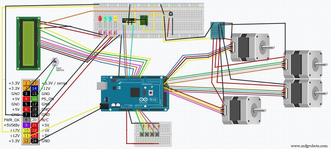
示意图
This is a complete Diagram of the system. It includes, ATX power supply, motors,LCD,LEDs, lights and controller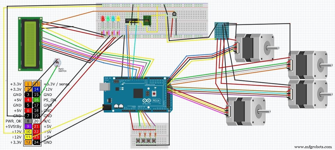
制造工艺