

用于 RC 模型和 Arduino 项目的 DIY Arduino RC 接收器
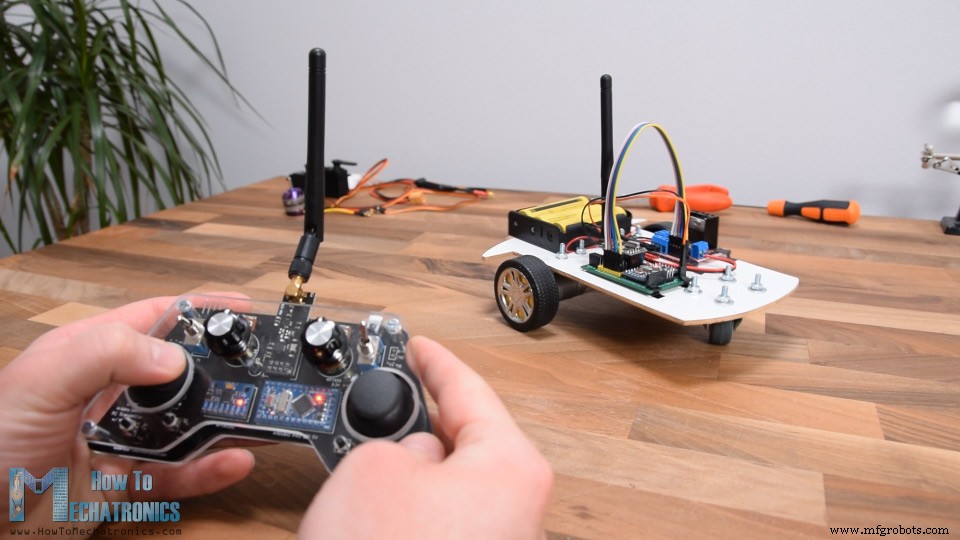
在本教程中,我们将学习如何制作基于 Arduino 的 RC 接收器。自从在我之前的一个视频中构建了我的 DIY Arduino RC 发射器后,我收到了你们的很多要求,为它制作一个专用的接收器,所以就在这里。
您可以观看以下视频或阅读下面的书面教程。
现在这两个设备可以轻松通信,我们可以用它们无线控制很多东西。我将通过几个例子来解释一切是如何工作的。在第一个示例中,我们将使用这个 Arduino RC 接收器来控制由两个直流电机组成的简单汽车。在第二个示例中,我将向您展示如何控制无刷电机和伺服系统,它们是许多商用遥控飞机、船只、汽车等中常见的组件。如果我们知道如何控制它们,我们可以使用我们自己定制的 Arduino 发射器轻松修改和控制许多 RC 模型。
作为第三个示例,我将向您展示我如何修改和使用这个基于 Arduino 的 RC 系统来控制商用 RC 汽车。
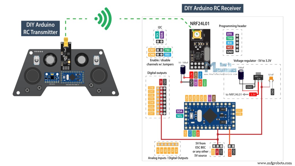
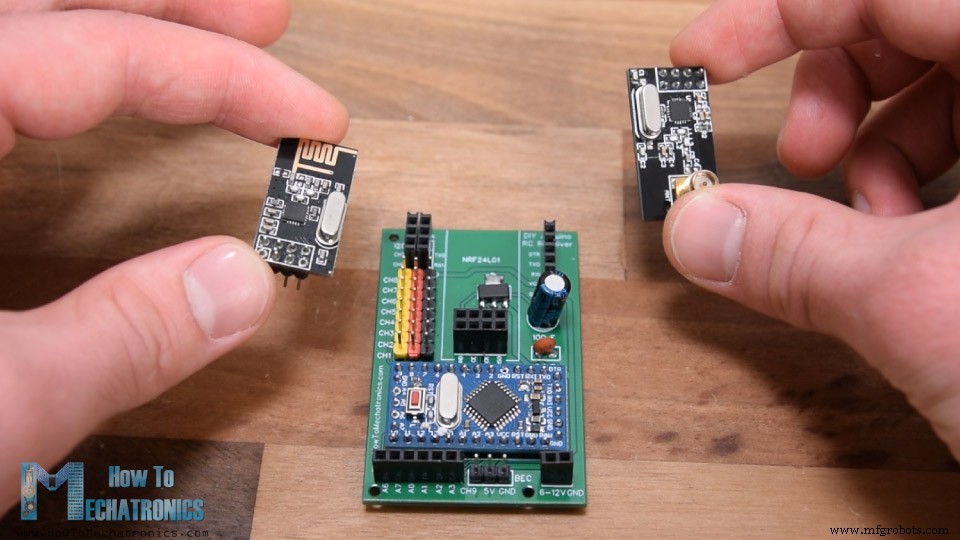
首先,让我们看一下这个系统的电路图。无线电通信基于NRF24L01收发模块。
发射器不断地从其控制器、操纵杆、按钮、电位器和拨动开关发送数据,我们通过接收器接收这些数据。有关此 Arduino 发射器如何工作的更多详细信息,您可以查看我的其他详细教程。
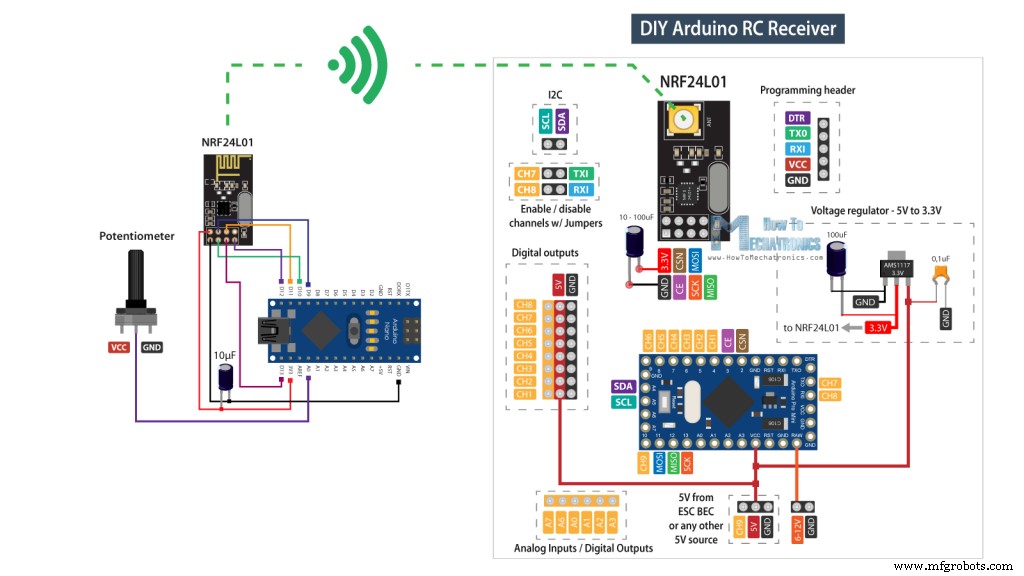
我们还可以在这里注意到,这个 RC 接收器不一定只与我构建的这个特定的发射器一起工作。它可以与任何其他由 Arduino 板和 NRF24L01 模块组成的类似设置一起使用。
尽管如此,这个 RC 接收器的大脑是一个 Arduino Pro Mini 板。对于供电,我们可以使用可以连接 5V 的 VCC 引脚,或者可以连接 6 至 12V 的 RAW 引脚。请注意,Arduino Pro Mini 有两个版本,就像我在这里使用的一个在 5V 下运行,另一个在 3.3V 下运行。另一方面,NRF24L01 模块的工作电压为 3.3V,因此我们需要一个稳压器。这次我使用的是 AMS1117 稳压器,它从 5V 到 12V 的输入输出 3.3V。
您可以从以下链接获取此 Arduino RC 接收器所需的组件:
为了与 Arduino 通信,NRF24L01 模块使用 SPI 协议,外加两个额外的数字引脚。这意味着我们剩下 9 个可用作输出通道的数字引脚,其中两个是 RX 和 TX 引脚。值得注意的是,当我们将草图上传到 Arduino 板时,这些引脚必须与任何东西断开连接,因此我可以通过单独的引脚接头连接或断开连接。实际上,我们也可以将模拟输入用作数字输出,所以虽然这个 Arduino 板很小,但我们有很多可用的输出或通道。
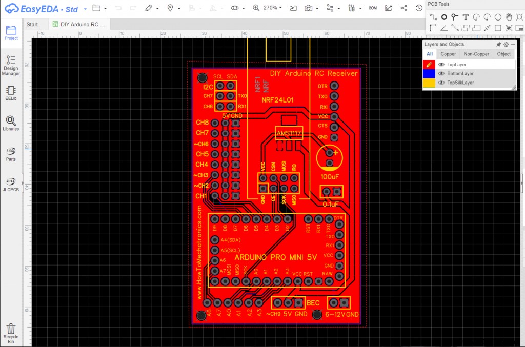
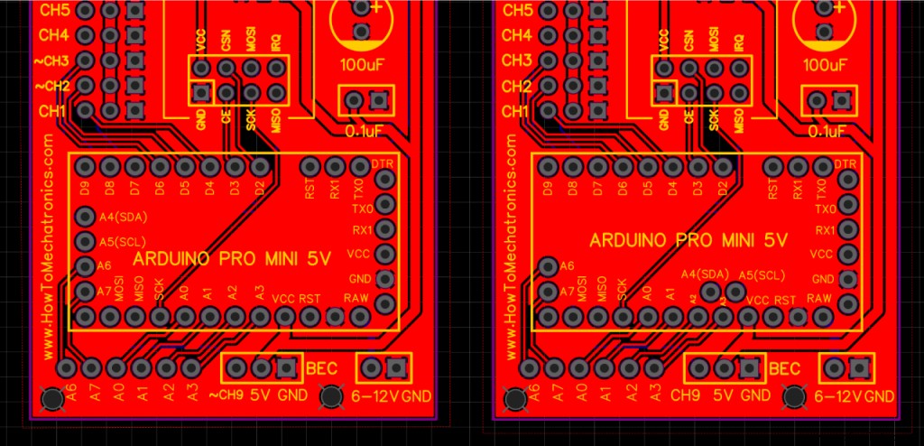
尽管如此,为了保持这个电路紧凑,我使用 EasyEDA 免费在线电路设计软件制作了一个定制的 PCB。在这里,我将 8 个通道安排在一个 5V 和一个接地轨旁边,因此我们可以直接将舵机和 ECS 连接到它们。通道号 9 位于一个单独的位置,靠近 Arduino 的 VCC 引脚,因此我们可以使用例如 ESC 为 Arduino 供电,其电池消除器电路功能提供 5V。当然,我们可以使用任何其他通道来达到这个目的,因为 VCC 引脚也连接到那些 5V 电源轨。
至于通道号 7 和 8,我们可以在这里看到这些排针是如何中断的。如果我们想使用它们,我们只需将两个引脚连接在一起。编程头位于右上角,100uF 电容用于稳压器和 NRF24L01 模块。在 PCB 的左下角,我放置了模拟引脚。
在这里我们还要注意一件事,那就是一些 Arduino Pro Mini 板可能有不同的引脚排列,因此我增加了一个版本的 PCB,以便您选择与您的 Arduino Pro Mini 板匹配的版本。
这是此 PCB 的项目文件的链接。所以一旦我完成了设计,我就生成了制造 PCB 所需的 Gerber 文件。
Gerber 文件:
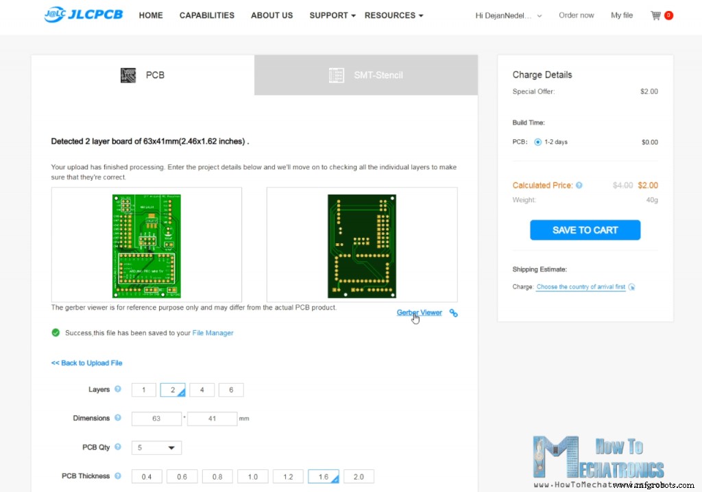
然后我从JLCPCB订购了PCB,这也是这个视频的赞助商。
在这里,我们可以简单地拖放 Gerber 文件,上传后,我们可以在 Gerber 查看器中查看我们的 PCB。如果一切正常,那么我们可以继续选择我们想要的 PCB 属性。就是这样,现在我们可以简单地以合理的价格订购我们的 PCB。请注意,如果这是您从 JLCPCB 订购的第一个订单,您只需 2 美元即可获得多达 5 个 PCB。
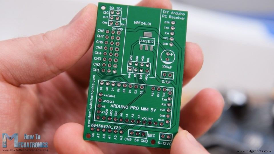
几天后,多氯联苯已经到货了。 PCB的质量很好,一切都与设计中的完全一样。
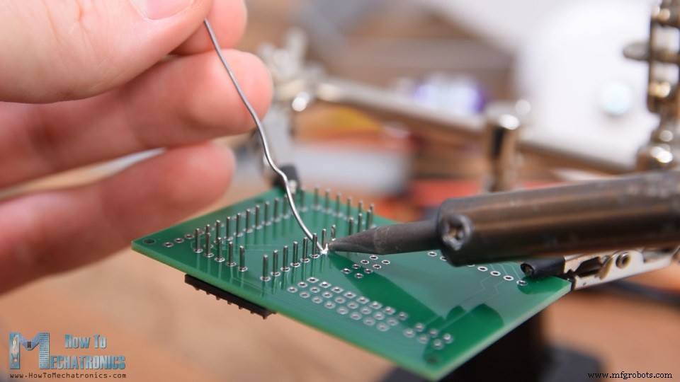
现在我们可以继续组装PCB了。首先,我们需要焊接 Arduino 板的排针。一种方便的方法是使用面包板将排针插入其中,这样电路板在焊接时将牢固地固定在原位。正如我之前所说,根据您的电路板,引脚可能会有所不同,因此在焊接时请记住这一点。
此外,我们需要留出一些接地引脚,因为它们下方的 PCB 上有一些走线。焊接 Arduino 板后,我将引脚上多余的长度剪掉。
接下来,我将所有其他排针放置到位。我们需要公头和母头排针,或者实际上取决于您选择使用什么排针。但是,数字通道最好使用公排针,因为伺服电机和 ESC 连接是母的,因此我们可以轻松连接它们。
稳压器是一种表面贴装元件,所以我在焊接时使用了一些 Blue-Tack 粘合剂将其固定到位。最后,将两个电容器焊接到位后,我们可以将 NRF24L01 模块连接到适当的排针。
根据应用或我们需要的范围,我们可以使用带有板载天线的普通模块,也可以使用我们可以连接更大天线的模块,并且可以在开放空间实现长达 700 米的无线通信.就是这样,我们的 Arduino RC 接收器现在已经准备就绪,我们可以将它用于任何我们想要的东西。
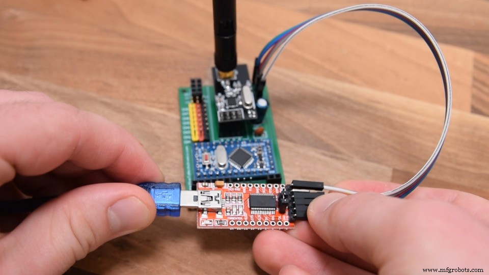
对接收器进行编程,或者将Arduino Pro Mini连接到电脑,我们可以使用USB转串口UART接口,可以连接到烧录头。
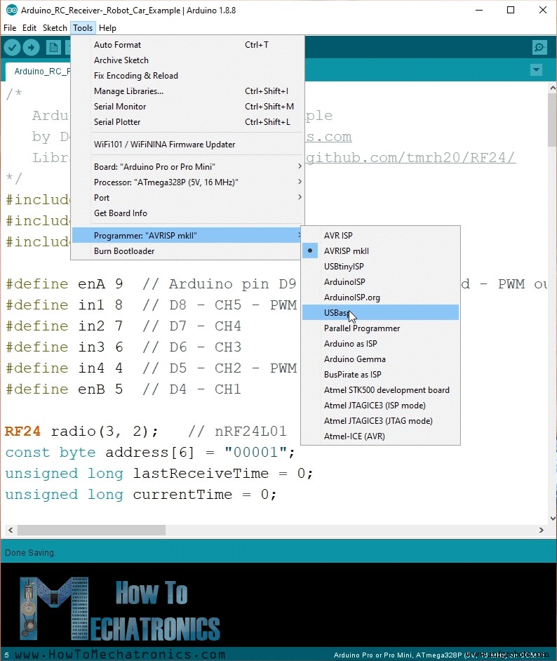
在Arduino IDE工具菜单中我们需要选择Arduino Pro或Pro Mini板,选择合适的处理器版本,选择端口,选择烧录方式为“USBasp”。
所以现在我们可以将代码上传到 Arduino。
好的,现在我们可以继续看第一个示例。
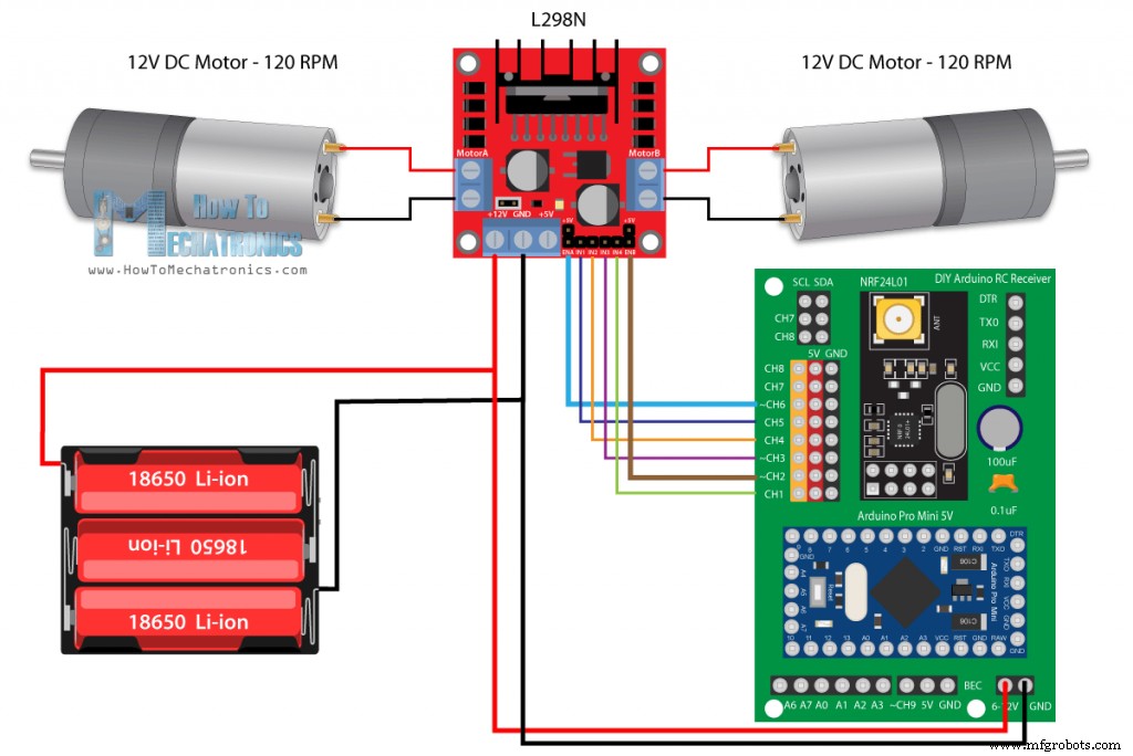
这是一辆由两个 12V 直流电机组成的简单汽车,在我之前的一些视频中,我已经向您展示了它的工作原理和制造方法。
另请参阅:L298N 电机驱动器 – Arduino 接口、工作原理、代码、原理图
这次我们将使用我们新的 Arduino RC 接收器来控制它。驱动直流电机,我们使用L298N电机驱动器,供电,我们使用3节锂离子电池,提供12V左右的电压。
您可以从以下链接获取本示例所需的组件:
所以,连接非常简单,来自电池的 12V 进入我们接收器上的 12V 引脚,驱动器的六个控制引脚进入 6 个通道。这里需要注意的是,为了能够控制电机的速度,我们需要向驱动器的 Enable A 和 Enable B 引脚提供 PWM 信号。在我们的接收器中,通道号 2、3、6 和 9 可以输出 PWM 信号,因此我在本例中将驱动器的 Enable 引脚连接到通道号 2 和 6。
现在让我们看一下Arduino代码。
说明: 因此,首先我们需要包含 SPI 和 RF24 库,定义一些引脚、无线电对象以及我们将存储来自发射器的传入数据的数据结构。在设置部分,我们需要定义引脚输出并开始无线电通信。有关它的工作原理以及这些行的作用的更多详细信息,您可以查看我的详细 NRF24L01 教程。
在循环部分,我们不断检查我们是否正在接收数据,如果接收到了,我们就会读取传入的数据。如果我们快速查看发送器代码,我们可以看到它发送给接收器的数据类型。它从其所有控制器、操纵杆、电位计和按钮中读取数据,并将这些数据作为单个数据包发送到接收器。
所以,一旦我们读取了这些数据,我们就可以用它做任何我们想做的事情。在这种情况下,我们将使用操纵杆 1 的 Y 轴值来控制油门,使用 X 轴值来控制转向。我将这些数据放入单独的油门和转向变量中。我们从操纵杆获得的值是从 0 到 255。因此,如果我们向下移动操纵杆,我们将适当地设置驾驶员控制销,以便汽车向后移动,并使用油门值来控制移动速度。相同的原则适用于向前、向左和向右行驶。同样,我已经有关于这辆车如何工作的详细教程,因此您可以查看它以获得更好的理解。在代码的底部,我们可以看到 resetData() 自定义函数,它将所有值重置为其初始默认值,以便在无线电通信丢失的情况下,汽车将当场移动。
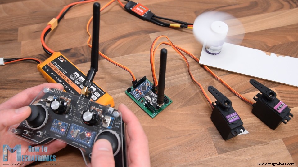
好的,现在我们可以继续第二个示例,使用这个 Arduino RC 接收器控制舵机和无刷电机。
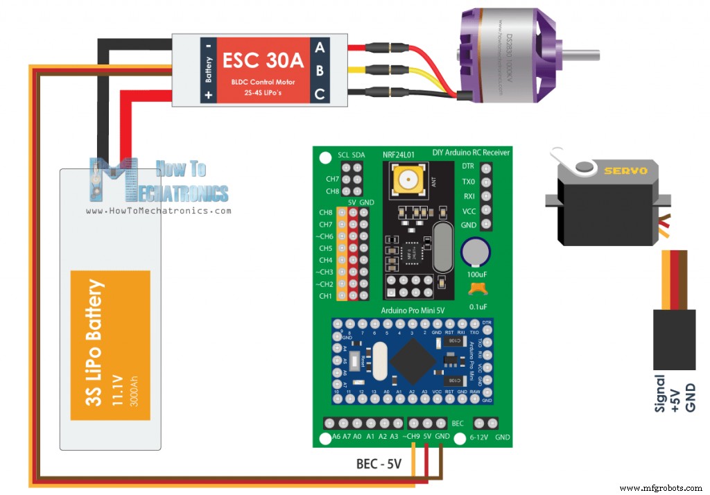
为了控制无刷电机,我们需要一个 ESC 或电子速度控制器。 Arduino 只需一个引脚即可与 ESC 通信。为了控制电调,Arduino 向电调发送特定的 PWM 信号,电调通过它控制电机速度。具有相同连接的 ESC 通过其电池消除电路功能提供 5V 电压,因此我们也可以使用它为接收器供电。
另请参阅:Arduino 无刷电机控制教程 |电调 |无刷直流
至于伺服电机,它们的连接类型与 ESC 相同,我们可以简单地将它们连接到任何可用的通道。
您可以从以下链接获取本示例所需的组件:
使用 ESC 控制舵机和无刷电机的输入信号几乎相同。他们使用特定的 50Hz PWM 信号,可以使用 Arduino Servo 库轻松生成。
注意: 在此设置中使用 MG996R 舵机时,它们可能会导致电路出现问题并烧毁 Arduino Pro Mini。这可能会消耗更高的电流,这可能会导致 5V 电压轨出现电压尖峰。 Arduino Pro Mini 应在 5V 引脚处处理高达 5.5v 的电压,但当这些尖峰发生时可能会烧毁 Arduino。我在测试电路时遇到了这个问题,评论部分的人也报告了同样的问题。解决这个问题的方法可能是在伺服系统上放置一个更大的去耦电容器,但我不太确定,也没有测试过。所以请注意这个问题。
另一方面,在示例中,我使用了另外两个没有烧毁 Arduino 的 MG996R 伺服系统,我猜是因为它们没有造成如此高的尖峰。我也用这个例子和 4 个较小的 S90 舵机一起使用,它没有任何问题。
另请参阅:伺服电机的工作原理 &如何使用 Arduino 控制舵机
因此,在接收到来自发送器的数据后,我们将 0 到 255 的值转换为 0 到 180 的值,以便使用 write() 函数控制舵机。同理,我们将控制 ESC 的数据转换为 1000 到 2000 的值。在这个例子中,我们从 1 号操纵杆的中间点控制这个 ESC,到向上的位置,因此我们从中间转换值, 127 到 255 转换为 1000 到 2000 的值。使用伺服库 writeMicroseconds() 函数,我们将 PWM 信号发送到 ESC,因此我们可以控制无刷电机的速度从最小到最大。
另请参阅:Arduino RC 飞机 | 100% 自制
所以,这就是我们可以控制遥控飞机、汽车、船只等的方法,因为它们通常使用这种类型的电机、舵机和无刷电机。
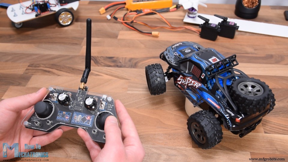
遥控车自带控制器,可以控制前轮左右移动,也可以前后移动。
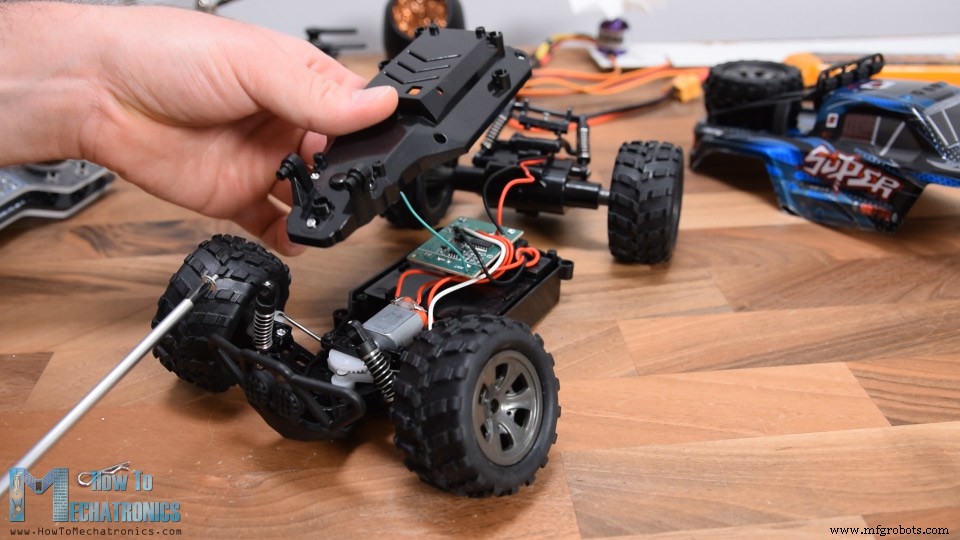
然而,由于它是一辆便宜的遥控车,控制是数字的,或者打开或关闭,以达到最大左右位置和最大速度。尽管如此,我还是拆开了这辆车,看看里面有什么,以及如何实现 Arduino RC 接收器来控制它。
一旦我发现电子元件,我注意到这两个电机实际上是简单的直流电机,工作电压为 5V。即使是控制转向有限运动的前电机也是一个简单的连续旋转直流电机。
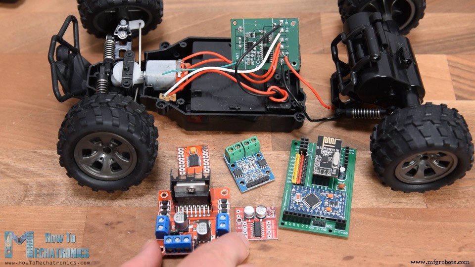
所以,显然,我们已经知道如何控制直流电机,所以用我们的 DIY Arduino 接收器替换这个电路板将非常容易。除了我们的接收器,我们只需要一个能够同时驱动两个电机的电机驱动器。为此目的有很多选择,甚至是我们在第一个示例中使用的 L298N 驱动器。
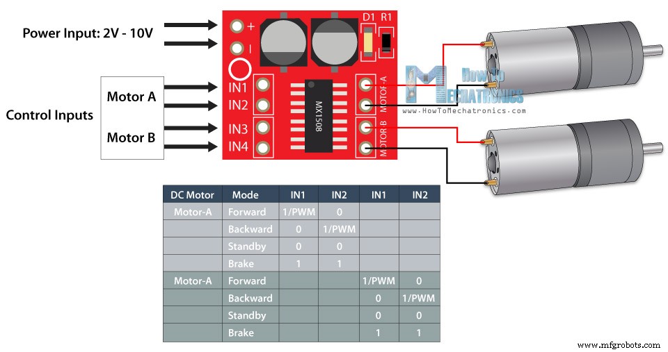
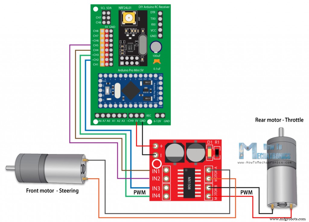
但是,对于这个应用来说,那个太大了,所以我选择了 MX1508 电机驱动器。这是一个简单的双直流电机驱动器,具有 H 桥和 PWM 控制。它有4个控制输入引脚,4个电机引脚,2个电源引脚。
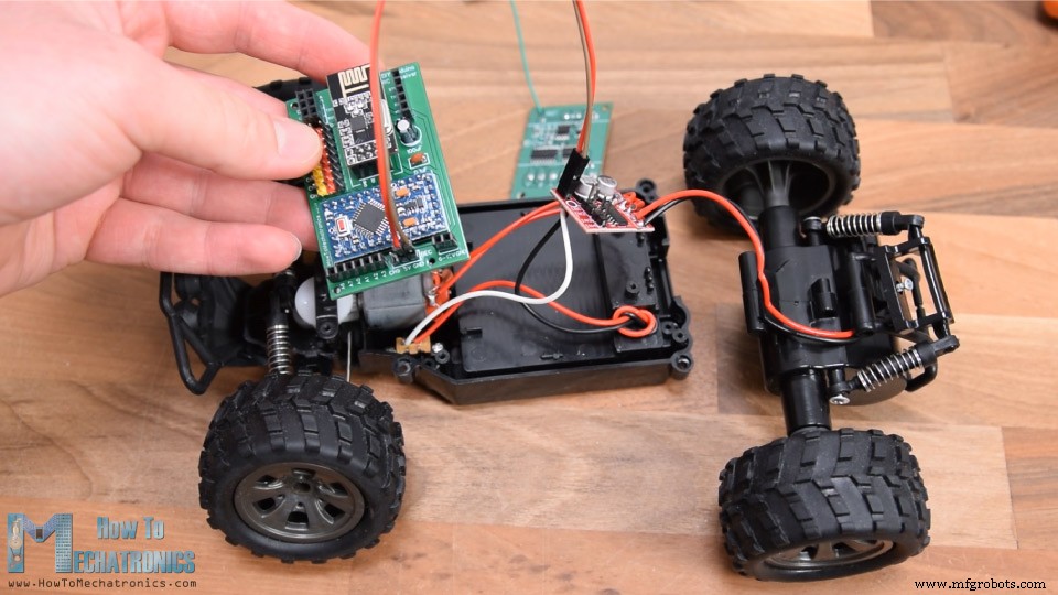
我从遥控车电路板上拆焊了电机连接并将它们焊接到驱动器上。在背面,我焊接了电源引脚,现在剩下的就是将此驱动器与接收器连接起来。这款遥控车的电源来自位于车底的 4.8V 镍镉电池。
因此,我使用跳线将这些引脚连接到 Arduino 的 VCC 引脚,并将驱动器的 4 个控制输入引脚连接到 4 个数字通道。正如我所说,这个驱动支持PWM控制,所以对于电机B,或者后置电机,我使用了2号和3号PWM通道。
您可以从以下链接获取本示例所需的组件:
这辆遥控车的代码和第一个例子很相似。
我们使用来自操纵杆的数据来控制遥控车的油门和转向。为了向后移动,我们使用模拟写入()函数将 PWM 信号发送到 Input3 引脚上的驱动器,同时我们将 input4 引脚保持为低电平。为了向前发展,我们采取相反的方式。如果操纵杆停留在中间,我们会向驾驶员发出刹车或停止电机的命令。转向电机使用相同的原理,不过这里我们不必使用analogWrite() 函数,因为我们不需要控制这个电机的速度。
将此草图上传到 Arduino 后,我不得不重新组装遥控车。我将小驱动器放在内部外壳中,并用螺钉固定其余部件。我将接收器与驱动器重新连接,并将其放在汽车外壳下方,该外壳有足够的位置可以放入接收器。
因此,我们不仅修改了这款遥控车,使用我们的 DIY 遥控发射器进行控制,而且还通过添加 PWM 控制对其进行了改进,现在我们还可以控制汽车的速度。如果您要修改的RC模型有舵机和无刷电机而不是直流电机,您可以按照第二个示例中的方法进行。
我希望你喜欢这个教程并学到了一些新东西。随时在下面的评论部分提出任何问题,不要忘记查看我收集的 Arduino 项目。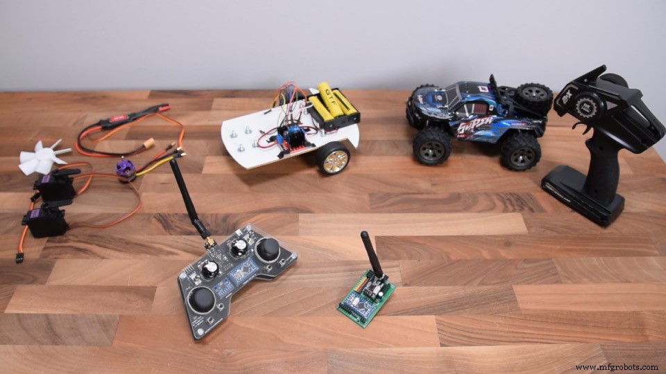
Arduino RC接收器电路图
PCB设计

PCB组装
示例 1 – Arduino 遥控车
/*
   Arduino RC Receiver - Car Example
   by Dejan, www.HowToMechatronics.com
   Library: TMRh20/RF24, https://github.com/tmrh20/RF24/
*/
#include <SPI.h>
#include <nRF24L01.h>
#include <RF24.h>

#define enA 9  // Arduino pin D9 - CH6 on PCB board - PWM output
#define in1 8  // D8 - CH5
#define in2 7  // D7 - CH4
#define in3 6  // D6 - CH3
#define in4 4  // D4 - CH1
#define enB 5  // D5 - CH2 - PWM output

RF24 radio(3, 2);   // nRF24L01 (CE, CSN)
const byte address[6] = "00001";
unsigned long lastReceiveTime = 0;
unsigned long currentTime = 0;

// Max size of this struct is 32 bytes
struct Data_Package {
  byte j1PotX;
  byte j1PotY;
  byte j1Button;
  byte j2PotX;
  byte j2PotY;
  byte j2Button;
  byte pot1;
  byte pot2;
  byte tSwitch1;
  byte tSwitch2;
  byte button1;
  byte button2;
  byte button3;
  byte button4;
};

Data_Package data; //Create a variable with the above structure

int  steering, throttle;
int motorSpeedA = 0;
int motorSpeedB = 0;

void setup() {
  pinMode(enA, OUTPUT);
  pinMode(enB, OUTPUT);
  pinMode(in1, OUTPUT);
  pinMode(in2, OUTPUT);
  pinMode(in3, OUTPUT);
  pinMode(in4, OUTPUT);
  //Serial.begin(9600);
  radio.begin();
  radio.openReadingPipe(0, address);
  radio.setAutoAck(false);
  radio.setDataRate(RF24_250KBPS);
  radio.setPALevel(RF24_PA_LOW);
  radio.startListening(); //  Set the module as receiver
  resetData();
}
void loop() {
  // Check whether we keep receving data, or we have a connection between the two modules
  currentTime = millis();
  if ( currentTime - lastReceiveTime > 1000 ) { // If current time is more then 1 second since we have recived the last data, that means we have lost connection
    resetData(); // If connection is lost, reset the data. It prevents unwanted behavior, for example if a drone jas a throttle up, if we lose connection it can keep flying away if we dont reset the function
  }
  // Check whether there is data to be received
  if (radio.available()) {
    radio.read(&data, sizeof(Data_Package)); // Read the whole data and store it into the 'data' structure
    lastReceiveTime = millis(); // At this moment we have received the data
  }

  // Parse the data from the Joystic 1 to the throttle and steering variables
  throttle = data.j1PotY;
  steering = data.j1PotX;

  // Throttle used for forward and backward control
  // Joystick values: 0 to 255; down = 0; middle = 127; up = 255
  if (throttle < 110) {
    // Set Motor A backward
    digitalWrite(in1, HIGH);
    digitalWrite(in2, LOW);
    // Set Motor B backward
    digitalWrite(in3, HIGH);
    digitalWrite(in4, LOW);
    // Convert the declining throttle readings for going backward from 110 to 0 into 0 to 255 value for the PWM signal for increasing the motor speed
    motorSpeedA = map(throttle, 110, 0, 0, 255);
    motorSpeedB = map(throttle, 110, 0, 0, 255);
  }
  else if (throttle > 140) {
    // Set Motor A forward
    digitalWrite(in1, LOW);
    digitalWrite(in2, HIGH);
    // Set Motor B forward
    digitalWrite(in3, LOW);
    digitalWrite(in4, HIGH);
    // Convert the increasing throttle readings for going forward from 140 to 255 into 0 to 255 value for the PWM signal for increasing the motor speed
    motorSpeedA = map(throttle, 140, 255, 0, 255);
    motorSpeedB = map(throttle, 140, 255, 0, 255);
  }
  // If joystick stays in middle the motors are not moving
  else {
    motorSpeedA = 0;
    motorSpeedB = 0;
  }
  // Steering used for left and right control
  if (steering < 110) {
    // Convert the declining steering readings from 140 to 255 into increasing 0 to 255 value
    int xMapped = map(steering, 110, 0, 0, 255);
    // Move to left - decrease left motor speed, increase right motor speed
    motorSpeedA = motorSpeedA - xMapped;
    motorSpeedB = motorSpeedB + xMapped;
    // Confine the range from 0 to 255
    if (motorSpeedA < 0) {
      motorSpeedA = 0;
    }
    if (motorSpeedB > 255) {
      motorSpeedB = 255;
    }
  }
  if (steering > 140) {
    // Convert the increasing steering readings from 110 to 0 into 0 to 255 value
    int xMapped = map(steering, 140, 255, 0, 255);
    // Move right - decrease right motor speed, increase left motor speed
    motorSpeedA = motorSpeedA + xMapped;
    motorSpeedB = motorSpeedB - xMapped;
    // Confine the range from 0 to 255
    if (motorSpeedA > 255) {
      motorSpeedA = 255;
    }
    if (motorSpeedB < 0) {
      motorSpeedB = 0;
    }
  }
  // Prevent buzzing at low speeds (Adjust according to your motors. My motors couldn't start moving if PWM value was below value of 70)
  if (motorSpeedA < 70) {
    motorSpeedA = 0;
  }
  if (motorSpeedB < 70) {
    motorSpeedB = 0;
  }
  analogWrite(enA, motorSpeedA); // Send PWM signal to motor A
  analogWrite(enB, motorSpeedB); // Send PWM signal to motor B
}
void resetData() {
  // Reset the values when there is no radio connection - Set initial default values
  data.j1PotX = 127;
  data.j1PotY = 127;
  data.j2PotX = 127;
  data.j2PotY = 127;
  data.j1Button = 1;
  data.j2Button = 1;
  data.pot1 = 1;
  data.pot2 = 1;
  data.tSwitch1 = 1;
  data.tSwitch2 = 1;
  data.button1 = 1;
  data.button2 = 1;
  data.button3 = 1;
  data.button4 = 1;
}Code language: Arduino (arduino)示例 2 - Arduino RC 接收器伺服和无刷电机控制
/*
  DIY RC Receiver - Servos and Brushless motors control
  by Dejan, www.HowToMechatronics.com
  Library: TMRh20/RF24, https://github.com/tmrh20/RF24/
*/
#include <SPI.h>
#include <nRF24L01.h>
#include <RF24.h>
#include <Servo.h>

RF24 radio(3, 2);   // nRF24L01 (CE, CSN)
const byte address[6] = "00001";
unsigned long lastReceiveTime = 0;
unsigned long currentTime = 0;
Servo esc;  // create servo object to control the ESC
Servo servo1;
Servo servo2;
int escValue, servo1Value, servo2Value;
// Max size of this struct is 32 bytes - NRF24L01 buffer limit
struct Data_Package {
  byte j1PotX;
  byte j1PotY;
  byte j1Button;
  byte j2PotX;
  byte j2PotY;
  byte j2Button;
  byte pot1;
  byte pot2;
  byte tSwitch1;
  byte tSwitch2;
  byte button1;
  byte button2;
  byte button3;
  byte button4;
};
Data_Package data; //Create a variable with the above structure
void setup() {
  Serial.begin(9600);
  radio.begin();
  radio.openReadingPipe(0, address);
  radio.setAutoAck(false);
  radio.setDataRate(RF24_250KBPS);
  radio.setPALevel(RF24_PA_LOW);
  radio.startListening(); //  Set the module as receiver
  resetData();
  esc.attach(10);   // Arduino digital pin D10 - CH9 on PCB board
  servo1.attach(4); // D4 - CH1
  servo2.attach(5); // D5 - CH2
}
void loop() {

  // Check whether we keep receving data, or we have a connection between the two modules
  currentTime = millis();
  if ( currentTime - lastReceiveTime > 1000 ) { // If current time is more then 1 second since we have recived the last data, that means we have lost connection
    resetData(); // If connection is lost, reset the data. It prevents unwanted behavior, for example if a drone jas a throttle up, if we lose connection it can keep flying away if we dont reset the function
  }

  // Check whether there is data to be received
  if (radio.available()) {
    radio.read(&data, sizeof(Data_Package)); // Read the whole data and store it into the 'data' structure
    lastReceiveTime = millis(); // At this moment we have received the data
  }

  // Controlling servos
  servo1Value = map(data.j2PotX, 0, 255, 0, 180); // Map the receiving value form 0 to 255 to 0 to 180(degrees), values used for controlling servos
  servo2Value = map(data.j2PotY, 0, 255, 0, 180);
  servo1.write(servo1Value);
  servo2.write(servo2Value);

  // Controlling brushless motor with ESC
  escValue = map(data.j1PotY, 127, 255, 1000, 2000); // Map the receiving value form 127 to 255 to  1000 to 2000, values used for controlling ESCs
  esc.writeMicroseconds(escValue); // Send the PWM control singal to the ESC

}
void resetData() {
  // Reset the values when there is no radio connection - Set initial default values
  data.j1PotX = 127;
  data.j1PotY = 127;
  data.j2PotX = 127;
  data.j2PotY = 127;
  data.j1Button = 1;
  data.j2Button = 1;
  data.pot1 = 1;
  data.pot2 = 1;
  data.tSwitch1 = 1;
  data.tSwitch2 = 1;
  data.button1 = 1;
  data.button2 = 1;
  data.button3 = 1;
  data.button4 = 1;
}Code language: Arduino (arduino)示例 3 – 遥控车模型控制
/*
   Arduino RC Receiver - RC Model control
   by Dejan , www.HowToMechatronics.com
   Library: TMRh20/RF24, https://github.com/tmrh20/RF24/
*/
#include <SPI.h>
#include <nRF24L01.h>
#include <RF24.h>

#define in3 5  // D5 - CH2 - PWM output
#define in4 6  // D6 - CH3 - PWM output
#define in1 7  // D7 - CH4
#define in2 8  // D8 - CH5


RF24 radio(3, 2);   // nRF24L01 (CE, CSN)
const byte address[6] = "00001";
unsigned long lastReceiveTime = 0;
unsigned long currentTime = 0;

// Max size of this struct is 32 bytes
struct Data_Package {
  byte j1PotX;
  byte j1PotY;
  byte j1Button;
  byte j2PotX;
  byte j2PotY;
  byte j2Button;
  byte pot1;
  byte pot2;
  byte tSwitch1;
  byte tSwitch2;
  byte button1;
  byte button2;
  byte button3;
  byte button4;
};

Data_Package data; //Create a variable with the above structure

int  steering, throttle;
int motorSpeedA = 0;
int motorSpeedB = 0;

void setup() {
  pinMode(in1, OUTPUT);
  pinMode(in2, OUTPUT);
  pinMode(in3, OUTPUT);
  pinMode(in4, OUTPUT);
  Serial.begin(9600);
  radio.begin();
  radio.openReadingPipe(0, address);
  radio.setAutoAck(false);
  radio.setDataRate(RF24_250KBPS);
  radio.setPALevel(RF24_PA_LOW);
  radio.startListening(); //  Set the module as receiver
  resetData();
}
void loop() {
  // Check whether we keep receving data, or we have a connection between the two modules
  currentTime = millis();
  if ( currentTime - lastReceiveTime > 1000 ) { // If current time is more then 1 second since we have recived the last data, that means we have lost connection
    resetData(); // If connection is lost, reset the data. It prevents unwanted behavior, for example if a drone jas a throttle up, if we lose connection it can keep flying away if we dont reset the function
  }
  // Check whether there is data to be received
  if (radio.available()) {
    radio.read(&data, sizeof(Data_Package)); // Read the whole data and store it into the 'data' structure
    lastReceiveTime = millis(); // At this moment we have received the data
  }
  // Parse the data from the Joystic 1 to the steering and throttle variables
  steering = data.j2PotX;
  throttle = data.j1PotY;


// Throttle used for forward and backward control
  if (throttle < 110) {
    // Convert the declining throttle readings for going backward from 110 to 0 into 0 to 255 value for the PWM signal for increasing the motor speed
    motorSpeedB = map(throttle, 110, 0, 0, 255);
    // Set Motor B backward
    analogWrite(in3, motorSpeedB);
    digitalWrite(in4, LOW);
  }
  else if (throttle > 140) {
    // Convert the increasing throttle readings for going forward from 140 to 255 into 0 to 255 value for the PWM signal for increasing the motor speed
    motorSpeedB = map(throttle, 140, 255, 0, 255);
    // Set Motor B forward
    digitalWrite(in3, LOW);
    analogWrite(in4, motorSpeedB);
  }
  // If joystick stays in middle the motors are not moving
  else {
    digitalWrite(in3, HIGH);
    digitalWrite(in4, HIGH);
  }

// steering used for left and right control
  if (steering < 110) {
    digitalWrite(in1, HIGH);
    digitalWrite(in2, LOW);
  }
  if (steering > 140) {
    digitalWrite(in1, LOW);
    digitalWrite(in2, HIGH);
  }
  // If joystick stays in middle the motors are not moving
  else {
    digitalWrite(in1, HIGH);
    digitalWrite(in2, HIGH);
  }
}
void resetData() {
  // Reset the values when there is no radio connection - Set initial default values
  data.j1PotX = 127;
  data.j1PotY = 127;
  data.j2PotX = 127;
  data.j2PotY = 127;
  data.j1Button = 1;
  data.j2Button = 1;
  data.pot1 = 1;
  data.pot2 = 1;
  data.tSwitch1 = 1;
  data.tSwitch2 = 1;
  data.button1 = 1;
  data.button2 = 1;
  data.button3 = 1;
  data.button4 = 1;
}Code language: Arduino (arduino)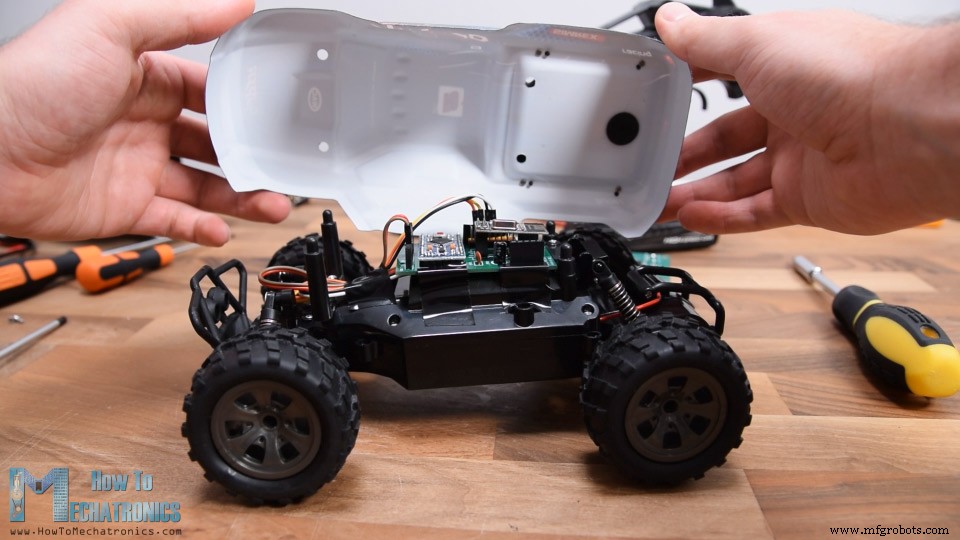
制造工艺