

DIY 自动售货机 - 基于 Arduino 的机电一体化项目
在这个项目中,我们将学习如何制作基于 Arduino 的 DIY 自动售货机。我将向您展示构建它的整个过程,从切割和组装 MDF 板开始,到将所有电子部件连接在一起并编写 Arduino 代码。
您可以观看以下视频或阅读下面的书面教程。
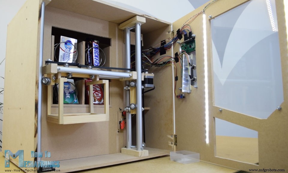
该自动售货机具有四个由四个连续旋转伺服电机控制的出料单元、一个由步进电机控制的搬运系统、一个液晶显示器、四个用于选择物品的按钮和一个硬币检测器。
您现在可能会想,物品载体对这台自动售货机没有那么有用,是的,您可能是对的。但我的想法是让这个项目更有趣或更复杂一点,这样你就可以学到更多新东西。我认为这个项目理念非常适合考虑将构建一个作为他们最后一年项目的电子或机电一体化学生,以及任何 Arduino 爱好者。
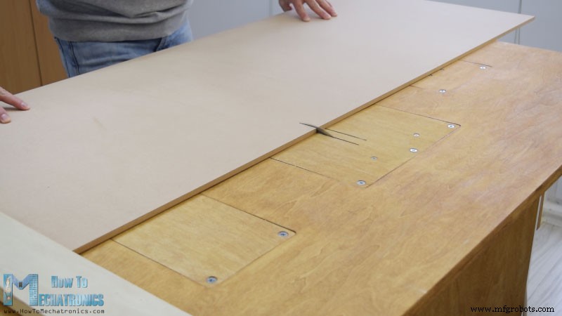
我首先将 8 毫米刻度的 MDF 板切割成合适的尺寸。
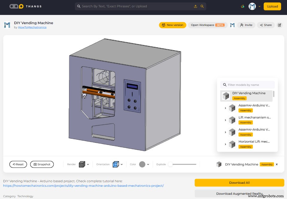
我之前制作了一个机器的 3D 模型,从那里我得到了所有的测量结果。
您可以找到并下载此 3D 模型,也可以在 Thangs 上的浏览器中进行探索。
为了切割 MDF,我使用了圆锯。实际上这是一个自制的工作台,配有圆锯、路由器和拼图,由我的搭档 Marija 制作,在她的 YouTube 频道 Creativity Hero 上有一个 DIY 视频。
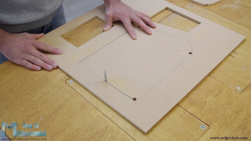
使用圆锯切割所有面板后,我继续使用倒置拼图在一些面板上制作开口。
实际上,如果您没有圆锯,甚至可以将拼图用于上一步。我还使用 Jigsaw 切割有多个切口的较小部分。但是请注意,这些都是危险机器,因此您在使用时需要非常小心。
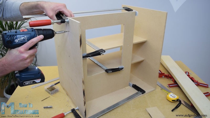
一旦我准备好所有 MDF 零件,我就开始使用一些木胶和螺丝来组装它们。为了固定面板,我使用了 90 度角夹。使用无绳电钻,我首先制作了导向孔,然后制作了反水槽并将 3 毫米螺钉拧入到位。我使用相同的方法组装所有面板,其中一些我还使用了一些 F 夹。
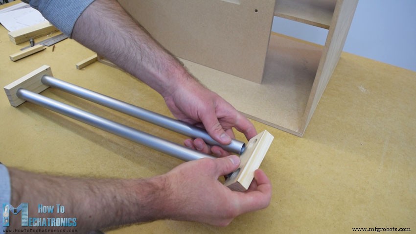
在组装的这一点上,我将继续制作轨道系统。为此,我使用了铝管,并使用金属手锯将它们切割成合适的尺寸。水平导轨的管子直径为 16 毫米,而垂直导轨的直径为 20 毫米。在一块 18 毫米的实心木板上,我使用 Forstner 钻头为管子制作了槽,然后将管子连接到它们上。
水平导轨由两根 27 厘米长的管子制成,而垂直导轨由三根 45 厘米长的管子制成。
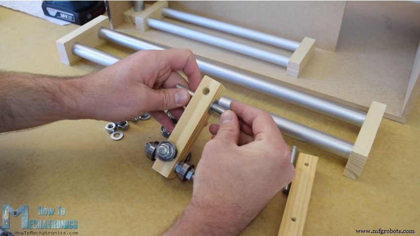
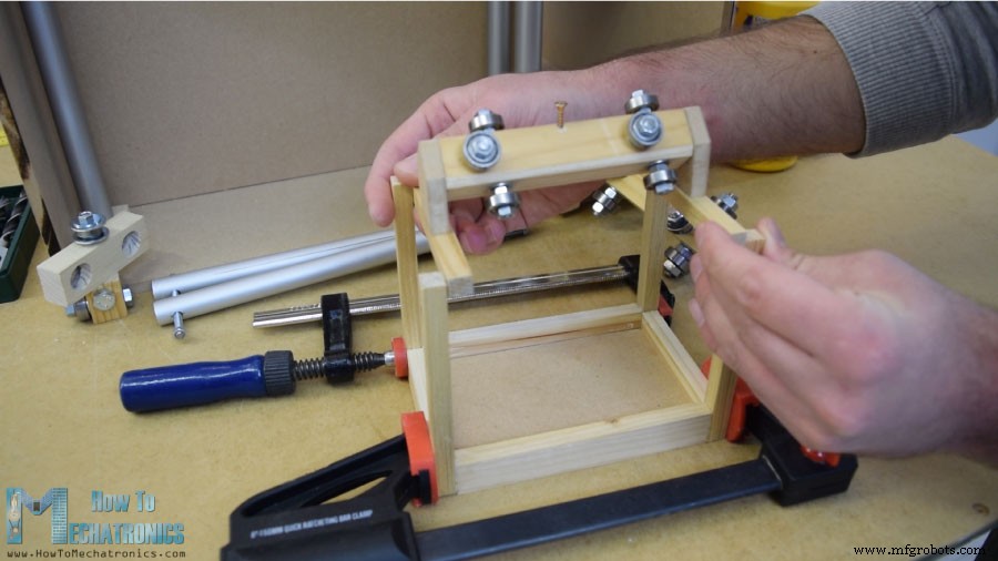
接下来是滑块,这是我制作它们的方法。我使用了 21 x 21 厘米的木板,在上面打了 8 毫米的孔。
然后我通过这些孔插入 8 毫米螺纹杆,并使用垫圈和螺母固定 22 毫米轴承。至于水平滑块,我使用了相同的方法,但轴承外径更小,为 16 毫米。
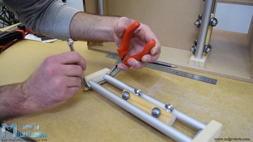
在我将滑块插入管轨之间后,我注意到它有点松动。为了解决这个问题,我不得不减少两条轨道之间的距离。所以首先我扩大了管槽,然后通过管子制作垂直槽,最后用一根螺纹杆将两个管轨固定得更近。在此之后,滑块不再松动并且它们工作正常。
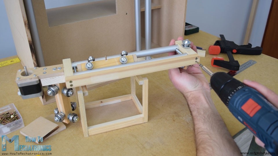
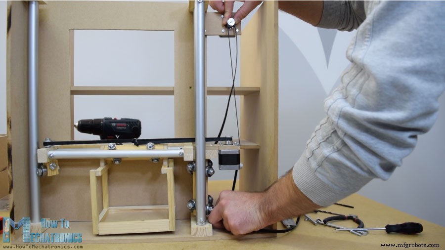
但是,此时我必须拆卸导轨才能添加其他元素。首先,我在导轨左侧添加了一个 5mm 螺栓,我将在其上连接一个用于水平同步带的滑轮,以及另外两个将在左侧垂直导轨上滑动的轴承。
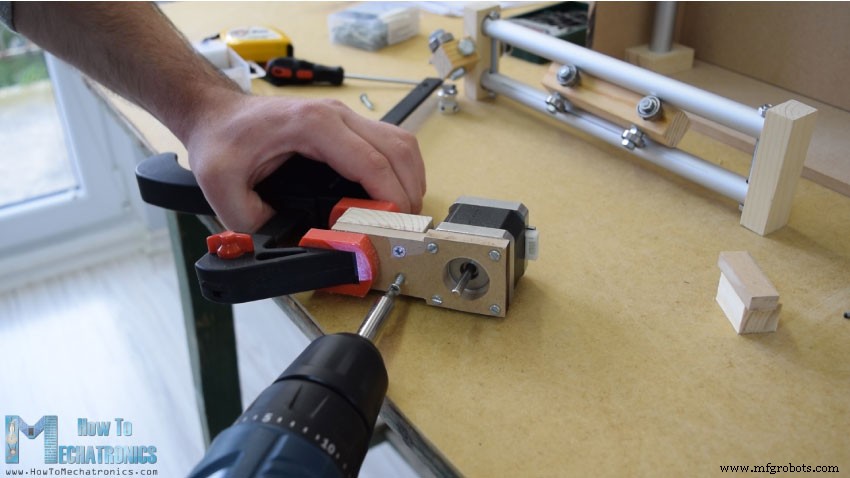
在导轨的另一侧,我必须安装步进电机以进行水平运动。首先,我将电机固定在 8 mm MDF 板上,然后在其上添加一块支撑木头,并将开槽部分固定在其上。最后,我用木胶和两个螺丝将整个组件连接到垂直滑块上。
接下来,我继续在水平滑块上添加容器。为此,我使用了一些小块木头,我用木胶将它们连接在一起。一旦我完成了这个,我就准备好组装铁路系统了。我在导轨槽中使用了一些环氧树脂,并在导轨侧面添加了一块额外的木板,以使整个导轨系统更加坚固。
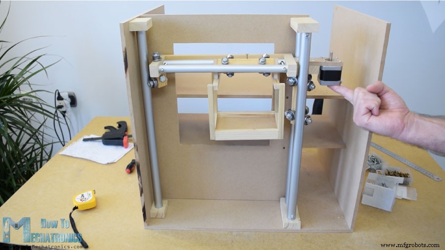
在下一步中,我将组件插入垂直导轨之间并将它们也固定到位。滑块和导轨系统的最终效果非常好。
我继续安装水平同步带。我测量了我需要的长度,把它剪成合适的尺寸,然后用一条拉链把它固定在滑块上。至于垂直滑块,我使用一块 MDF 和一些螺栓将步进电机安装在机器顶部。在底部,我安装了皮带轮并以类似的方式安装了正时皮带。
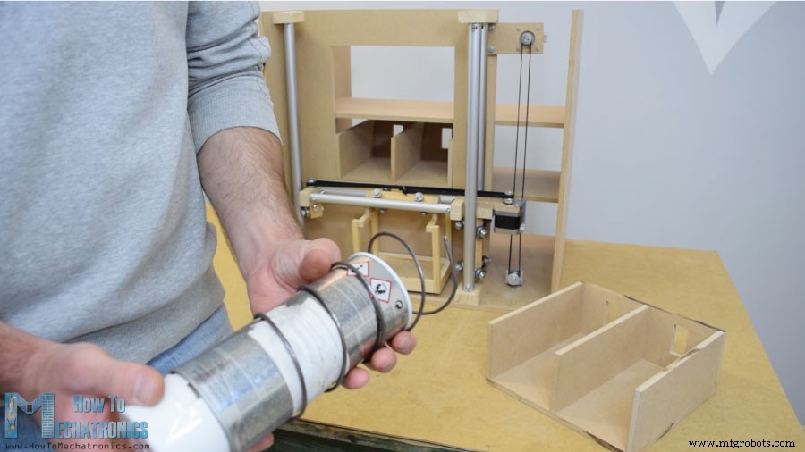
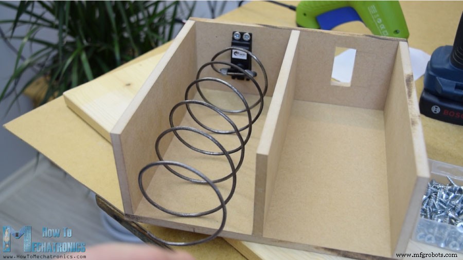
接下来,我转到物品排放单元。我用直径为 7 厘米的喷漆罐用 3 毫米刻度金属线制成了一个螺旋线圈。
之后我用胶枪把它固定在一个连续旋转的伺服电机上。
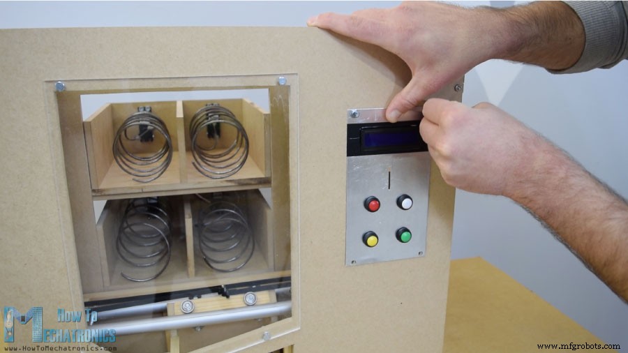
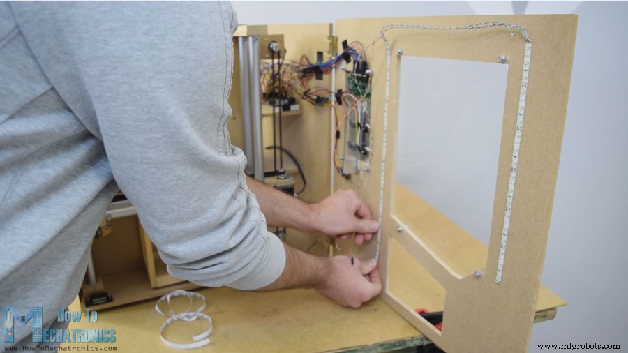
接下来是前门面板,我使用简单的铰链将其连接到自动售货机上,为了锁定它,我使用了磁性门锁。然后我用 5 毫米刻度的丙烯酸盖住前面的大开口,而对于右侧较小的开口,我使用了非常锡的铝板。在这里,我为按钮制作了 4 个孔,以及硬币和 LCD 显示屏的开口。我用钻头和钢锯来制作它们。将电子部件连接到铝板上后,我使用 5 毫米螺栓将其连接到前门板上。
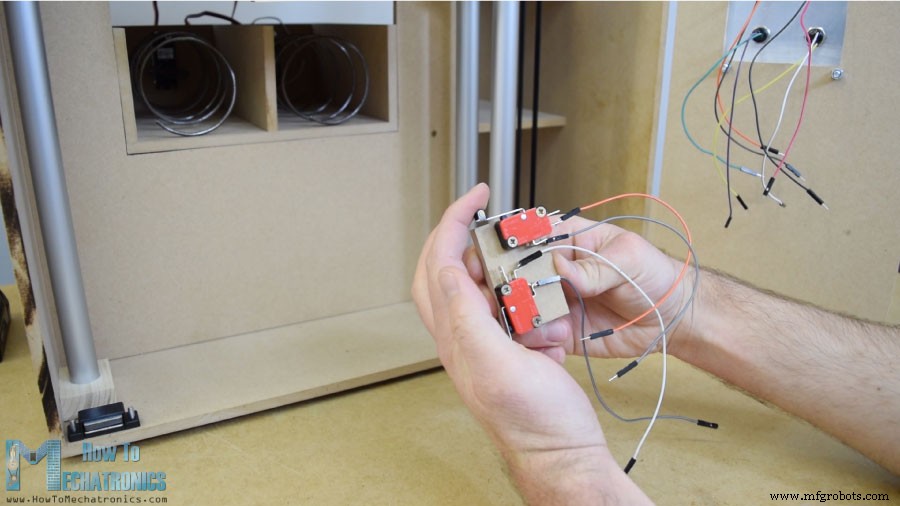
为了将载体定位到其起始位置,我安装了两个微动开关,对于硬币,我粘了一个导向器,它将引导硬币滑到机器底部。
硬币探测器是一个简单的红外接近传感器,所以当硬币靠近它时,传感器会给我们一个正反馈。
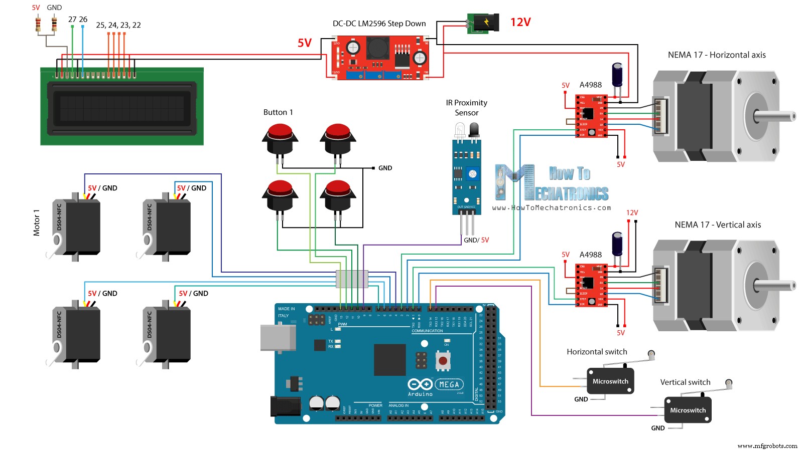
接下来是有趣的部分,将所有电子元件连接到 Arduino 板。这是这个 DIY 自动售货机项目的完整电路原理图。
所以我们需要12V电源,至少2安培。我们需要两个步进电机的 12V 电源,以及稍后我将安装在前门上的 LED 灯条。但是,对于所有其他组件,我们需要 5V,因此我使用降压转换器将 12V 降压至 5V。 DS04-NFC 连续旋转伺服电机由 5V 供电,并通过来自 Arduino 板的 PWM 信号进行控制,而步进电机则通过 A4988 驱动器进行控制。四个按钮和两个微动开关连接到地和 Arduino 数字引脚,因此使用 Arduino 板的内部上拉电阻我们可以很容易地检测到它们何时被按下。
您可以从以下链接获取本 Arduino 教程所需的组件:
我使用一些跳线连接了电子元件。这么多电线有点乱,但一切正常。最后,我在门板上安装了两个 LED 灯条,以照亮自动售货机的内部。
现在剩下的是对 Arduino 进行编程,这是我为这个项目编写的代码。下面是代码的说明。
首先我们需要包含 Servo 和 LiquidCrystal 库,定义 LCD 引脚、四个伺服电机、步进电机引脚、硬币探测器以及四个按钮和两个微动开关。
在设置部分,我们为上面提到的每个引脚设置引脚模式。我们可以注意到,对于按钮和微动开关引脚,我们激活了内部上拉电阻。这意味着这些引脚的逻辑电平会一直处于高电平,一旦我们按下它们,逻辑电平就会下降到低电平。
在我们进入主循环之前,我们还将载体设置到由两个微动开关定义的起始位置。因此,在 while 循环中,我们不断将载体移动到其起始位置,一旦按下两个微动开关,电机就会停止并移动到所需的起始位置。
在主程序中,首先在 LCD 上打印信息“Insert a coin”。然后我们陷入了while循环。一旦插入硬币并通过接近传感器附近,硬币检测器引脚的逻辑状态将下降到低电平,在这种情况下,我们将使用 break 语句退出 while 循环。
然后我们打印消息“选择您的项目”,然后我们陷入另一个 while 循环。
这个while循环等待我们按下四个按钮中的任何一个,一旦我们这样做了,我们就会退出并打印消息“Delivering”。
现在根据按下的按钮,我们在 switch 语句中执行一次案例。如果我们按下了第一个按钮,载体将使用定制的“moveUp()”函数开始向上移动。
如果我们看一下这个函数,我们会发现它只是将步进电机设置为沿特定方向移动,并将我们输入的步数作为参数。
我们可以在这里注意到,我将 A4988 步进驱动器设置为以四分之一步分辨率工作,并且通过一些品尝我得出结论,我需要 4900 步才能使载体到达较高位置。以类似的方式,我们将载体向左移动,直到它到达位置编号 1。
紧接着我们将连续旋转电机旋转 950 毫秒,使螺旋线圈完成一个完整的循环。
请注意,这些值有时会有所不同,具体取决于电机本身。使用 moveRight() 和 moveDown() 自定义函数,我们将载体带回起始位置。同样的方法,我们可以排放任何四个项目。
最后我们只打印消息“项目已交付”。
就这么简单,我希望你喜欢这个视频并学到了一些新东西。随时在下面的评论部分提出任何问题,并查看我的 Arduino 项目集合。概览
构建自动售货机
轨道系统
放电单位
前面板
电路原理图
Arduino 代码
/*     DIY Vending Machine - Arduino based Mechatronics Project

    by Dejan Nedelkovski, www.HowToMechatronics.com

*/

#include <LiquidCrystal.h> // includes the LiquidCrystal Library
#include <Servo.h>

LiquidCrystal lcd(27, 26, 25, 24, 23, 22); // Creates an LC object. Parameters: (rs, enable, d4, d5, d6, d7)
Servo servo1, servo2, servo3, servo4;   // DS04-NFC motors

// Stepper motors pins
#define dirPinVertical 0
#define stepPinVertical 1
#define dirPinHorizontal 2
#define stepPinHorizontal 3

#define coinDetector 9

#define button1 13
#define button2 12
#define button3 11
#define button4 10

#define microSwitchV 15
#define microSwitchH 14

int buttonPressed;

void setup() {
  lcd.begin(16, 2); // Initializes the interface to the LCD screen, and specifies the dimensions (width and height) of the display

  servo1.attach(4);
  servo2.attach(5);
  servo3.attach(6);
  servo4.attach(7);

  pinMode(dirPinVertical, OUTPUT);
  pinMode(stepPinVertical, OUTPUT);
  pinMode(dirPinHorizontal, OUTPUT);
  pinMode(stepPinHorizontal, OUTPUT);

  pinMode(coinDetector, INPUT);

  // Activating the digital pins pull up resistors
  pinMode(button1, INPUT_PULLUP);
  pinMode(button2, INPUT_PULLUP);
  pinMode(button3, INPUT_PULLUP);
  pinMode(button4, INPUT_PULLUP);

  pinMode(microSwitchV, INPUT_PULLUP);
  pinMode(microSwitchH, INPUT_PULLUP);

  // Vertical starting position
  digitalWrite(dirPinVertical, HIGH); // Set the stepper to move in a particular direction
  while (true) {
    if (digitalRead(microSwitchV) == LOW) { // If the micro switch is pressed, move the platfor a little bit up and exit the while loop
      moveUp(70);
      break;
    }
    // Move the carrier up until the micro switch is pressed
    digitalWrite(stepPinVertical, HIGH);
    delayMicroseconds(300);
    digitalWrite(stepPinVertical, LOW);
    delayMicroseconds(300);
  }
  // Horizontal starting position
  digitalWrite(dirPinHorizontal, LOW);
  while (true) {
    if (digitalRead(microSwitchH) == LOW) {
      moveLeft(350);
      break;
    }
    digitalWrite(stepPinHorizontal, HIGH);
    delayMicroseconds(300);
    digitalWrite(stepPinHorizontal, LOW);
    delayMicroseconds(300);
  }
}
void loop() {
  // Print "Insert a coin!" on the LCD
  lcd.clear();
  lcd.setCursor(0, 0);
  lcd.print("Insert a coin!");

  // Wait until a coin is detected
  while (true) {
    if (digitalRead(coinDetector) == LOW) { // If a coin is detected, exit the from the while loop
      break;
    }
  }

  delay(10);
  lcd.clear();
  lcd.setCursor(0, 0);
  lcd.print("Select your item");
  lcd.setCursor(0, 1);
  lcd.print(" 1, 2, 3 or 4?");

  // Wait until a button is pressed
  while (true) {
    if (digitalRead(button1) == LOW) {
      buttonPressed = 1;
      break;
    }
    if (digitalRead(button2) == LOW) {
      buttonPressed = 2;
      break;
    }
    if (digitalRead(button3) == LOW) {
      buttonPressed = 3;
      break;
    }
    if (digitalRead(button4) == LOW) {
      buttonPressed = 4;
      break;
    }
  }

  // Print "Delivering..."
  lcd.clear();
  lcd.setCursor(0, 0);
  lcd.print("Delivering...");

  // Depending on the pressed button, move the carrier to that position and discharge the selected item
  switch (buttonPressed) {
    case 1:
      // Move the container to location 1
      moveUp(4900); // Move up 4900 steps (Note: the stepper motor is set in Quarter set resolution)
      delay(200);
      moveLeft(1700); // Move left 1700 steps
      delay(300);
      // Rotate the helical coil, discharge the selected item
      servo1.writeMicroseconds(2000); // rotate
      delay(950);
      servo1.writeMicroseconds(1500);  // stop
      delay(500);
      // Move the container back to starting position
      moveRight(1700);
      delay(200);
      moveDown(4900);
      break;

     case 2:
      // Move the container to location 2
      moveUp(4900);
      delay(200);
      // Rotate the helix, push the selected item
      servo2.writeMicroseconds(2000); // rotate
      delay(950);
      servo2.writeMicroseconds(1500);  // stop
      delay(500);
      moveDown(4900);
      break;

      case 3:
      // Move the container to location 3
      moveUp(2200);
      delay(200);
      moveLeft(1700);
      delay(300);
      // Rotate the helix, push the selected item
      servo3.writeMicroseconds(2000); // rotate
      delay(950);
      servo3.writeMicroseconds(1500);  // stop
      delay(500);
      // Move the container back to starting position
      moveRight(1700);
      delay(200);
      moveDown(2200);
      break;

      case 4:
      // Move the container to location 4
      moveUp(2200); // Move verticaly 4800 steps
      delay(200);
      // Rotate the helix, push the selected item
      servo4.writeMicroseconds(2000); // rotate
      delay(950);
      servo4.writeMicroseconds(1500);  // stop
      delay(500);
      moveDown(2200);
      break;
  }

  lcd.clear(); // Clears the display
  lcd.setCursor(0, 0);
  lcd.print("Item delivered!"); // Prints on the LCD
  delay(2000);
}

// == Custom functions ==

void moveUp (int steps) {
  digitalWrite(dirPinVertical, LOW);
  for (int x = 0; x < steps; x++) {
    digitalWrite(stepPinVertical, HIGH);
    delayMicroseconds(300);
    digitalWrite(stepPinVertical, LOW);
    delayMicroseconds(300);
  }
}
void moveDown (int steps) {
  digitalWrite(dirPinVertical, HIGH);
  for (int x = 0; x < steps; x++) {
    digitalWrite(stepPinVertical, HIGH);
    delayMicroseconds(300);
    digitalWrite(stepPinVertical, LOW);
    delayMicroseconds(300);
  }
}
void moveLeft (int steps) {
  digitalWrite(dirPinHorizontal, HIGH);
  for (int x = 0; x < steps; x++) {
    digitalWrite(stepPinHorizontal, HIGH);
    delayMicroseconds(300);
    digitalWrite(stepPinHorizontal, LOW);
    delayMicroseconds(300);
  }
}
void moveRight (int steps) {
  digitalWrite(dirPinHorizontal, LOW);
  for (int x = 0; x < steps; x++) {
    digitalWrite(stepPinHorizontal, HIGH);
    delayMicroseconds(300);
    digitalWrite(stepPinHorizontal, LOW);
    delayMicroseconds(300);
  }
}Code language: Arduino (arduino)
源码说明
// Vertical starting position
  digitalWrite(dirPinVertical, HIGH); // Set the stepper to move in a particular direction
  while (true) {
    if (digitalRead(microSwitchV) == LOW) { // If the micro switch is pressed, move the platfor a little bit up and exit the while loop
      moveUp(70);
      break;
    }
    // Move the carrier up until the micro switch is pressed
    digitalWrite(stepPinVertical, HIGH);
    delayMicroseconds(300);
    digitalWrite(stepPinVertical, LOW);
    delayMicroseconds(300);
  }
  // Horizontal starting position
  digitalWrite(dirPinHorizontal, LOW);
  while (true) {
    if (digitalRead(microSwitchH) == LOW) {
      moveLeft(350);
      break;
    }
    digitalWrite(stepPinHorizontal, HIGH);
    delayMicroseconds(300);
    digitalWrite(stepPinHorizontal, LOW);
    delayMicroseconds(300);
}Code language: Arduino (arduino)// Wait until a coin is detected
while (true) {
if (digitalRead(coinDetector) == LOW) { // If a coin is detected, exit the from the while loop
break;
}
}Code language: Arduino (arduino)// Wait until a button is pressed
while (true) {
if (digitalRead(button1) == LOW) {
buttonPressed = 1;
break;
}
if (digitalRead(button2) == LOW) {
buttonPressed = 2;
break;
}
if (digitalRead(button3) == LOW) {
buttonPressed = 3;
break;
}
if (digitalRead(button4) == LOW) {
buttonPressed = 4;
break;
}
}Code language: Arduino (arduino)switch (buttonPressed) {
case 1:
// Move the container to location 1
moveUp(4900); // Move up 4900 steps (Note: the stepper motor is set in Quarter set resolution)
delay(200);
moveLeft(1700); // Move left 1700 steps
delay(300);
// Rotate the helical coil, discharge the selected item
servo1.writeMicroseconds(2000); // rotate
delay(950);
servo1.writeMicroseconds(1500); // stop
delay(500);
// Move the container back to starting position
moveRight(1700);
delay(200);
moveDown(4900);
break;
}Code language: Arduino (arduino)void moveUp (int steps) {
digitalWrite(dirPinVertical, LOW);
for (int x = 0; x < steps; x++) {
digitalWrite(stepPinVertical, HIGH);
delayMicroseconds(300);
digitalWrite(stepPinVertical, LOW);
delayMicroseconds(300);
}
}Code language: Arduino (arduino)// Rotate the helical coil, discharge the selected item
servo1.writeMicroseconds(2000); // rotate
delay(950);
servo1.writeMicroseconds(1500); // stopCode language: Arduino (arduino)
制造工艺