

光学显微镜
光学显微镜
显微镜研究放大物体的图像,这些物体太小而不能被肉眼正确看到。显微镜通过利用待观察样品发射、吸收、透射或反射的辐射(图 1)来完成其任务。辐射的性质指定了显微镜的类型,例如光学显微镜、电子显微镜、X 射线显微镜或声学显微镜等。电磁光谱的可见部分是光学显微镜使用的辐射类型。光学显微镜是通过光学显微镜对材料进行微观检查。
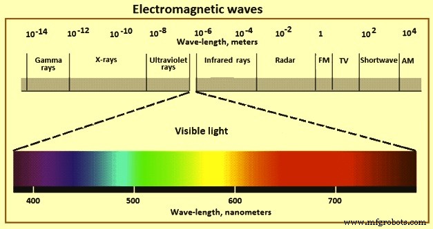
图 1 电磁波
古代使用粗放大镜,但现代显微镜的发展始于 17 世纪。尽管第一台复合显微镜是由 Hans 和 Zacharias Janssen 于 1595 年制造的,但 Antoni van Leeuwenhoek (1632–1723) 设法制造出如此出色的镜头,在他们非常简单的显微镜中实现了 300 倍左右的惊人放大倍率。由于 1670 年左右科学家罗伯特·胡克的建议,伦敦的仪器制造商克里斯托弗·科克(Christopher Cock)制造了一台非常成功的复合显微镜。使用这个仪器,胡克能够观察细胞。胡克显微镜堪称现代仪器之父。
光学显微镜,通常被称为“光学显微镜”,是一种使用可见光(图 1)和透镜系统放大小样本图像的显微镜。光学显微镜是最古老、最简单的显微镜。尽管复杂的电子金相仪器不断发展,但它是研究微观结构的非常重要的仪器。精密的“扫描电子显微镜”(SEM)和“透射电子显微镜”(TEM)也是非常宝贵的仪器。但它们应与光学显微镜结合使用,而不是作为替代品。
所有微观结构的检查都从使用光学显微镜开始,从低放大倍数(例如 100 倍)开始,然后逐渐提高放大倍率,以有效地评估微观结构的基本特征。大多数微结构可以用光学显微镜观察并根据其特征进行识别。可以通过观察它们相对于基体的硬度、它们的自然颜色、它们对偏振光的响应以及它们对选择性蚀刻剂的响应来帮助识别有问题的或未知的成分。这些观察结果与关于被检查材料的物理冶金学的已知细节进行了比较。如果仍有疑问或结构过于精细而无法观察,则需要实施更复杂的技术。
光学显微镜可用于检查抛光或蚀刻的金相样品。某些成分在抛光后更容易观察到,因为它们不会被蚀刻细节遮盖。夹杂物、氮化物、某些碳化物和金属间相可以很容易地在没有蚀刻的情况下观察到。除夹杂物外,如果在最终抛光过程中引入一些浮雕,则可以更容易地检查其他相。样品应经过充分准备,以确保对微观结构进行正确观察和解释,而不会因伪影而导致并发症。对偏振光有反应的样品,例如具有非立方晶体结构的材料,通常在不蚀刻的情况下进行检查。然而,在大多数情况下,要进行蚀刻以观察微观结构。通常首先使用通用蚀刻剂来揭示晶粒结构和存在的相,然后使用选择性蚀刻剂来攻击或着色特定感兴趣的相。选择性蚀刻剂广泛用于定量金相学,特别是使用自动化设备进行时。在任何一种情况下,都应仔细进行蚀刻以清晰地显示微观结构。
显微镜使用非常短焦距的物镜来形成大大放大的图像。然后使用用作简单放大镜的短焦距目镜查看此图像。光学显微镜的基本成像概念和结构如图2所示。显微镜的光学系统主要包括物镜和目镜。物镜的目的是放大物体,以便用户可以清楚地观察到它。在观察过程中,将样品放置在物空间中靠近物镜焦平面的位置,首先在中间平面上生成样品的放大实像。中间平面位于目镜的焦平面上,因此目镜起到放大镜的作用,进一步放大投影在中间像平面上的图像。最后,为观察者提供了一个放大的、虚拟的、倒置的图像。
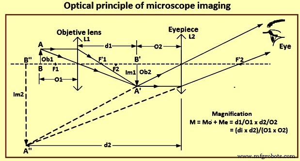
图2显微镜成像的光学原理
光学显微镜产生物体上不同点的可分离图像的能力是有限的。镜头的分辨能力是这种能力的定量衡量标准。接近分辨率极限的点不能被区分为单独的点。 Ernst Abbe 在 1873 年首先确定了两个相邻点之间的最小距离 d 的值,从而使它们可以被视为由等式“d =l/2n sin A”隔开,其中“l”是光的波长,“A”是镜头孔径角的二分之一,“n”是物体和镜头之间的介质的折射率。
目前,可以由物镜解决的两个物点的最小线性间隔由方程式'd =1.22(l / 2NA)'给出的瑞利标准固定,其中'l'是光的波长,并且“NA”是物镜的数值孔径。阿贝准则和瑞利准则非常相似,都是与成像介质相关的数值孔径 NA =n sin A。 sinA 的最大值为 1(A =90 度),因此理论最大数值孔径为空气中的物镜 (n =1) 是 NA =1。由于高 NA 是高分辨率的基本要求,因此开发了浸没式光学器件。样品可以通过具有不同折射率的浸没介质(如水(n =1.33)、甘油(n =1.47)或油(n =1.52))在距物镜很近的距离处成像。
对于设计良好的显微镜,空间分辨率主要由物镜决定。虽然目镜也可以放大图像,但它不能提高显微镜的分辨能力。光学显微镜的空间分辨率由瑞利方程 Ro =0 给出。 62 l/n sin A,其中'Ro'是最小可分辨距离,'l'是光的波长,'n'是透镜和物体之间的介质的折射率,'A'是1 -镜头角孔径的一半,n sinA 是物镜的数值孔径。
基于上述公式,并考虑到实际限制,即(i)使用波长在 390 nm(纳米)和 760 nm 之间的可见光,(ii)半角为 70 度至 75 度的最大可达孔径度,以及(iii)使用水或油浸泡方法以增加折射率的要求,常规光学显微镜的分辨率不能超过200 nm。
光学显微镜和显微镜的简化光波路如图3所示。现代光学显微镜能够将物体放大1500倍,空间分辨率限制在200纳米。光学显微镜可以使用各种标准分为许多不同的类型。例如,基于照明方式,显微镜有透射型和反射型。在透射显微镜中,光线穿过透明物体。在反射式显微镜中,安装在显微透镜顶部的光源照亮不透明物体,反射光被透镜收集。显微镜还可以根据观察方式来区分,包括明视野显微镜、暗视野显微镜、相差显微镜、偏光显微镜、干涉显微镜、荧光显微镜等。
每个显微镜都可以使用透射或反射方法。明场显微镜是所有显微镜中最流行和使用最广泛的。使用这种显微镜,一些被观察物体的透射(或吸收)比和反射比会随着工作环境的变化而变化。这些物体的振幅随光照强度的变化而变化。只有当照明光的相位发生变化时,才能看到无色透明物体。由于明场显微镜不能改变光的相位,使用这种显微镜是看不到无色透明样品的。
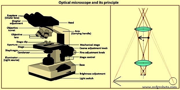
图3光学显微镜及其原理
显微镜组件
光学显微镜的成本和功能差异很大。反射光用于研究金属。透射光显微镜用于研究矿物和聚合物,也可以使用反射光进行检查。光学显微镜也分为“直立式”或“倒立式”。这些术语是指观察期间样品抛光平面的方向。由于每种配置都有一定的优缺点,因此选择基于个人喜好。最简单的光学显微镜是台式(通常是直立的)。根据支架的刚性,某些显微镜可以添加摄影功能。
适用于观察和光学显微镜的不同类型的显微镜可供选择。这些可以是相当简单的单元或具有各种照明模式、光源、微硬度附件、热台等的全尺寸研究显微镜。光学显微镜的基本组成如下图所示。
照明 系统 – 有多种用于光学显微镜的光源可供选择。主要用于台式显微镜的低压钨丝灯具有足够的观察强度,但不适用于摄影。改变灯泡的电流可以控制光强度。曾经在显微镜上常见的碳弧照明系统已被电弧或灯丝光源所取代。氙弧光源因其高强度和日光色特性而流行。然而,光强度只能通过使用中性密度滤光片来调整。卤钨灯丝灯也因其高强度和高色温而被广泛使用。可以通过改变电流或使用中性密度滤光片来控制光强度。其他光源,如锆弧灯、钠弧灯、石英碘灯或汞蒸气灯,则不太常见。
冷凝器 – 一个无球面像差和彗差的可调透镜放置在光源前面,以将光线聚焦在光路中所需的点。视场光阑放置在该镜头的前面,以最大限度地减少显微镜内的内部眩光和反射。视场光阑被停止到视场的边缘。第二个可调光圈光阑,即孔径光阑,放置在垂直照明器之前的光路中。
打开或关闭此光圈会改变光量和进入物镜的光锥角。该光圈的最佳设置因每个物镜而异,是图像对比度、清晰度和景深之间的折衷。随着放大倍率的增加,孔径光阑会缩小。打开此光圈可提高图像清晰度,但会降低对比度。关闭光圈会增加对比度,但会降低图像清晰度。孔径光阑不能用于降低光强度。仅针对对比度和锐度进行调整。
滤光片 – 这些用于修改光线以便于观察、改进光学显微镜或改变对比度。中性密度滤光片用于在整个可见光谱中均匀地降低光强度。提供从大约 85 % 到 0.01 % 透射率的不同中性密度滤光片。大多数光学显微镜至少有两个这样的滤光片可供选择。
选择性滤光片用于平衡光源的色温与胶片的色温。这通常是忠实再现彩色图像所必需的,具体取决于所使用的光源和胶片类型。绿色或黄绿色滤镜广泛用于黑白摄影,以减少镜头缺陷对图像质量的影响。大多数物镜,尤其是成本较低的消色差物镜,都需要这种过滤才能获得良好的效果。
偏振滤光片用于产生平面偏振光(一个滤光片)或交叉偏振光(两个滤光片旋转以产生消光),用于检查非立方(晶体)材料。铍、锆、α-钛和铀等光学各向异性材料可以在交叉极化条件下进行检测,无需蚀刻。敏感的调色板也可以与交叉偏振光一起使用以增强着色。
物镜 – 它形成微观结构的主要图像,是光学显微镜最重要的组成部分。物镜从样品中收集尽可能多的光,并结合这些光来产生图像。物镜的 NA 是衡量透镜聚光能力的指标。光收集能力随着角度“A”的增加而增加。孔径光阑的设置改变了聚光镜的数值孔径,从而改变了系统的数值孔径。
物镜(图 4)通常安装在可以接受四到六个物镜的物镜转盘上。一些显微镜不使用鼻托转塔,一次只能使用一个卡口安装在垂直照明器上放置一个物镜。垂直照明器包含一个反射器或棱镜,可将光沿物镜向下偏转到样品表面。它通常也装有孔径和视场光阑和滤光片。垂直照明器通常仅提供一种或两种类型的照明,例如明场和暗场照明或明场和偏振光照明。但是,现在可以使用通用垂直照明器,它通过一个垂直照明器和一组物镜提供所有类型的照明。
镜筒长度是从目镜的眼线到物镜线的镜筒长度。这个长度不是标准化的,可以变化。大多数物镜设计用于一定长度的管子,通常为 160 毫米至 250 毫米,通常不能互换。
最常用的物镜是消色差物镜,它针对一种颜色(通常为黄绿色)进行球面校正,针对两种颜色(通常为红色和绿色)进行纵向色差校正。因此,消色差不适合彩色照片显微镜。使用黄绿色滤光片和正色胶片可获得最佳效果。然而,消色差确实提供了相对较长的工作距离,即从物镜前透镜到样品表面的距离。工作距离随着物镜放大倍数的增加而减小。大多数生产商为特殊应用(例如热台显微镜)制造长工作距离物镜。消色差镜无应变,这对于偏振光检查很重要。由于它们比其他高度校正的镜头包含更少的镜头,因此将内反射损失降至最低。
半复消色差或萤石物镜提供更高程度的球差和色差校正。因此,它们产生比消色差更高质量的图像。复消色差物镜具有最高程度的校正,产生最好的结果,并且更昂贵。平光物镜具有广泛的视野平坦度校正功能,可减少眼睛疲劳,并且在现代显微镜上很常见。
使用齐焦透镜系统,当转塔旋转时,物镜转换器转塔上的每个物镜几乎都在焦点上,从而防止物镜前透镜在镜头切换时撞击样品。许多物镜也是弹簧加载的,这有助于防止损坏镜头。这对于高倍物镜来说更成问题,因为工作距离可能非常小。
某些物镜设计用于样品和物镜前透镜之间的油。然而,油浸镜片很少使用,因为样品和镜片在使用后需要清洗。但是,它们确实提供了比镜头和样品之间有空气时所能达到的分辨率更高的分辨率。在后一种情况下,最大可能的 NA 为 0.95,而油浸透镜产生 1.3 至 1.45 NA, 取决于镜头和使用的油。提供从 25 倍到 160 倍的放大倍率。使用油还可以使图像更清晰,这在检查低反射率样品(例如煤或陶瓷)时很有价值。
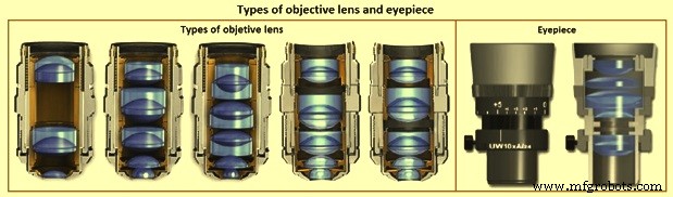
图 4 物镜和目镜的类型
目镜 – 它也被称为目镜。目镜(图 4)放大物镜产生的主要图像。然后眼睛可以使用物镜的全分辨率能力。显微镜在最清晰的视觉点产生样品的虚拟图像,通常距离眼睛 250 毫米。目镜放大该图像,从而获得有用的放大倍数。标准目镜的视场直径为 24 毫米,而用于平面物镜的宽视场目镜的视场直径为 30 毫米,从而增加了主图像的可用面积。
最简单的目镜是惠更斯目镜,其设计是由 C. Huygens 发明的。它由两个平凸透镜组成,它们的凸面朝向物镜。它适用于低功率和中等功率消色差物镜。补偿目镜用于高 NA 消色差和更高校正的物镜。由于使用这些目镜进行一些镜头校正,因此目镜要与所使用的物镜类型相匹配。
眼球间隙是眼睛的眼球晶状体与眼睛之间的距离。对于大多数目镜,眼睛间隙为 10 毫米或更小,如果使用显微镜的人戴眼镜,这是不够的。使用微调焦距可以解决简单的视力问题,例如近视。散光等视力问题不能用显微镜矫正,必须戴眼镜。高眼点目镜可提供眼镜所需的约 20 毫米的眼距。
目镜通常配备有各种标线或标线,用于定位、测量、计数或比较微结构。目镜放大标线或标线图像和主图像。两个图像要同时对焦。还生产了特殊的目镜,以允许比使用刻度尺进行更准确的测量。例子是丝状微米目镜或螺旋微米目镜。此类设备可以自动生成测量值的直接数字读数,精确到 1 微米左右。
通常使用 10 倍放大的目镜,但是为了获得标准放大倍率,一些系统需要其他放大倍率,例如 6.3 倍。更高倍率的目镜,例如 1×、15×、20× 或 25×,在某些情况下也很有用。通过将物镜放大倍率 Mo 乘以目镜放大倍率 Me 可以找到整体放大倍率(图 2)。如果还使用变焦系统或波纹管,则放大倍率将相应更改。
舞台 – 提供用于聚焦和移动样品的机械平台,将其放置在平台上并使用夹子固定。倒置显微镜的载物台具有可更换的具有不同尺寸孔的中心载物台板。抛光的表面靠着孔放置以供观察。但是,无法查看整个表面,并且在高放大倍率下,由于工作距离的限制,无法将物镜聚焦在孔边缘附近。在正置显微镜的情况下,样品被放置在载物台上的载玻片上。由于抛光表面要垂直于光束,因此将粘土放置在样品底部和载玻片之间。将一块镜片纸放在抛光表面上,然后使用整平机将样品压入粘土中。然而,组织碎片可以粘附到样品表面。另一种方法,特别适用于已安装的样品,是使用环代替纸巾来压平样品。铝环或不锈钢环的尺寸与底座相同(在虎钳中略微变平)位于底座而不是样品上。
直立显微镜可以用任何物镜观察整个表面,操作员可以看到正在观察样品的哪个部分。在检查涂层样品、焊缝和其他要检查特定区域的样品上的特定区域时,这是一个有用的功能。对于镶样样品,自动调平载物台支架可以消除样品在粘土上的调平。
舞台是刚性的,以消除振动。由 x 和 y 微米控制的载物台运动是平稳和精确的,因此通常使用齿条和小齿轮传动装置。许多平台具有用于测量 x 和 y 方向上的距离的刻度。聚焦控件经常包含用于估计垂直运动的规则。一些单位有电动载物台和焦点控制。
圆形可旋转载物台板可以方便偏振光检查。这样的阶段,常见于矿物学或岩相学研究,被分级以允许测量旋转角度。直线台通常放置在圆形台的顶部。
站立 – 台式显微镜需要一个刚性支架,尤其是在该装置上进行光学显微镜检查时。组装时,显微镜的各个部件都安装在支架上。在某些情况下,台式显微镜被放置在一个单独的支架上,该支架也可以容纳摄影系统。
镜片缺陷
许多镜片缺陷是由反射和折射定律引起的。透镜的折射率随光的波长而变化,透镜的焦距随折射率而变化。因此,不同颜色的光的焦距会发生变化。存在的每个波长的单独图像聚焦在距镜头的不同距离处。这是纵向色差(图 5)。此外,放大倍率随焦距而变化,从而改变图像的大小。这是横向色差(图 5)。这些差异将被消除以产生彩色照片。由于消色差镜对这些问题的校正有限,因此将它们与黄绿色光过滤一起使用以获得清晰的图像。球面像差(图 5)发生在来自光轴上的点状物体的光线在镜头中心或周边发生更强的折射时,会产生一系列焦点位置,在这些焦点位置上,点像会显示为有限区域的圆.这可以通过使用将物镜的使用限制在中心部分的孔径来最小化。镜头设计也能部分纠正这个问题。
由于最佳焦点的图像表面是弯曲的,因此使用具有相等但相反曲率的补偿目镜来产生平坦的图像。其他问题,如彗差和散光,除非得到纠正,否则会影响图像质量。
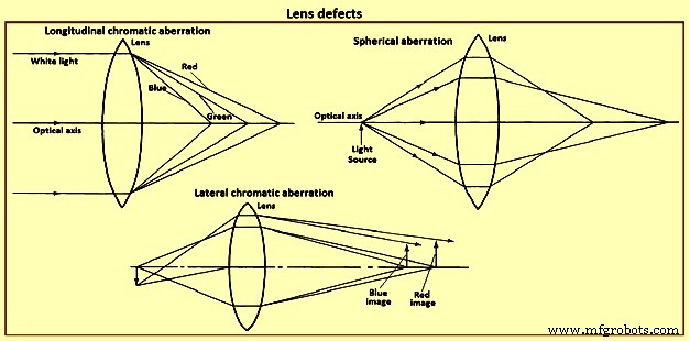
图 5 镜片缺陷
分辨率
为了看到微观结构细节,光学系统需要产生足够的分辨率或分辨能力,以及足够的图像对比度。如果分辨率可以接受但缺乏对比度,则无法观察到细节。通常,分辨距离为“d”的两点或线的能力是入射光的波长“l”和数值孔径 NA, 的函数 的目标。这遵循等式“d =k.l / NA”,其中 k 为 0.5 或 0.61。图 6 显示了 k =0.61 和四个光波长的这种关系。其他公式也有报道。该等式不包括影响分辨率的其他因素,例如物镜的校正程度和通过显微镜观察的人的视力。它是基于阿贝在金相学中不存在的条件下所做的工作,例如自发光点、完美的黑白对比度、透射光检查、理想的点光源以及没有透镜缺陷。
使用上一段中的公式,NA 为 1.4 的物镜的分辨率极限约为 0.2 微米。要看到相距0.2微米的线或点,需要用物镜的分辨能力除以人眼的分辨能力来确定所需的放大倍率,这在观察条件下很难确定。阿贝在 250 毫米的距离处使用 0.3 毫米的值,这是与眼睛的距离以获得最佳视力。对于平均波长为 0.55 微米的光,所需的放大倍率是物镜 NA 的 1,100 倍。这是最大有用放大倍率的 1,000 NA 规则的起源。任何超过 1000 NA 的放大倍率都被称为“空”或无用。
严格遵守 1,000 NA 规则是值得质疑的,考虑到它的发展条件,这肯定与金相学中遇到的条件大不相同。根据阿贝分析,对于使用具有最佳 20/20 视力和最佳对比度条件和平均光波长为 550 nm 的光学显微镜的人,充分利用物镜 NA 的最低放大倍率是 NA 的 550 倍。 这建立了用于给定物镜的有用的最小放大倍率。有人建议,普通人使用光学显微镜的有效放大倍率上限为 2200 NA, 不是 1,000 NA。
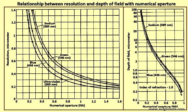
图6 分辨率与景深与数值孔径的关系
景深
景深是沿光轴以可接受的清晰度观察图像细节的距离。影响分辨率的那些因素也会影响景深,但方向相反。因此,要在这两个参数之间达成妥协,随着放大倍数的增加,这变得更加困难。这是高倍率检查首选光刻蚀的原因之一。
考试模式
为了达到所选物镜的分辨率能力,图像对比度应足够。图像对比度取决于样品制备和光学。样品表面的光反射率差异产生放大后肉眼可见的幅度特征。由光反射产生的相位差将通过使用显微镜的相位对比或干涉对比附件呈现出来。
明场照明 – 明场垂直照明是使用最广泛的观察方法,占所拍摄显微照片的绝大部分。在操作中,光穿过物镜并垂直撞击样品表面。与入射光垂直的表面特征将光通过物镜反射回目镜,在目镜处表面特征显得明亮。与光束倾斜的表面向物镜反射的光更少,并且看起来更暗,具体取决于它们的角度。
倾斜照明 – 对于某些显微镜,可以使聚光镜组件或反射镜偏心,使通过物镜的光以非垂直角度照射样品表面。样品表面的粗糙度会产生阴影,从而产生三维外观。这允许确定凸出或凹入的特征。但是,可以引入很少的倾斜,因为这种技术会导致照明变得不均匀并降低分辨率。
在暗场照明中 – 在暗场照明中,从倾斜定向的特征反射的光被收集,从垂直于入射光束的特征反射的光线被阻挡。因此,对比度与明场照明的对比度基本相反;也就是说,在明场照明中较亮的特征显得较暗,而通常较暗的特征显得较亮。这会产生非常强烈的图像对比度,倾斜的特征看起来很明亮。在这种情况下,经常可以看到使用明场照明不可见的特征。这种方法对于研究晶粒结构特别有用。然而,低光强使显微照相更加困难,而使用自动曝光控制装置可以缓解这一问题。
偏振光 – 金相学中使用的偏振光通常仅限于观察某些光学各向异性金属,例如铍、α-钛、锆和铀,这些金属很难蚀刻,但在适当抛光后对偏振光反应良好。在电子微探针分析仪 (EMPA) 和能量色散光谱仪 (EDS) 开发之前,偏振光检查是识别夹杂物方法的一个组成部分。 Since the development of these instruments, polarized light has been used less frequently for this purpose, since identification with the EMPA or EDS techniques is more definitive. Most metallurgical microscopes now use synthetic Polaroid filters. The ‘polarizer’ is placed in the light path before the objective, and the ‘analyzer’ is placed in the light path after the objective, normally just below the eyepiece.
Light consists of transverse waves vibrating in all directions at right angles to the direction of propagation. These vibrations occur symmetrically around the direction of propagation and are unpolarized. When light passes through a polarizing filter, the vibrations occur in only one plane in the direction of propagation, and the light is termed plane polarized. This plane changes as the filter is rotated. When the analyzer filter is placed in the light path, plane polarized light passes through it if the plane of vibration of the light is parallel to the plane of vibration of the analyzer. If the plane of vibration of the analyzer is perpendicular to that of the light the light does not pass through, and extinction results. When plane-polarized light is reflected from the surface of an isotropic metal (any metal with a cubic crystallographic structure, such as iron), then passes through the analyzer in the crossed position (plane of vibration perpendicular to that of the plane-polarized light), the image is extinguished, or dark. However, in practice, since the metallurgical microscope does not produce perfectly plane-polarized light, complete extinction does not occur. This is not a serious problem, since polarized light is used only in a qualitative manner in metallography. Strain-free objectives, normally achromats, are to be used. Fluorite or apochromatic objectives are unsuitable. A strong white-light source is needed to produce accurate colour effects.
If an optically anisotropic, polished metal is placed under the light beam with the polarizer and analyzer crossed, the microstructure is revealed. The quality of sample preparation is very important, and the surface is to be perpendicular to the light path. Rotation of the sample under the beam changes light intensity and colour. Since it is difficult to set the polarizer and analyzer in the crossed position accurately when an anisotropic sample is in place unless the crossed positions are marked on the polarizer and the analyzer, it is best to find this position first using an isotropic sample.
When plane-polarized light strikes an anisotropic metal surface, reflection occurs as two plane-polarized components at right angles to each other. The directions vary with crystal structure. The strength of these two perpendicular reflections can change, and a phase difference exists between them. These differences vary with each metal and depend on the crystal orientation. No reflection is obtained when the basal plane of hexagonal or tetragonal crystals is perpendicular to the light beam. Maximum reflectance occurs when the principal symmetry axis of the crystal is perpendicular to the light beam. The resultant image is predominantly influenced by these orientation effects with phase differences are of little significance.
When the analyzer is crossed with respect to the polarizer, rotation of plane-polarized light from the anisotropic surface allows the light to pass through the analyzer, producing an image in which each grain has a different light intensity and colour, depending on its crystal orientation relative to the light beam. As the stage is rotated, each grain changes four times in intensity from light to dark during a 360 degree rotation. If the phase difference is appreciable, the light is elliptically polarized, the difference in intensity in each grain with rotation is less, and extinction is not observed. Colour images are obtained when the reflected plane-polarized light varies with wavelength. When little colour is present, a sensitive tint plate inserted between the polarizer and the objective enhance colouration.
Isotropic metals can be examined using crossed-polarized light if the surface can be rendered optically active by etching, staining, or anodizing. Procedures have been developed for several metals, however, all etched surfaces do not respond to polarized light. Normally, the etch s to produce etch pits or facets in each grain to cause double reflection at these features. Grains with different crystal orientations produce differently oriented pits or facets, yielding different degrees of elliptical polarization and hence varying light intensity. Anodizing produces a thick oxide film on the sample surface and irregularities in the film lead to double reflection.
Although the polarization response of anodized samples has been attributed to optical anisotropy of the film, experimentation has shown that the effect is due to film surface irregularities. Tint etchants produce surface films which result in interference colours which can be enhanced using polarized light. In general, best results are achieved when the analyzer is shifted slightly from the crossed position. In addition to its use in examining inclusions, anisotropic metals (antimony, beryllium, bismuth, cadmium, cobalt, magnesium, scandium, tellurium, tin, titanium, uranium, zinc, and zirconium, for example), and etched / anodized/ tint-etched cubic metals, polarized light is useful for examination of coated or deformed metals. Phase identification can also be aided in some cases. The internal structure of graphite nodules in cast iron is vividly revealed using polarized light. Martensitic structures are frequently better revealed using polarized light, which illustrate lath martensite in a high-strength iron-base alloy.
Phase contrast illumination – It permits examination of subtle phase variations in microstructures with little or no amplitude contrast from differences in the optical path at the surface (reflected light) or from differences in the optical path through the sample (transmitted light). Differences of height as small as 0.005 micrometers can be detected. Application of phase-contrast illumination in metallography has been limited. The technique needs a separate set of objectives and a special vertical illuminator.
Interference-contrast illumination – Differential interference-contrast illumination produces images with emphasized topographic detail similar to those observed using oblique illumination. Detail which is invisible or faintly visible using bright-field illumination can be revealed vividly with interference-contrast illumination. Examples of the topographic detail which can be revealed using differential interference-contrast illumination are the relative hardness of the constituents or the nature of the etching process, that is, which areas or constituents are attacked by the etchant. In some cases, other aspects of the structure can be revealed which are invisible or faintly visible in bright-field illumination.
Interference techniques – Several interference techniques are used to measure height differences on samples. Interference fringes on a perfectly flat surface appear as straight, parallel lines of equal width and spacing. Height variations cause these fringes to appear curved or jagged, depending on the unit used. The interference microscope divides the light from a single point source into two or more waves which are superimposed after traveling different paths. This produces interference. Two-beam and multiple-beam instruments are the two basic types of interferometers used. The measurements are based on the wavelength of the light used. Two-beam interferometers can measure height differences as small as ‘l’/20; multiple-beam interferometers, as small as ‘l’/200.
The Linnik-type interferometer is a two-beam reflecting microscope which uses non-polarized light. A beam-splitting prism produces two light beams from a monochromatic light source. One beam travels through the test piece objective to the test piece surface and is reflected back through the objective to the eyepiece. The other beam travels through the reference objective, strikes an optically flat reference mirror, and returns to the beam splitter, then to the eyepiece. If the path difference between the two beams is not equal or not a multiple of ‘l’/2, interference occurs and contour lines are formed which indicate locations of equal elevation. The height difference between adjacent fringes is ‘l’/2.
The Tolansky multiple-beam interferometer produces interference between many light beams by placing a reference mirror which is partially transmitting and partially reflecting very near the sample surface but slightly out of parallel. The reference mirror has a known reflectivity selected to approximate that of the surface. Light passes through the reference mirror and strikes the sample surface, is reflected by the sample surface, and interferes with the rays reflected between the reference mirror and the sample. The fringes produced by the multiple-beam interferometer are sharper than those from the two-beam interferometer, which accounts for the greater accuracy. The distance between the fringes is also ’l’/2. Elevations produce displacements of the fringes from parallel alignment. The displacement is compared to the distance between the fringes to obtain height measurements.
Light-section microscopy – The light-section microscope, also used to measure surface topography, complements interference techniques. Roughness differences from 1 micrometer to 400 micrometers can be measured, which is useful in examining machined surfaces and for measurement of surface layers or films. In operation, a slit is placed near the field iris in the illumination system and is imaged by an objective as a light line on the surface to be measured. Oblique illumination is used with a dark background. The light band is observed using a second objective which is identical to the first. The objectives are 45 degrees to the sample surface and 90 degrees to each other. A reticle in the eyepiece is used for measurements, or they are made on photographs. Vertical resolution is not as good as with interferometers, but lateral resolution is better.
Auxiliary techniques
Several special devices can be used with the optical microscope to get additional information. These techniques are described below.
Micro-hardness testing – Micro-indentation hardness data can be obtained by adding indenter attachments to the microscope. Single-purpose units also are made by many manufacturers of hardness test equipment. Loads are normally made from 1 g (gram) to 1,000 g, although some manufacturers have units for low loads (0.05 g to 200 g). Knoop or Vickers indenters can be used.
Hot-stage microscopy – Hot-stage microscope cells are available from several manufacturers. Single-purpose units can also be used. Cold-cell attachments have also been produced, but have rather limited use in metallography. The hot-stage microscope has been used to study phase transformations on heating or cooling or at constant temperature. Examination of reactions in the hot-stage microscope cell needs use of long-working-distance objectives, since the sample is held within the cell. Moreover, since the cell window is quartz, the objectives is to be quartz-corrected, especially those with magnifications of 20× or more.
Techniques other than chemical etching are to be used to view phase changes. Grain boundaries are to be thermally etched if the sample is held at a constant temperature in the vacuum. Grain-boundary grooving is easily observed using bright field illumination. Phase transformations are visible by the relief produced at the surface. Hence, shear reactions, such as those produced by martensite or bainite formation, are most easily observed. Other phase transformations are more difficult or impossible to observe. Transformations can be photographed in situ, for which motion picture cameras are normally used.
Special stages – These are available in a variety of configurations. Auto leveling stages for mounted samples are a typical example. Universal tilting stages have also been made for rapid manipulation of rough, irregular samples. Special stages have also been designed for handling small objects. A number of stages have been made for performing in situ experiments. Basic studies of solidification have been performed by in situ observation of the freezing of low-melting-point organic materials, such as camphene, which solidify like metals. Observation of the recrystallization of low-melting-point metals and alloys has been similarly observed. Special stages have been used to observe the progress of electrolytic polishing and etching. Cells have also been used for in situ examination of corrosion processes. Stages have been designed to observe a variety of processes involving static or dynamic stress, and devices have also been designed to permit physical extraction of inclusions.
Hot-cell microscopy – Metallographic preparation of radioactive materials needs remote-control preparation using specially designed hot cells. Special microscopes have been designed for use with the hot cell.
Field microscopy – When the microstructure of a component or large object which cannot be cut and moved to the laboratory is to be examined, portable laboratory equipment, made by several manufacturers, can be used to polish a section in situ. A portable microscope can be sometimes used to examine and photograph the microstructure. If this cannot be done, replicas can be made and examined using an optical microscope or an electron microscope.
Comparison microscopes – The need occasionally arises to compare two microstructures. Normally, this is carried out by placing micrographs from each sample side-by-side, but it can also be performed using special microscopes. A bridge comparator is used to combine images from two bench microscopes for simultaneous viewing.
Television monitors – Projection microscopes can be used for group viewing, but it is more common to display the microstructure on a black-and-white or colour monitor. A number of high-resolution closed-circuit systems are available.
Clean-room microscopy – The study of small particles is influenced by dust contamination during viewing. Hence, such work is to be performed in a clean box, clean bench, or clean room which is specially made to provide a dust free environment.
Image analyzers – The increased use of quantitative metallography, particularly for characterization of inclusions, has promoted development of automated image analysis systems based on television principles. Phases or constituents of interest are detected primarily by differences in light reflectivity which produce gray-level differences on the monitor. Majority of the stereological measurements can be made using these systems. Considerable automation has been achieved using automated stages and powerful minicomputers. Although these devices can be quite expensive, they have stimulated interest in stereology and its application to structure-property correlations.
Features are detected on as-polished or etched samples, depending on the nature of the feature of interest. If etching is needed, selective techniques are normally used. Field and feature-specific measurements are utilized. Field measurements measure all the detected features simultaneously, as in volume fraction measurements. In feature-specific measurements, each separate particle is measured sequentially. This procedure is normally used for shape and size measurements.
Some structures do not lend themselves to accurate measurements using such systems. For example, quantification of fracture surface detail cannot be performed using an automatic image analyzer, since the device cannot separate fracture features by gray level. Many transmission electron micrograph structures also cannot be analyzed using these devices. For such structures, semi-automatic tracing devices can be used with the operator performing detection with a light pen or stylus. These lower-cost systems can be used for nearly any stereological measurement. Because of the greater time needed for detection, they are less suitable for measurement problems which need sampling of many fields.
Photo-microscopy
Prior to the development of photographic attachments, microstructures were to be sketched. Although the need for such documentation is no more there, sketching remains useful as a teaching method. Photo-microscopy is important in metallography, since the photo-micrograph can faithfully reproduce the detail observed for others to view. With the equipment presently available, high-quality micrographs are easily produced. However, this needs careful attention to sample preparation, etching, and use of the microscope. Reproduction of false microstructures is all too common and has caused inaccurate interpretations, rejection of good materials, and faulty conclusions in failure analyses.
Historically, darkroom photographic procedures have been most prevalent. Since the introduction of instant photographic processes such as Polaroid, however, many photo-micrographs have been made using these materials, taking advantage of their speed and efficiency. However, image reproduction is sacrificed, and the process is to be repeated for each extra copy. Use of an automatic exposure device is necessary with instant process film to minimize waste. Traditional darkroom photographic methods need more effort, but yield better micrographs. Considerable automation in wet darkroom processes is possible, but frequent use of photo-microscopy is needed to justify the cost of such equipment.
Obtaining good micrographs needs adequate image contrast and resolution, uniform focus over the entire field, uniform lighting, and adequate depth of field. The light source is to be properly aligned, and the system is to be free of vibration. The yellow-green filter is to be employed to correct lens defects. The optics is to be clean, and the field and aperture diaphragms are to be adjusted correctly. The microscope is focused in a variety of ways, depending on the model. Several film formats can be used, such as plates, sheet film of different size, or 35-mm roll film. The magnification at the film plane is to be known. This is a simple procedure if the only variables are the objective and eyepiece magnification, but is more difficult when using a zoom system or bellows. A stage micrometer can be utilized to determine the true magnification.
A range of black-and-white and colour films is available for darkroom or instant techniques. The manufacturers of these films document film characteristics. Black-and-white films are normally used due to their lower cost. They show better contrast control, are easier to process, and are normally quicker to use than colour films. Colour film has some important uses for which its cost is justified. In traditional black-and-white photography, a negative image is produced first and is used to produce a positive image of the microstructure on suitable paper. The micrograph lasts for many years without any apparent change. Selection of the negative film is based on the format available, colour sensitivity, contrast, resolving power, speed, graininess, and exposure and development latitudes.
Some black-and-white films are not sensitive to the entire visible spectrum. Orthochromatic films are sensitive to all colours except orange and red. Panchromatic films are sensitive to all colours, although they emphasize blue and de-emphasize yellow. A yellow filter can be used to reduce this colour bias.
Orthochromatic films can be developed under dark red light, but panchromatic films need total darkness. Orthochromatic films are very good for photo-microscopy, particularly when a yellow-green filter is inserted to correct lens defects.
Film speed is a critical variable only when illumination is low, as in polarized light, interference-contrast, or dark-field illumination. Orthochromatic film has a medium contrast which is adequate for most structures. Contrast can be enhanced with a high-contrast film. The resolving power of a film defines its ability to record fine details in the image. Hence, a high-resolving-power film is desirable. Graininess depends on the size of the silver grains in the emulsion, the developer used, and the development time and temperature. High-speed films are grainier than low-speed films, making them less suitable for enlarging. Contact printing is preferred. It needs a large film size, but saves enlargement time. It produces better images and eliminates re-determining the magnification of the print. A fine-grain film provides the best resolution.
When a negative is exposed, there is an allowable range of exposures which produces a useful, printable negative. Wide exposure latitude is quite valuable. Each film includes information on its characteristic relationship between exposure time and density. The exposure selected is to be on the linear portion of the density-time curve. A good, dense negative allows suppression of some of the fine image defects during printing. An underexposed negative greatly restricts printing and normally results in a poor print. Development of negatives is rather simple and involves use of a developing solution, a stop bath, a fixing solution, as well as washing and drying.
The correct exposure is most easily determined using a built-in exposure meter. If this is not available, a test exposure series can be made. This is accomplished by pulling out the film slide completely and exposing the entire film for a time judged to be considerably shorter than that needed. The slide is then inserted so that it covers around 10 mm to 20 mm of the film, and the exposure is repeated. This is repeated incrementally until the slide is fully inserted, covering the film. After development, the correct time can be assessed based on the density of the negative in each band.
Alternatively, the step exposure can be performed using an instant film of the same speed, saving the darkroom time. Majority of the black-and-white films are contact printed. The negative is placed emulsion side up on the contact printer, and a suitable paper is placed emulsion side down over the negative. The printer is closed, and light is passed through the film onto the paper. The print is developed, stopped, fixed, washed, and dried. Print contrast is controlled by the type of paper and development time. Print contrast types vary from extra-soft (flat) to extra-contrast (grades 1 to 5). Number 3 paper is used most frequently. Number 4 paper is used to increase contrast, and No. 2 paper to reduce contrast.
Instant process films eliminate the darkroom work, thus hastening the process. Polaroid prints use the diffusion-transfer reversal process. Development begins when the film is removed from the camera after the exposure. The action of pulling the film out of the camera crushes a pod containing the viscous, caustic developer and spreads it over the film. Black-and-white films develop rapidly while the colour prints need slightly more time. Some of the Polaroid films have very high speeds, an advantage in dim lighting. Some prints are to be coated with a neutralizing stabilizer / protective varnish to prevent staining and fading. Also available are instant films which produce a negative and a positive print. This negative is to be cleared, but a darkroom is not required. Polaroid films used in microscopy are all panchromatic. They are available as roll film, film packs, or sheets. Exposure times are to be more accurately controlled to get good prints than with traditional wet-process films.
Macro-photography
Examination and photography are frequently needed for such objects as macro-etched disks and broken parts. Examination can be performed visually or with the aid of a simple hand lens or stereo-microscope. Macro-photography can be performed using majority of the cameras, perhaps aided by the use of close-up lens attachments, a bellows, or a macro-lens. Many stereomicroscopes can be equipped with cameras for photography while some takes stereo-pairs. A few manufacturers offer camera stands for macro-photography. Some metallographs also have low-magnification objectives which can perform certain types of macro-photography.
Macro-photography utilizes magnifications from less than 1× to 50×. Most laboratories, especially those engaged in failure analyses, have various cameras, light sources, and stereo-viewers to cover the wide range of objects photographed. Correct lighting is necessary to emphasize details and provide even illumination without glare or reflection. Adjustment of lighting needs some experimentation and experience. Available lighting includes flood lamps, rings, coaxial, or fiber optics. A light box is useful for eliminating shadows, but considerable creativity is needed to achieve good results.
Depth of field and resolution are important variables. Many of the objects to be photographed are three-dimensional, which needs a certain depth of field and proper lighting to reveal shape and texture. Depth of field varies with the aperture diaphragm lens setting, the magnification, and the focal length of the lens. Stopping down the aperture improves depth of field, but decreases image brightness and clarity. Depth of field also increases as magnification decreases and focal length increases. For magnifications below 5×, focal lengths of 100 mm or more are preferred. Shorter-focal-length lenses are used for higher magnifications.
制造工艺