

Verilog 4 对 1 多路复用器/复用器
什么是多路复用器或多路复用器?
多路复用器或 mux 简而言之,它是一种基于选择信号将数据从 N 个输入之一传输到输出的数字元件。下面显示的情况是 N 等于 4。例如,一个 4 位多路复用器将有 N 个输入,每一个 4 位,每个输入都可以通过使用选择信号传输到输出。
<无脚本>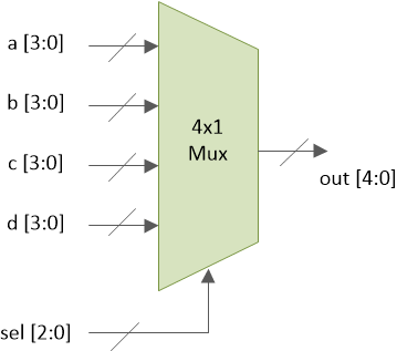
sel 是一个 2 位输入,可以有四个值。选择线上的每个值都将允许将其中一个输入发送到输出引脚。
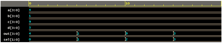
	sel     a     b     c     d     out
	 0     3    7     1     9    3
	 1      3    7    1     9    7
	 2      3     7    1    9    1
	 3      3     7     1    9   9
一个 4x1 多路复用器可以通过多种方式实现,这里您将看到两种最常见的方式:
- 使用
assign声明 - 使用
case声明
使用 assign 声明
module mux_4to1_assign ( input [3:0] a,                 // 4-bit input called a
                         input [3:0] b,                 // 4-bit input called b
                         input [3:0] c,                 // 4-bit input called c
                         input [3:0] d,                 // 4-bit input called d
                         input [1:0] sel,               // input sel used to select between a,b,c,d
                         output [3:0] out);             // 4-bit output based on input sel

   // When sel[1] is 0, (sel[0]? b:a) is selected and when sel[1] is 1, (sel[0] ? d:c) is taken
   // When sel[0] is 0, a is sent to output, else b and when sel[0] is 0, c is sent to output, else d
   assign out = sel[1] ? (sel[0] ? d : c) : (sel[0] ? b : a);

endmodule
名为 mux_4x1_assign 的模块 具有四个 4 位数据输入、一个 2 位选择输入和一个 4 位数据输出。多路复用器将使用 assign 根据选择信号 sel 选择 a、b、c 或 d 声明。
使用 case 声明
请注意,信号输出被声明为 reg 类型,因为它用于 程序 像 always 这样的块 .
module mux_4to1_case ( input [3:0] a,                 // 4-bit input called a
                       input [3:0] b,                 // 4-bit input called b
                       input [3:0] c,                 // 4-bit input called c
                       input [3:0] d,                 // 4-bit input called d
                       input [1:0] sel,               // input sel used to select between a,b,c,d
                       output reg [3:0] out);         // 4-bit output based on input sel

   // This always block gets executed whenever a/b/c/d/sel changes value
   // When that happens, based on value in sel, output is assigned to either a/b/c/d
   always @ (a or b or c or d or sel) begin
      case (sel)
         2'b00 : out <= a;
         2'b01 : out <= b;
         2'b10 : out <= c;
         2'b11 : out <= d;
      endcase
   end
endmodule
名为 mux_4x1_case 的模块 具有四个 4 位数据输入、一个 2 位选择输入和一个 4 位数据输出。多路复用器将使用 case 根据选择信号 sel 选择 a、b、c 或 d 声明。
硬件示意图
两种类型的多路复用器模型都被合成到相同的硬件中,如下图所示。
<无脚本>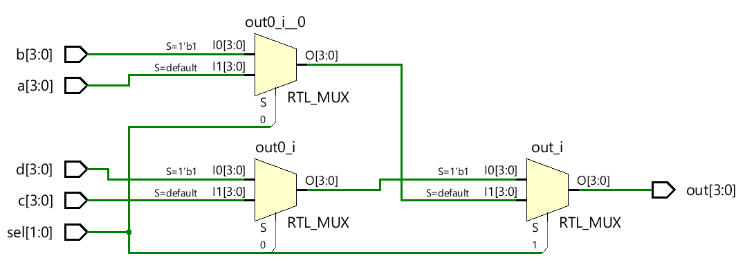
测试台
module tb_4to1_mux;

   // Declare internal reg variables to drive design inputs
   // Declare wire signals to collect design output
   // Declare other internal variables used in testbench
   reg [3:0] a;
   reg [3:0] b;
   reg [3:0] c;
   reg [3:0] d;
   wire [3:0] out;
   reg [1:0] sel;
   integer i;

   // Instantiate one of the designs, in this case, we have used the design with case statement
   // Connect testbench variables declared above with those in the design
   mux_4to1_case  mux0 (   .a (a),
                           .b (b),
                           .c (c),
                           .d (d),
                           .sel (sel),
                           .out (out));

   // This initial block is the stimulus
   initial begin
      // Launch a monitor in background to display values to log whenever a/b/c/d/sel/out changes
      $monitor ("[%0t] sel=0x%0h a=0x%0h b=0x%0h c=0x%0h d=0x%0h out=0x%0h", $time, sel, a, b, c, d, out);

   	  // 1. At time 0, drive random values to a/b/c/d and keep sel = 0
      sel <= 0;
      a <= $random;
      b <= $random;
      c <= $random;
      d <= $random;

      // 2. Change the value of sel after every 5ns
      for (i = 1; i < 4; i=i+1) begin
         #5 sel <= i;
      end

      // 3. After Step2 is over, wait for 5ns and finish simulation
      #5 $finish;
   end
endmodule
模拟日志ncsim> run [0] sel=0x0 a=0x4 b=0x1 c=0x9 d=0x3 out=0x4 [5] sel=0x1 a=0x4 b=0x1 c=0x9 d=0x3 out=0x1 [10] sel=0x2 a=0x4 b=0x1 c=0x9 d=0x3 out=0x9 [15] sel=0x3 a=0x4 b=0x1 c=0x9 d=0x3 out=0x3 Simulation complete via $finish(1) at time 20 NS + 0<无脚本>
Verilog