

Verilog 模拟
Verilog 是一种硬件描述语言,设计人员无需模拟其 RTL 设计即可将其转换为逻辑门。那么需要模拟什么?
<无脚本>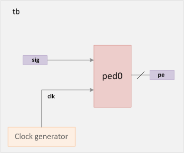
仿真是一种在不同时间对设计应用不同输入激励以检查 RTL 代码是否按照预期方式运行的技术。从本质上讲,仿真是一种被广泛采用的技术,用于验证设计的稳健性。它也类似于制造芯片在现实世界中的使用方式以及它对不同输入的反应方式。
例如,上面的设计表示一个上升沿检测器,其输入时钟和信号以周期性间隔进行评估以找到输出 pe 如图所示。仿真让我们可以查看相关信号的时序图,从而了解 Verilog 中的设计描述实际上是如何表现的。
<无脚本>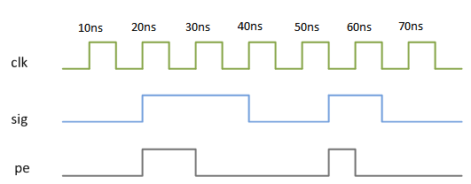
有几家 EDA 公司开发模拟器 能够计算出设计中各种输入的输出。 Verilog 是根据离散事件定义的 执行模型和不同的模拟器可以自由使用不同的算法为用户提供一组一致的结果。 Verilog代码分为多个进程和线程,在模拟过程中可能会在不同的时间进行评估,后面会涉及到。
示例
名为 tb 的测试平台是一个容纳设计模块的容器。然而,在这个例子中,我们没有使用任何设计实例。有两个变量 或信号 可以在特定时间分配特定值。 clk 表示在测试台中生成的时钟。这是由 always 完成的 通过在每 5ns 后交替时钟的值来声明。 initial 块包含一组语句,它们在不同时间为两个信号分配不同的值。
module tb;
  reg clk;
  reg sig;

  // Clock generation
  // Process starts at time 0ns and loops after every 5ns
  always #5 clk = ~clk;

  // Initial block : Process starts at time 0ns
  initial begin
    // This system task will print out the signal values everytime they change
    $monitor("Time = %0t clk = %0d sig = %0d", $time, clk, sig);

    // Also called stimulus, we simply assign different values to the variables
    // after some simulation "delay"
    sig = 0;
    #5 clk = 0;        // Assign clk to 0 at time 5ns
    #15  sig = 1;      // Assign sig to 1 at time 20ns (#5 + #15)
    #20  sig = 0;      // Assign sig to 0 at time 40ns (#5 + #15 + #20)
    #15  sig = 1;      // Assign sig to 1 at time 55ns (#5 + #15 + #20 + #15)
    #10  sig = 0;      // Assign sig to 0 at time 65ns (#5 + #15 + #20 + #15 + #10)
    #20 $finish;       // Finish simulation at time 85ns
  end
endmodule
模拟器执行上述测试台后,提供如下输出。
模拟日志ncsim> run Time = 0 clk = x sig = 0 Time = 5 clk = 0 sig = 0 Time = 10 clk = 1 sig = 0 Time = 15 clk = 0 sig = 0 Time = 20 clk = 1 sig = 1 Time = 25 clk = 0 sig = 1 Time = 30 clk = 1 sig = 1 Time = 35 clk = 0 sig = 1 Time = 40 clk = 1 sig = 0 Time = 45 clk = 0 sig = 0 Time = 50 clk = 1 sig = 0 Time = 55 clk = 0 sig = 1 Time = 60 clk = 1 sig = 1 Time = 65 clk = 0 sig = 0 Time = 70 clk = 1 sig = 0 Time = 75 clk = 0 sig = 0 Time = 80 clk = 1 sig = 0 Simulation complete via $finish(1) at time 85 NS + 0
什么是仿真波形?
仿真使我们能够将设计和测试台信号转储为可以图形表示的波形,以分析和调试 RTL 设计的功能。下图是从 EDA 工具获得的波形,显示了每个信号相对于时间的进展,与之前的时序图相同。
<无脚本>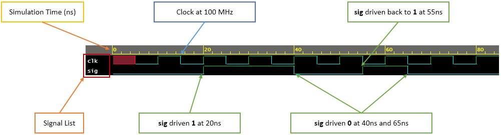
变量或网络值的每一次变化都称为更新事件 .并且进程对更新事件很敏感 这样每当更新事件发生时这些过程就会被评估,并被称为评估事件 .由于可能会任意评估多个进程,因此必须在称为 事件队列 的东西中跟踪更改的顺序 .
当然,它们是按模拟时间排序的。在队列中放置新事件称为调度 .仿真时间用于指代仿真器维护的时间值,以模拟被仿真电路所需的实际时间。上面示例的时间值以纳秒为单位显示 ns 在时序图中。
module des;
	wire abc;
	wire a, b, c;

	assign abc = a & b | c;  // abc is updated via the assign statement (process) whenever a, b or c change -> update event
endmodule
<无脚本> 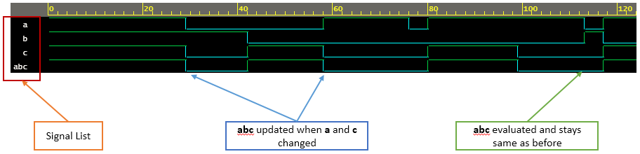
刷新Verilog,看例子!
事件队列中的区域
Verilog 事件队列在逻辑上分为五个区域,可以在其中任意一个区域添加事件。但是,它只能从活动区域中移除。
| 事件 | 说明 |
|---|---|
| 活动 | 发生在当前模拟时间,可以任意顺序处理 |
| 无效 | 在当前模拟时间发生,但在所有活动事件完成后处理 |
| 非阻塞 | 在之前的某个时间进行评估,但在活动和非活动事件完成后的当前模拟时间完成分配 |
| 监视器 | 在所有活动、非活动和非阻塞事件完成后处理 |
| 未来 | 发生在未来的某个模拟时间 |
模拟周期是处理所有活动事件的地方。除少数情况外,该标准保证一定的调度顺序。例如,begin-end 块中的语句只会按照它们出现的顺序执行。
module tb;
	reg [3:0] a;
	reg [3:0] b;

	initial begin		// Statements are executed one after the other at appropriate simulation times
		a = 5;			// At time 0ns, a is assigned 5
		b = 2;			// In the same simulation step (time 0ns), b is assigned 2

		#10 a = 7;		// When simulation advances to 10ns, a is assigned 7
	end
endmodule
事件队列 定义分配给 b 应该在分配给 a 之后发生 .
Verilog