

3D打印类型:3D打印技术的7大类
当大多数人听到“3D 打印”时,他们会想到一台制造塑料零件的小型台式机器。但幕后还有更多事情发生。我们所说的3D打印实际上是一组不同的技术,它们根据数字设计逐层构建物体。
与传统制造不同,传统制造将材料从实心块上雕刻出来,3D 打印机仅添加所需的内容。
根据ISO/ASTM 52900-15标准,3D打印分为七类:还原光聚合、材料喷射、粘合剂喷射、粉末床融合、材料挤出、定向能量沉积和片材层压。每一种方法都使用不同的方法,并且每种方法都有自己的优势,具体取决于您使用的材料、预算以及零件的复杂程度。
当今一些最先进的 3D 打印方法可以追溯到 20 世纪 80 年代。立体光刻 (SLA) 于 1986 年获得专利,从那时起,我们已经看到了巨大的突破,例如 FDM、SLS 和 MJF,每种技术都针对不同的目标而设计:速度、细节、材料范围或成本效率。
现在,您可以找到价格低于 200 美元的台式机和价格超过 100 万美元的工业级系统。从 PLA 和 ABS 到金属粉末、陶瓷和光聚合物树脂,3D 打印行业已发展成为爱好者和制造工程师的重要工具。
在本文中,我们将详细介绍每种主要的 3D 打印类型,探讨它们的工作原理,并帮助您找出最适合您需求的 3D 打印类型,无论您是刚刚开始使用还是正在扩大生产。
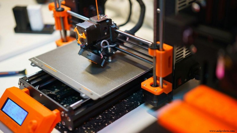
材质挤压
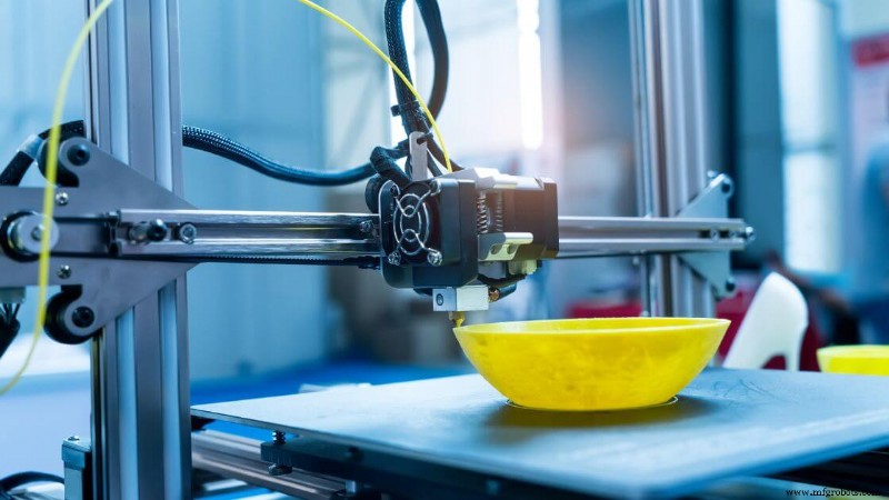
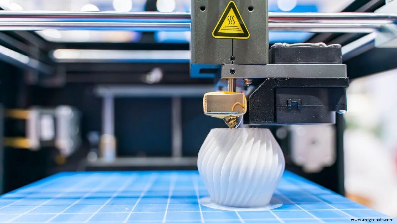 材料挤出是指一组 3D 打印过程,其中构建材料通过喷嘴推动并逐层放置以形成三维零件。
该材料(通常是热塑性塑料)被加热至半液态,然后在计算机辅助设计文件引导的受控路径中挤出。每一层在冷却时都会与前一层融合,形成坚固的结构。
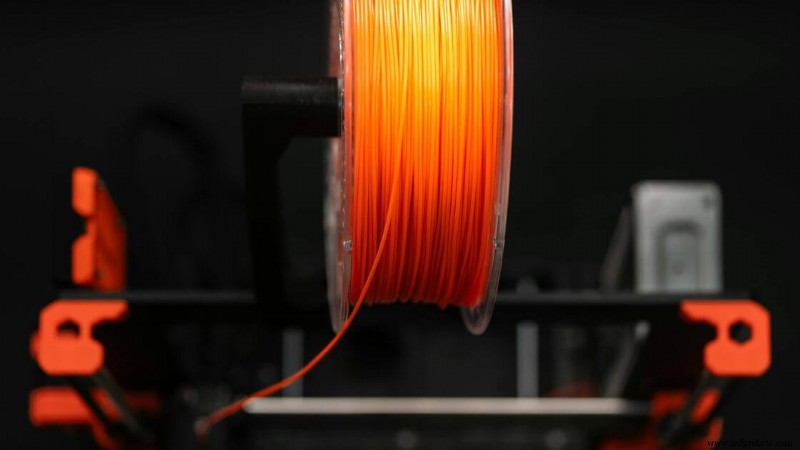
这是最常见且最容易使用的 3D 打印方法类型之一。您经常在使用缠绕线材的桌面 3D 打印机中看到它,但该类别还包括挤出颗粒、混凝土或糊状物的大容量机器。
无论您是生产小型组件还是大型原型,材料挤出都可以在设计和构建体积方面提供显着的灵活性。
支持的 3D 打印材料范围广泛。 PLA、ABS 和 PETG 等标准热塑性塑料很常见,而更先进的设置可以处理碳纤维复合材料、耐温聚合物或金属填充长丝。
有些机器甚至用于建筑或食品建模。
尺寸精度通常在 ±0.5 毫米左右,尽管这因设备、材料和环境控制而异。具有悬垂的物体通常需要支撑结构以防止打印过程中倒塌。可能需要进行后处理以提高表面光洁度并去除支撑。
由于其成本效益,材料挤出仍然是原型制作的主要选择,特别是与选择性激光烧结或立体光刻等更复杂的技术相比。它还作为熔融沉积建模的基础,熔融沉积建模是此类别的广泛使用的实现。
熔融沉积成型 (FDM) 或熔融长丝制造 (FFF)
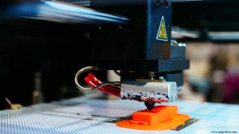
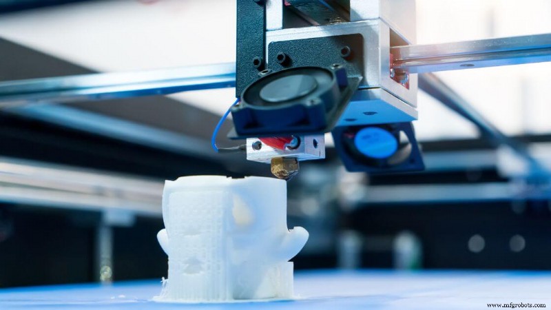
熔融沉积建模,也称为熔融长丝制造,是一种材料挤出,其中热塑性长丝被送入加热的打印头。材料熔化并通过喷嘴挤出,在打印平台上冷却并固化时形成 3D 物体的每一层。
您通常会使用 PLA、ABS、PETG 和 TPU 等材料。更先进的选项包括聚碳酸酯、ULTEM 以及填充碳纤维或金属粉末的长丝。这些细丝可以根据您零件的功能要求提供不同的机械性能。
此过程非常适合快速原型制作、教育模型、消费产品测试以及夹具或固定装置等制造辅助工具等应用。
FDM 3D 打印在产品开发工作流程中也很常见,其中需要在批量生产之前评估零件几何形状或装配配合。
典型精度范围约为 ±0.5 毫米,层分辨率通常为 50 至 300 微米。打印速度根据材料和零件复杂程度而变化,但标准速率在 40 至 100 毫米/秒之间。
优点:
- 成本低:入门级打印机和耗材随处可见,价格实惠。
- 材料多样性:具有各种强度、颜色和饰面的多种塑料可供选择。
- 易于使用:简单的软件工作流程使初学者和专业人士都可以轻松使用。
- 可扩展性:从台式机到具有大量构建量的工业规模系统。
缺点:
- 可见的层线:除非应用后处理,否则部件通常会在层之间显示脊线。
- 层间结合力较弱:机械性能可能会因零件方向的不同而不一致。
- 支撑要求:悬挑和桥梁可能需要额外的材料,这些材料必须稍后移除。
- 精度较低:与树脂 3D 打印或粉末床融合相比,FDM 可能难以处理精细的细节。
3D生物打印
 3D 生物打印是一种特殊的材料挤出形式,它使用生物墨水(通常由悬浮在水凝胶中的活细胞制成)逐层创建组织样结构。
与依赖热塑性塑料或金属粉末的传统 3D 打印方法不同,该工艺优先考虑细胞活力和生物材料兼容性。
挤压必须足够精确和温和,以避免损坏生命成分,同时形成功能性生物几何形状。
在此过程中您会发现的材料包括可生物降解的聚合物,如藻酸盐、胶原蛋白、明胶和纤维蛋白。
它们充当支持细胞生长和排列的支架。由于结构需要模仿真实组织,因此选择这些材料是因为它们具有兼容性、灵活性和支持血管化的能力。
应用正在迅速推进。您将看到 3D 生物打印用于芯片器官设备、组织支架、再生医学模型,甚至皮肤或软骨的早期生物制造的研究。这些不仅仅是概念模型,它们是迈向未来植入式解决方案的实际步骤。
尺寸精度可以达到 100-200 微米或更精细,具体取决于打印机校准和生物墨水粘度。然而,性能会根据湿度、打印头控制和无菌等环境因素而有所不同。
打印速度取决于细胞密度、喷嘴尺寸和水凝胶流速。通常,打印速度比聚合物挤出速度慢,因为维持细胞健康比速度更重要。
优点:
- 组织工程潜力:提供实现功能器官和再生疗法的途径。
- 可定制性:用于药物测试或患者特定植入物的定制结构。
- 逐层控制:支持不同细胞类型的空间放置。
缺点:
- 复杂性高:需要严格控制温度、无菌和生物墨水的一致性。
- 寿命有限:打印结构通常需要立即培养或调节。
- 监管障碍:临床使用涉及广泛的测试和合规步骤。
建筑 3D 打印
建筑 3D 打印是一种大规模增材制造方法,它使用自动挤出系统(通常是机械臂或龙门安装喷嘴)以分层结构沉积建筑级材料,例如混凝土。
与传统方法不同,它使用 3D 打印技术直接从数字模型构建,无需标准模具或模板即可逐层生产墙壁、结构外壳甚至整个建筑物。
您通常会看到这些系统中使用的材料,如水泥混合物、速凝混凝土、地质聚合物化合物和专用砂浆。
基材的选择必须满足严格的流动性和固化要求,确保每个新部件层与前一层部件良好粘合,同时保持结构完整性。
这种方法在旨在可持续、快速和低成本建设的项目中获得了全球关注。从保障性住房到紧急避难所和艺术建筑,应用范围正在不断扩大。
虽然它仍处于新兴阶段,但您会发现几个现实世界的示例,其中 3D 打印机在短短几天内就创建了整个房屋或关键结构部件,比传统的施工时间节省了数周。
精度通常在 ±5 毫米到 ±10 毫米之间,具体取决于打印机的构建平台尺寸、喷嘴精度和环境因素。打印速度可能有所不同,但通常比直线或重复形状的手工作业更快。层分辨率往往较粗,范围在 10 毫米到 30 毫米之间,但可以使用精加工技术来提高。
优点:
- 减少劳动力需求,尤其是重复性任务
- 显着缩短某些几何形状的构建时间
- 最大限度地减少沉积建模过程中的材料浪费
- 实现传统方法无法实现的新的有机建筑形式
缺点:
- 需要大量设备,限制了移动性和安装简易性
- 材料必须经过精确设计,以实现流动和快速固化
- 规范合规性和检查标准仍在不断发展
- 打印后表面光洁度和零件几何形状可能需要手动细化
还原光聚合
还原光聚合是一种 3D 打印工艺,利用光选择性地将液态树脂层固化成固体部件。首先,您需要一个充满光聚合物树脂的桶,通常是丙烯酸基树脂,它会对特定波长的光产生反应。
激光、数字光投影仪或液晶屏以高精度引导该固化过程。随着每个光聚合物层变硬,构建平台逐渐升高或降低以允许下一层形成。重复此序列直到整个对象完成。
这种方法的独特之处在于它能够产生极其精细的细节和超光滑的表面光洁度。这就是为什么它受到精度至关重要的应用的青睐,例如牙科模具、复杂的珠宝和小型医疗组件。
尺寸精度可以在 ±0.1 毫米以内,在经过微调的机器上甚至更好,并且由于受控的曝光和树脂流动行为,零件几何形状保持一致。
您还会发现此过程有多种格式(SLA、DLP 和 LCD),每种格式使用略有不同的光源,但在相同的一般原理下运行:光聚合。
这些机器中使用的树脂有多种配方,其中一些针对韧性进行了优化,另一些则针对灵活性、透明度或耐温性进行了优化。有些具有生物相容性,可用于医疗原型或手术导板。
但请记住,支撑结构对于某些悬垂或桥梁特征是必需的,并且在打印后必须手动将其移除。紫外光下的后固化通常对于提高机械性能和确保清洁的表面没有任何残留粘性至关重要。
立体光刻 (SLA)
 立体光刻 (SLA) 是第一个在商业上成功的 3D 打印工艺,并且至今仍然是最精确的工艺之一。在 SLA 系统中,紫外激光一次跟踪并固化一层光敏树脂。
然后,构建平台逐渐移动,允许每个后续零件层在最后一层之上固化。这创造了具有卓越表面质量的无缝结构。
SLA 的独特之处在于其专用树脂系列。您会发现用于原型的标准树脂、用于耐热的高温版本、用于弹性部件的灵活选项,甚至用于珠宝和熔模铸造的可浇注配方。一些生物相容性树脂用于牙科应用和医疗设备。
典型的 SLA 打印机可实现高达 25 微米的层分辨率和接近 ±0.1 毫米的尺寸公差,具体取决于零件几何形状和打印设置。虽然打印速度不是其最大的优势,但打印结果始终保持高品质和精细细节,非常适合概念模型或精密部件的小批量生产。
优点:
- 提供极其光滑的表面光洁度和最小的可见层线
- 复杂特征的高精度和分辨率
- 广泛的树脂品种支持功能性和美观性应用
- 非常适合快速原型设计和小批量生产零件
缺点:
- 树脂可能很脆,限制了应力下的机械性能
- 暴露在紫外线下可能会随着时间的推移而降解部件
- 需要清洗和紫外线固化等后处理步骤
- 树脂成本和打印机维护成本可能相对较高
数字光处理 (DLP)
数字光处理(DLP)是一种光聚合技术,使用数字投影仪一次性固化整个液态树脂层。与使用 UV 激光描绘每个横截面的立体光刻 (SLA) 不同,DLP 使用光投影仪闪烁该层的整个图像。
此过程可显着加快打印速度,尤其是在构建多个零件或具有较大横截面积的零件时。
DLP 依赖于光聚合物树脂,类似于 SLA 打印机中使用的树脂。这些材料需要特定几何形状的支撑结构,并且通常需要后处理步骤,例如异丙醇冲洗和紫外线固化。投影仪中的每个像素都会变成一个体素(本质上是一个 3D 像素),从而产生高度详细的表面特征。
当您需要精细的细节和速度时,此方法特别有用。虽然它的分辨率可以达到甚至超过 SLA,但这在很大程度上取决于投影机的分辨率。
低端系统可能会出现像素伪影,但现代桌面 DLP 打印机通过改进的光学器件和更小的像素尺寸在很大程度上减轻了这种伪影。
优点:
- 同时固化每个树脂层,提高打印速度
- 出色的细节分辨率,非常适合复杂的 3D 打印零件
- 通常比大幅面 SLA 系统更实惠
- 一致的层附着力和光滑的表面光洁度
缺点:
- 可能会出现可见像素化,具体取决于投影仪分辨率
- 需要精确校准数字光路
- 树脂桶和光学器件需要仔细维护
液晶显示器 (LCD)
基于 LCD 的 3D 打印(也称为掩模立体光刻)使用 LCD 面板选择性地阻挡和允许来自 UV 背光的光固化树脂。该面板就像一个模板,仅暴露每层需要固化的区域。
这种逐层固化方法与 DLP 类似,但使用 LCD 屏幕而不是数字投影仪,这使得设置更加紧凑且经济实惠。
近年来,LCD 3D打印机因其低成本、高分辨率和易用性而迅速普及。您会发现它们在面向消费者、产消者甚至牙科或珠宝应用的台式机中尤其普遍。
一些型号现在配备 4K 和 8K LCD 屏幕,以增强细节并减少可见像素化,从而提高表面光洁度和分辨率。
这些打印机可与多种光聚合物树脂配合使用,就像 DLP 和 SLA 系统一样。它们可以实现 35-100 微米之间的层分辨率和 ±0.1-0.2 毫米左右的尺寸精度,具体取决于构建体积和屏幕质量。
优点:
- 经济实惠的树脂 3D 打印切入点
- 具有高特征分辨率的紧凑型台式机
- 由于均匀曝光而实现快速层固化
- 非常适合精细原型设计和小型生产零件
缺点:
- LCD 屏幕会随着时间的推移而退化,可能需要更换
- 有效分辨率与屏幕像素密度相关
- 建造量通常小于工业替代品
连续液体界面生产 (CLIP) 和计算轴向光刻 (CAL)
CLIP 和 CAL 代表了还原光聚合的前沿技术,突破了增材制造速度和平稳性的界限。这些方法不是通过离散的停顿逐层固化树脂,而是专注于连续打印,以消除可见的层线并减少机械弱点。
由 Carbon 开发的 CLIP 使用独特的透氧窗口在光源上方创建一个“死区”。这层薄薄的未固化光聚合物树脂在打印过程中保持液态,从而使 3D 物体能够从容器中连续向上绘制。
因此,您可以获得极其光滑的表面光洁度和不需要在层与层之间暂停的零件。该工艺还增强了零件强度并减少了生产零件的后处理需求。
CAL 仍处于早期开发阶段,以不同的方式应对挑战。它将多个 2D 图像投影到旋转的液体树脂中。
通过同时从所有角度重建几何形状,CAL 可以实现体积固化。这从根本上减少了生产复杂零件所需的时间,并且可以在几分钟内生成整个 3D 打印零件。
优点:
- 极高的打印速度,无逐层中断
- 光滑的表面光洁度和减少的机械层线
- 非常适合功能原型和生产级组件
缺点:
- 需要先进、昂贵的设备
- 与传统树脂 3D 打印机相比,材料选择有限
- CAL 尚未广泛用于商业用途
粉床融合
粉床融合 (PBF) 是指一类增材制造工艺,其中使用激光或电子束等高能量源选择性地融合细粉末层(通常是聚合物或金属)。
当每一层新的粉末铺展在构建平台上时,热源会熔化或烧结特定区域,逐层形成零件的实心横截面。
PBF 的与众不同之处在于它能够生产具有卓越机械性能的复杂几何形状。由于未熔化的粉末包围着打印部件,因此它自然地支撑悬垂部分和内部结构。
这消除了对许多传统支撑结构的需求,特别是在选择性激光烧结等基于聚合物的系统中。
PBF 支持多种工程级材料。常见选项包括尼龙、聚酰胺复合材料、不锈钢、钛和铝。
选择这些粉末是根据其机械强度、耐热性和特定于应用的特性。无论您是开发快速原型还是功能性最终用途组件,此过程都提供令人印象深刻的多功能性。
粉末床熔融的主要优点之一是能够实现 3D 打印零件接近注塑成型的质量,特别是在机械性能和耐用性方面。
然而,该工艺需要先进的设备、惰性气体室(用于金属PBF)以及熟练的后处理,以去除多余的粉末并改善表面光洁度。
PBF 系统通常在每个轴上提供 200 至 400 毫米之间的构建体积。许多制造商使用它们进行小批量生产,在一次运行中嵌套数十个零件。这种可扩展性是生产层面上经济高效的增材制造的关键优势。
选择性激光烧结 (SLS)
SLS 是 3D 打印行业中使用的最著名的聚合物粉末床融合方法之一。它采用高功率激光扫描粉末材料(通常是尼龙或聚酰胺复合材料)并将其烧结成坚固的功能部件。
每个横截面都在加热室内逐层融合,无需外部支撑结构。
SLS 因其材料灵活性而受到广泛赞赏。您经常会使用 PA12 或 PA11 尼龙,有时会与碳纤维、玻璃珠或柔性弹性体混合。这些粉末在强度、耐用性和设计自由度之间实现了坚实的平衡,使 SLS 成为快速原型制造和小批量生产零件的理想选择。
常见应用包括外壳、夹具、支架、固定装置、卡扣和功能测试零件。尺寸精度通常为±0.3毫米或零件长度的±0.3%,这使其与某些传统制造方法相比具有竞争力。
SLS 的层分辨率通常在 100 至 150 微米之间。虽然各个构建速度因打印机和激光功率而异,但同时嵌套多个零件的能力可显着提高吞吐量。
优点:
- 由于周围有粉床,因此无需支撑结构
- 优异的机械性能,非常适合功能性和最终用途零件
- 某些工程材料具有很强的耐磨性和耐热性
- 兼容复杂的几何形状和精美的设计细节
缺点:
- 表面光洁度呈粉状,可能需要平滑或涂层
- 设备成本和维护要求更高
- 粉末必须在构建之间更新或回收
多射流融合 (MJF)
多喷射融合是一种用于 3D 打印的先进粉末床融合方法。 MJF 不像 SLS 那样使用激光烧结粉末,而是选择性地将熔剂喷射到聚合物粉末床上,然后应用红外热来粘合颗粒。
这导致更快、更均匀的层融合,使 MJF 成为增材制造中的高效解决方案。
您最常在 MJF 中看到尼龙 (PA12),最新的开发扩展到 TPU、聚丙烯和阻燃材料。这些工程级聚合物非常适合需要强度、精度和机械性能一致性的功能部件。
MJF 经常用于短期生产零件、外壳、支架和定制外壳。您可能会发现它对于具有精细内部特征的组件或需要在打印后保持清晰的文本特别有用。
尺寸精度通常在±0.2至0.3毫米范围内,比许多熔融沉积建模方法更精确。
层厚度一般在80至120微米之间。由于每一层在整个横截面上同时熔合,因此打印速度明显快于 SLS 等基于激光的工艺。
优点:
- 整个零件具有均匀的机械性能
- 由于全表面层融合,比 SLS 更快
- 由于周围有粉末,因此无需支撑结构
- 与典型烧结零件相比,表面光洁度更光滑
缺点:
- 材料和设备成本更高
- 仍需要进行后处理以去除残留粉末并增强光洁度
选择性激光熔化 (SLM)
选择性激光熔化是一种金属基粉末床熔合工艺,利用高功率激光将金属颗粒充分熔化成致密、坚固的零件。
与在较低温度下熔化材料的烧结不同,SLM 可创建完全固化的层,其性能更接近传统制造的金属部件。
SLM 适用于不锈钢、钛、钴铬合金和铝等材料。这些金属广泛应用于对强度、精度和耐用性至关重要的行业,例如航空航天、汽车、医疗植入物和工业工具。
典型的尺寸精度范围在 ±0.1 至 ±0.2 毫米之间,具体取决于零件的几何形状和扫描策略。层分辨率很好,在 20 到 50 微米之间,这使您可以打印具有复杂内部特征的高度详细的组件。
优点:
- 生产近 100% 致密的金属部件
- 机械性能匹配或超过传统制造
- 支持高度复杂的几何形状,例如晶格结构或冷却通道
- 与航空航天和医疗等关键行业兼容
缺点:
- 机器价格昂贵且需要惰性气体环境
- 后处理属于劳动密集型工作(支撑去除、热处理、表面精加工)
- 与基于聚合物的粉末床融合相比,打印速度较慢
直接金属激光烧结 (DMLS)
直接金属激光烧结(DMLS)是一种粉末床熔合工艺,其中高功率激光逐层烧结金属粉末颗粒以构建复杂的金属部件。
虽然与选择性激光熔化 (SLM) 类似,但 DMLS 可以在金属熔点附近运行,而不是完全熔化粉末,具体取决于合金和材料要求。
您最常看到 DMLS 中使用的不锈钢、工具钢、钛合金和镍基高温合金。这些材料通常用于航空航天、工业模具和医疗器械领域。
功能原型和小批量生产零件受益于这一过程,特别是当传统制造涉及成本高昂的减材操作时。
DMLS 可实现 ±0.1 至 ±0.2 毫米范围内的尺寸精度,并使用 20 至 50 微米之间的精细层高。打印速度根据扫描策略和机器功率而变化,但通常与其他金属增材制造技术保持一致。
优点:
- 能够创建坚固的高强度 3D 打印零件
- 支持传统加工无法实现的复杂几何形状
- 与 CNC 或铸造相比,最大限度地减少材料浪费
- 与关键行业中使用的许多高性能合金兼容
缺点:
- 需要惰性气体保护(氩气或氮气)
- 可能涉及需要打印后热处理的内应力
- 设备和材料成本较高
电子束熔化 (EBM)
电子束熔化 (EBM) 是另一种金属粉末床融合工艺,但它不是使用激光,而是使用聚焦电子束将粒子融合在一起。
EBM 的独特之处在于其在高真空室内运行,可显着减少氧化并支持高温材料。
您经常会发现 EBM 与钛合金和钴铬合金一起使用,这些金属广泛应用于航空航天和生物医学行业。打印具有强大机械性能的轻质结构的能力使其对于骨科植入物和高性能发动机部件特别有价值。
尺寸精度通常约为 ±0.2 毫米或更好,层厚度在 50 至 100 微米之间。预热构建室有助于减少残余应力,使您能够生产出翘曲最小的零件。
优点:
- 非常适合因真空环境而易氧化的材料
- 高成型温度可提高零件强度并消除应力
- 提供具有均匀特性的全致密 3D 打印零件
- 适用于医疗植入物和航空级组件
缺点:
- 需要真空操作,增加了设置时间和复杂性
- 与激光金属 3D 打印相比,材料选择有限
- 后处理对于去除支撑和表面光洁度仍然是必要的
激光粉末床熔融 (LPBF)
 激光粉床熔融 (LPBF) 是基于激光的金属 3D 打印技术的总称,例如选择性激光熔化 (SLM) 和直接金属激光烧结 (DMLS)。
这种增材制造工艺使用高功率激光选择性地熔化或烧结细金属粉末层,形成完全致密且高度复杂的 3D 打印零件。每层材料都在受控环境中沉积和融合,通常使用惰性气体流以防止氧化。
您经常会在 LPBF 中使用各种 3D 打印材料,包括不锈钢、钛合金和铝。这些工程材料因其强度重量比和形成复杂几何形状的能力而在航空航天、医疗和汽车领域特别受到青睐。
尺寸精度通常在 ±0.1 至 ±0.2 毫米之间,对于生产零件和功能原型来说已经足够精确。层厚度通常为 20 至 60 微米,可实现精细的表面细节。打印速度根据激光功率、扫描策略和零件复杂性而变化。
优点:
- 创建具有强大机械性能的完全致密零件
- 适用于高性能产品设计和工业组件
- 实现传统制造无法实现的复杂几何形状
- 与多种材料兼容
缺点:
- 昂贵的 3D 打印机和粉末原料
- 需要后处理(例如去除支撑、改善表面光洁度)
- 构建体积有限,有时大型零件的构建速度较慢
材料喷射
材料喷射是一种专注于精密的增材制造工艺,通过将微小的液体材料液滴沉积到构建平台上来构建零件。这些液滴通常是光聚合物或蜡状物质,通过紫外光或热固化逐层固化。
该过程类似于 2D 喷墨打印,但它不是创建平面图像,而是构建完全三维的物体。
您会发现,当表面光洁度和细节最重要时,材料喷射是理想的选择。构建材料通过多个喷嘴分配,有时与单独的支撑材料一起分配。该支撑随后被溶解或移除,留下干净、复杂的几何形状,只需最少的手动清理。
由于每个液滴都以高精度放置,因此最终的部件可以在同一打印中采用多种材料甚至多种颜色,这使其与许多其他 3D 打印工艺区分开来。
Material jetting is frequently used with UV-curable resins, elastomeric inks, and waxes. These materials allow for visual prototyping, functional testing of soft-touch components, and even mold-making.
Because it can produce smooth surface finishes and capture ultra-fine resolution, it’s especially useful for design validation, medical visualization models, or overmold simulations in product design workflows.
However, this method does come with trade-offs. Photopolymers used in material jetting generally don’t match the mechanical strength of thermoplastics used in fused deposition modeling. Material costs are also higher, and parts may be sensitive to prolonged UV exposure.
PolyJet
PolyJet is a high-resolution material jetting technology that precisely jets and cures layers of photopolymer using UV light. The process builds parts with exceptional surface finish and detail by depositing droplets layer by layer, similar to an inkjet printer working in 3D. It’s a powerful option if you need visual accuracy, multiple material properties, or color simulation in a single part.
You can choose from a wide range of materials—rigid, rubber-like, transparent, or high-temperature resins—many of which are blendable in real time during printing. This allows you to replicate overmolded parts, simulate silicone or soft-touch textures, and produce full-color prototypes for marketing or ergonomic testing.
PolyJet typically offers dimensional accuracy within ±0.1–0.2 mm and layer heights down to 16 microns.
Print speed depends on the model’s size and complexity, but the ability to jet multiple materials at once increases throughput for multi-property components. It’s most commonly used for concept models, dental or medical devices, and design verification of complex assemblies.
Pros:
- Exceptional surface finish and resolution (as low as 16 microns)
- Ability to print multiple materials and colors in one part
- Smooth gradient transitions for lifelike visual models
- Supports dissolvable or water-removable support structures
- Ideal for overmold simulations and concept validation
Cons:
- Parts may degrade when exposed to long-term UV light
- Lower mechanical durability compared to thermoplastics
- Material costs are relatively high
- Photopolymer parts are not ideal for load-bearing functions
NanoParticle Jetting (NPJ)
NanoParticle Jetting (NPJ) is a precision-driven 3D printing process that deposits liquid suspensions containing nanoparticles of metal or ceramic materials. These suspensions are jetted layer by layer, similar to how inkjet printers work—except instead of ink, the droplets contain densely packed particles.
After deposition, the liquid carrier evaporates or is removed, and the remaining solid material is sintered in a post-processing stage to form a high-density part.
This method enables the creation of fine-featured metal or ceramic components. Common 3D printing materials for NPJ include stainless steel, zirconia, and other engineering-grade alloys and ceramics. These parts are ideal for industries that demand miniaturization and high mechanical properties, such as medical, aerospace, and electronics.
You’ll often find NPJ used for prototypes and production parts that require tight tolerances, such as surgical tools or micro-mechanical assemblies. It’s capable of producing intricate geometries and detailed surface textures without the need for traditional support structures, thanks to the inherent self-supporting nature of each layer during the drying stage.
Dimensional accuracy generally falls within ±0.1–0.2 mm, although some shrinkage occurs during sintering. Print speed is moderate and depends on part geometry and the thickness of the printed layers. Layer resolution is usually within 20–50 microns, allowing for highly detailed builds.
Pros:
- Capable of producing dense metal or ceramic parts with fine details
- Minimal material waste compared to subtractive methods
- No need for complex support removal systems
- Suitable for multi-material applications using different suspensions
Cons:
- Requires post-processing via sintering, which adds time and cost
- Dimensional changes from shrinkage must be anticipated in design
- Material options are more limited than in polymer-based technologies
- Equipment and nanoparticle inks can be expensive
Binder Jetting
Binder jetting is a 3D printing process where a liquid binding agent is selectively deposited onto thin layers of powder, gradually building up a part layer by layer. Unlike energy-intensive methods like laser sintering or melting, this approach relies on adhesion between particles to create what’s called a “green part.”
The materials used in binder jetting are diverse—metals, ceramics, sand, and polymer powders are all common.
Once a part is fully printed, it often requires post-processing to gain final strength. This may involve sintering, infiltration with metals like bronze, or curing, depending on the base material.
Binder jetting stands out for its speed and scalability. Because it doesn’t use lasers or high heat during printing, machines can process layers more rapidly and in larger volumes. However, accuracy and final density often depend on the specific post-processing route used.
Applications range from functional metal components to full-color architectural models made with plaster-like gypsum powder. You’ll also find it used in low- to mid-volume production of parts where traditional manufacturing would be cost-prohibitive.
Because it prints without the need for complex support structures, binder jetting is ideal for geometries that would be challenging with other 3D printing methods.
Metal Binder Jetting
Metal binder jetting is a subset of the binder jetting process that targets metallic powders. Instead of melting the metal directly, a print head deposits a binding agent onto the metal powder layer by layer.
After printing, the “green” part is sintered in a furnace to fuse the particles and achieve the required strength and density.
Typical materials include stainless steel, tool steel, and cobalt-chrome, which are all known for their mechanical properties and thermal resistance. This makes the process well-suited for end-use parts in aerospace, industrial tooling, and even consumer electronics.
Dimensional accuracy is typically in the ±0.3–0.5 mm range, though sintering shrinkage must be anticipated during the design phase. Print speed is a major advantage since it avoids point-by-point scanning. Layer resolution usually falls between 50 and 100 microns.
Pros:
- Lower machine and operational costs than laser-based metal 3D printing systems
- No need for support structures during the build phase
- Allows production of complex geometries and internal channels
- Ideal for batch production of small metal parts
Cons:
- Final part density may be lower than laser-melted components
- Sintering introduces shrinkage and potential warping
- Post-processing can add time and complexity
Sand Binder Jetting
Sand binder jetting is a form of binder jetting where layers of sand are selectively bonded using a liquid adhesive.
The process creates large-scale molds and cores that are primarily used in metal casting applications. Instead of producing the final part, this method builds complex sand forms that act as temporary structures into which molten metal is poured.
The materials typically include silica sand and specialty foundry-grade sands. These sands are chosen for their thermal stability and compatibility with different casting alloys.
You’ll find this method valuable in industries like automotive, heavy machinery, and aerospace, where intricate or large cast components are needed quickly.
Dimensional accuracy ranges from ±0.5 to ±1 mm, depending on sand grain size and geometry. Although the layer resolution is coarser than polymer-based processes, it’s more than sufficient for foundry-grade precision. One of the standout benefits is the high print speed, especially when producing large molds or multi-part assemblies.
Pros:
- Enables fast production of large, complex casting molds
- Eliminates traditional mold tooling, reducing cost and time
- Allows internal geometries not possible with conventional sand cores
- Scalable for industrial applications
Cons:
- Printed object is not the final part; casting is a required next step
- Limited to foundry sands; surface finish depends on particle size
- Fragility of green molds may require careful handling before use
Plastic Binder Jetting
 Plastic binder jetting operates by jetting a liquid adhesive onto fine layers of polymer powder. Over successive layers, a “green” object is formed. After printing, parts typically undergo post-processing steps—like curing in an oven or chemical infiltration—to reach final strength and durability.
Common materials used in this process include thermoplastic powders, resin powders, and sometimes full-color composites. These materials can produce vivid, detailed parts that are especially useful for visual prototypes, marketing samples, and moderate-strength components.
Dimensional accuracy usually falls within ±0.3 to ±0.5 mm, depending on geometry and finishing techniques.
Print speed tends to be high because the process avoids laser scanning, making it an efficient option for volume prototyping or display-grade production. Layer resolution typically ranges from 100 to 200 microns.
Pros:
- Ideal for full-color 3D printing with rich visual detail
- Fast throughput with relatively low machine complexity
- No laser or complex energy source required
- Good for marketing models and concept design validation
Cons:
- Requires careful curing or post-infiltration to reach usable strength
- Lower mechanical properties compared to other polymer 3D printing methods
- Parts can be brittle if not properly post-processed
Directed Energy Deposition (DED)
Directed Energy Deposition (DED) is a metal 3D printing process where material is fed directly into a high-energy source—usually a laser, electron beam, or plasma arc—which creates a melt pool on the surface of a substrate.
Wire or powdered feedstock is melted upon contact, then solidifies as you build up the part layer by layer. Unlike powder bed fusion, which forms parts in a static bed, DED uses motion-controlled multi-axis systems to apply material dynamically in various directions.
One of the major strengths of DED is its ability to add material to existing components. You can use it to repair damaged parts, reinforce areas with wear, or add entirely new features to an otherwise finished component.
This makes it incredibly valuable in aerospace, oil and gas, and defense sectors where part costs are high and downtime is expensive.
DED is compatible with a variety of metals, including stainless steel, titanium, nickel-based superalloys, and even composite materials. The process supports rapid deposition rates, which is especially useful for building large parts near net shape. However, you’ll often need follow-up machining or post-processing to achieve precision tolerances or smoother surfaces.
Since shielding gas is critical during energy deposition, a stable inert atmosphere helps prevent oxidation or contamination.
Some systems also enable gradient material transitions by blending powders during deposition.
You should consider DED if you’re looking to extend the life of expensive components, experiment with multi-material designs, or produce large-scale metallic parts that can’t be made efficiently through traditional manufacturing methods.
Laser Directed Energy Deposition
Laser Directed Energy Deposition (L-DED) is a specific type of DED that uses a focused laser beam to melt metal feedstock, usually in the form of powder or wire directly onto a build surface. This method is excellent for adding new material to existing parts or fabricating large metal structures from scratch.
L-DED supports a wide range of metals including tool steels, titanium, cobalt-chrome, and nickel superalloys.
These materials are typically used in high-performance or mission-critical applications. Think turbine blade repairs, aerospace brackets, or custom medical components where both size and strength matter.
Dimensional accuracy for laser DED generally ranges from ±0.5 mm to ±1 mm. While this is coarser than what powder bed systems can achieve, it’s often sufficient when you plan to machine the part post-build.
The layer resolution typically falls between 300 and 1000 microns, depending on the laser settings, nozzle diameter, and material feed rate.
Pros:
- Supports large parts and hybrid manufacturing with fewer size constraints
- Ideal for repair and refurbishment of high-value components
- Flexible deposition with multi-axis robotic systems
- Utilizes common welding powders, reducing raw material costs
Cons:
- Requires precision machining afterward to achieve tight tolerances
- Equipment and operation complexity drive up initial cost
- Surface finish is rougher and may require secondary processing
Electron Beam Directed Energy Deposition
Electron Beam Directed Energy Deposition (EB-DED) is a metal additive manufacturing method that uses a focused electron beam to melt metal wire or powder feedstock, layer by layer.
The process is performed inside a vacuum chamber to prevent oxidation and ensure high purity in the final part. Unlike laser-based systems, the electron beam offers deeper penetration and faster energy transfer, making it well-suited for reactive materials.
EB-DED is commonly used with titanium alloys, nickel-based superalloys, and stainless steels. These materials are ideal for aerospace, energy, and defense sectors—especially when large structural parts or critical repairs are needed.
The vacuum setup not only protects the metal from oxidation but also enhances bonding and thermal stability.
Dimensional accuracy is usually around ±1 mm, depending on the feedstock form, beam stability, and system calibration. Layer resolution is coarse, often ranging from several hundred microns to a few millimeters.
While this limits fine detail, the process shines when you need fast deposition over large areas.
Pros:
- Enables high deposition rates for large or heavy-duty parts
- Vacuum chamber prevents oxidation and preserves material properties
- Excellent for working with reactive metals like titanium
Cons:
- Requires a large vacuum system, increasing setup time and machine size
- Limited to materials that perform well under vacuum conditions
- Surface finish is rough and needs post-processing for precision
Wire Directed Energy Deposition
Wire Directed Energy Deposition (Wire DED) is a form of metal 3D printing where a spool of metal wire is continuously fed into a melt pool generated by a laser, electron beam, or plasma arc.
This process enables you to build up layers of metal quickly and efficiently, particularly when you’re dealing with large-scale structures or repairs.
Wire DED supports a wide range of materials, including stainless steel, titanium alloys, and aluminum alloys. It’s often chosen for aerospace frames, marine parts, and large industrial structures that benefit from thick wall sections and robust material properties.
Because wire feedstock is easier to handle and generally safer than metal powder, it’s also attractive for operations focused on safety and simplicity.
Dimensional accuracy for wire DED typically ranges around ±1 mm. The print speed can be quite high thanks to the continuous feed, although layer resolution is on the coarser side, often over 1 mm per layer.
Despite this, you can achieve excellent mechanical strength, especially when paired with subtractive finishing processes like CNC machining.
Pros:
- Lower material cost and safer handling than powder-based systems
- Faster build rates for large-scale parts
- Suitable for repairs and bulk material additions
Cons:
- Requires machining to achieve fine tolerances and surface finish
- Not ideal for highly detailed or intricate geometries
- Limited design freedom compared to powder-based 3D printing
Cold Spray
Cold spray is a form of directed energy deposition where metal powders are accelerated to supersonic speeds using compressed gas and then directed at a target surface.
Unlike other 3D printing methods that rely on melting, cold spray achieves bonding through solid-state deformation. When the particles hit the surface at high velocity, they plastically deform and adhere without undergoing any melting.
This unique approach enables you to apply material without the thermal stress typically associated with metal additive manufacturing.
This process is well-suited for materials like aluminum, copper, titanium, and other ductile alloys. Because of its low-heat nature, cold spray is often used in the additive manufacturing industry to repair aerospace components, restore damaged surfaces, or apply corrosion-resistant coatings.
It’s also useful for creating functional metal parts with decent mechanical properties, especially when thermal distortion must be avoided.
Dimensional accuracy tends to be relatively coarse, around ±1 mm or more due to the spray nature of deposition. Layer resolution is also limited, so you’ll often need post-processing or machining to achieve precision. However, cold spray offers fast coverage, especially for larger parts.
Pros:
- Minimal heat input reduces oxidation, warping, or thermal distortion
- Ideal for repair applications or surface coating in high-performance industries
- No melting means metallurgical integrity of base material is preserved
Cons:
- Coarse resolution and surface roughness limit use in high-detail applications
- Requires specialized, high-pressure gas equipment
- Not ideal for complex 3D printed parts or internal geometries
Molten Directed Energy Deposition
Molten Directed Energy Deposition (DED) refers to additive manufacturing processes where the feedstock—typically metal wire—is fully melted during deposition.
Unlike standard wire DED, molten DED focuses on controlling the melt pool with greater precision or alternative energy inputs, such as variable arc control or plasma transfer. This allows for more consistent material flow and fusion, especially in large-scale metal parts.
Materials commonly used include stainless steels, titanium alloys, and nickel-based superalloys. These are often chosen for applications in shipbuilding, energy infrastructure, and heavy machinery.
Whether you’re fabricating structural frames or adding material to worn parts, molten DED enables you to build big—fast.
Dimensional accuracy is usually coarse, in the range of ±1–2 mm. Layer resolution is also larger, often exceeding 1 mm per pass. But that’s a tradeoff many are willing to make for the speed and size advantages this process delivers.
Pros:
- High deposition rates make it ideal for large, bulky components
- Suitable for multi-material builds and custom alloy mixing
- Effective for adding features or repairing large industrial equipment
Cons:
- Significant thermal gradients can introduce residual stress
- Requires post-machining for accuracy and smoother surface finish
- Geometry complexity is limited compared to powder-based 3D printing
Sheet Lamination
Sheet lamination is a group of 3D printing processes where objects are created by stacking and bonding sheets of material layer by layer.
These sheets, commonly paper, metal foil, or plastic film—are either pre-coated with adhesive or fused during the build process through heat, pressure, or ultrasonic welding.
Once a layer is bonded, a laser or blade cuts the profile of the part, either before or after the bonding stage.
Unlike some additive manufacturing methods that require high-energy sources like lasers or UV light, sheet lamination operates at lower temperatures.
This makes it a more cost-effective option for producing large parts, especially in applications where surface finish or material strength is not the primary concern.
Materials often used in this process include standard office paper for color prototypes, polymer films for lightweight models, or thin metal foils for structural or embedded-function parts. Depending on the bonding and cutting technique used, the level of detail and final mechanical properties can vary.
Sheet lamination is often chosen for its speed, affordability, and ability to create large visual prototypes quickly. Its applications range from architectural models and packaging mockups to experimental builds involving embedded electronics or multi-material stacking.
Laminated Object Manufacturing (LOM)
Laminated Object Manufacturing, or LOM, is a specific type of sheet lamination where layers of adhesive-backed material are bonded together and cut to shape, one layer at a time. It works by feeding sheets—usually paper—over a build platform.
Each layer is bonded using heat and pressure, then shaped with a laser or mechanical blade based on the CAD design.
This process is straightforward and cost-effective, particularly useful when you need a large physical prototype quickly but don’t need engineering-grade mechanical properties. It doesn’t use photopolymers or require a controlled atmosphere, which makes it relatively easy to implement in an office or design studio environment.
Typical materials include standard paper, plastic films, or thin composite sheets. Paper-based builds can even include color by printing graphics onto each sheet before layering. Once the part is finished, excess material is trimmed, and post-processing like sanding or sealing can improve appearance.
The layer resolution of LOM is usually determined by sheet thickness; usually around 0.1–0.2 mm. Depending on blade sharpness and calibration, the dimensional accuracy is within ±0.5–1 mm.
Pros
- Low-cost raw materials (especially paper)
- High-speed production for large models
- Easy to operate without hazardous materials
- Simple post-processing and cleanup
Cons
- Limited mechanical properties for structural parts
- Visible layer lines, especially on paper builds
- Not suitable for fine detail or functional testing
- Significant waste from trimmed sheet margins
Ultrasonic Consolidation (UC)
Ultrasonic Consolidation is a solid-state additive manufacturing method where thin layers of metal foil are bonded using high-frequency ultrasonic vibrations. Unlike traditional 3D printing methods that rely on high heat or melting, UC fuses metal at a molecular level by vibrating the foil while applying pressure. This allows bonding without reaching the material’s melting point.
The process is part of the broader sheet lamination category in additive manufacturing. Each foil sheet is cut to shape using a CNC-controlled system and ultrasonically welded layer by layer.
Because there’s no full melting involved, this method avoids issues like residual stress or large heat-affected zones—making it ideal when you want to preserve original material properties.
Materials include lightweight metals like aluminum, titanium, and copper alloys—especially in foil form. UC can also embed sensors, wires, or electronics between layers, enabling functional integration in a single part.
Applications are most common in aerospace and defense, where you might need lightweight structures with embedded components, or multi-metal parts for complex mechanical behavior. Its dimensional accuracy typically falls within ±0.2–0.3 mm, though final machining is often performed for tight tolerances.
Print speed is moderate; each weld is fast, but layering takes time due to foil preparation and trimming. Also, the layer resolution depends on foil thickness—usually between 50 to 200 microns.
Pros
- Minimal thermal distortion and residual stress
- Can bond dissimilar metals effectively
- Supports embedding of sensors or electronics during printing
- Avoids oxidation due to solid-state bonding
Cons
- Requires specialized ultrasonic welding equipment
- Limited to foil-based feedstock
- Post-processing often required for surface finish
- Slower overall speed for large parts compared to powder-based deposition
Additive Friction-Stir Deposition
 Additive Friction-Stir Deposition (AFSD) is a solid-state 3D printing process that builds parts without melting the feedstock. Instead of lasers or electron beams, this method uses a rotating tool or nozzle to force metal in solid or near-solid form onto a base surface.
Friction between the tool and material generates enough heat to plastically deform and bond the layers. This energy-efficient process allows you to create or repair metal components while avoiding the residual stresses and porosity often seen in melt-based additive manufacturing methods.
You’ll typically see materials like aluminum, copper, and titanium used in AFSD due to their favorable mechanical properties and thermal conductivity. Since the feedstock stays below its melting point, the final part often retains better structural integrity.
AFSD is ideal for applications requiring large-scale structural builds, localized repair jobs, or multi-metal gradient structures.
It allows the integration of dissimilar alloys without forming brittle intermetallic layers—something difficult with traditional powder bed fusion or fused deposition modeling.
While the dimensional accuracy may still require post-machining for tight tolerances, the process enables unique possibilities for producing high-performance 3D printed parts with minimal distortion.
Other Emerging or Specialized 3D Printing Methods
Beyond the well-known additive manufacturing processes like fused deposition modeling and stereolithography, several specialized or still-developing 3D printing methods are gaining attention.
These techniques often tackle very specific design challenges, whether it’s printing micro-scale features, combining materials in a single build, or achieving full-color surface finishes for display models.
You’ll find these methods pushing boundaries in fields such as biomedical device manufacturing, embedded electronics, and aerospace prototyping.
Hybrid techniques are also emerging, where two or more energy deposition methods (like friction and powder) are combined.
These innovations continue to broaden the scope of 3D printing technology, expanding material compatibility, reducing printing time, and improving part resolution in unique ways.
3D Printing at Microscale or Nanoscale
When your project demands ultra-high precision, such as building medical micro-implants or lab-on-a-chip devices, microscale 3D printing enters the picture. These advanced systems use highly focused energy sources, including lasers or electron beams, to deposit or cure materials at resolutions measured in microns or even nanometers.
At this scale, specialized photopolymer resins and nanoparticle inks become essential. Some methods use two-photon polymerization to cure light-sensitive materials only at the precise focal point of a laser, allowing incredibly detailed structures to be built layer by layer. This results in 3D printed parts with minimal feature size and excellent dimensional accuracy.
Despite its precision, this method is slower than traditional processes and requires careful control over heat, material flow, and shrinkage. However, the benefits are significant when you’re working on microfluidics, drug delivery systems, or advanced electronics packaging.
Drop on Demand (DOD)
Drop on Demand (DOD) is a precision-oriented 3D printing method where droplets of build material are selectively deposited only where needed. Unlike continuous inkjet systems, DOD technology triggers each droplet individually, allowing you to achieve tight control over shape and detail. These droplets solidify immediately upon contact or through a curing process like UV exposure.
This process is commonly used for wax patterns in investment casting or small polymer parts that require detailed surface finish and dimensional accuracy. DOD printers often feature two nozzles, one for build material and one for support material that’s later dissolved or removed. Layer height can be as fine as tens of microns, making it ideal for smooth, intricate 3D printed parts.
Continuous Fiber Reinforcement (CFR)
CFR 3D printing combines traditional polymer extrusion with continuous fiber placement to boost mechanical strength. You feed fibers such as carbon, Kevlar, or glass through a specialized nozzle while depositing a thermoplastic matrix. The result is a high-strength composite that retains lightweight characteristics, something you’d want for functional parts in aerospace, automotive, or tooling applications.
The fiber paths can be customized within your computer-aided design software to align with stress loads, enhancing tensile performance where it’s needed most. Parts produced with this method often outperform metal in strength-to-weight ratio and can replace heavier components in structural designs.
Atomic Diffusion Additive Manufacturing (ADAM)
Atomic Diffusion Additive Manufacturing (ADAM) is a metal 3D printing technique that begins with metal rods encased in a polymer matrix. These rods are deposited layer by layer, forming a “green” part that retains the desired geometry but lacks full density. After printing, the part undergoes sintering, where heat causes the metal particles to diffuse and bond, resulting in a fully metallic component.
This process is ideal for complex metal parts that require simpler post-processing and is more cost-effective than some powder bed fusion systems. Since the base material is rod-shaped rather than powder, ADAM minimizes handling hazards and can increase deposition rates. It’s well-suited for prototyping, functional testing, and low-volume production of geometries that are difficult to achieve using traditional manufacturing methods. If you’re looking for a bridge between fused filament fabrication and direct metal laser sintering, ADAM is worth considering for its balance of safety, resolution, and performance
Powder Adhesion
Powder adhesion is a lesser-known additive manufacturing method closely related to binder jetting. Instead of using lasers or high-powered heat sources, it selectively bonds powder using chemical binders or controlled heat. This can involve applying infrared light or heat-absorbing agents to fuse specific regions of thermoplastic or composite powder. Each pass deposits a fine layer of material, which bonds where energy or binder is applied.
While the parts often need post-processing—such as sintering or infiltration—this technique offers flexibility in handling materials that respond poorly to direct melting. Maintaining a consistent powder bed is critical to ensure layer accuracy and part geometry. Powder adhesion processes are especially appealing for industries focused on prototyping and product development where powder bed fusion might be too costly or intense. As with most powder-based 3D printing methods, it emphasizes surface finish, build plate stability, and post-processing to refine mechanical properties and dimensional tolerances.
Plaster-Based 3D Printing &ColorJet Printing (CJP)
ColorJet Printing (CJP) is one of the few 3D printing processes capable of producing full-color models directly from CAD files, making it ideal when you need high-fidelity visuals for presentations, educational models, or marketing prototypes.
Each layer is formed by selectively depositing liquid binder and colored ink droplets onto a thin layer of gypsum powder. Over time, the printed part is built layer by layer with accurate coloring embedded in the structure.
After printing, parts can be strengthened and sealed using infiltration materials like epoxy resin, enhancing durability and vibrancy. The resulting 3D printed parts don’t possess high mechanical strength but excel in aesthetics and detail—particularly useful for architecture, figurines, and medical demonstrations.
ColorJet technology reflects the diverse applications of inkjet printing in additive manufacturing. Unlike other types of 3D printing that prioritize strength, CJP focuses on appearance, offering vibrant models at a lower cost and faster turnaround than polymer-based SLA or FDM 3D printing methods.
Selective Heat Sintering (SHS)
Selective Heat Sintering (SHS) is a thermoplastic-based additive manufacturing method that uses a thermal printhead to fuse powder rather than relying on high-power lasers like those used in selective laser sintering (SLS). The process is energy-efficient, operating at lower temperatures, and is well-suited for quick prototyping with polymers like nylon or polylactic acid (PLA).
In each layer, the printhead selectively applies heat to regions of the powder bed based on your 3D model.
As new layers are deposited, they fuse together and gradually build up the object. Since the heat input is lower than in laser sintering, SHS may result in parts with reduced mechanical properties and rougher surface finish, making it better suited for concept models than production parts.
If you’re exploring different types of 3D printing for prototyping without the cost and safety demands of laser-based machines, SHS offers an approachable entry point. It also supports workflows with smaller desktop machines and doesn’t require specialized build chambers.
Laser Metal Deposition (LMD)
Laser Metal Deposition (LMD) is a form of directed energy deposition that exclusively uses a laser as the energy source to melt metal feedstock—either wire or powder—as it is deposited. Unlike electron beam melting (EBM) or plasma-based systems, LMD is often integrated with CNC machines to convert them into hybrid platforms that combine additive and subtractive manufacturing in one setup.
This method is ideal for adding features to existing components or producing near-net-shape parts with minimal material waste. It enables precise control of the melt pool, which can help reduce thermal stress and improve overall surface finish compared to more generalized DED systems.
While it shares many traits with other 3D printing processes, its laser-based control and ability to repair or modify components mid-life make it particularly appealing for aerospace and industrial tooling applications.
Multi-Jet Modeling (MJM)
Multi-Jet Modeling (MJM) is a material jetting technique where multiple print heads dispense photopolymers or waxes in parallel lines across the build area. Each droplet is cured by UV light or solidified by cooling, depending on the material used.
This method stands out from typical inkjet printing by offering simultaneous deposition of support and build materials, allowing you to fabricate complex geometries with minimal post-processing.
Thanks to its fine resolution, sometimes under 20 microns, MJM is well-suited for concept models, investment casting patterns, and even dental devices. Because you can vary materials between jets, MJM can also create gradient structures or embed variable mechanical properties in a single build. While not the fastest of the 3D printing methods, its precision and surface quality give it a place in high-end product design and prototyping workflows.
Powder Bed and Inkjet Head (PBIH)
Powder Bed and Inkjet Head (PBIH) printing works by laying down thin layers of powder, often metal or ceramic, and then selectively depositing a liquid binder through an inkjet print head.
This technique is essentially a type of binder jetting, where the deposited binder holds the part together in a “green” state before final sintering or infiltration.
What makes PBIH unique is its material flexibility. It’s often used for research applications, small-batch production, or parts that require advanced ceramics or metal alloys. Because no lasers or thermal energy are used in the printing stage, there’s less warping and distortion, making it ideal for geometrically complex parts.
While mechanical properties depend on post-processing, this method is becoming a valuable tool in your 3D printing toolkit if you’re working with unconventional or fragile materials.
Photopolymer Jetting (PJ)
Photopolymer Jetting (PJ) is very similar to PolyJet 3D printing but can differ depending on the printer brand or specific system design. In this process, UV-curable photopolymers are jetted as tiny droplets onto the build plate and solidified with ultraviolet light.
The layer height can be extremely fine, often producing parts with a smooth surface finish and high dimensional accuracy.
Some PJ systems offer multiple nozzles for different material types, allowing you to create multi-color or multi-material prints within a single build. Other versions provide temperature-controlled print heads to maintain material viscosity for consistent droplet formation.
Because of its precision and quality, PJ is widely used in fields such as product design, dental modeling, and visual prototyping—where aesthetics and surface detail are more important than load-bearing performance.
How to Choose the Right 3D Printing Type for Your Needs?
 When choosing a 3D printing technology, start by identifying the base material that fits your project—thermoplastics, metal powders, ceramics, or photopolymers.
If you’re producing functional parts with high mechanical properties, selective laser sintering (SLS) or direct metal laser sintering (DMLS) may be better than basic fused deposition modeling (FDM).
For visual models or concept parts, stereolithography (SLA) or inkjet printing methods like Multi Jet Fusion (MJF) or PolyJet could deliver excellent surface finish and detail.
Geometry matters too. Are there overhangs, internal channels, or thin walls?
Processes like powder bed fusion or vat photopolymerization handle complex geometries better than material extrusion.
Budget also plays a role—binder jetting can offer lower unit costs at medium volumes, while traditional FDM 3D printers remain cost-effective for prototyping and consumer use.
Consider your accuracy and tolerance requirements. Some technologies like SLA or DMLS consistently hit sub-0.1 mm tolerances.
Others, such as large-format material extrusion or DED, may produce larger deviations but accommodate bigger build volumes.
Lastly, don’t overlook post-processing. Support removal, sanding, infiltration, and heat treatments all affect lead time and cost. If speed and minimal finishing matter most, aim for processes with clean support strategies or automated post-processing workflows.
Which 3D Printing Method Is Most Accurate?
If your top priority is accuracy, vat photopolymerization—especially SLA and DLP—is your best bet. These methods can achieve resolutions as fine as 25–50 microns, producing sharp edges, smooth surface finishes, and intricate features.
For high-precision metal parts, powder bed fusion technologies like DMLS or SLM are also excellent, often maintaining tolerances of ±0.1–0.2 mm.
However, final accuracy still depends on post-processing like machining or heat treatment to correct for shrinkage.
Material jetting methods such as PolyJet and photopolymer jetting also excel in accuracy and are ideal for smaller components that need tight dimensional control and visual detail.
In contrast, FDM 3D printing generally offers lower resolution and visible layer lines, though tuned machines can achieve decent results—especially for low-cost prototyping or fixtures where tolerances are less critical.
So, if you’re aiming for ultra-precise parts, start with SLA, DLP, or PolyJet, and consider metal powder bed fusion when strength and dimensional fidelity must combine.
What Is the Most Common 3D Printing Type?
Fused deposition modeling (FDM) is the most widely used 3D printing method across consumer, educational, and industrial segments.
This material extrusion process dominates due to its affordability, ease of use, and wide availability of plastic filaments.
Desktop FDM 3D printers are often priced under $500, making them ideal for classrooms, hobbyists, and small businesses. Many product designers and startups use them for prototyping and early-stage development.
Industrial FDM systems can handle engineering-grade thermoplastics with higher melting points, enabling production runs of durable parts. The popularity of FDM stems from its low entry barrier and the scalability it offers across multiple use cases.
Which Process Is Best for Complex Geometries?
Powder bed fusion (PBF), including selective laser sintering and selective laser melting, is the best method for printing intricate geometries.
It excels at producing parts with internal channels, fine lattice structures, and unsupported overhangs, especially when using polymer powder or metal powder as the base material.
Resin-based vat photopolymerization processes, like SLA or digital light processing, also perform exceptionally well with fine features and delicate structures. They provide high-resolution prints and are favored in industries requiring precision, such as dental modeling and medical devices.
Binder jetting offers similar freedom since the surrounding powder bed supports overhangs naturally. However, keep in mind that final properties depend on post-processing like sintering or infiltration. If you’re designing components with high complexity, these technologies offer the greatest design freedom.
Which Method Produces the Smoothest Surfaces?
SLA consistently delivers the smoothest surface finish among all 3D printing methods. It uses a UV laser to cure liquid resin layer by layer, producing minimal layer lines and high detail. This makes SLA ideal for visual prototypes, jewelry design, or dental models.
Material jetting also ranks high in surface quality. These systems jet tiny droplets of photopolymer and cure them instantly with UV light. The result is a nearly polished surface without the need for sanding or polishing.
For other methods like FDM or SLS, achieving similar finishes usually requires additional post-processing. Sanding, vapor smoothing, or coating can reduce visible layer lines, but the base print typically won’t match the native smoothness of photopolymer technologies.
What’s the Cheapest 3D Printing Method?
Fused deposition modeling (FDM) is typically the most affordable 3D printing method available. You’ll find low-cost desktop machines under $500, and basic thermoplastic filaments are inexpensive and widely accessible.
This makes FDM ideal for hobbyists, educators, and startups experimenting with prototyping or concept models.
Even in small production environments, its low material cost and minimal support requirements keep unit costs down.
For large prints or complex parts, however, FDM may not always remain the cheapest. Resin printers and binder jetting with gypsum can also offer cost-efficiency, especially when accuracy or color modeling is essential and post-processing is minimal.
Which 3D Printing Type Is Most Expensive?
Powder bed fusion (PBF) for metals, especially DMLS, SLM, and EBM is currently the most expensive form of 3D printing. These machines rely on high-powered lasers or electron beams, requiring precise energy deposition, inert gas handling, and extremely fine metal powder.
The cost goes beyond just the equipment. You’ll also have to factor in powder handling systems, post-processing tools, and highly trained technicians. Parts may need heat treatment or machining for final tolerances, adding labor and time.
These systems are often used in aerospace or medical sectors where performance justifies the investment, but for most users, the price tag is a major barrier to entry.
Which 3D Printing Process Is Fastest?
Continuous liquid interface production (CLIP), developed by Carbon, is among the fastest 3D printing processes. It builds parts continuously without stopping between layers, unlike most layer-by-layer techniques.
In other high-speed categories, multi jet fusion (MJF) and binder jetting also perform well. These methods apply entire layers of powder and binder in one pass, cutting down build time significantly for certain geometries.
Material extrusion can be fast when using pellet-fed systems and large nozzles, though you trade off fine detail. If you need production speed without sacrificing resolution, MJF and DLP (digital light processing) offer a strong balance.
Which 3D Printing Is Best for Metal Parts?
Powder bed fusion processes, specifically DMLS, SLM, and EBM are the best options for metal 3D printing. They produce fully dense, high-strength metal components that can match or exceed the performance of cast or machined parts.
These technologies are especially effective for complex geometries, tight tolerances, and critical applications in aerospace, medical, or tooling.
Proper post-processing like support removal, surface finishing, and thermal treatments ensures optimal results.
Binder jetting is an alternative for larger batches or lower-cost metal parts. While mechanical properties may be slightly lower, it offers faster throughput and lower material costs. For repairs or large features, directed energy deposition (DED) provides added flexibility.
结论
Yes, we’ve covered a lot, but here’s the truth:choosing the right 3D printing method isn’t about picking the “best” one. It’s about finding the one that fits you.
Each process, from simple fused filament fabrication (FDM) to high-end metal printing like DMLS or EBM, has its own strengths, costs, and materials. And whether you’re building a quick prototype, a functional part, or something that looks like it came out of a sci-fi movie, there’s a 3D printing solution waiting for you.
Maybe you’re just starting out with a low-cost desktop printer and some PLA. Or maybe you’re working with engineering-grade materials for aerospace parts.
Either way, this technology lets you create faster, smarter, and more flexibly than traditional manufacturing ever could. Today, 3D printing isn’t just for experimenting, it’s shaping real production across industries.
最好的部分? You don’t have to do it all alone. If you’re unsure which path to take, reach out to experts and 3D printing service provider like 3ERP who know the machines, the materials, and the methods.
Your perfect match isn’t just out there, it’s already printing.
数控机床
- 分步指南:在 NK260 控制系统上移动轴
- 什么是数控 [NC] ?
- CNC加工钛:坚韧金属的合金和尖端
- 1325 旋转轴数控木工机交付葡萄牙 – 可为大型项目定制
- CNC 编程解释:机器如何实现复杂零件的精度
- Mini 6090 Hobby Wood CNC 机床发往美国
- 嵌套标签练习 Heidenhain Conversational Programming
- 陶瓷 CNC 加工:定制制造解决方案的另一种选择
- 蓝象数控:值得信赖的专业家具生产线制造商
- Haas M34 冷却液龙头位置向下 – Haas 铣床
- 蓝象:卓越的客户服务和在美国销售的优质数控机床
- 1325 ATC 数控机床现已在美国上市 – 高级功能和久经考验的性能