

特斯拉多相感应电机
大多数交流电机是感应电机。感应电机因其坚固性和简单性而受到青睐。事实上,90%的工业电机都是感应电机。
尼古拉·特斯拉在 1883 年构思了多相感应电机的基本原理,并在 1888 年有了半马力(400 瓦)的型号。特斯拉以 65,000 美元的价格将制造权卖给了乔治·威斯汀豪斯。
大多数大型(> 1 hp 或 1 kW)工业电机是多相感应电机 .多相是指定子的每个电机极包含多个不同的绕组,由相应的时移正弦波驱动。
实际上,这是两个或三个阶段。大型工业电机是三相的。虽然为了简单起见,我们包含了许多两相电机的插图,但我们必须强调,几乎所有的多相电机都是三相的。
通过感应电机 ,我们的意思是定子绕组在转子导体中感应出电流,就像变压器一样,与有刷直流换向器电机不同。
交流感应电机结构
感应电动机由转子(称为电枢)和定子组成,定子包含连接到多相能源的绕组,如下图所示。下面这个简单的两相感应电机类似于尼古拉特斯拉在1888年推出的1/2马力电机。
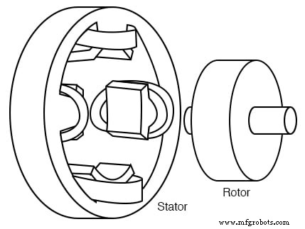
特斯拉多相感应电机
上图中的定子缠绕有与可用电能相位相对应的成对线圈。上面的两相感应电机定子有2对线圈,交流两相各一对。
一对中的单个线圈串联连接并对应于电磁体的相反极。也就是说,一个线圈对应一个 N 极,另一个对应一个 S 极,直到 AC 的相位改变极性。另一对线圈在空间上与第一对成 90°。
在两相电机的情况下,这对线圈连接到时间偏移 90° 的交流电。在特斯拉时代,两相交流的电源是两相交流发电机。
上图中的定子有凸极 ,明显的凸极,用于特斯拉早期的感应电机。时至今日,这种设计仍用于亚分数马力电机(<50 瓦)。然而,对于较大的电机,如果将线圈嵌入到定子叠片的槽中(下图),则会产生更小的转矩脉动和更高的效率。
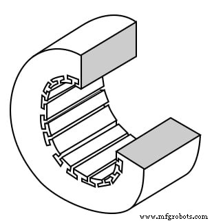
定子框架显示绕组槽
定子叠片是薄绝缘环,带有由电工钢片冲压而成的槽。一叠这些由端部螺钉固定,端部螺钉也可以固定端部外壳。

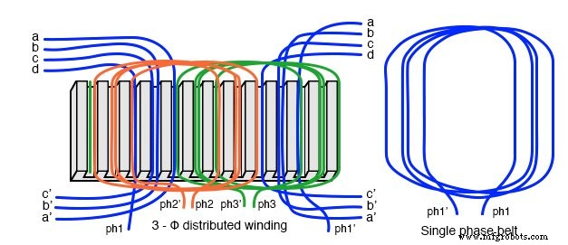
具有 (a) 2-φ 和 (b) 3-φ 绕组的定子
在上图中,两相电机和三相电机的绕组都安装在定子槽中。线圈缠绕在外部夹具上,然后加工到槽中。线圈外围和槽之间的绝缘楔形防止磨损。
实际的定子绕组比上图中每极的单个绕组更复杂。 2-φ电机与特斯拉的凸极2-φ电机相比,线圈数是相同的。在实际的大型电机中,一个磁极绕组被分成相同的线圈,插入许多比上面更小的槽中。
这个组被称为相带 (见下图)。相位带的分布式线圈抵消了一些奇次谐波,在磁极上产生更正弦的磁场分布。这显示在同步电机部分。
杆边缘的槽可能比其他槽的匝数少。边缘槽可以包含来自两相的绕组。即相带重叠。
交流感应电机普及的关键在于它的简单性,简单的转子就证明了这一点(下图)。转子由轴、钢叠片转子和嵌入式铜或铝鼠笼组成 ,如图 (b) 所示,从转子上拆下。
与直流电机电枢相比,没有换向器。这消除了电刷、电弧、火花、石墨粉尘、电刷调整和更换以及换向器的重新加工。
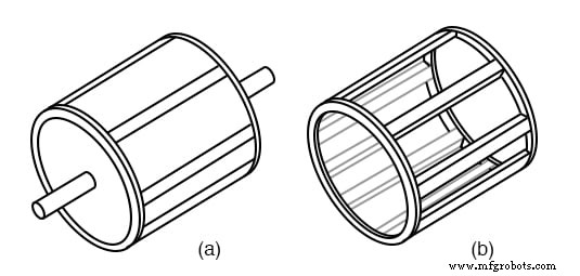
层压转子,带有 (a) 嵌入式鼠笼,(b) 从转子上拆下的导电笼
鼠笼式导体可以相对于轴倾斜、扭曲。与定子槽的错位减少了扭矩脉动。
转子和定子铁芯均由一叠绝缘叠片组成。叠片涂有绝缘氧化物或清漆,以最大限度地减少涡流损耗。叠片采用合金,磁滞损耗低。
感应电动机的工作原理
对操作的简短解释是定子产生旋转磁场,从而拖动转子。
感应电机的工作原理基于旋转磁场。产生旋转磁场的一种方法是旋转永磁体。如果移动的磁力线切割导电盘,它会跟随磁铁的运动。
切割导体的磁通线将在导电盘中感应出电压,并由此产生电流。这种电流流动产生了一个电磁体,其极性与永磁体的运动相反——楞次定律 .
电磁铁的极性使得它拉着永久磁铁。磁盘跟随的速度比永磁体慢一点。
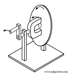
旋转磁场在导电盘中产生扭矩
圆盘产生的扭矩与切割圆盘的磁力线数量和切割圆盘的速率成正比。如果磁盘以与永磁体相同的速度旋转,则没有磁通切割磁盘,没有感应电流,没有电磁场,没有扭矩。
因此,磁盘的速度将始终落后于旋转的永磁体的速度,因此磁通线切割磁盘时会感应出电流,在磁盘中产生跟随永磁体的电磁场。
如果负载施加到磁盘上,使其减慢,随着更多磁通线切割磁盘,将产生更大的扭矩。扭矩与滑动成正比 ,圆盘落在旋转磁铁后面的程度。更多的滑差对应于更多的磁通切割导电盘,产生更大的扭矩。
模拟汽车涡流速度计基于上述原理。圆盘受弹簧约束,圆盘和针的偏转与磁铁转速成正比。
旋转磁场由彼此成直角放置的两个线圈产生,由异相 90° 的电流驱动。如果您熟悉示波器的 Lissajous 模式,这应该不足为奇。
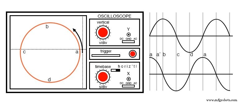
异相 (90°),正弦波产生圆形 Lissajous 图案
在上图中,通过用 90° 异相正弦波驱动水平和垂直示波器输入产生圆形 Lissajous。从(a)开始,最大“X”和最小“Y”偏转,轨迹向上和向左向(b)移动。
在 (a) 和 (b) 之间,两个波形在 45° 处等于 0.707 Vpk。该点 (0.707, 0.707) 落在 (a) 和 (b) 之间的圆的半径上 轨迹以最小“X”和最大“Y”偏转移动到 (b)。最大负“X”和最小“Y”偏转,轨迹移动到(c)。
然后以最小的“X”和最大的负“Y”移动到(d),然后返回到(a),完成一个循环。
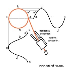
X 轴正弦和 Y 轴余弦轨迹圆
该图显示了两个 90° 相移正弦波应用于在空间中成直角的示波器偏转板。 90° 相位正弦波和直角偏转相结合,形成一个二维图案——一个圆。这个圆是由逆时针旋转的电子束描绘出来的。
作为参考,下图显示了为什么同相正弦波不会产生圆形图案。相等的“X”和“Y”偏转将照明点从 (a) 处的原点向上移动到 (b) 处的右侧 (1,1),从左下方返回到 (c) 处的原点,向左下方移动到 (-1) .-1) 在 (d) 处,然后直立回到原点。这条线是由沿两个轴的相等偏转产生的; y=x 是一条直线。
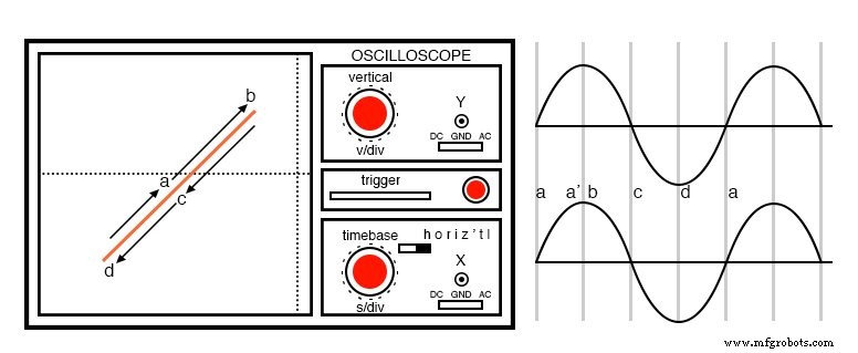
同相波形没有圆周运动
如果一对 90° 异相正弦波产生圆形 Lissajous,则一对类似的电流应该能够产生圆形旋转磁场。两相电机就是这种情况。以此类推,三个绕组在空间中相距 120°,并以相应的 120° 相电流馈送,也会产生旋转磁场。
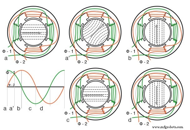
来自 90° 相位正弦波的旋转磁场
当上图的 90° 相位正弦波从 (a) 点到 (d) 点前进时,磁场逆时针旋转(图 a-d)如下:
- (a) φ-1 最大值,φ-2 零
- (a’) φ-1 70%, φ-2 70%
- (b) φ-1 零,φ-2 最大值
- (c) φ-1 最大负,φ-2 零
- (d) φ-1 零,φ-2 最大负
全电机转速和同步电机转速
定子旋转磁场的转速与每个定子相的极对数有关。下图的“全速”图一共有六极或三极对三相。然而,每相只有一个极对。
磁场将在每个正弦波周期旋转一次。在 60 Hz 功率的情况下,磁场以每秒 60 次或每分钟 3600 转 (rpm) 的速度旋转。对于 50 Hz 功率,它以每秒 50 转或 3000 rpm 的速度旋转。 3600 和 3000 rpm,是同步速度 电机。
虽然感应电机的转子从未达到这个速度,但它肯定是一个上限。如果我们将电机极数增加一倍,同步速度会减半,因为磁场在空间中旋转 180°,正弦电波 360°。
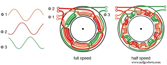
定子磁极加倍可使同步速度减半
同步速度由下式给出:
Ns =120·f/P Ns =同步速度,单位为 rpm f =施加功率的频率,Hz P =每相的总极数,2 的倍数
示例: 上面的“半速”图每相(三相)有四个极。 50Hz电源的同步转速为:S =120·50/4 =1500 rpm
感应电机的简单解释是定子产生的旋转磁场带动转子一起旋转。
更长更正确的解释是定子的磁场在转子鼠笼导体中感应出交流电,转子鼠笼导体构成了变压器次级。这种感应转子电流反过来又会产生磁场。
旋转定子磁场与该转子磁场相互作用。转子磁场试图与旋转定子磁场对齐。结果是鼠笼转子的旋转。如果没有机械电机转矩负载,没有轴承、风阻或其他损耗,转子将以同步速度旋转。
然而,滑动 转子和同步速度定子磁场之间产生转矩。正是磁通量在转子导体滑动时切割转子导体,从而产生扭矩。因此,负载电机将与机械负载成比例地滑动。
如果转子以同步速度运行,则没有定子磁通切割转子,转子中没有感应电流,没有转矩。
感应电机的扭矩
当电机首次通电时,转子处于静止状态,而定子磁场以同步速度 Ns 旋转。定子磁场以同步速度 Ns 切割转子。转子短路匝中感应的电流最大,电流频率,线频率也是如此。
随着转子加速,定子磁通切割转子的速率是同步速度 Ns 与实际转子速度 N 之间的差值,或 (Ns - N)。切割转子的实际磁通与同步速度之比定义为滑差 :
s =(Ns - N)/Ns 其中: Ns =同步速度,N =转子速度
感应到转子导体中的电流频率仅与电机启动时的线路频率一样高,随着转子接近同步速度而降低。 转子频率 由以下给出:
fr =s·f 其中:s =滑差,f =定子电源线频率
在感应电机中,100% 扭矩下的滑差通常为 5% 或更少。因此,对于 f =50 Hz 线路频率,转子中感应电流的频率 fr =0.05·50 =2.5 Hz。为什么这么低?定子磁场以 50 Hz 的频率旋转。转子转速降低5%。
旋转磁场仅以 2.5 Hz 的频率切割转子。 2.5 Hz 是同步速度和实际转子速度之间的差值。如果转子旋转得更快一点,在同步速度下,根本没有磁通切割转子,fr =0。
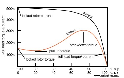
扭矩和速度与 %Slip。 %Ns=%同步速度
上图显示了启动转矩称为堵转转矩 (LRT) 高于 满载扭矩的 100% (FLT),安全连续扭矩额定值。对于上图中的示例电机,堵转转矩约为 FLT 的 175%。
启动电流称为堵转电流 (LRC) 是 满载电流的 500% (FLC),安全运行电流。电流很高,因为这类似于变压器上的次级短路。当转子开始旋转时,某些类型的电机的扭矩可能会降低到一个称为上拉扭矩的值 .
这是启动电机遇到的最低扭矩值。随着转子获得 80% 的同步速度,扭矩从满载扭矩的 175% 增加到 300%。这个击穿扭矩 是因为比正常滑差大了20%。
此时电流仅略有下降,但在此之后将迅速下降。当转子加速到同步速度的百分之几以内时,扭矩和电流都会大幅下降。正常运行时滑差只有几个百分点。
对于运行中的电机,扭矩曲线低于 100% 额定扭矩的任何部分都是正常的。电机负载决定了扭矩曲线上的工作点。虽然在启动过程中电机扭矩和电流可能会在几秒钟内超过 100%,但持续运行超过 100% 会损坏电机。
任何高于击穿扭矩的电机扭矩负载都会使电机失速。对于“无机械扭矩”负载条件,扭矩、滑差和电流将接近零。这种情况类似于开路的次级变压器。
有几种基本的感应电机设计与上面的扭矩曲线有很大差异。不同的设计针对启动和运行不同类型的负载进行了优化。各种电机设计和尺寸的堵转转矩 (LRT) 范围为满载转矩 (FLT) 的 60% 至 350%。
启动电流或堵转电流 (LRC) 的范围可以从满载电流 (FLC) 的 500% 到 1400%。这种电流消耗可能会给大型感应电机带来启动问题。
NEMA 和 IEC 电机等级
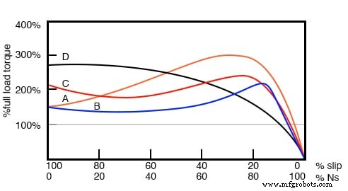
与扭矩曲线(下图)相对应的电机的各种标准等级(或设计)已被开发出来,以更好地驱动各种类型的负载。美国国家电气制造商协会 (NEMA) 指定了 A、B、C 和 D 类电机来满足这些驱动要求。
类似的国际电工委员会 (IEC) 等级 N 和 H 分别对应于 NEMA B 和 C 设计。
NEMA 设计的特征
除 D 类电机外,所有电机在满载时的滑差为 5% 或更低。
- B 类(IEC N 类) 电机是大多数应用中使用的默认电机。启动转矩为 LRT =FLT 的 150% 至 170%,它可以启动大多数负载,而不会产生过大的启动电流 (LRT)。效率和功率因数都很高。它通常驱动泵、风扇和机床。
- A级 启动转矩与B级相同。释放转矩和启动电流(LRT)更高。该电机可处理注塑机中遇到的瞬态过载。
- C 类(IEC H 类) 在 LRT =200% 的 FLT 时,具有比 A 级和 B 级更高的启动扭矩。该电机适用于需要恒速驱动的硬启动负载,如输送机、破碎机、往复泵和压缩机。
- D级 由于高滑差(FLT 为 5% 到 13%),电机具有最高的启动转矩 (LRT) 和低启动电流。高滑差导致较低的速度。调速不好。然而,该电机擅长驱动高变速负载,例如需要储能飞轮的负载。应用包括冲床、剪板机和升降机。
- E级 电机是 B 类的更高效率版本。
- F 级 电机的 LRC、LRT 和击穿扭矩比 B 级低得多。它们驱动恒定且易于启动的负载。
感应电机的功率因数
感应电机对电源线存在滞后(感应)功率因数。大型满载高速电机的功率因数可高达大型高速电机的90%。 3/4满载时,高速电机最大功率因数可达92%。
小型低速电机的功率因数可低至50%。启动时,功率因数可在10%~25%范围内,随着转子达到转速而上升。
功率因数 (PF) 随电机机械负载变化很大(下图)。空载电机类似于次级没有电阻负载的变压器。从次级(转子)反射到初级(定子)的阻力很小。
因此,电力线会遇到无功负载,PF 低至 10%。随着转子加载,增加的电阻分量从转子反射到定子,增加了功率因数。
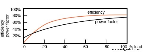
感应电机功率因数和效率
感应电机的效率
大型三相电机比小型三相电机和大多数单相电机效率更高。大型感应电机在满载时的效率可高达 95%,但更常见的是 90%。
轻载或空载感应电机的效率很低,因为大部分电流都与维持磁通量有关。随着扭矩负载的增加,产生扭矩时消耗更多的电流,而与磁化相关的电流保持固定。 75% FLT 时的效率略高于 100% FLT 时的效率。
效率在 50% FLT 时降低几个百分点,在 25% FLT 时降低几个百分点。效率只会在低于 25% FLT 时变差。效率随负载的变化如上图所示。
感应电机通常尺寸过大,以确保它们的机械负载可以在所有操作条件下启动和驱动。如果多相电机的负载低于额定扭矩的 75%,此时效率达到峰值,效率仅会略微下降至 25% FLT。
Nola 功率因数校正器
美国宇航局的弗兰克诺拉在 1970 年代后期提出了功率因数校正器(PFC)作为单相感应电机的节能装置。它基于这样一个前提,即低于满载的感应电机效率较低,并且功率因数低于满载电机。因此,在部分负载的电机,特别是1-φ电机中可以节省能源。
维持定子磁场所消耗的能量相对于负载变化是相对固定的。虽然满载电机没有什么可节省的,但可以降低部分负载电机的电压以减少维持磁场所需的能量。
这将提高功率因数和效率。对于众所周知的低效单相电机而言,这是一个很好的概念。
这个概念不太适用于大型三相电机。由于它们的高效率 (90%+),没有多少能量可以节省。此外,效率为 95% 的电机在 50% 满载扭矩 (FLT) 时仍为 94%,在满载扭矩 (FLT) 时仍为 90%。
从 100% FLT 到 25% FLT 的潜在节能是效率差异 95% - 90% =5%。这不是满载瓦数的 5%,而是降低负载时瓦数的 5%。 The Nola power factor corrector might be applicable to a 3-phase motor which idles most of the time (below 25% FLT), like a punch press.
The payback period for the expensive electronic controller has been estimated to be unattractive for most applications. Though, it might be economical as part of an electronic motor starter or speed Control.
Induction Motors as Alternators
An induction motor may function as an alternator if it is driven by a torque at greater than 100% of the synchronous speed (figure below). This corresponds to a few % of “negative” slip, say -1% slip.
This means that as we are rotating the motor faster than the synchronous speed, the rotor is advancing 1% faster than the stator rotating magnetic field. It normally lags by 1% in a motor. Since the rotor is cutting the stator magnetic field in the opposite direction (leading), the rotor induces a voltage into the stator feeding electrical energy back into the power line.
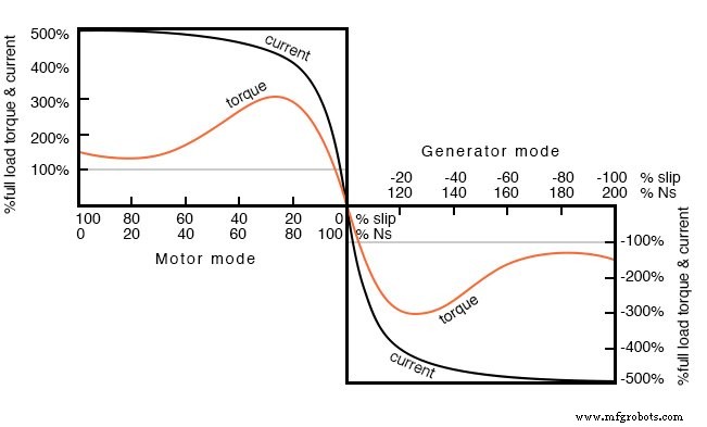
Negative torque makes induction motor into a generator
Such an induction generator must be excited by a “live” source of 50 or 60 Hz power. No power can be generated in the event of a power company power failure. This type of alternator appears to be unsuited as a standby power source.
As an auxiliary power wind turbine generator, it has the advantage of not requiring an automatic power failure disconnect switch to protect repair crews.
It is fail-safe.
Small remote (from the power grid) installations may be made self-exciting by placing capacitors in parallel with the stator phases. If the load is removed residual magnetism may generate a small amount of current flow.
This current is allowed to flow by the capacitors without dissipating power. As the generator is brought up to full speed, the current flow increases to supply a magnetizing current to the stator. The load may be applied at this point. Voltage regulation is poor. An induction motor may be converted to a self-excited generator by the addition of capacitors.
Startup procedure is to bring the wind turbine up to speed in motor mode by application of normal power line voltage to the stator. Any wind-induced turbine speed in excess of synchronous speed will develop negative torque, feeding power back into the power line, reversing the normal direction of the electric kilowatt-hour meter.
Whereas an induction motor presents a lagging power factor to the power line, an induction alternator presents a leading power factor. Induction generators are not widely used in conventional power plants.
The speed of the steam turbine drive is steady and controllable as required by synchronous alternators. Synchronous alternators are also more efficient.
The speed of a wind turbine is difficult to control and subject to wind speed variation by gusts. An induction alternator is better able to cope with these variations due to the inherent slip. This stresses the gear train and mechanical components less than a synchronous generator.
However, this allowable speed variation only amounts to about 1%. Thus, a direct line connected induction generator is considered to be fixed-speed in a wind turbine (See Doubly-fed induction generator for a true variable speed alternator).
Multiple generators or multiple windings on a common shaft may be switched to provide a high and low speed to accommodate variable wind conditions.
Motor Starting and Speed Control
Some induction motors can draw over 1000% of full load current during starting; though, a few hundred percents is more common. Small motors of a few kilowatts or smaller can be started by direct connection to the power line.
Starting large motors can cause line voltage sag, affecting other loads. Motor-start rated circuit breakers (analogous to slow blow fuses) should replace standard circuit breakers for starting motors of a few kilowatts. This breaker accepts high overcurrent for the duration of starting.
Autotransformer induction motor starter
Motors over 50 kW use motor starters to reduce line current from several hundred to a few hundred percents of full load current. An intermittent duty autotransformer may reduce the stator voltage for a fraction of a minute during the start interval, followed by application of full line voltage as in the figure above.
Closure of the S contacts applies reduced voltage during the start interval. The S contacts open and the R contacts close after starting. This reduces starting current to, say, 200% of full load current. Since the autotransformer is only used for the short start interval, it may be sized considerably smaller than a continuous-duty unit.
Running Three-Phase Motors on Single-Phase Provisions
Three-phase motors will run on single phase as readily as single-phase motors. The only problem for either motor is starting. Sometimes 3-phase motors are purchased for use on single-phase if three-phase provisioning is anticipated.
The power rating needs to be 50% larger than for a comparable single phase motor to make up for one unused winding. Single-phase is applied to a pair of windings simultaneous with a start capacitor in series with the third winding.
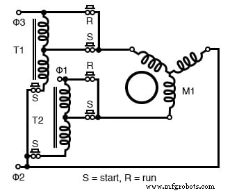
The start switch is opened in the figure below upon motor start. Sometimes a smaller capacitor than the start capacitor is retained while running.
Starting a three-phase motor on single phase
The circuit in the figure above for running a three-phase motor on single phase is known as a static phase converter if the motor shaft is not loaded. Moreover, the motor acts as a 3-phase generator.
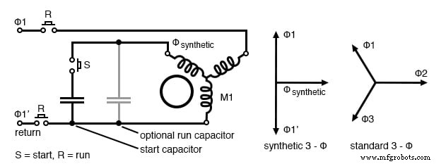
Three-phase power may be tapped off from the three stator windings for powering other 3-phase equipment. The capacitor supplies a synthetic phase approximately midway ∠90° between the ∠180° single-phase power source terminals for starting.
While running, the motor generates approximately standard 3-φ, as shown above. Matt Isserstedt shows a complete design for powering a home machine shop.
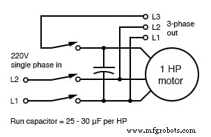
Self-starting static phase converter. Run capacitor =25-30µF per HP. Adapted from Figure 7, Hanrahan
Since a static phase converter has no torque load, it may be started with a capacitor considerably smaller than a normal start capacitor. If it is small enough, it may be left in the circuit as a run-capacitor (See the figure above).
However, smaller run-capacitors result in better 3-phase power output. Moreover, adjustment of these capacitors to equalize the currents as measured in the three phases results in the most efficient machine. However, a large start capacitor is required for about a second to quickly start the converter. Hanrahan provides construction details.
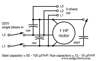
More efficient static phase converter. Start capacitor =50-100µF/HP. Run capacitors =12-16µF/HP. Adapted from Figure 1, Hanrahan
Induction Motors with Multiple Fields
Induction motors may contain multiple field windings, for example, a 4-pole and an 8-pole winding corresponding to 1800 and 900 rpm synchronous speeds. Energizing one field or the other is less complex than rewiring the stator coils.
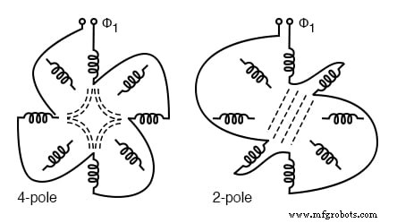
Multiple fields allow speed change
If the field is segmented with leads brought out, it may be rewired (or switched) from 4-pole to 2-pole as shown above for a 2-phase motor. The 22.5° segments are switchable to 45° segments. Only the wiring for one phase is shown above for clarity.
Thus, our induction motor may run at multiple speeds. When switching the above 60 Hz motor from 4 poles to 2 poles the synchronous speed increases from 1800 rpm to 3600 rpm.
Q: If the motor is driven by 50 Hz, what would be the corresponding 4-pole and 2-pole synchronous speeds?
A:
Ns =120f/P =120*50/4 =1500 rpm (4-pole) Ns =3000 rpm (2-pole)
Induction Motors with Variable Voltage
The speed of small squirrel cage induction motors for applications such as driving fans may be changed by reducing the line voltage. This reduces the torque available to the load which reduces the speed (see figure below).
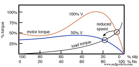
Variable voltage controls induction motor speed
Electronic Speed Control in Induction Motors
Modern solid-state electronics increase the options for speed control. By changing the 50 or 60 Hz line frequency to higher or lower values, the synchronous speed of the motor may be changed. However, decreasing the frequency of the current fed to the motor also decreases reactance XL which increases the stator current.
This may cause the stator magnetic circuit to saturate with disastrous results. In practice, the voltage to the motor needs to be decreased when the frequency is decreased.
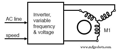
Electronic variable speed drive
Conversely, the drive frequency may be increased to increase the synchronous speed of the motor. However, the voltage needs to be increased to overcome increasing reactance to keep current up to a normal value and maintain torque.
The inverter approximates sine waves to the motor with pulse width modulation outputs. This is a chopped waveform which is either on or off, high or low, the percentage of “on” time corresponds to the instantaneous sine wave voltage.
Once electronics is applied to induction motor control, many control methods are available, varying from the simple to complex:
- Scalar Control: Low-cost method described above to control only voltage and frequency, without feedback.
- Vector Control: Also known as a vector phase control. The flux and torque producing components of stator current are measured or estimated on a real-time basis to enhance the motor torque-speed curve. This is computation intensive.
- Direct Torque Control: An elaborate adaptive motor model allows more direct control of flux and torque without feedback. This method quickly responds to load changes.
Tesla Polyphase Induction Motors Summary
- A polyphase induction motor consists of a polyphase winding embedded in a laminated stator and a conductive squirrel-cage embedded in a laminated rotor.
- Three-phase currents flowing within the stator create a rotating magnetic field which induces a current and consequent magnetic field in the rotor. Rotor torque is developed as the rotor slips a little behind the rotating stator field.
- Unlike single-phase motors, polyphase induction motors are self-starting.
- Motor starters minimize loading of the power line while providing a larger starting torque than required during running. Line current reducing starters are only required for large motors.
- Three-phase motors will run on single phase if started.
- A static phase converter is a three-phase motor running on single phase having no shaft load, generating a 3-phase output.
- Multiple field windings can be rewired for multiple discrete motor speeds by changing the number of poles.
Linear Induction Motors
The wound stator and the squirrel cage rotor of an induction motor may be cut at the circumference and unrolled into a linear induction motor. The direction of linear travel is controlled by the sequence of the drive to the stator phases.
The linear induction motor has been proposed as a drive for high-speed passenger trains. Up to this point, the linear induction motor with the accompanying magnetic repulsion levitation system required for a smooth ride has been too costly for all but experimental installations.
However, the linear induction motor is scheduled to replace steam-driven catapult aircraft launch systems on the next generation of the naval aircraft carrier, CVNX-1, in 2013. This will increase efficiency and reduce maintenance.
相关工作表:
- AC Motor Theory Worksheet
工业技术