

什么是步进电机?类型、构造、操作和应用
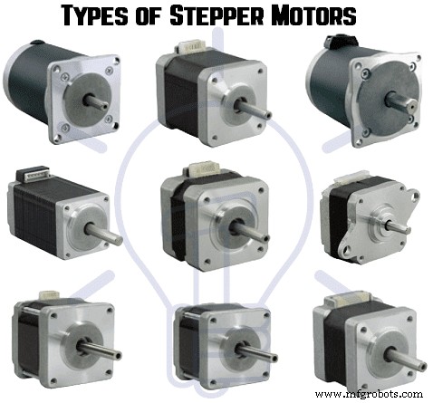
步进电机的类型——它们的构造、工作操作和应用
发明了专用的步进电机驱动卡和其他用于连接步进电机的数字控制技术 到基于 PC 的系统是最近步进电机被广泛接受的原因。步进电机成为需要精确速度控制或精确定位或两者兼有的自动化系统的理想选择。
众所周知,很多工业电机都采用闭环反馈控制来实现精准定位或精准调速,而另一方面,步进电机能够在一个开环控制器。与伺服系统控制相比,这反过来又降低了系统总成本并简化了机器设计。让我们简要讨论一下步进电机及其类型 . 
- 相关文章:伺服电机 - 类型、构造、工作和应用
什么是步进电机?
步进电机 是一种无刷机电设备,可将施加在励磁绕组上的电脉冲序列转换为精确定义的逐步机械轴旋转。对于每个离散脉冲,电机的轴旋转一个固定的角度。这种旋转可以是线性的,也可以是角度的。对于单个脉冲输入,它会移动一步。
当应用一系列脉冲时,它会转过某个角度。每个脉冲步进电机转轴所经过的角度称为步距角,一般用度数表示。
输入给电机的脉冲数决定了步进角,因此通过控制脉冲数来控制电机轴的位置。这种独特的特性使步进电机非常适合开环控制系统,其中轴的精确位置通过精确的脉冲数保持,而无需使用反馈传感器。
步距角越小,每转的步数越大,获得的位置精度越高。步距角大到90度,小到0.72度,常用的步距角有1.8度、2.5度、7.5度和15度。
轴旋转方向取决于施加在定子上的脉冲序列。轴的速度或平均电机速度与施加在励磁绕组上的输入脉冲的频率(输入脉冲的速率)成正比。因此,如果频率低,步进电机是分步转动的,而对于高频率,由于惯性,它像直流电机一样连续转动。
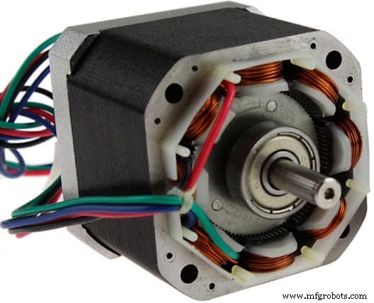
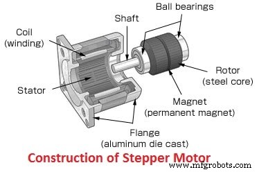
像所有电动机一样,它有定子和转子。转子是没有绕组、电刷和换向器的可动部件。通常转子是可变磁阻或永磁体。定子通常由多极和多相绕组构成,通常由三相或四相绕组组成,所需的极数由每个输入脉冲所需的角位移决定。
与其他电机不同的是,它使用经过编程的离散控制脉冲运行,这些脉冲通过电子驱动器施加到定子绕组。旋转是由于顺序通电的定子绕组磁极与转子磁极之间的磁相互作用而发生的。
有几种类型的步进电机 当今市场上有各种尺寸、步数、结构、接线、传动装置和其他电气特性。由于这些电机能够以离散方式运行,因此非常适合与计算机等数字控制设备连接。
由于对速度、旋转、方向和角度位置的精确控制,这些在工业过程控制系统、CNC 机器、机器人、制造自动化系统和仪器仪表。
- 相关文章:无刷直流电机 – 结构、工作原理和应用
步进电机的种类
有三种基本的步进电机类别 ,即
- 永磁步进电机
- 可变磁阻步进电机
- 混合式步进电机
在所有这些电机中,励磁绕组都用于定子,绕组数是指相数。
直流电压作为激励施加到绕组线圈,每个绕组端子通过固态开关连接到电源。根据步进电机的类型,其转子设计有带凸极的软钢转子、圆柱形永磁转子和带软钢齿的永磁。让我们详细讨论这些类型。
- 您还可以阅读:三相电机连接星形/三角 (Y-Δ) 反向/正向与定时器电源和控制图
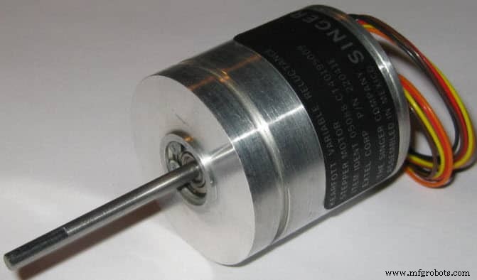
可变磁阻步进电机
它是步进电机的基本类型 它已经存在了很长时间,它确保了从结构的角度理解操作原理的最简单方法。顾名思义,转子的角位置取决于定子磁极(齿)和转子齿之间形成的磁路的磁阻。
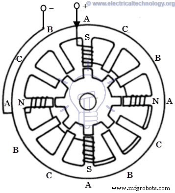
可变磁阻步进电机的构造
它由绕线定子和软铁多齿转子组成。定子有一堆硅钢叠片,定子绕组缠绕在这些叠片上。通常为三相绕制,分布在极对之间。
这样形成的定子极数等于定子上绕制绕组的相数的偶数倍。在下图中,定子有 12 个等距突出的磁极,每个磁极都绕有一个励磁线圈。这三相在固态开关的帮助下由直流电源供电。
转子不带绕组,为凸极型,完全由开槽钢叠片制成。转子磁极的凸齿与定子齿的宽度相同。定子极数与转子极数不同,提供了电机自启动和双向旋转的能力。
三相步进电机的转子磁极与定子磁极的关系为 Nr =Ns ± (Ns / q)。这里 Ns =12,q=3,因此 Nr =12 ± (12 / 3) =16 或 8。下图是一个没有任何励磁的 8 极结构转子。
可变磁阻步进电机的工作原理
步进电机工作原理 转子在磁路中与励磁极的齿对齐的特定位置,其中存在最小磁阻路径。每当电机通电并通过激励特定绕组时,它就会产生磁场并产生自己的磁极。
由于转子磁极的剩磁,会导致转子移动到这样的位置,以达到最小磁阻位置,从而实现转子的一组磁极与定子的通电磁极组对齐。在这个位置,定子磁场的轴线与通过转子任意两个磁极的轴线相匹配。
当转子与定子磁极对齐时,它有足够的磁力来保持轴顺时针或逆时针方向移动到下一个位置。
考虑下图所示为3相6定子4转子齿的示意图。当通过闭合开关 -1 为 A-A' 相提供直流电源时,绕组变成磁铁,导致一个齿变为北,另一个齿变为南。所以定子磁轴沿着这些磁极。
由于吸引力,定子线圈北极吸引最近的相反极性的转子齿,即南极和南极吸引最近的相反极性的转子齿,即北极。然后转子调整到转子磁轴与定子磁轴完全匹配的最小磁阻位置。
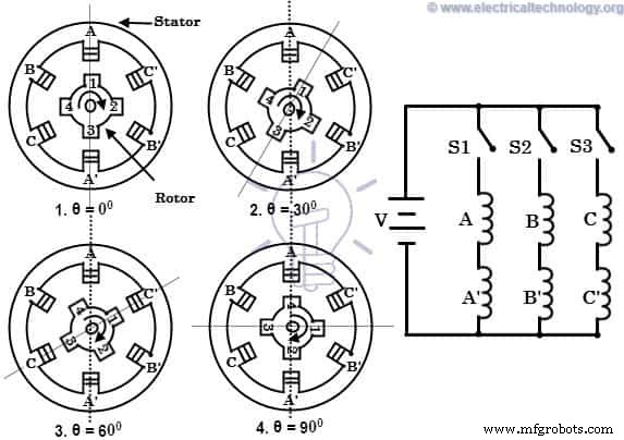
当 B-B' 相通电时闭合开关 -2 通过断开开关 -1 保持 A-A' 相保持断电,绕组 B-B' 将产生磁通量,因此定子磁轴沿由此形成的磁极移动。因此,转子通过磁化定子齿移动到最小磁阻,并沿顺时针方向旋转 30 度角。
打开switch-2后,当switch-3通电时,C-C'相通电,转子齿通过额外的30度角对准新位置度。通过这种方式,通过以特定顺序连续激励定子绕组,转子顺时针或逆时针方向移动。该三相四极转子齿步进电机的步距角表示为,360/(4×3)=30度(步距角=360/Nr×q)。
通过增加定子和转子上的极数可以进一步减小步距角,在这种情况下,电机通常会缠绕额外的相绕组。这也可以通过采用不同的步进电机结构来实现 如多叠排列和减速齿轮机构。
- 您还可以阅读:三相电机连接 STAR/DELTA 无定时器电源和控制图
永磁步进电机
永磁设计电机可能是几种步进电机中最常见的。顾名思义,它在电机结构中添加了永磁体。这种类型的步进电机也被称为can-stack motor 或锡罐电机 .这种电机的主要优点是制造成本低。这种电机每转48-24步。
建筑永磁步进电机
在这种电机中,定子是多极的,其结构类似于上面讨论的可变磁阻步进电机。它由绕有定子线圈的开槽外围组成。它在开槽结构上有突出的极点,绕组可以是两相或三相或四相。
所有这些绕组的末端都被买断并通过驱动电路中的固态开关连接到直流励磁。
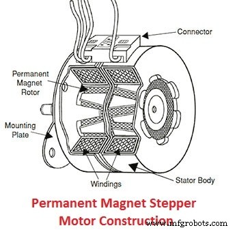
转子由永磁材料制成像铁氧体,可以是圆柱形或凸极的形状,但通常是光滑的圆柱形。转子设计为具有偶数个永磁极,南北极交替。
永磁步进电机工作原理
这种电机的工作原理是异极相吸,异极相斥。当定子绕组被直流电源激励时,它会产生磁通量并建立北极和南极。由于永磁转子磁极和定子磁极之间的吸引力和排斥力,转子开始向上移动到向定子提供脉冲的位置。
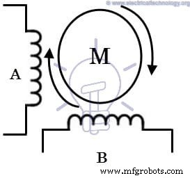
考虑一个具有两个永磁转子磁极的两相步进电机,如下图所示。
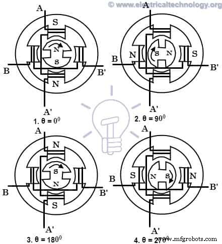
当 A 相用正极通电时相对于 A',绕组建立北极和南极。由于吸引力,转子磁极与定子磁极对齐,转子磁极轴与定子磁极轴调整如图所示。
当励磁切换到B相并关闭A相时,转子进一步调整到B相的磁轴,从而顺时针旋转90度。
接下来,如果 A 相通过相对于 A' 的负电流通电,定子磁极的形成会导致转子沿顺时针方向再移动 90 度。
同理,如果通过闭合A相开关使B相得到负电流励磁,则转子沿同一方向再旋转90度。接下来,如果 A 相被正电流激励,则转子回到初始位置,从而完成 360 度的完整旋转。这意味着,每当定子被激励时,转子往往会顺时针旋转 90 度。
这个2相2极永磁转子电机的步距角表示为,360/(2×2)=90度。步长可以通过同时激励两相或一系列具有适当极性的一相开和两相开模式来减小。
- 您还可以阅读:与电机控制和保护相关的术语和定义
混合式步进电机
它是最流行的步进电机类型 因为它在步进分辨率、保持转矩和速度方面提供了比永磁转子更好的性能。但是,这些电机比 PM 步进电机更昂贵。 It combines the best features of both variable reluctance and permanent magnet stepper motors. These motors are used in applications that require very small stepping angle such as 1.5, 1.8 and 2.5 degrees.
Construction of Hybrid Stepper Motor
The stator of this motor is same as its permanent magnet or reluctance type counterpart. The stator coils are wound on alternate poles. In this, the coils of different phases are wound on each pole, usually two coils at a pole which is referred as a bifilar connection.
The rotor consists of a permanent magnet which is magnetized in axial direction to create a pair of magnetic poles (N and S poles). Each pole is covered with uniformly spaced teeth. The teeth are made up of soft steel and two section, of which on each pole are misaligned each other by a half-tooth pitch.
- Related Post Why Electric Motors rated in kW instead of kVA?
Working of Hybrid Stepper Motor
This motor works similar to that of permanent magnet stepper motor. The figure above shows 2-phase, 4-pole, 6-tooth rotor hybrid stepper motor. When the phase A-A’ is excited with a DC supply, keeping B-B’ unexcited, the rotor aligns such that the south pole of the rotor faces north pole of the stator while north pole of rotor faces south pole of the stator.
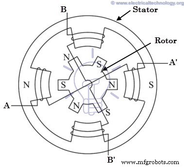
Now, if the phase B-B’ is excited, keeping A-A’ switched off in such a way that upper pole becomes north and lower becomes south, then the rotor will align to a new position by moving through counterclockwise direction. If the phase B-B’ is oppositely excited such that the upper pole becomes south and lower becomes north, then the rotor will turn clockwise direction.
By a proper sequence of pulses to the stator, the motor will turn in desired direction. For every excitation, rotor will get locked into new position, and even if excitation is removed motor still maintains its locked condition due to the permanent magnet excitation. The step angle of this 2-phase, 4-pole, 6-tooth rotor motor is given as 360/ (2 × 6) =30 degrees. In practice, hybrid motors are constructed with more number of rotor poles in order to get high angular resolution.
- Related Post:What is Motor Efficiency &How to improve it?
Unipolar and Bipolar Stepper Motors
The above discussed motors can be unipolar or bipolar based on the coil winding arrangements. A unipolar motor is employed with two windings per phase and hence the direction of current flow through these windings changes the rotation of the motor. In this configuration, the current flow is through one direction in one coil and opposite direction in another coil.
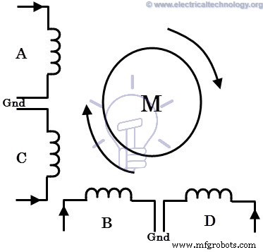
The figure below shows 2-phase unipolar stepper motor wherein A and C coils are for one phase and B and D are for other phase. In each phase each coil carries current in opposite direction to that of other coil. Only one coil will be carrying current at a time in each phase for achieving particular direction of rotation. So just by switching the terminals to each coil, the direction of rotation is controlled.
In case of a bipolar stepper motor, each phase consists of a single winding rather than two in case of unipolar one. In this, the direction of rotation is controlled by reversing the current through the windings. Hence, it requires a complex drive circuit for current reversal.
- You may also read:What is a Solenoid and Solenoid Magnetic Field
Stepping Modes of a Stepper Motor
A typical stepping action causes the motor to step through a sequence of equilibrium positions in response to current pulses given to it. It is possible to vary the stepping action in different ways simply by changing the sequence through which stator windings are energized. The following are the most common operating or driving modes of stepper motors.
- Wave step
- Full step
- Half step
- Microstepping
Wave Step Mode
Wave step mode is the simplest of all other modes in which only one winding is energized at any given time. Each coil of the phase is connected to the supply alternatively. The table below shows the order through which coils are energized in a 4-phase stepper motor.
In this mode motor gives maximum step angle compared to all other modes. It is the simplest and most commonly used mode for stepping; however the torque produced is less as it uses some part of the total winding at a given time. 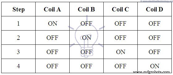
Full Step Mode
In this drive or mode, two stator phases are energized simultaneously at any given time. When two phases are energized together, the rotor will experience the torque from both phases and comes to the equilibrium position, which will be interleaved between two adjacent wave step positions or 1-phase excitations. So this step provides better holding torque than wave step. The table below shows the full step drive for 4-phase stepper motor. 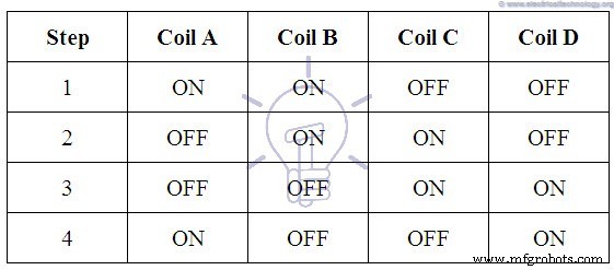
Half Step Mode
It is the combination of both wave and full step modes. In this, single phase and dual phase excitations are carried out alternatively, i.e., one-phase ON, two-phases ON, and so on. The step angle in this mode becomes half of the full step angle. This drive mode has highest torque and stability compared to all other modes. The table containing phase pulsing sequence for a 4-phase motor in half stepping is given below. 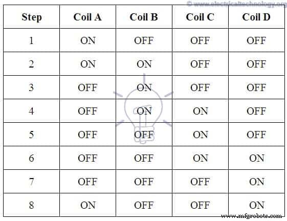
Microstepping Mode
In this mode, each motor step is subdivided into several small steps, even hundreds of fixed positions, therefore a greater positioning resolution is obtained. In this, currents through the windings are continually varied in order to get very small steps. In this, two phases are excited simultaneously, but with the unequal currents in each phase.
For example, the current through phase -1 is held constant while the current through phase-2 is incremented in steps till the maximum value of current, whether it is negative or positive. The current in the phase-1 is then decreased or increased in steps till zero. Thus, the motor will produce a small step size.
All these stepping modes can be obtained by each type of stepper motor discussed above. However, the direction of current in each winding during these steps can be varied depending on the type of motor and either it is unipolar or bipolar.
- Related Post Cable Size Calculation for LT &HT Motors
Advantages of Stepper Motor
- At standstill position, the motor has full torque. No matter if there is no moment or changing position.
- It has a good response to starting, stopping and reversing position.
- As there is no contact brushes in the stepper motor, It is reliable and the life expectancy depends on the bearings of the motor.
- The motor rotation angle is directly proportional to the input signals.
- It is simple and less costly to control as motor provides open loop control when responding to the digital input signals.
- The motor speed is directly proportional to the input pulses frequency, this way a wide range of rotational speed can be achieved.
- When load is coupled to the shaft, it is still possible to realize the synchronous rotation with low speed.
- The exact positioning and repeatability of movement is good as it has a 3-5% accuracy of a step where the error is non cumulative from one step to another.
- Stepper motors are safer and low cost (as compared to servo motors), having high torque at low speeds, high reliability with simple construction which operates at any environment.
Disadvantages of Stepper Motors
- Stepper motors having low Efficiency.
- It has low Accuracy.
- Its torque declines very quickly with speed.
- As stepper motor operates in open loop control, there is no feedback to indicate potential missed steps.
- It has low torque to inertia ratio means it can’t accelerate the load very quickly.
- They are noisy.
Applications of Stepper Motors
- Stepper motors are used in automated production equipments and automotive gauges and industrial machines like packaging, labeling, filling and cutting etc.
- It is widely used in security devices such as security &surveillance cameras.
- In medical industry, stepper motors are widely used in samples, digital dental photography, respirators, fluid pumps, blood analysis machinery and medical scanners etc.
- They are used in consumer electronics in image scanners, photo copier and printing machines and in digital camera for automatic zoom and focus functions and positions.
- Stepper motors also used in elevators, conveyor belts and lane diverters.
您还可以阅读:
- DC Drives – Construction, Working &Classification of Electrical DC Drives
- Three Phase Motor Power &Control Wiring Diagrams
- Electric Motors Library (AC &DC )
工业技术