

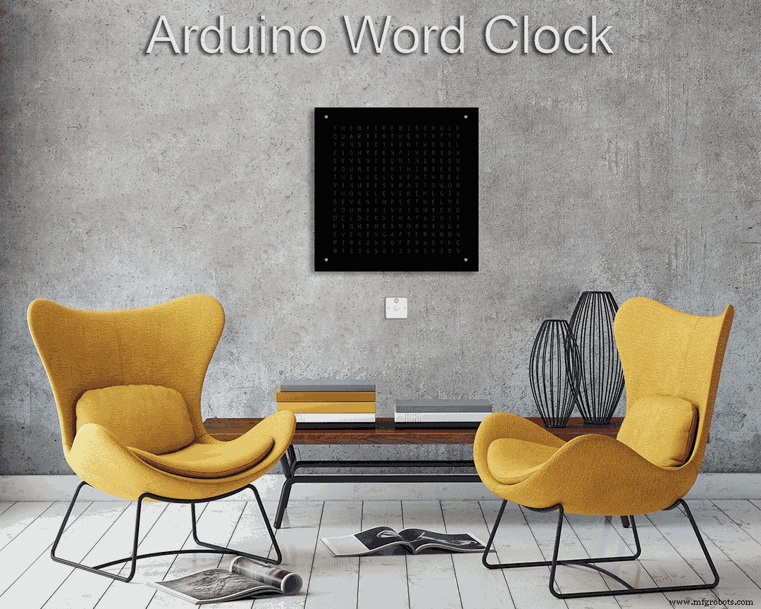
字时钟,以文字表示时间的分钟分辨率
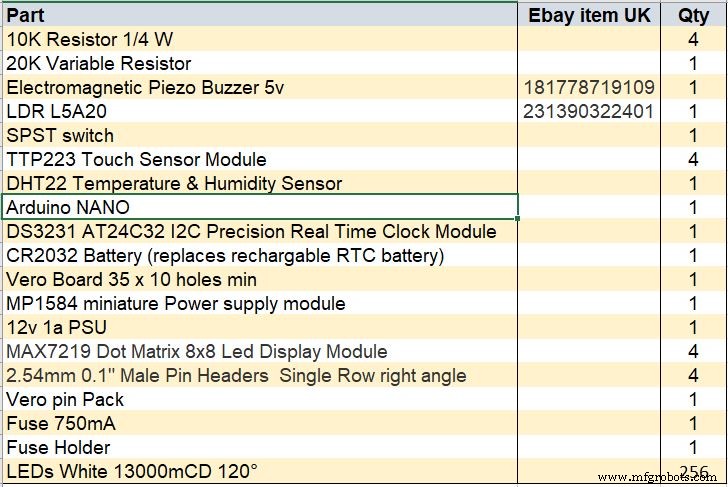
组件和用品
 |
| × | 1 |
关于这个项目
有关此版本的更多详细信息,请访问我的网站:Word Clock
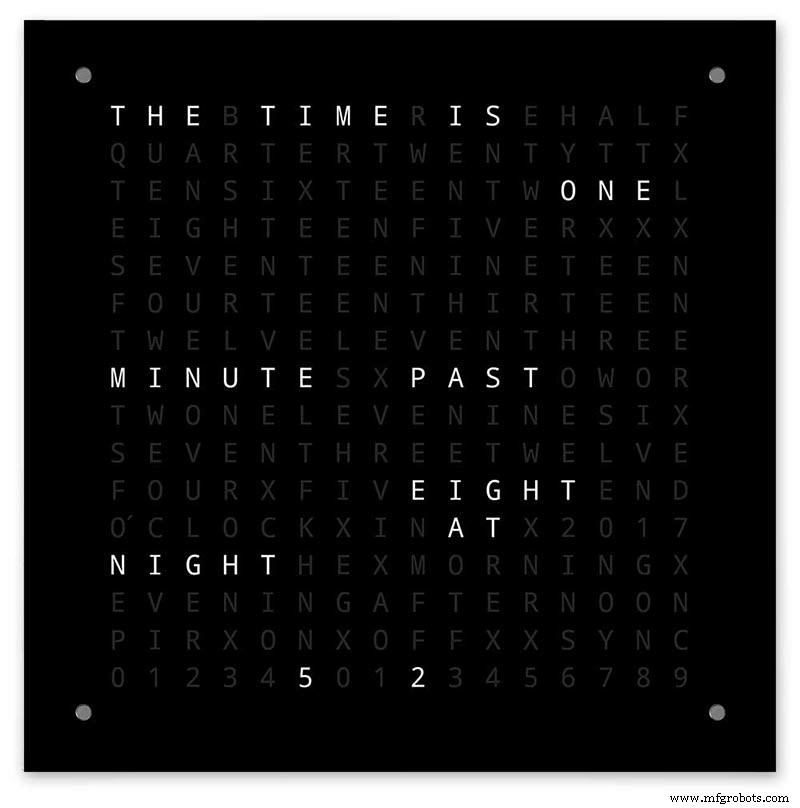
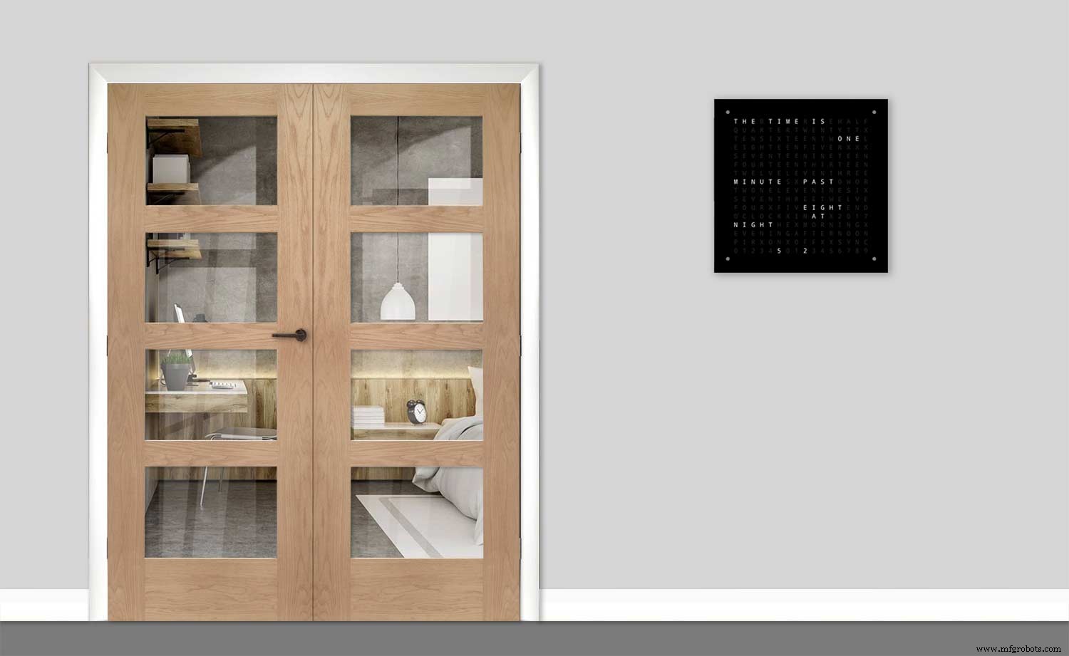
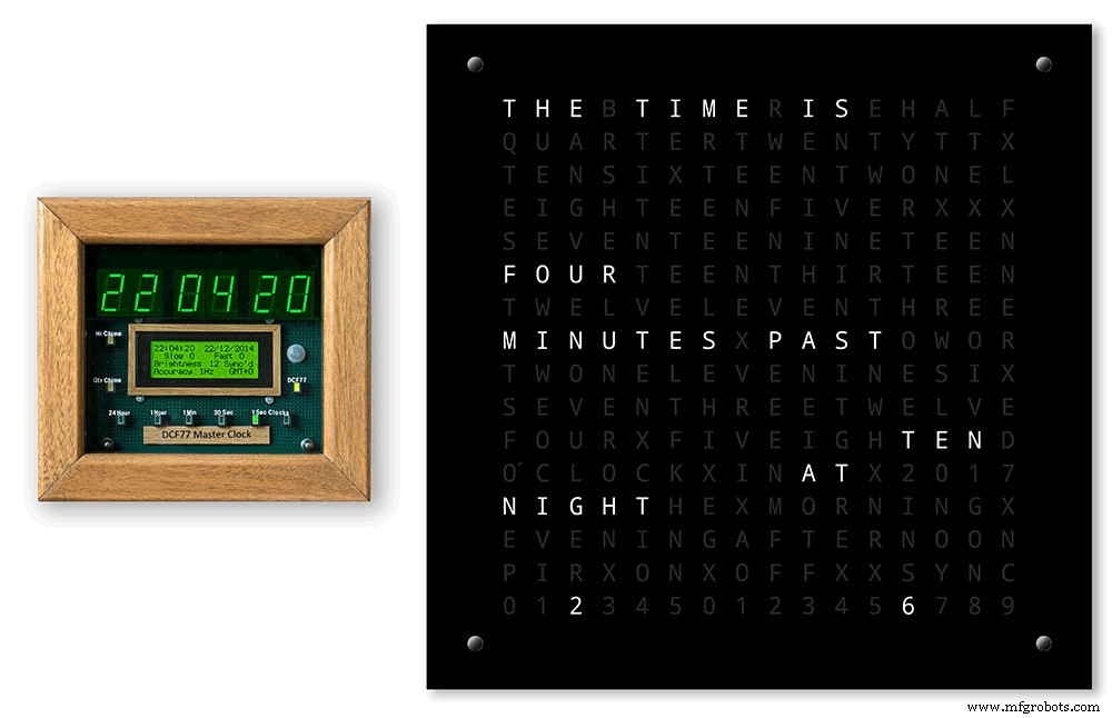
Arduino 字时钟,具有分钟的时间分辨率和秒的线性显示。
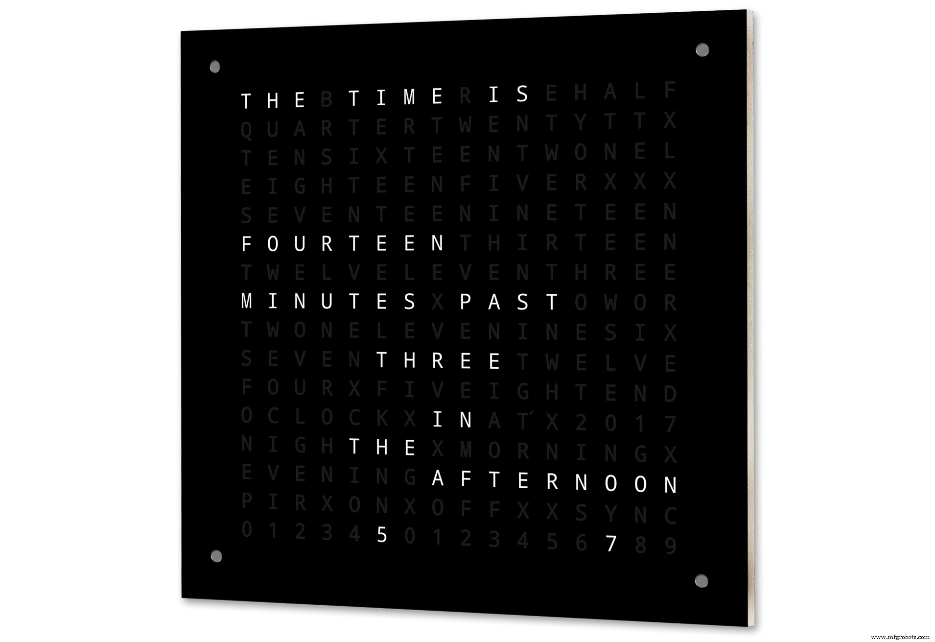
还有数字时钟、模拟时钟、温度和湿度的模式,以及三个游戏:生命游戏、西蒙和俄罗斯方块。
如果需要,时钟可以是独立的,也可以作为主时钟的从属时钟运行。
没有主时钟,时间由字时钟的内置温度补偿实时时钟控制。
有 PIR 或多普勒雷达控制选项,当房间内无人时时钟会自动关闭。
时钟尺寸为 500 毫米 x 500 毫米(19.68 英寸 x19.68 英寸),重 12 磅(5.5 公斤),设计为壁挂式。每个角落都有触摸板,可以设置和控制时钟。
第 1 步:关于字时钟
关于字时钟
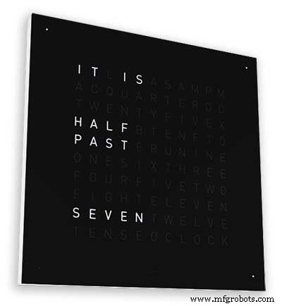
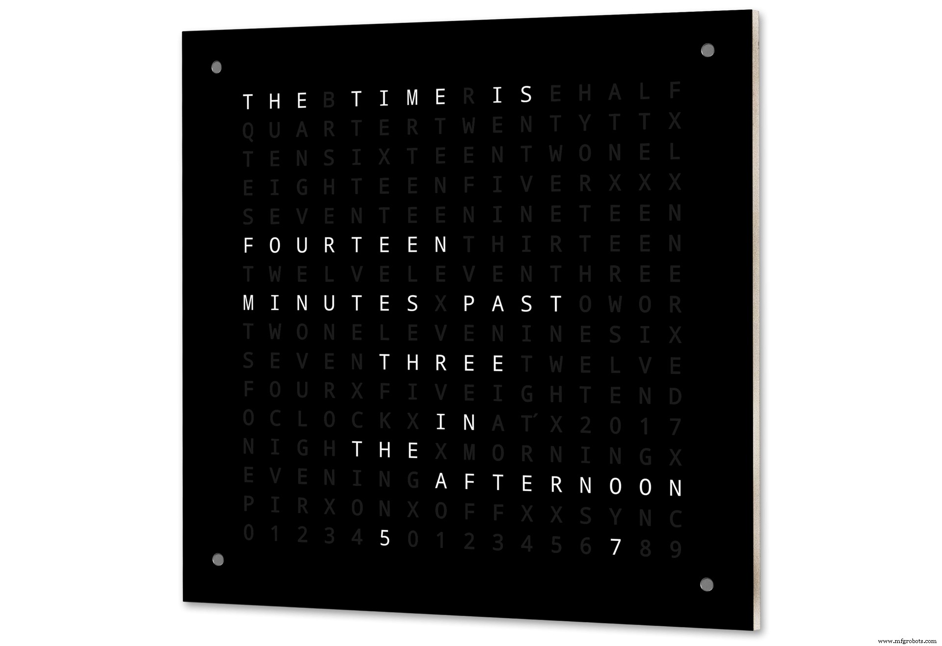
字钟使用由单词或数字和字母组成的矩阵来显示时间,并且已经存在多年。有几种不同的设计类型会影响时钟构建的复杂性。
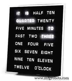
最简单的使用单词块来以五分钟的分辨率显示时间,例如 O'CLOCK、5 PAST、10 PAST 等。这些时钟仅使用 20 个左右的单独 LED 块,因此构造最简单。这些时钟的主要缺点是它们只能以这种设置格式显示时间。
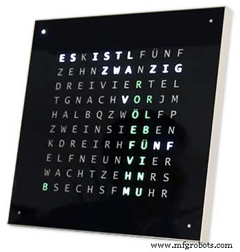
中级时钟有一个 11x10 的 LED 矩阵,时钟外部还有四个附加 LED。Raspberry Pi 控制的时钟照片 2 甚至还有多色 LED,因为它有 110 个单独的 LED,它可以显示数字和基本图像。这些时钟仍然使用文字的 5 分钟分辨率,但经常添加“刚过去 5 分钟”或几乎 10 分钟以稍微增加分辨率。通常框架四角周围的四个 LED 指示过去了四分钟以填补之间的空白5 分钟的文字分辨率。这些时钟的构建相当复杂,并且通常使用 LED 灯条使构建更容易。
这种类型的时钟有商业版本。450 毫米壁挂版本售价约 1000 英镑,具有多种颜色和材料的可互换前面板,以及更小的桌面和手表。
Wouter Devinck 的 256 矩阵字时钟
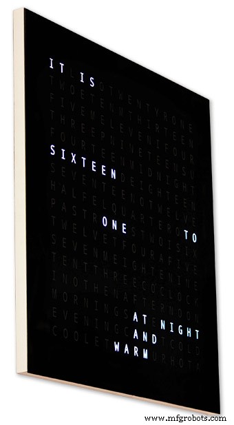
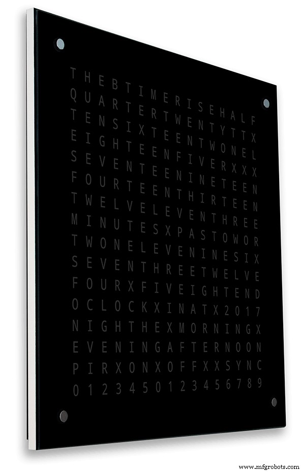
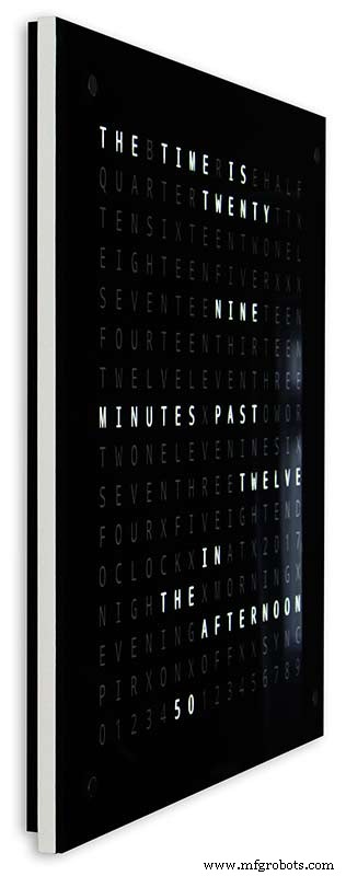
最复杂的字时钟使用 16x16 LED 矩阵,提供完整的 256 个 LED 来控制。这些时钟具有一分钟的时间分辨率以及早上、晚上、晚上等。它们经常用文字告诉粗略的温度如暖、非常暖、冷非常冷等
使用 256 个 LED 可以提供大量不同的显示模式。由于矩阵显示器中的连接数量众多,这些时钟的构建非常复杂。在带有表面贴装元件的 PCB 上构建 LED 矩阵可以实现非常纤薄的时钟体,并使显示结构更简单,但超过 500mm x 500mm 的 PCB 开始变得昂贵。
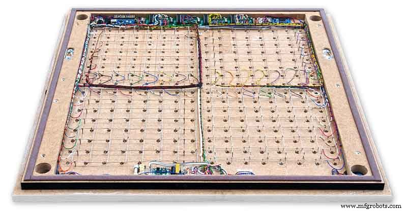
在我的时钟中手工构建 LED 矩阵需要空间,500mm x 500mm 是一个很好的起点,因为这几乎可以容纳互连 LED 和显示模块所需的大型布线织机。可以使用手工制作的 LED 矩阵制作非常大的壁挂钟。
第 2 步:更改
变化
该时钟是 Wouter Devinck 时钟硬件和“加泰罗尼亚”Pijuana 时钟软件的混合体。我没有使用任何 PCB 只是现成的模块和三个小型 Vero 电路板作为电源。
主要变化详述如下。
在这个版本的时钟中没有使用定制的 PCB,只是通过预先构建的模块很容易获得。
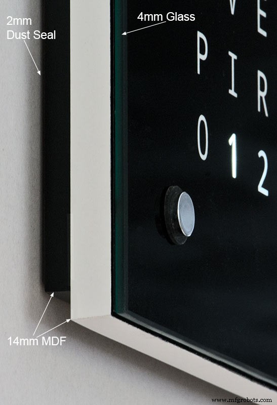
时钟主体由 2 x 14 毫米 MDF 板制成,而不是单张 18 毫米板。
除了顶部,后板比前板小 10 毫米,因此时钟看起来只有 14 毫米厚。
Wouter Devinck 时钟只有 20 毫米深,包括 2 毫米玻璃,而我的时钟实际上是 34 毫米深,包括 4 毫米玻璃和后部的 2 毫米防尘密封。由于后部 14 毫米面板的后退和玻璃面板的 1.5 毫米后退,从大多数角度来看,时钟看起来只有 14 毫米深。这种额外的深度使我能够使用手工制作的 LED 矩阵和布线织机,而不是 4 个大型 PCB。这也意味着我可以在 MAX7219 板上使用预建的易于维护的模块,无需表面贴装 IC。
主显示器直接内置于显示器 LED,没有 PCB,因此可以显示任何尺寸的显示器。使用 TTP223 触摸传感器模块代替安装在主板上的 Azoteq IQS127D。
MAX7219 I/C 的显示驱动板使用改进的 LED 矩阵板。这些电路板配备了所有组件。
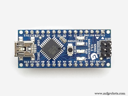
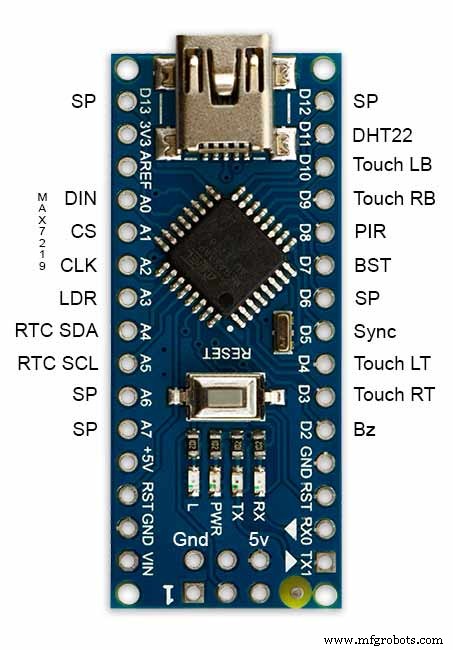
由于体积小,使用Arduino Nano驱动时钟。
PIR 传感器模块用于在房间内无人时关闭显示器(可以禁用该模块以保持显示器始终开启)。
电路中添加了一个微调电阻器,可从时钟底部使用小型平口螺丝刀访问,以校准自动显示亮度。
每分钟同步到我的主时钟系统 30 秒。如果没有可用的同步脉冲,时钟将使用 RTC 自由运行。同步脉冲显示在主显示器上。
该软件主要基于单词时钟的“加泰罗尼亚语”Pijuana 版本,因此已将其翻译成英文以供显示。 Credits 显示从“Catalan” Pijuana 版本修改而来,以显示当前软件版本号、我的名字以及构建年份。
已从时钟显示中删除了文字温度,并在字、数字和模拟时钟的底行添加了线性秒显示。
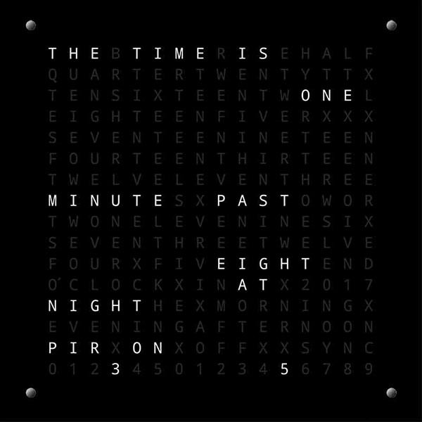
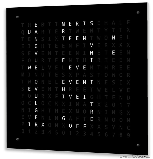
当 PIR 打开或关闭时,“PIR ON”或“PIR OFF”会在字时钟显示屏上显示几秒钟。
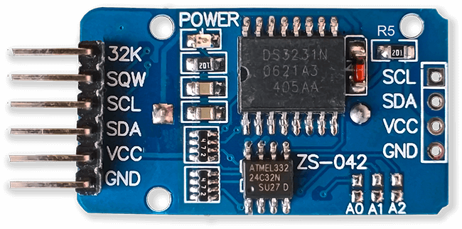
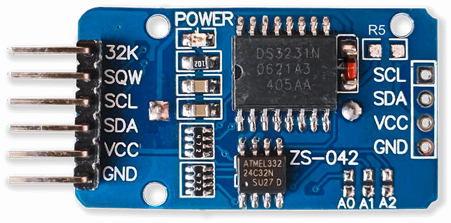
根据 Wouter Devinck 时钟和“加泰罗尼亚”Pijuana 时钟,该时钟使用 DS3231 AT24C32 I2C 精密实时时钟模块。我不喜欢使用随模块提供的锂离子充电电池。我使用的是非充电电池,并修改了模块以适应。
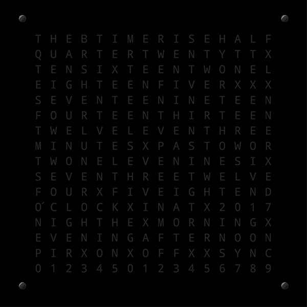
边缘抛光的 4 毫米浮法玻璃取代了 2 毫米玻璃。玻璃使用芝加哥紧固件而不是胶水固定在主 MDF 板上。它们还可以作为控制时钟的触摸板,并允许在需要时移除玻璃。
时钟内置了两个防尘密封件,一个在后面板上,一个在可拆卸的玻璃显示面板后面。在时钟设置模式下按 BOT 右按钮现在将秒重置为 0。
对英文措辞进行了以下更改,以使措辞如我所说。个人说时间的方式会因地区而异,具体取决于您居住/上学的地点等。没有正确的方式,只有最适合您的方式。
删除了字时钟上指示温度的字样。这些已被同步状态、PIR ON/OFF 和秒的线性显示所取代。
将过去 1 分钟和 1 分钟时的“分钟”更改为“分钟”。
在过去的“QUARTER”和小时的“QUARTER”之前添加了“A”。
根据他的笔记添加了 Wouter Devinck 时钟中缺失的“11”。
中午把时间改成下午十二点钟了。
在午夜改变了阅读午夜十二点的时间。午夜过后,时钟总是说在早上。
“O'CLOCK”现在没有标点符号,只显示 OCLOCK。
第 3 步:案例设计
由于我的时钟不使用带有表面贴装组件的定制显示矩阵 PCB,因此我的时钟外壳必须比 Wouter 的设计更深一些。
我的机箱深 34 毫米,包括 2 毫米的后防尘封、14 毫米的后中密度纤维板、14 毫米的前显示板和 4 毫米浮法玻璃。
Wouter 的右表壳只有 21 毫米深、18 毫米单中密度纤维板面板和 2 毫米浮法玻璃。
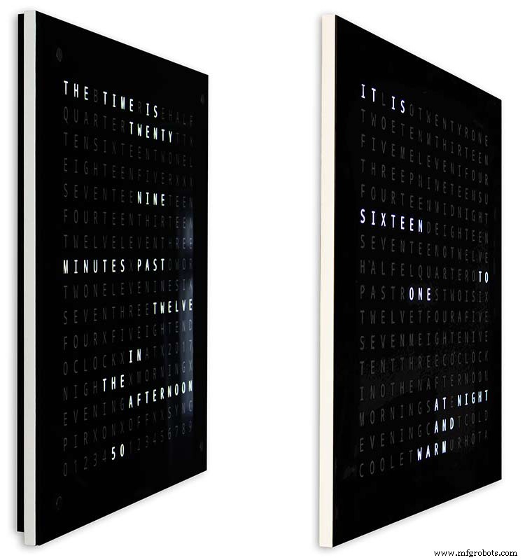
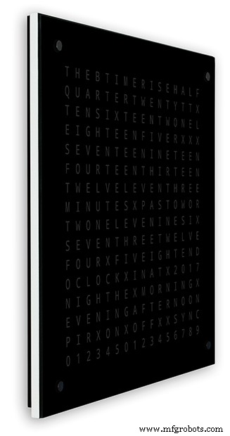
为了让我的时钟安装在墙上时看起来不那么笨重,我加入了一些简单的设计功能。上图左边是我的时钟,右边是 Wouter 的时钟。从极端的侧面角度来看,您可以清楚地看到我的箱子看起来更笨重。
这在一定程度上被后板为黑色而不是白色所抵消,使您的眼睛专注于纤细的白色 14 毫米边缘。后板底部短 10 毫米,两侧加强了这种错觉。
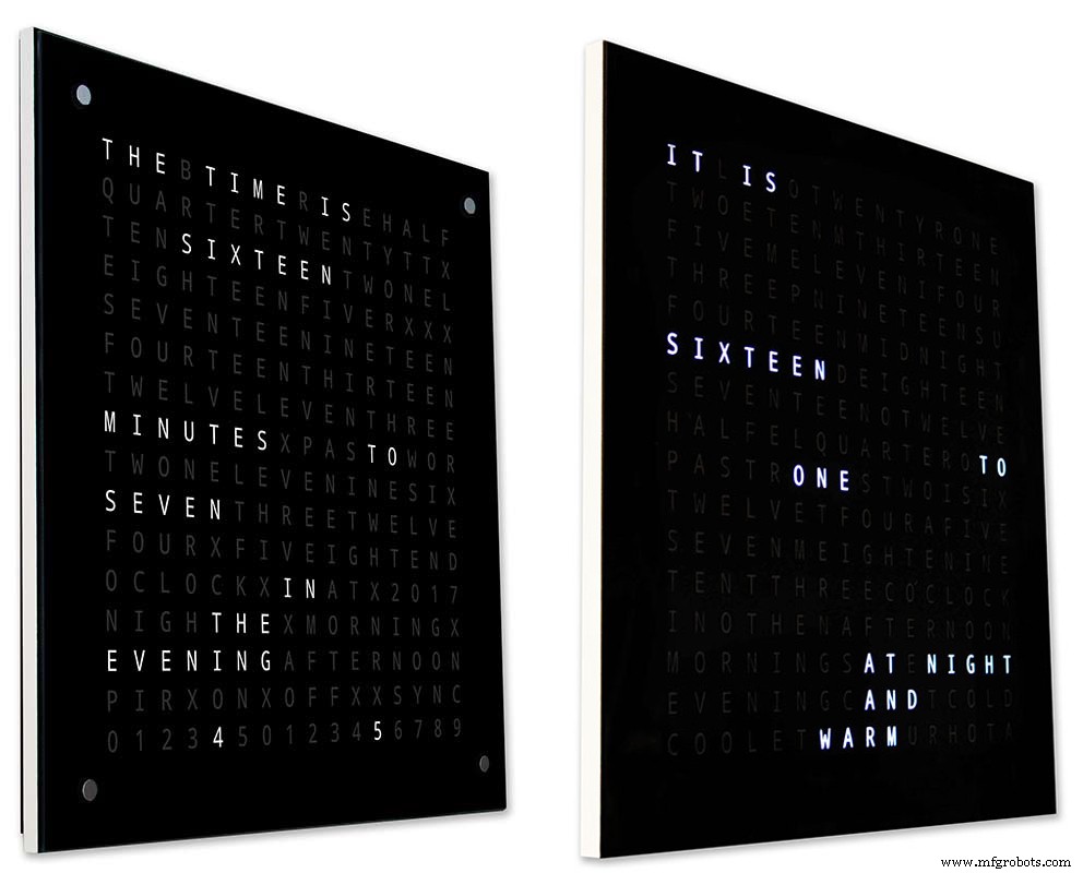
上面 - 左边是我的时钟,右边是 Wouter 的时钟。越靠近时钟的前部,我时钟上较短的后面板就会从视野中消失,直到只有纤薄的 14 毫米前面板可见。4 毫米玻璃也比前面板短 1-2 毫米,有助于将其隐藏起来.我笨重的 34 毫米时钟外壳现在看起来和 Wouter 的外壳一样纤薄。
第 4 步:控制
控制

时钟、显示屏左上角、右上角、左下角和右下角有TTP223触控模块。
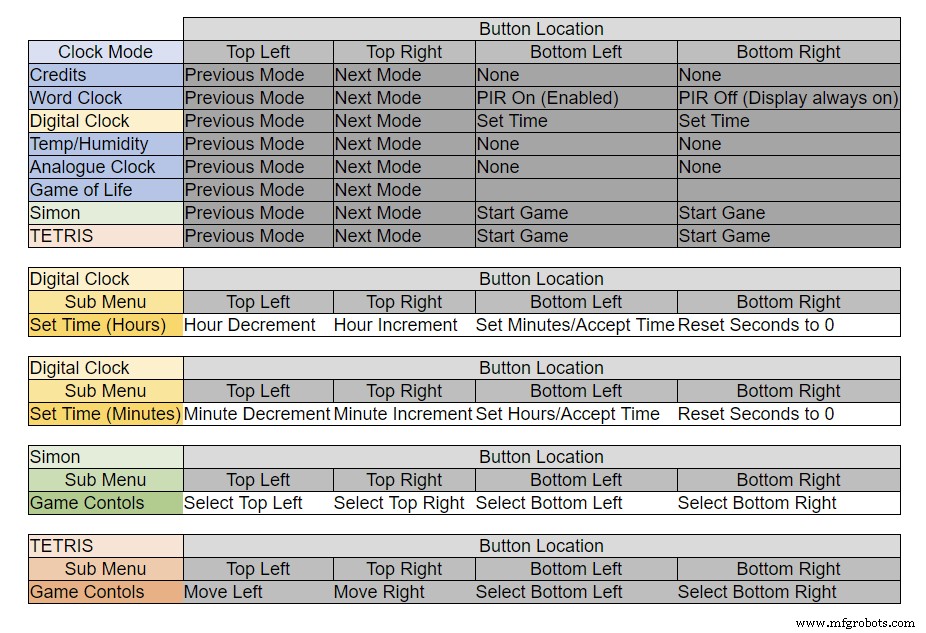
根据时钟所处的模式,按钮具有不同的功能,见上表。
第 5 步:自动夏季冬季设置
未使用。
第 6 步:显示模式时钟和环境
上面的动画 1 显示了 4 种时钟和环境模式。
模式依次为字时钟、数字时钟、温湿度、模拟时钟。
动画 2 以上。还有一种启动模式,可以在软件版本号、制造商名称和时钟名称之间滚动。
第 7 步:显示模式游戏
三个经典游戏被编码到时钟中。我保留了加泰罗尼亚时钟的代码。

康威生命游戏上方的动画 1。生命游戏的宇宙是一个无限的二维正交方格网格,每个方格都处于两种可能的状态中的一种,活或死,或“已填充”或“未填充”。
每个单元格与其八个相邻单元格相互作用,这些单元格是水平、垂直或对角相邻的单元格。在每一步,都会发生以下转变: 任何少于两个活邻居的活细胞都会死亡,就好像是由人口不足造成的。任何有两个或三个活邻居的活细胞都会传给下一代。任何拥有三个以上活邻居的活细胞都会死亡,就像人口过多一样。任何只有三个活邻居的死细胞都会变成活细胞,就像通过繁殖一样。
初始模式构成了系统的种子。第一代是通过将上述规则同时应用于种子中的每个细胞而创建的一)。规则不断重复应用以创造更多世代。
动画2上面西蒙
西蒙记忆游戏-尝试并复制计算机生成的序列。输入您的序列时,双击最后一个条目以结束您的回合。
当你失败时,你的分数会显示在屏幕上。
俄罗斯方块上方的动画 3 是 1984 年 6 月发布的苏联瓷砖匹配益智视频游戏。该游戏仍然需要在按钮上做一些工作才能正确控制瓷砖。
第 8 步:原型制作
时钟可以使用 MAX7219 显示板上的原始点阵 LED 进行原型设计和测试。
请注意,仅当您想在 MAX7219 模块提供的 DOT 矩阵显示器上测试您的代码时,才需要进行此临时修改。
这意味着您可以在提交全尺寸版本之前尝试微型软件/文字布局修改。必须修改点阵 LED 的接线以匹配软件连接。
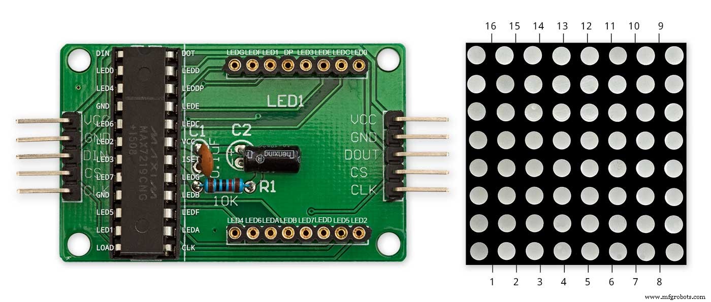
上图显示了模块在修改前的接线方式。修改非常简单。首先将以下LED矩阵引脚弯曲90°,顶部引脚向上,底部引脚向下。
引脚 16、15、3、4、10 和 11。
将 LED 矩阵插入显示 PCB 上的插座中,现在不会连接上述引脚。将以下链接线从显示 PCB 的插座背面焊接到伸出的 LED 矩阵引脚。
LEDA 到点阵引脚 16
LEDB 到点阵引脚 15
LEDG转点阵引脚3
LEDF 转点阵引脚 4
LEDE 到点阵引脚 10
LEDC转点阵引脚11
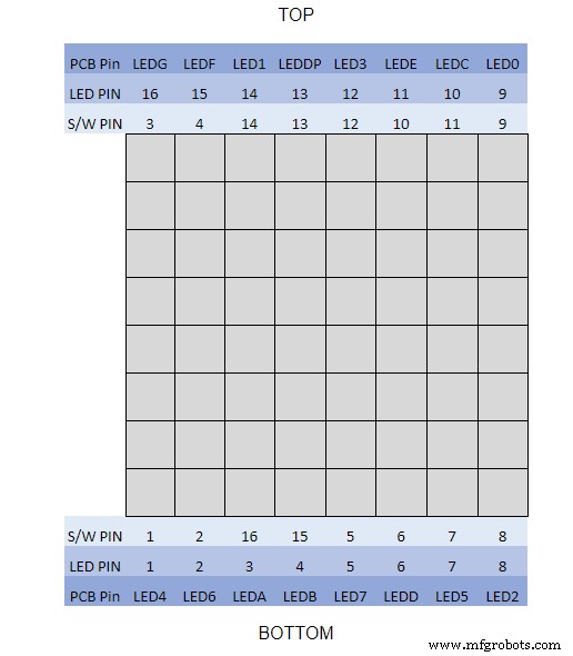
我用了万用表,把显示模块发出嗡嗡声。下表显示了软件引脚编号与显示板上 LED 引脚编号的不同之处。
要测试您的文字布局,请在普通白纸上打印出 62 毫米 x 62 毫米的微型文字显示版。
注意 LED 显示板的方向以匹配软件布局。
我将显示旋转保持为原始 Wouter Devinck 时钟,以防有人将 Wouter Devinck PCB 设计用于我的时钟。
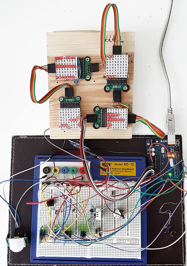
温度/湿度传感器下方的小按钮用于测试 30 秒同步。触摸按钮模块位于侧面安装的面包板的左下方。这个原型上的电线并不多,因为大部分电线都在显示矩阵中。在最后一个时钟上,此接线将手工完成到各个 LED。
在尝试构建最终时钟之前,我在该板上尝试了许多不同的字/时钟设计。
步骤 9:测试修改后的模块
我已经修改了字时钟草图,使MAX2719模块在接线模块后进行测试。
所有这些程序都从矩阵的左上角到右下角依次点亮每个 LED。
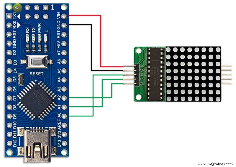
只需将 5 根线连接到 NANO 和 MAX2719 模块,然后从其 USB 端口为 NANO 供电。加载草图并让它运行。
只需依次插入每个模块即可检查接线。
从随附的 zip 文件下载测试草图。
MAX7219_LED_Test.zip
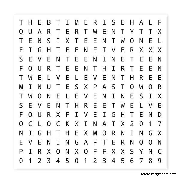
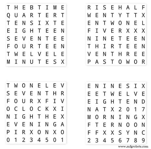
第 10 步:时间到字词映射
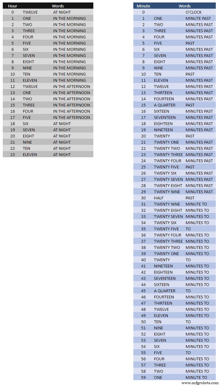
上表显示了词映射的时间。
对这些没有硬性规定,只需按照您所说的时间设置单词即可。
在我的时钟中,与 Wouter 时钟上的文字相比,我更改了以下内容。
“MINUTES”在过去 1 分钟和每小时 1 分钟时更改为“分钟”。在过去的“QUARTER”和小时的“QUARTER”之前添加了“A”。
中午把时间改成下午十二点钟了。
在午夜更改时间阅读晚上十二点。
午夜过后,时钟总是说在早上。
这些变化在时钟软件中很容易实现。
Word%2Bto%2BTime%2BTranslations.xlsx
第 11 步:电源
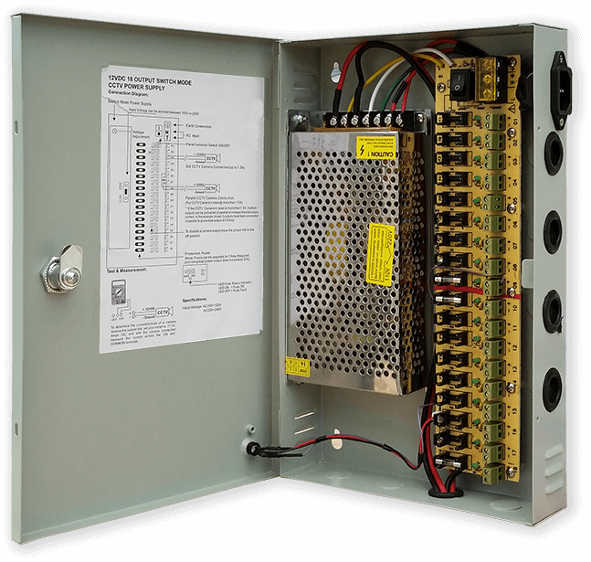
我使用一个普通的 12 伏电源装置来驱动我家中许多不同类型的电路。然后,这个 12 伏电源在每个电路上通过 5 伏模块局部降压,为控制板和各种模块供电。
我的常用电源有 18 个单独熔断的 12v 电路,每个电路都有一个 2A 保险丝。其中 9 个是备用电池。时钟板也有自己的板载保险丝。
如果您只运行这一个电路,那么任何稳压 5 伏电源都可以,只要它可以为您的电路提供电流。
我在 Vero 上设计了一个电源板,它使用 MP1584 微型电源。这会将我常用电源的 12v 输出转换为时钟的 5v。
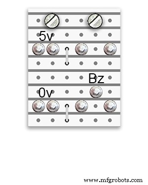
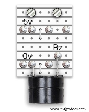
有两个额外的电源板由 Vero 板构成。
除了1个拿着蜂鸣器,他们只是为时钟的电源接线增加了额外的配电点。
电源要求
我测量了时钟的电流消耗,在低亮度下它使用 30mA 和全亮度 250mA。这当然会随着 LED 点亮的数量而变化。在阳光明媚的日子里,串行输出上指示的亮度级别为 10。这大约是 LED 最大功率的三分之二。如果 PIR 开启,整体功耗可以大大降低。如果时钟未检测到移动,这将使显示空白。
我会使用至少 500mA 的电源来为时钟供电。功率很大程度上取决于您采购的 LED 类型。
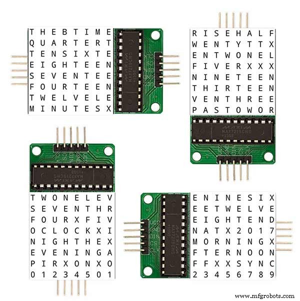
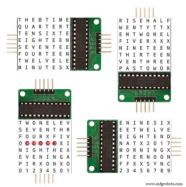
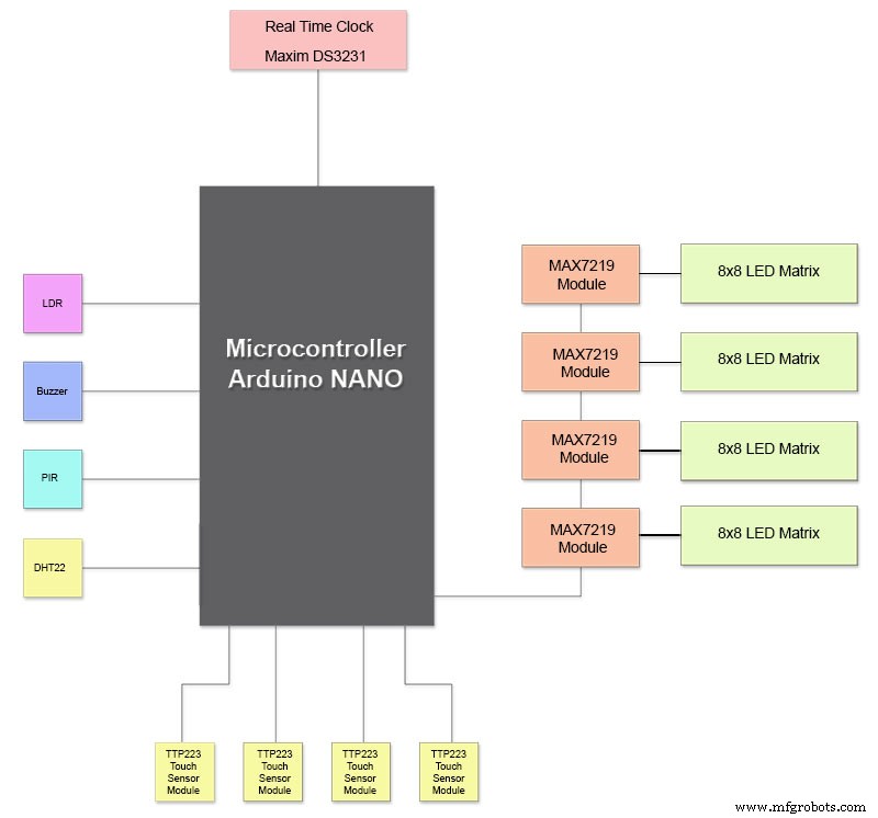
第 12 步:模块互连
上图显示了模块的连接方式。大多数模块直接连接到 Arduino Nano。
MAX7219 板仅通过模块 01 连接到 NANO。其他模块以菊花链形式连接在一起。
每个 8x8 LED 矩阵然后连接到 MAX7219 模块。
大部分接线是 MAX7219 模块和 LED 矩阵之间的连接。
使 NANO 与第一个 MAX7219 模块和 MAX7219 模块之间的距离尽可能短。还要确保为菊花链 MAX7219 的两端供电,因为大部分功率都由这部分电路消耗。
第 13 步:构建的构建顺序
假设首先完成所有原型设计和软件更改的构建顺序。
打印乙烯基转移。
切玻璃。
正面和背面切割 MDF 板。
在 LED 前板上切孔。
油漆中密度纤维板。
在玻璃上为传感器切孔。
将乙烯基转移贴在玻璃背面。
在 MDF 前板上切割传感器孔。
削减前板上的传感器模块回扣。
切割MDF背板并制作4个传感器接入孔。
在 MDF 板上添加三聚氰胺封边条,在前板添加白色,在后板添加黑色。
将后中密度纤维板拧到前中密度纤维板上。
制作Vero板、1个电源板和2个配电板。
修改 4 x MAX7219 板并添加 LED 接线。
暂时只在MAX7219端连接。
将所有模块和 Vero 板安装在 MDF 前板的背面。
在前中密度纤维板上构建所有 4 个 LED 矩阵并焊接 256 个 LED。
从电源 Vero 板和配电板连接所有 Batt 和 Earth 线路。
将所有电源连接到所有模块。
将所有接线连接到 Nano、MAX7219 模块、RTC、温度传感器、触摸传感器和蜂鸣器。
根据接线表将修改后的 MAX7219 板的所有接线机连接到 LED 矩阵。
从时钟远程连接 PIR 模块并连接 PIR 连接。
将 30 秒同步连接到您的主时钟(如果需要)。
使用芝加哥螺栓安装玻璃前显示面板,同时固定触摸传感器。
测试。
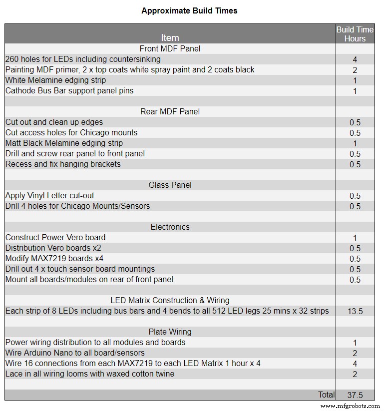
表 1 显示了此时钟的大致构建时间,并且会根据您的技能水平以及您必须使用的任何专业工具/工作空间而有所不同。
您可以轻松地将另外 40 小时的原型设计和编程时间添加到该列表中。
第 14 步:施工乙烯基贴纸
乙烯基贴纸
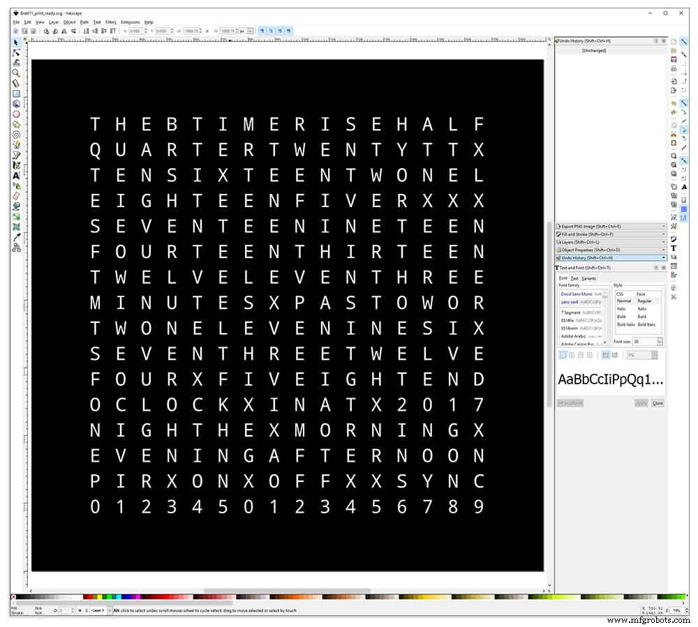
乙烯基贴纸是在 Inkscape 中设计的。
Inkscape 是专业品质的矢量图形软件,可在 Windows、Mac OS X 和 GNU/Linux 上运行。全世界的设计专业人士和爱好者都使用它来创建各种各样的图形,例如插图、图标、徽标、图表、地图和网络图形。
Inkscape 使用 W3C 开放标准 SVG(可缩放矢量图形)作为其原生格式,并且是免费的开源软件。
我从他的 GitHub 存储库下载了 Wouter Devinck 的原始 Inkscape 设计,然后在 Inkscape 中对其进行了修改以适合我的设计。在将最终设计发送打印之前,我在我的微型原型上尝试了许多不同的版本。
别忘了把贴纸反面打印出来!
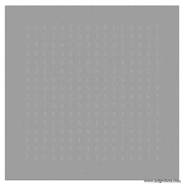
我使用了一家名为 Regal Signs &Graphics 的公司,该公司提供了我的黑色乙烯基贴纸,反向切割,去除了字母,并提供了一条应用胶带,全部售价约 27 英镑(含增值税)。
尽管它们对我来说很本地化,但我还是多付了一些钱,然后将贴纸放在一个漂亮的安全纸板管中。
我在为他们的机器以正确的格式获取设计时遇到了一些问题,但最后我从 Illustrator 以 eps 格式发送了它,Regal Signs 非常有帮助的人将其缩小到适合我的大小。我的 Inkscape 文件可以下载这里是乙烯基贴纸。
乙烯基贴纸来自 Regal Signs,字母已被淘汰,因此这为我节省了很多时间。贴纸的正面(玻璃)侧带有塑料胶带,背面带有应用纸。通常,您将胶带从侧面剥离,然后贴上贴纸,然后取下贴纸。我决定保留申请纸,因为它充当 LED 的漫射器。当我把申请纸留在上面时,我在申请前剪掉了贴纸周围多余的纸。
贴纸申请相对容易。在自己尝试之前,请确保您观看了一些关于 Vinyl 贴纸应用到玻璃的 YouTube 视频。
玻璃

时钟使用 4 毫米浮法玻璃,并被切割成 500 毫米 x500 毫米。由于边缘暴露在外,边缘也进行了抛光。这一切都是由我当地的玻璃工以 20 英镑完成的。
然后使用 5mm 玻璃钻在玻璃板上钻 5mm 孔。查看 YouTube 视频,了解如何在玻璃上钻孔。
我首先用丙酮清洁玻璃并确保它没有灰尘(非常重要)。然后我戴上一些塑料手套,以确保贴纸上没有任何指纹。
我用非常稀释的肥皂和水的混合物喷洒玻璃,然后非常缓慢地从贴纸上剥下塑料薄膜,露出前表面。
务必以锐角缓慢剥离薄膜,以便贴纸上的字母与转印纸保持连接。贴纸完全暴露后,将其贴在潮湿的玻璃表面上。
水/肥皂混合物可以让您将贴纸移动到玻璃上的正确位置。接下来使用信用卡并远离贴纸的中心去除任何气泡。让贴纸干燥过夜,然后从贴纸背面切掉玻璃上 4 个安装孔上的乙烯基。
Brett11_print_ready.svg
第 15 步:构建主板第 1 部分
主板
时钟的主板由 2 张 14 毫米 MDF 组成。背板在除顶部之外的所有侧面都比顶板小 10 毫米。顶部有白色边缘,而背面有黑色边缘。在墙上查看时,时钟看起来有 14 毫米深。

时钟的主板由 2 张 14 毫米 MDF 组成。背板在除顶部之外的所有侧面都比顶板小 10 毫米。顶部有白色边缘,而背面有黑色边缘。在墙上查看时,时钟看起来有 14 毫米深。
在原始的 Wouter Devinck 时钟和“加泰罗尼亚”Pijuana 版本上,使用了一块 18 毫米厚的 MDF,背面布线,为 PCB 和组件腾出空间。使用 2 张 MDF 意味着可以使用拼图简单地切割背板,而不是耗时且布满灰尘的布线。顶板为 503 毫米 x 503 毫米,以在玻璃周围提供 1.5 毫米的重叠。这将使玻璃免受撞击。

背板是用拼图切割出来的,留出14mm的元件空间。
包括元件在内的最深 PCB 是 10mm 深的 MAX 7219 模块。完成后,后板用胶水或螺丝固定在前板上。
前面板结构
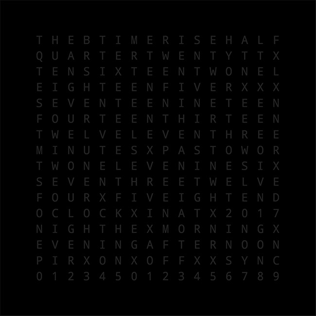
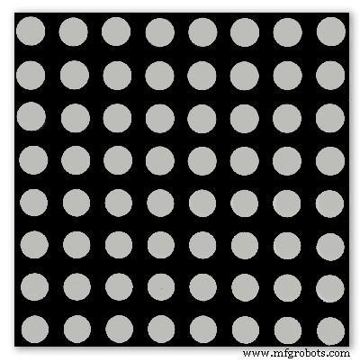
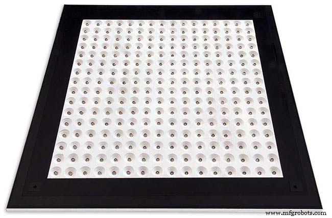
前面板装有 256 个 LED,这些 LED 通过 6.5 毫米孔和更宽的 18 毫米埋头孔发光,以照亮显示屏上的单个字母和数字。
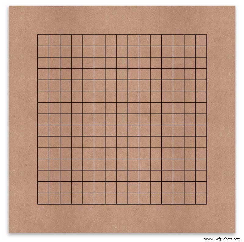
板上标有每个显示字符中心的钻孔位置。使用 500 毫米显示器,我测量了我的乙烯基片材,字符距边缘 62.5 毫米,相距 25 毫米。我在 MDF 上画了这些线,交叉点就是钻孔点。
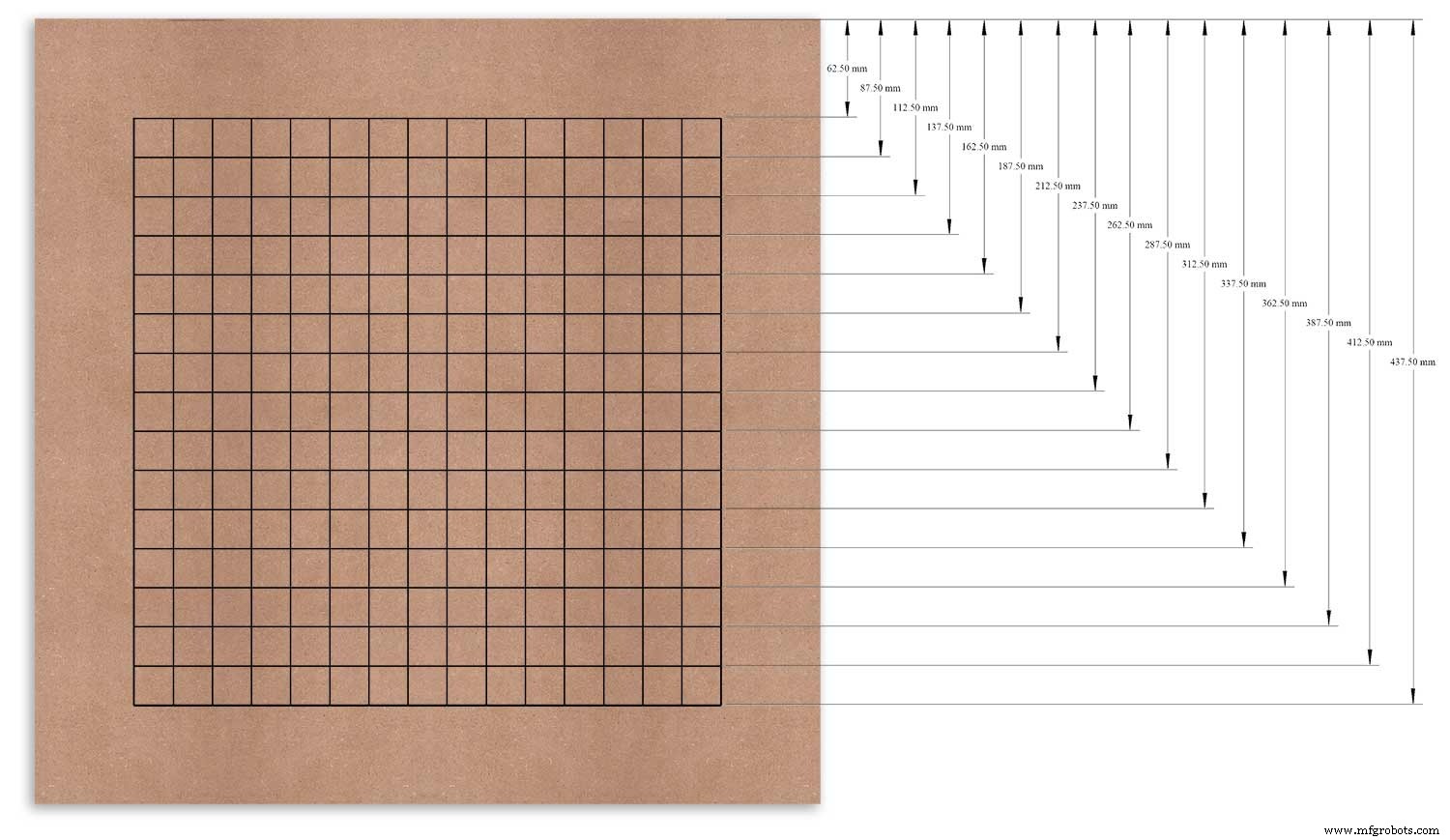
我以顶部边缘作为我测量的基准点,并从该点开始标记每一行。
以左边缘为基准对垂直列重复此操作。
网格的交点将成为6mm LED安装孔和18mm埋头孔的中心点。
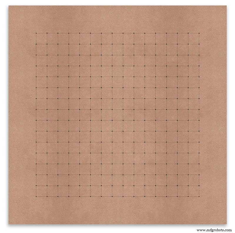
Using an automatic centre punch ( use a nail or screw if you don't have one) I punched the 256 intersection points of the grid.
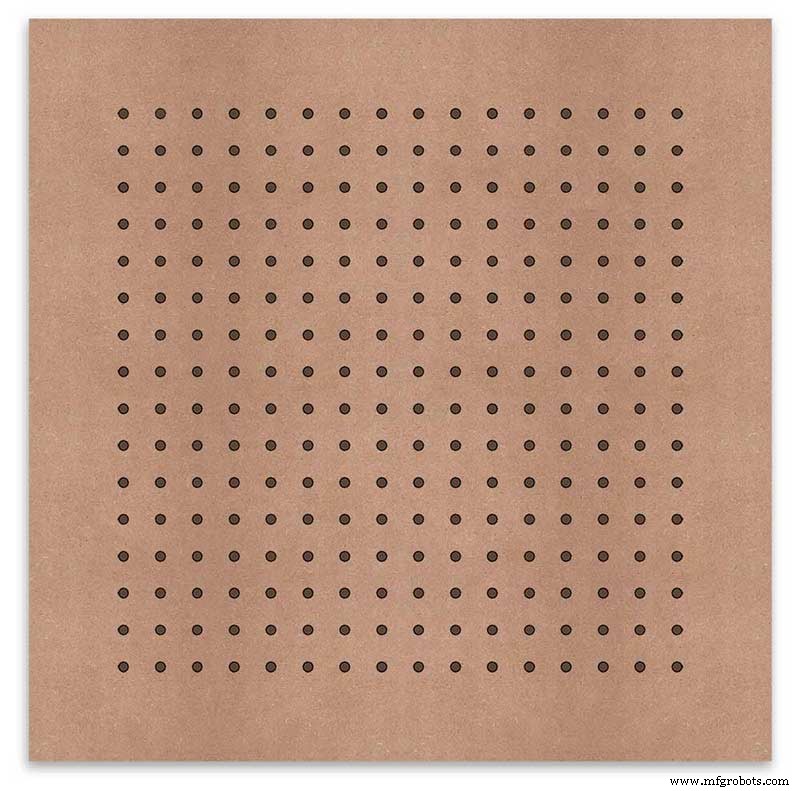
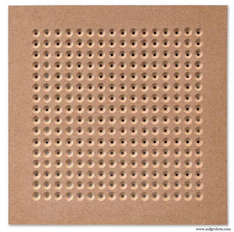
Using a drill bit to suite your LEDs (6mm in my case) and using the punched holes as a guide for the drill bit drill out all 256 LED mounting holes.
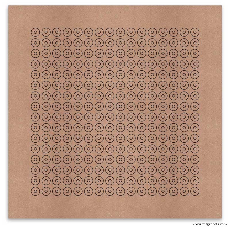
The next task is to drill the 256 18mm countersunk holes using a 20mm countersinking bit.
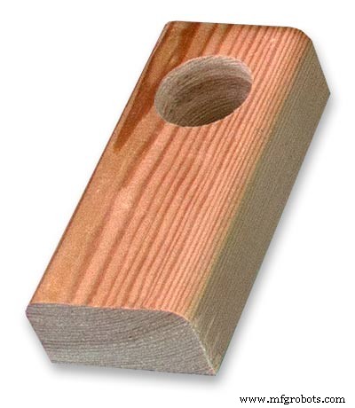
To keep the countersunk holes at a uniform depth and width I built a countersinking jig using an off cut of wood. To make the jig a hole is drilled in the wood off cut to just fit the silver rotating bezel of my drill chuck. Using a test piece of MDF the countersinking bit is then moved in and out of the chuck until a countersunk hole of the correct diameter is made when drilling through the hole upto the chuck in the off cut of wood. Once the correct distance is found the chuck is tightened and the main board is drilled 256 times by centring the hole in the wood over the existing 6mm holes then drilling down until the chuck bezel hits the hole in the countersinking jig.
Completed front board with 256 countersunk holes and 6mm holes for the LEDs.
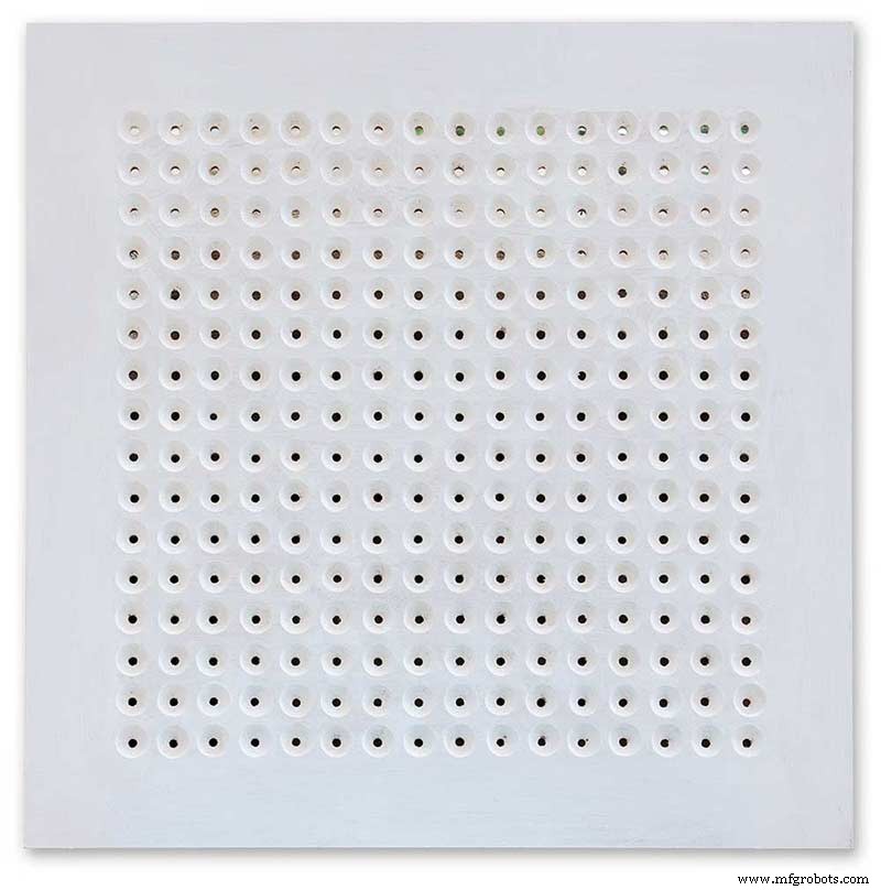
The board is then rubbed down and primed using MDF primer and painted white so the countersunk holes reflect the light from the LEDs.
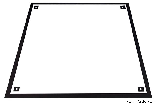
A black edge is painted around the outside edge to hide the board as the glass is 1mm shorter all round. This setback also helps the glass disappear from view on the final clock.
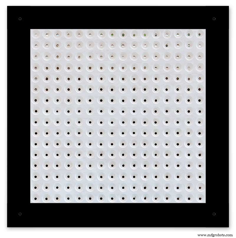
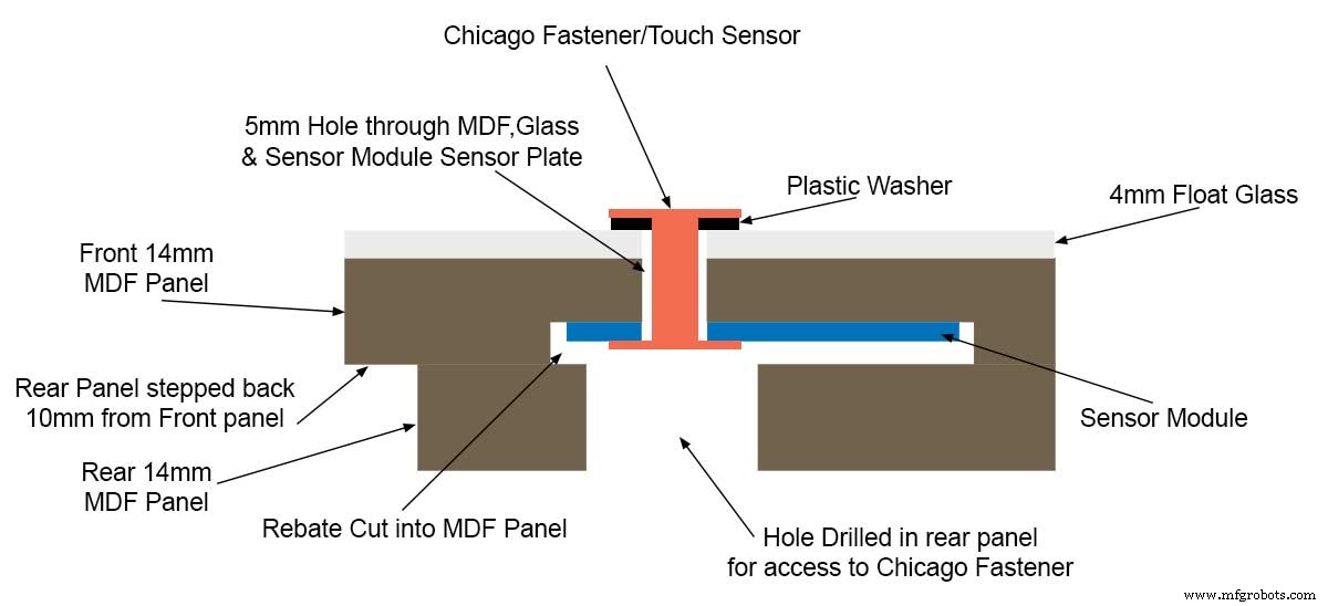
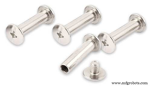
Four 5mm holes are then drilled in the corners to take the Chicago Fasteners. The Chicago Fasteners hold the glass in place, hold the touch sensors and provide a touch sensitive pad on top of the glass. The fasteners have 3mm shafts and will have a small bit of rubber tape wrapped around the shafts to protect the glass.
Turn the board over and drill a rebate with a forstner bit to take the four touch sensors. This hole will be offset from the hole drilled in the previous step.
Wall Mounts
The clock is fixed to the wall by two metal picture hanging mounts.
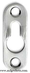
These are recessed into the frame so the highest point of the bracket is level with the frame.
Two 2" countersunk No6 screws sit in these bracket and hold the clock to the wall with a bit of tension so the dust seal is compressed.
Step 16:Construction Touch Sensor Mounting
The touch sensor modules are fixed to the front panel using the Chicago Fastener bolts. The Chicago Fastener bolts then act as touch sensors.
A 5mm hole is drilled through the sensor pad on the module to allow the Chicago Fastener bolt to pass through.
The sensor pad is insulated by the MDF panel and a plastic washer.
The touch pad on the sensor module has a 5mm mounting hole drill through the sensor.

Touch sensors in rebates behind rear panel. Holes drilled into rear panel allows access to the Chicago Fasteners that hold the sensors/glass front in place.
Clock front panel with four Chicago Fastener tops acting as touch plates.
Step 17:Electronic Components &Modules
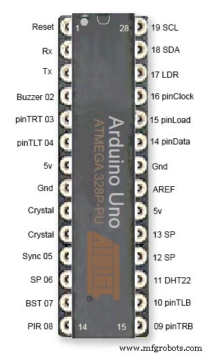
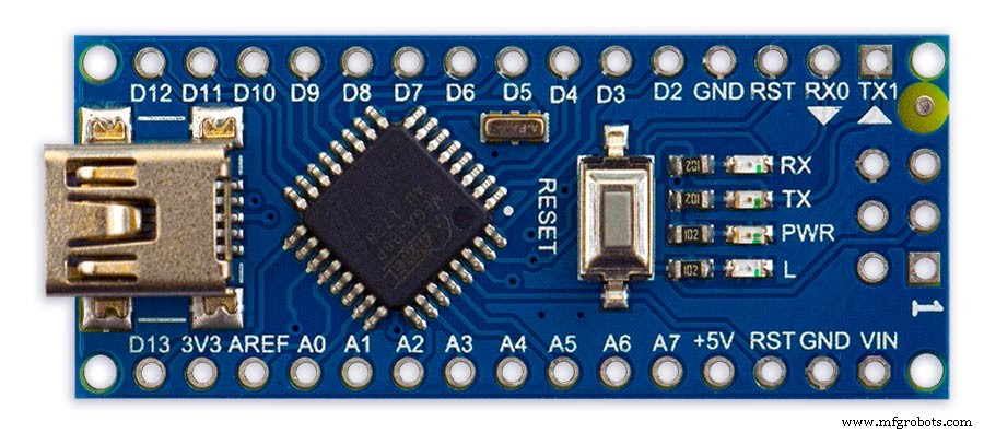
ATmega328 pin connections in case you want to prototype the circuit on an Arduino Uno. Note BST pin 07 is not used.
Pin label numbers refer to Arduino IDE numbers.
LEDs
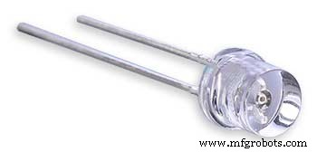
Make sure you purchase your LEDs from a good source. These LEDs will be on for many hours a day. I have has problems with LEDs failing after a few weeks use.
My LEDs Specs
5mm White Flat Top LEDs offering a pure and consistent colour with a wide angle ultra bright light output.
Colour :White
Quantity :256
Lenses Type :Round Flat Top
Crystal ClearBrightness :13000mcdForward
Voltage :3.2v - 3.8v
Forward Current :20mA (typical), 30mA (Max)
Viewing Angle :120 degrees
DHT22 Temperature &Humidity Sensor
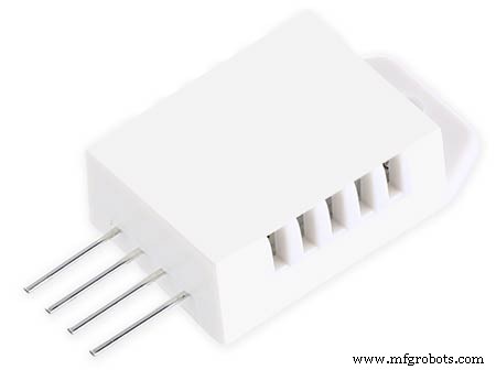
The DHT22 is a basic, low-cost digital temperature and humidity sensor. It uses a capacitive humidity sensor and a thermistor to measure the surrounding air, and sends out a digital signal on the data pin.
You can only get new data from it once every 2 seconds, so sensor readings can be up to 2 seconds old.
Simply connect the first pin on the left to 3-5V power, the second pin to your data input pin and the right most pin to ground.
To prevent the temperature of the inside clock case being measured the top and left side vent of the DH22 are covered over with tape. This also stops dust being drawn into the clock case.
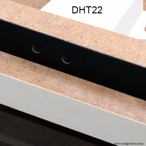
The DHT22 is mounted with its right open side mounted tight against the lower rear cover.Two small holes are drilled in the lower edge of the rear MDF board to allow air from the room to circulate around the sensor.
Arduino NANO
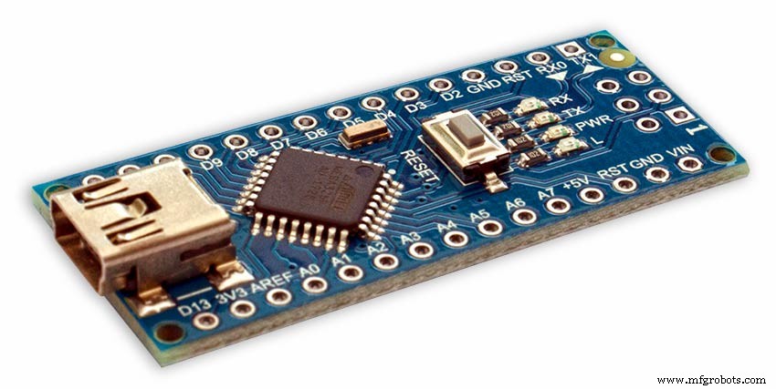
PowerThe Arduino Nano can be powered via the Mini-B USB connection, 6-20V unregulated external power supply (pin 30), or 5V regulated external power supply (pin 27). The power source is automatically selected to the highest voltage source.
Memory
The ATmega328 has 32 KB, (also with 2 KB used for the bootloader.
The ATmega328 has 2 KB of SRAM and 1 KB of EEPROM.
Input and Output
Each of the 14 digital pins on the Nano can be used as an input or output, using pinMode(), digitalWrite(), and digitalRead() functions. They operate at 5 volts. Each pin can provide or receive a maximum of 40 mA and has an internal pull-up resistor (disconnected by default) of 20-50 kOhms. In addition, some pins have specialized functions:Serial:0 (RX) and 1 (TX). Used to receive (RX) and transmit (TX) TTL serial data. These pins are connected to the corresponding pins of the FTDI USB-to-TTL Serial chip.
External Interrupts:2 and 3.
These pins can be configured to trigger an interrupt on a low value, a rising or falling edge, or a change in value. See the attachInterrupt() function for details.
PWM:3, 5, 6, 9, 10, and 11. Provide 8-bit PWM output with the analogWrite() function.
SPI:10 (SS), 11 (MOSI), 12 (MISO), 13 (SCK). These pins support SPI communication, which, although provided by the underlying hardware, is not currently included in the Arduino language.
LED:13. There is a built-in LED connected to digital pin 13. When the pin is HIGH value, the LED is on, when the pin is LOW, it's off.
The Nano has 8 analog inputs, each of which provide 10 bits of resolution (i.e. 1024 different values). By default they measure from ground to 5 volts, though is it possible to change the upper end of their range using the analogReference() function. Analog pins 6 and 7 cannot be used as digital pins. Additionally, some pins have specialized functionality:I2C:4 (SDA) and 5 (SCL). Support I2C (TWI) communication using the Wire library (documentation on the Wiring website).
There are a couple of other pins on the board:AREF. Reference voltage for the analog inputs. Used with analogReference().重启。 Bring this line LOW to reset the microcontroller. Typically used to add a reset button to shields which block the one on the board.
Communication The Arduino Nano has a number of facilities for communicating with a computer, another Arduino, or other microcontrollers. The ATmega328 provide UART TTL (5V) serial communication, which is available on digital pins 0 (RX) and 1 (TX). An FTDI FT232RL on the board channels this serial communication over USB and the FTDI drivers (included with the Arduino software) provide a virtual com port to software on the computer. The Arduino software includes a serial monitor which allows simple textual data to be sent to and from the Arduino board. The RX and TX LEDs on the board will flash when data is being transmitted via the FTDI chip and USB connection to the computer (but not for serial communication on pins 0 and 1). A SoftwareSerial library allows for serial communication on any of the Nano's digital pins. The ATmega328 also support I2C (TWI) and SPI communication. The Arduino software includes a Wire library to simplify use of the I2C bus. To use the SPI communication, please see ATmega328 datasheet.
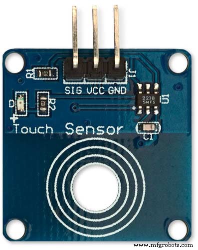
TTP223 Touch Sensor Module
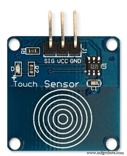
The touch Sensor Module is bolted to the front panel using the glass mounting bolts. The bolt goes through a 5mm hole drilled in the middle of the sensor.Note the mounting bolt is touched to trigger the sensor but is insulated from the sensor itself through plastic washers. Four of these modules are used in the clock one mounted on each corner of the glass.
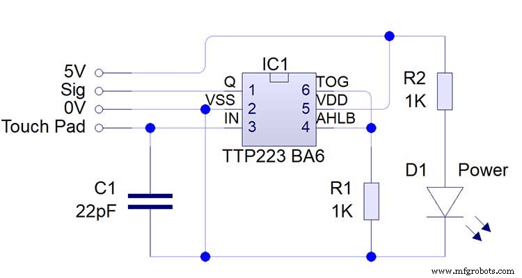
Note the LEDs are not required and are removed from the modules (just break them off) to save power.
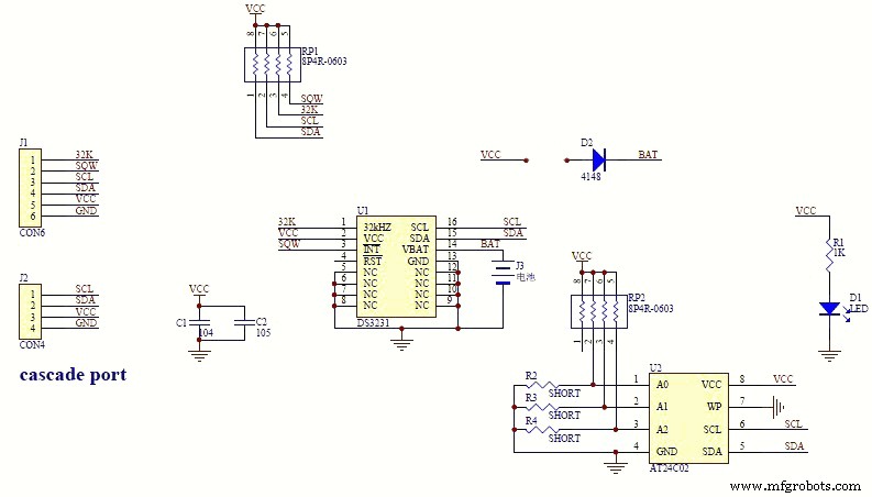
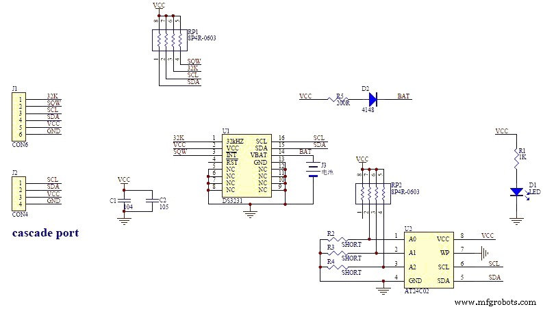
DS3231 AT24C32 I2C Precision Real Time Clock Module
My clock uses a DS3231 AT24C32 I2C Precision Real Time Clock Module.The module comes supplied with a Lithium-Ion rechargeable battery see diagram below. I use a non rechargeable battery so have removed resistor R5 from the module.
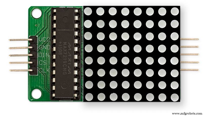
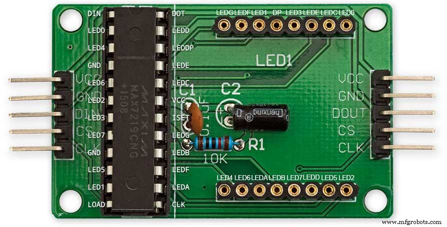
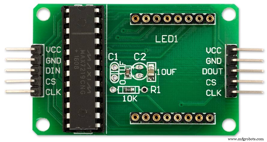
MAX7219 Display Module
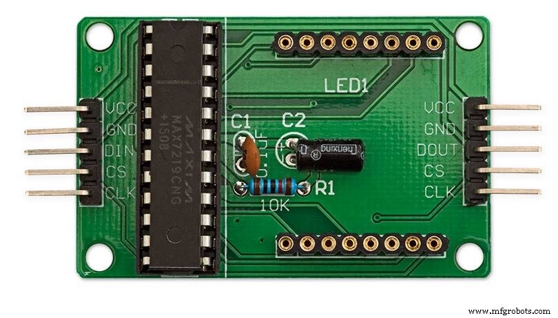
MAX7219 LED current limiting
The max current through the LEDs is set by a single resistor R1 on the module. The value of resistor can be found from the table below.
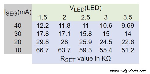
The module comes with a 10K resistor preinstalled but this can be removed and a resister to match your LEDs current added in its place. My LEDs Forward Voltage is 3.2v - 3.8v @ 20mA. They can handle 30mA max but for long LED life 20mA is best. I have used 22KΩ resistors which will limit the current to around 20mA when the light levels are at their peek.
See setting automatic brightness levels.
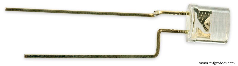
1088AS LED Dot Matrix display

1088AS LED Dot Matrix display view of lower edge Pins 1 to 8 left to right.
This is used for prototyping and is not required in the final project.
LDR
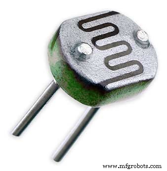
An LDR is used to sense the ambient light levels. The LDR is around 500Ω in bright light and 10MΩ in the dark.
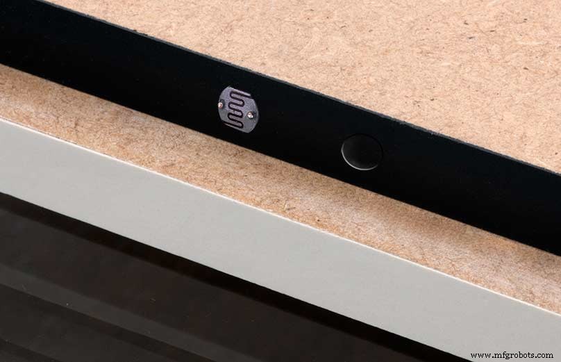
The LDR is positioned underneath the clock on the rear MDF panel.
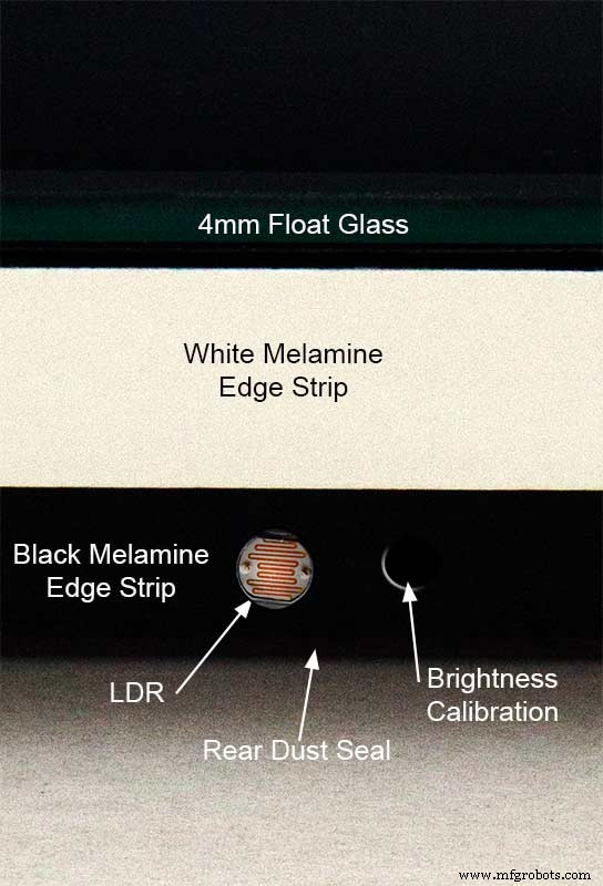
Next to the LDR is a hole to give access to the trimmer resister to calibrate the LED brightness control.
Component List
Step 18 Dust Seals
To prevent ingress of dust two dust seals are fitted.
On the rear MDF board a 2mm soft foam rubber dust seal is fitted. When the clock is hung on its hanging hooks the seal is under pressureand seals the back of the clock to the wall.
The seal is self adhesive and is fitted with a 5mm gap to the edge of the rear MDF board.
On top of the front board to prevent dust getting under the glass a strip of self amalgamating rubber is fitted 5mm from the board edge.
To prevent the glass from cracking when the Chicago bolts are tightened 4 small square of rubber are also fitted around the holes in the glass.
I punched holes for the Chicago Bolts in the rubber with a leather punch.
Step 19:Schematic
Nano Connections
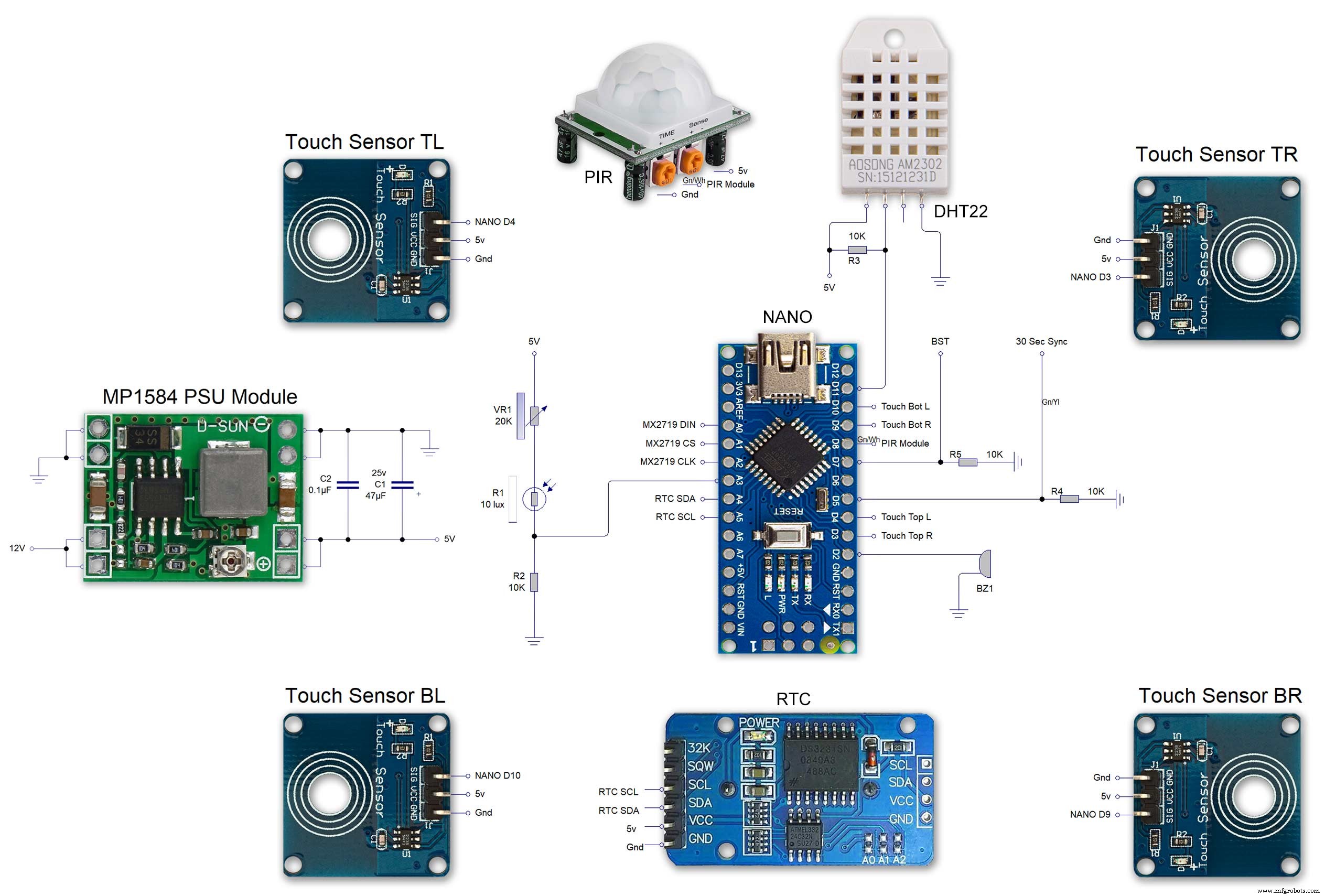
The connections to the Arduino Nano. Download the full size file from the hardware section
MAX2719 connections


The 4 MAX7219 modules and the connected LED matrixes.
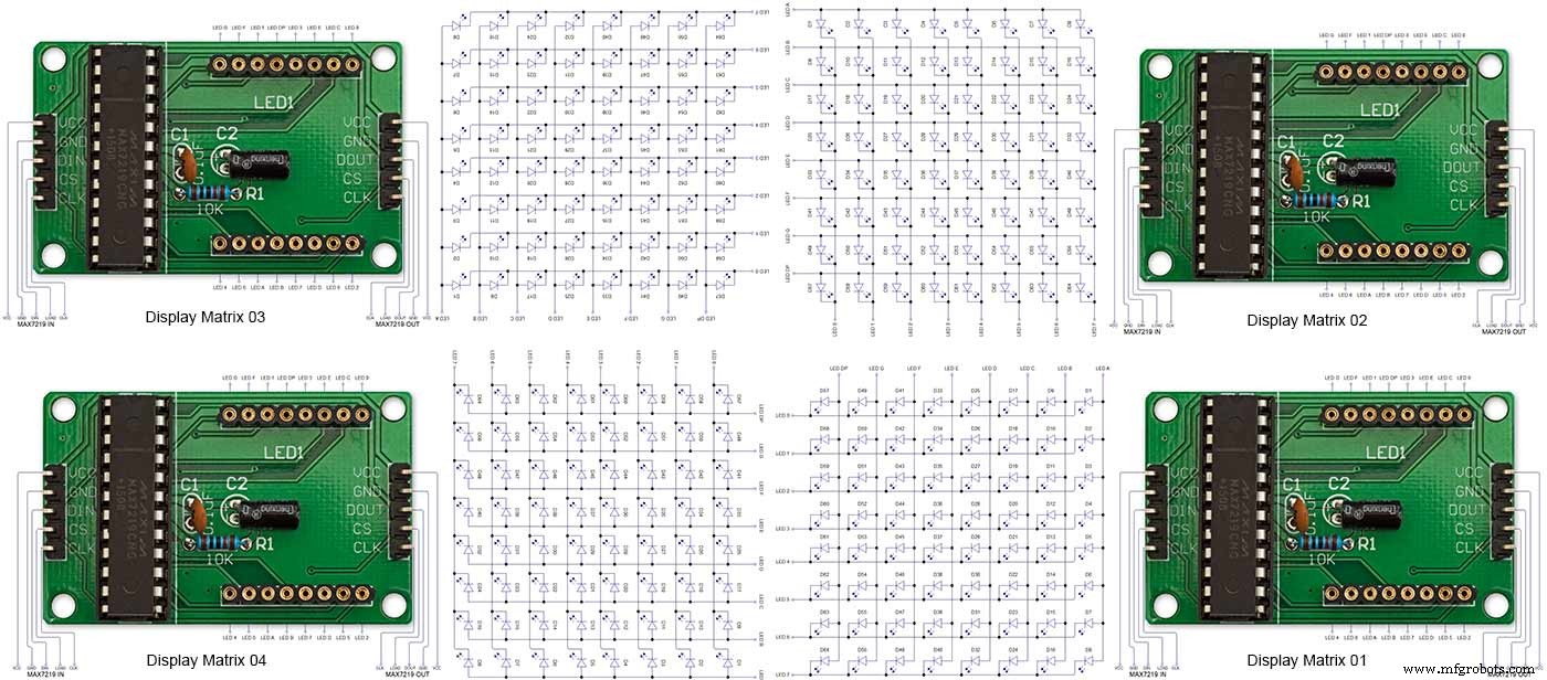
Note the LED display matrixes are rotated anti-clockwise 90 degrees from each other starting from display matrix 01.Display Matrix 01 input is wired to the Arduino CLK, DIN and LOAD the output is taken to the input of Display matrix 02 etc etc.
Step 20:Wiring Building the LED Matrixes
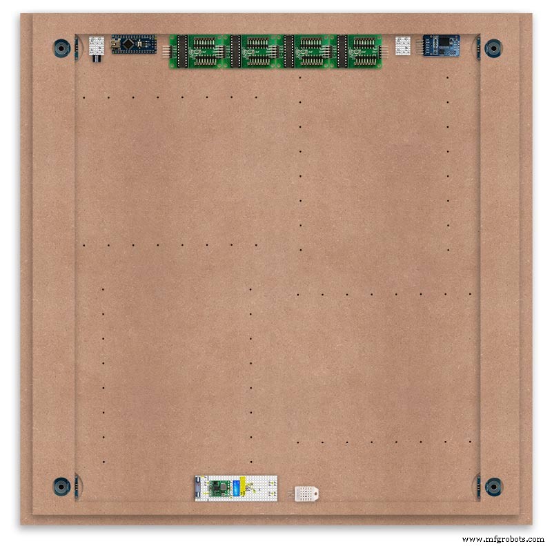
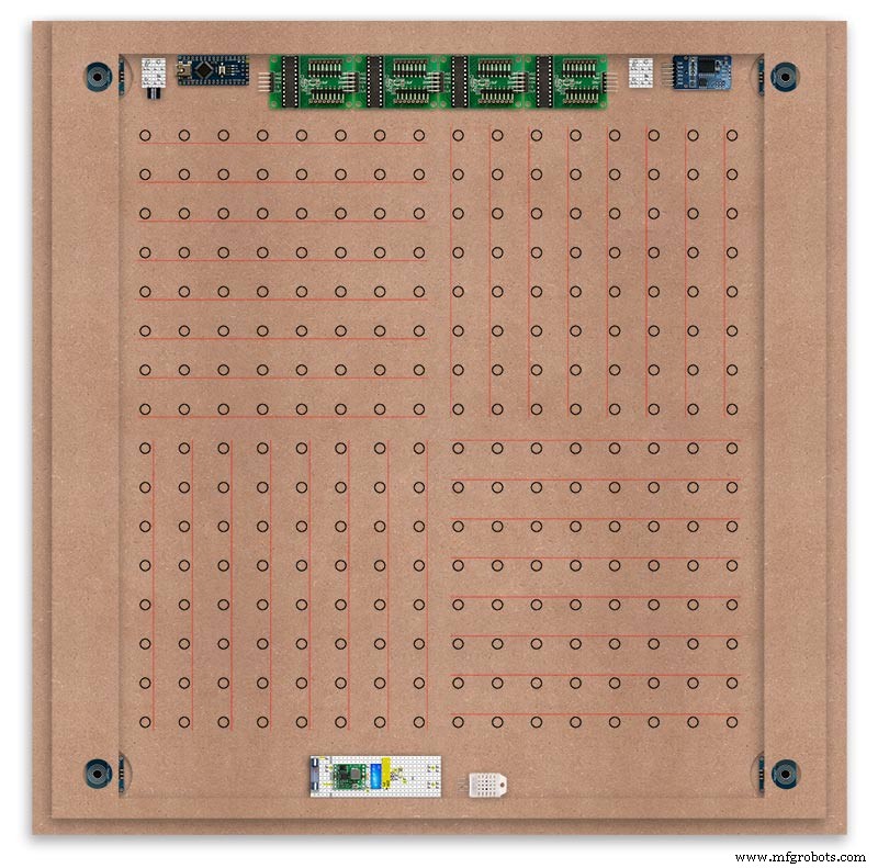
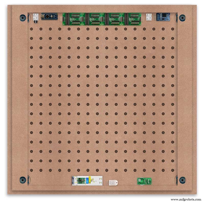
Module Locations

The module locations are shown above. The four sensors are located in the recesses on the main board behind the rear board. Holes are cut into the rear board to allow access for fit the Chicago Bolts/Sensor pads.
The four MAX7219 Display Modules are soldered together and are mounted in the centre top of the board. This keeps the data links between the boards as short as possible.
The Arduino Nano is mounted on the left of the MAX7219 Display Modules and the RTC on the right. The RTC battery holder on the base of the RTC module is recessed into the main board.
The Vero board containing the power module is located on the lower part of the board. There are two power distribution boards mounted on the top of the clock. The main 5v 2A feed cable is taken to both of these boards and power is then distributed to the other boards from these points.
The MAX7219 board power is fed from the left board and daisy chained through each board then taken out the forth board to ensure they are fed with 0v and 5v from both ends.
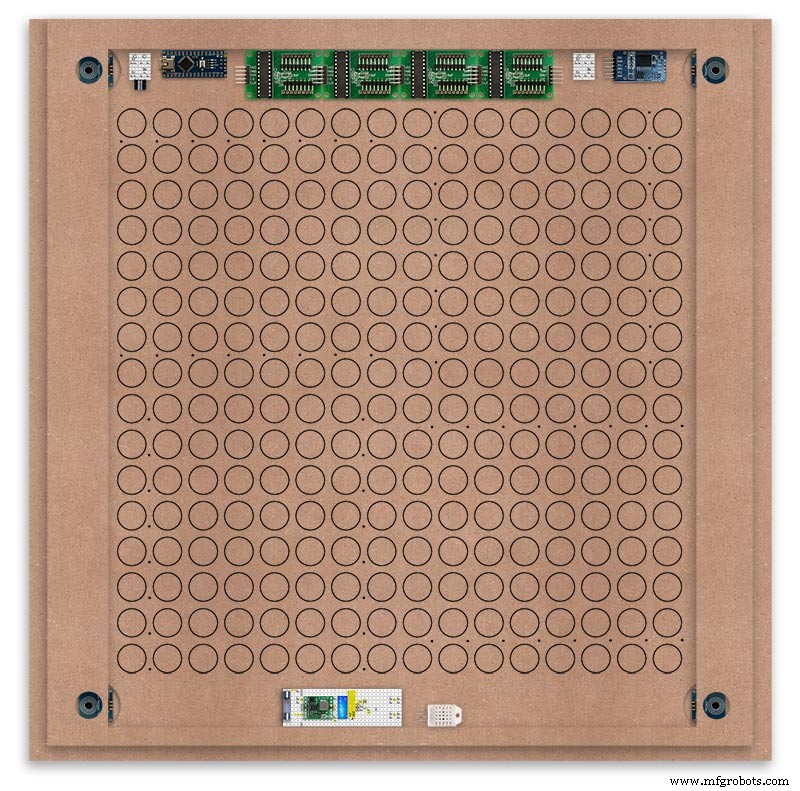
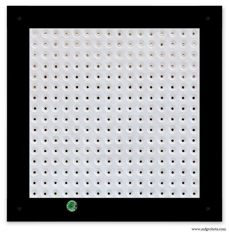
The LED locations are shown. The LED matrixes each contain 64 LEDs and are labelled 1 to 4.
These correspond to the 4 MAX 7219 modules mounted above numbered 1 to 4 left to right. Note this is the rear of the clock so number will be revearsed.
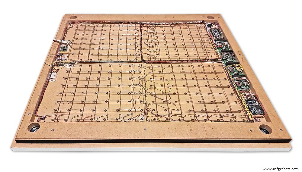
The LED Matrixes are built up off 2 types of BUS Bars per module. A Cathode Bus at 10mm high and an Anode BUS bar at 2mm high.
There are 8 Cathode and 8 Anode BUS Bars per module. Each module has 16 x 15mm panel pins hammered into the board in the position shown to support the 10mm high Cathode BUS.
The 15mm panel pins are hammered in 5mm (I used a 10mm piece of metal bar as a gauge) leaving 10mm as Cathode BUS bar support pins.
As shown above the pins correspond with the thick parts of the board not the recess for the LEDs on the front of the board. Note the LED recess is on the front of the board and can't be seen from the back.

0.9mm copper wire is then soldered to each pair of pins to form the Cathode BUS Bar.
Note the rotation of each module and also the modules are in reverse as it is the back of the board the LEDs are connected to.
The Anode BUS Bars are shown below in Red and are supported off each LED Anode about 2mm off the MDF board. No Pins required.

Both Cathode &Anode BUS Bar locations are shown below.
Each LED is connected to an Anode and Cathode of the Matrix.
Step 21:Wiring the LEDs
LEDs
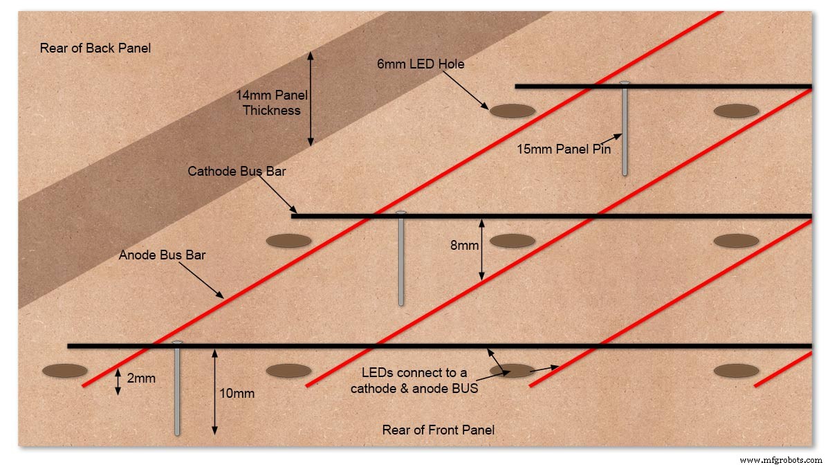
Diagram showing Bus Bar layout with panel pins supporting the Cathode Bus. This module has horizontal Cathode and vertical Anode Bus Bars.
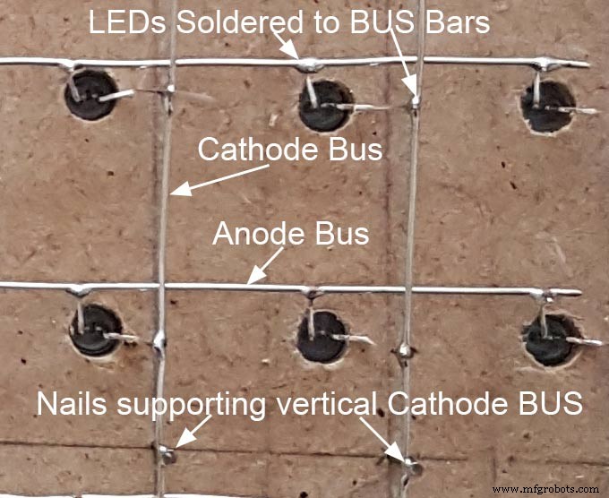
Close up section of Module wiring.The Cathode BUS Bars run vertically and the Anode BUS Bars run horizontally on this module. The Anode &Cathode BUS Bars have an 8mm vertical separation.
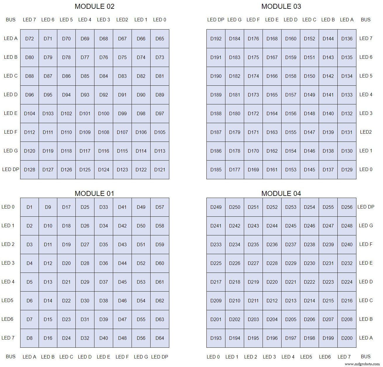
The LEDs are connected to the matrixes and MAX7219 modules from the rear. The LED positions will be reversed and of course rotated 90° relative to the next module. This makes it very complicated connecting the correct LEDs and Bus bars from the rear of the board. The table below shows the LED positions in the blue boxes with the BUS Bar matrix position in black around the outside as they appear from the back of the front MDF board.
The LEDs are bent in a jig to keep the position in the display constant and to speed up construction. Each LED has four bends two on each leg that's 1024 in total! The Cathode leg is bent 90° from the Anode.
The Matrix grids are wired to the corresponding pins on the MAX7219 modules according to the layout table.
There are 16 wires to each module.
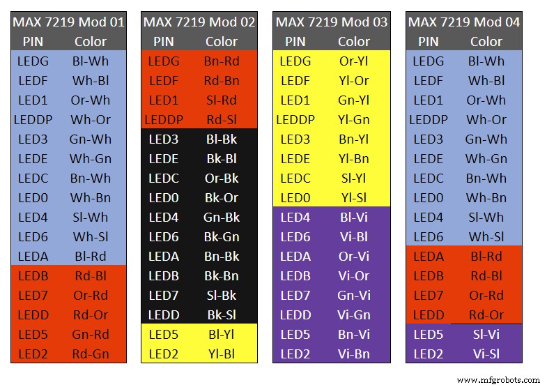
Table 1 Module LED Matrix Wiring Colour Code is shown above.
Each Module has 16 wires connecting it to the LED Matrixes. I have used 50pr 0.5mm cable so the last 14pr colours are duplicated. On Mod 4 I went out of order and missed out the Sl/Vi at the start so have put it in at the end.
Step 22:Wiring Modifying the MAX7219 Modules
Before wires can be connected to the MAX 2917 modules they will need to be modified.
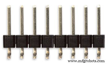
Two sets of 8 90° pin connectors will to be soldered to the lower edge of the existing LED matrix connector.

Modified MAX7219 module with 90° pin connectors soldered in place to the bottom of the old LED Matrix connectors.
Wires are taken away from these points to the LED matrix on the main MDF board as per the LED Matrix Wiring Colour Code table on the previous step.
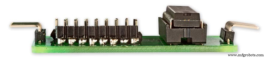
Side view showing the pins soldered to the side of the old LED Matrix connector pins just above the PCB.
Note if your MAX7219 Module does not have surface mount components the 90° pin connectors may need to be trimmed back so they don't foul R1, C1 or C2.
MAX7219 LED current limitingThe max current through the LEDs is set by a single resistor R1 on the module. The value of resistor can be found from the table below.

The module comes with a 10K resistor preinstalled but this can be removed and a resistor to match your LEDs current added in its place.
My LEDs Forward Voltage is 3.2v - 3.8v @ 20mA. They can handle 30mA max but for long LED life 20mA is best. I have used 22KΩ resistors which will limit the current to around 20mA when the light levels are at their peek.
Note this sets the max current through your LEDs actual brightness is controlled by the LDR/software/ trimmer resistor and will usually be far less than this.
Setting Automatic Brightness Levels
The clock automatically senses the ambient light and adjusts the LEDs accordingly.
When first installed the clock will need to be calibrated to the maximum light levels in its actual location.

Connect a mobile, laptop/tablet etc via a suitable cable to the mini USB port of the clock and open an app to monitor the serial port.
I use Slick USB 2 Serial Terminal on my S7 via an OTG cable and USB to mini USB cable.
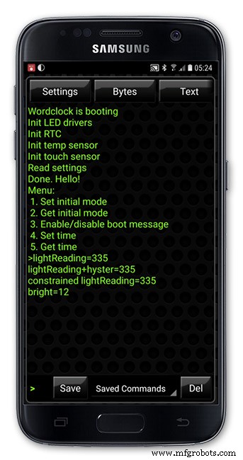
The clock will reboot and after the initial start screen you will see the following data updating down the screen.
You don't need to worry about lightReading or constrained lightReading+hyster just light reading, and bright.
With the clock in position and the ambient light at its maximum levels carefully insert a flat bladed jewellers screwdriver into the access hole just to the right of the light sensor.
Turn the screwdriver slowly until the light reading =600 (or your level set in brightness.cpp) and bright =15.
Your clock will now go to max brightness when the ambient light is at its maximum.
If you turn the screwdriver too far the light reading will go over 600 but the bright reading will not increase.
If you want the clock to be dimmer right across the range of ambient light levels adjust the light reading to a level less than 600 at max ambient light levels.
Note when bright=15 this will output the max current to the LEDs. The max current is set by R1( RSET) on the MAX7219 module and this should be chosen for your type of LED used in the display.
Step 23:Wring Mini USB Port
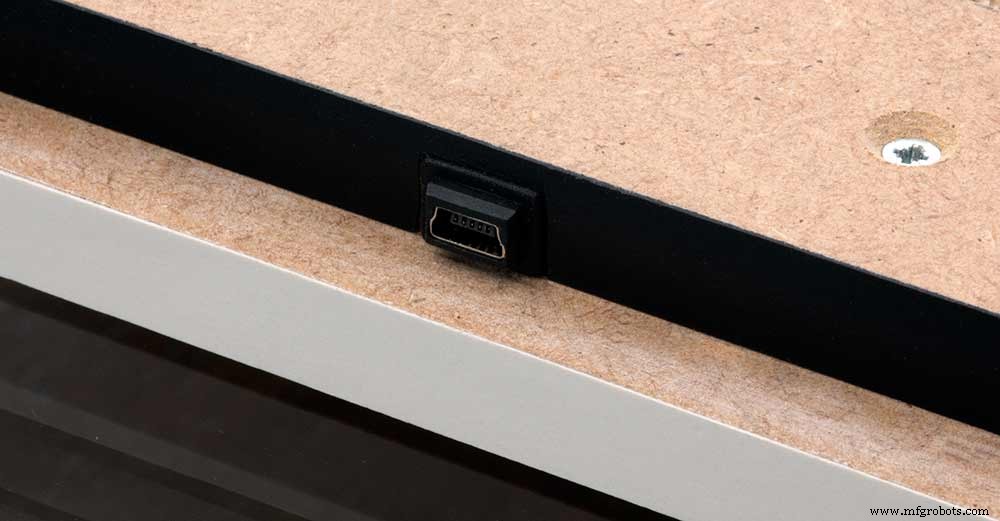
To allow adjustment/checking of light levels and programming of the clock a Mini USB socket is cut into the right hand side of the rear MDF sheet.
I have used a 25cm 90° Right angle Mini USB Male to Female Extension Cable and stripped back the insulation sleeve and shielding to expose the wires. This allows the cable to bend around the sharp angles and tight spaces of the enclosure.
Step 24:PIR Controlled Display Shutdown
This is optional as a Doppler Radar module can be fitted inside the clock instead.
See next section.
The PIR when enabled on the word clock menu (bott left PIR On, bott right PIR Off) turns on the display when movement is detected in the room.
When no movement is detected the display turns off after a set period of time. When the PIR is enabled the displays shows "PIR ON" and when disabled (display always on) it shows "PIR OFF" Note when the PIR is not enabled the display is always On.
The PIR module is fitted remote from the clock in a modified chrome light switch box. The box is cut into a plasterboard wall and also contains a switch to turn the clock off. The module itself is very small and can be mounted in a tiny enclosure if you don't want it on show. It will not work behind glass so if you wanted to mount it on the clock a hole would need to cut in the glass. This is very easy to do with a large hole cutter.
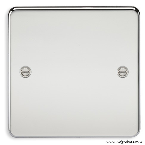
A blank chrome switch plate and back box are used to house the power switch and PIR module.
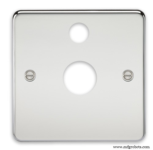
Two holes are drilled in the blank switch plate for the power switch and PIR lens.
The hole are centre punched, pilot drilled and then drilled out just big enough for a step cutter to fit through. The hole for the PIR diffuser is cut just big enough for the lens to go through with a friction fit.
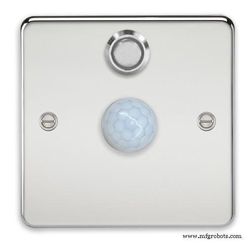
The completed switch plate.
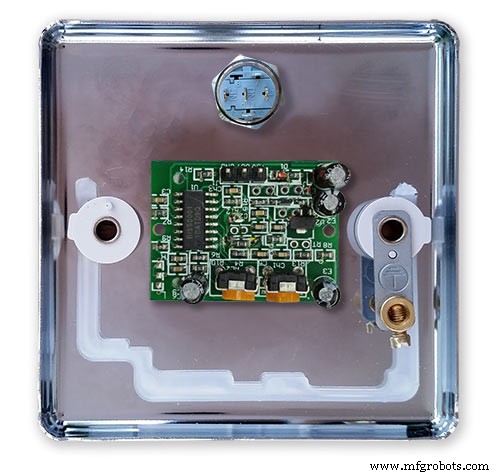
The 12 volt supply +ve is terminated on the switch with the 0v terminated on the earth screw.
12 volts is then fed back upto the clock PSU Vero board from the other side of the switch and again the earth screw. 5 volts are fed from the clock PSU Vero board to supply the PIR module.
The 5 volts and PIR sensor wire to the clock terminate on PCB header sockets. These are is plugged into the PIR Module header pins. The sync cable is terminated on a header pins and connects to the Master Clock 30 second sync cable via a single header socket.
The PIR has 2 trimmer resistors for adjusting sensitivity and also length of time the PIR &display stay activated.
PIR On/Off Control:The PIR is turned on and off in word clock mode by touching the bottom left sensor to turn the PIR on or by touching the right sensor to turn the PIR off. Note when the PIR is set to off the display stays on permanently. When you change the PIR setting the work "PIR ON" or "PIR OFF" is displayed for 5 seconds.
When initial power up the default is PIR off if you switch the PIR On straight away the display will go off as the PIR takes a minute or so to initialise before detecting movement.
Photo 6 &7 "PIR ON" or "PIR OFF" are displayed for 5 seconds when PIR setting is changed.
Step 25:Doppler Radar Control Option
Optional Doppler Radar Module can be added in place of the PIR above.
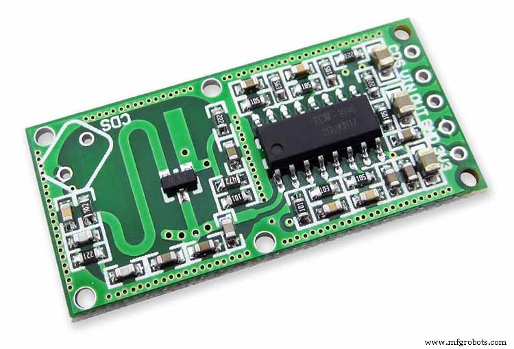
The Doppler Radar when enabled on the Word Clock menu (bott left PIR On, bott right PIR Off) turns on the display when movement is detected in the room. A check is made for motion on every quarter hour. When no movement is detected the display turns off until movement is detected again.
When the PIR is enabled the displays shows "PIR ON" and when disabled (display always on) it shows "PIR OFF" Note when the PIR is not enabled the display is always On. Unlike PIR modules the Doppler Radar module can see through glass and plastic and is fixed into the case of the clock behind the glass and PVC sticker. The module has a range of around 5m or 16' 5".
Doppler Radar Module fixed inside the case. A hole is drilled in the front panel to allow the module to monitor the room.
Front panel showing hole through to the Doppler Radar module microwave sensor.
The module is hidden from view behind the PVC sticker and glass.
Step 26:PIR/Doppler Radar On Off Control
The PIR is turned on &off in word clock mode by touching the bottom left sensor to turn the PIR on or by touching the right sensor to turn the PIR off.
Note when the PIR is set to off the display stays on permanently.

When you change the PIR setting the work "PIR ON" or "PIR OFF" is displayed for 5 seconds.
When initial power up the default is PIR off if you switch the PIR On straight away the display will go off as the PIR takes a minute or so to initialise before detecting movement.
Step 27:Setting Automatic Brightness Levels
The clock automatically senses the ambient light and adjusts the LEDs accordingly.
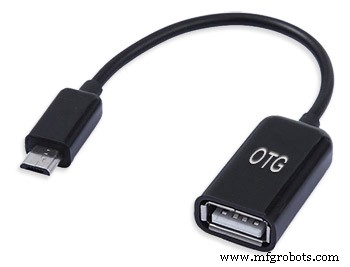
When first installed the clock will need to be calibrated to the maximum light levels in its actual location. Connect a mobile, laptop/tablet etc via a suitable cable to the mini USB port of the clock and open an app to monitor the serial port. I use Slick USB 2 Serial Terminal on my S7 via an OTG cable and USB to mini USB cable.

The clock will reboot and after the initial start screen you will see the following data updating down the screen.
You don't need to worry about lightReading or constrained lightReading+hyster just light reading, and bright.With the clock in position and the ambient light at its maximum levels carefully insert a flat bladed jewellers screwdriver into the access hole just to the right of the light sensor. Turn the screwdriver slowly until the light reading =600 (or your level set in brightness.cpp) and bright =15. Your clock will now go to max brightness when the ambient light is at its maximum. If you turn the screwdriver too far the light reading will go over 600 but the bright reading will not increase.
If you want the clock to be dimmer right across the range of ambient light levels adjust the light reading to a level less than 600 at max ambient light levels.
Note when bright=15 this will output the max current to the LEDs. The max current is set by R1( RSET) on the MAX7219 module and this should be chosen for your type of LED used in the display.
Step 28:Setting the Clock
The clock is set in the digital clock mode by touching the bottom left sensor.
The hour digits will now flash twice a second to indicate the clock is in time setting mode.In this mode the sensors have the following functions.
Top right - steps the hours or mins digits up
Top left- steps the hours or mins digits down
Bottom left 1sr press - enters the time setting mode selecting hours digits
Bottom left 2nd press -selects the mins digits for changing
Bottom left 3rd press -exits time setting mode and sets the time
Bottom right - resets the seconds to 00
Step 29:Synchronisation
If you have connected a 30 second master clock sync cable then the clock will jump back or forward to 30 seconds when out of time setting mode. If you don't have a Master Clock to sync to then the clock will fall back on the on board temperature compensated real time clock which in itself is a very precise quartz clock.
Just reset the seconds roughly in sync to the seconds (within 10 seconds either way) and wait for the clock to sync once out of time setting mode.
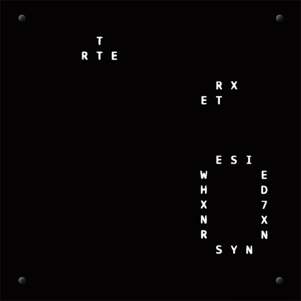
The animated loop below shows the Word Clock is running fast by several seconds. A synchronisation pulse is received from the Master Clock every 30 seconds on the minute and half minute synchronising the clock on 30 seconds.
The clock will ignore the 30 second synchronisation pulse from the Master Clock at 0 seconds. Note clock synchronisation only happens when the Word Clock is 20 seconds past and 20 seconds to a minute. In normal operation the sync pulse corrects the clock to within a fraction of a second so you will see the word "SYNC" appear with no visible correction to the seconds.
Note the synchronisation pulse is received every 30 seconds but the clock will ignore pulses at 0 seconds.
Step 30:Software &Making Changes
The software can be downloaded from the software tab and contains the following modules.
Program Files Modules
Brett_wordclock_v4_3.ino Main program, latest update includes shortened code saving 10% in size.
Thanks to srdevil for providing the updated code for this seconds display.
brightness.cpp/.h Brightness autoadjustment
character.cpp/.h Character (digit) definitions
credits.cpp/.h Ending Credits
display.cpp/.h Display &LED functions
life.cpp/.h Game of Life
serial.cpp/.h Serial port setup menu
simon.cpp/.h Simon Says game
temphum.cpp/.h Temperature &Humidity displa
tetris.cpp/.h Tetris game
time.cpp/.h Wordclock, digital clock
timeanalog.cpp/.h Analogue clock
touchbuttons.cpp/.h Touch buttons, mode switching
Third party libraries:
Chronodot.cpp/.h Chronodot library (for DS3231)
DHT.cpp/.h Temperature sensor library (for DHT22)
LedControl.cpp/.h LedControl library (for MAX7219)
stc.cpp/.h/platform.h Simple Tetris Clone library
pitches.h Note frequencies from the Arduino webpage
When you want to make changes to my code you can compare my code to the "Catalan Code" to make it easier to understand what changes you need to make. I have added //Brett to my code to highlight my changes.
Changing the code.
If like me you are not very good at coding just play around with the code to get an understanding of how it works.
I just save a different version each time I make even a tiny change. This way if I mess up I can go back a version and start again.
If you are keeping my linear seconds display update the version number on the display so you know what version you are trying out each time. This is done in the module credit.h around line 47.
It would take far too long to explain all the code but here is a very brief guide on how to change the words and when they are displayed.
The WORDS are set in time.h
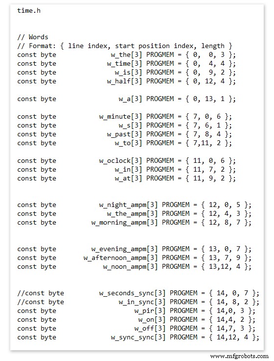
On line 52 we have
const byte w_the[3] PROGMEM ={ 0, 0, 3 };
The word "THE" is described in this line with the LED location in the curly brackets "{ 0, 0, 3 }"
This is the co-ordinate of the LEDs we are gong to light when we call "w_the"
The LED matrix numbers starts top left and start from 0 so "{ 0, 0, 3 }" is the first LED across and down the 3 just means the 3 LEDs across including this one will light. As the letters THE are in this position the word "THE" is displayed.
Similarly the word "TIME" would be lit by lighting the four LEDs here { 0, 4, 4 } or row 0, 5th LED along and light 4 LEDs (remember to count from 0).
Working you way down the page shows the position of all the words.
Controlling when words are lit
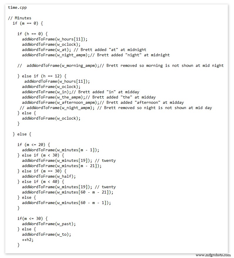
This happens in the module time.cpp
Here you just make a list of rules to tell the clock what words to light at certain times.
Pic above shows part of the code starting with line 695
At midnight we want to make the clock say "THE TIME IS TWELVE OCLOCK AT NIGHT"
Midnight is 00 00
"THE TIME IS" is always displayed from lines 687
So we add the rules if minutes are 0, then if hours are 0 show the word for hours "TWELVE" and the word "OCLOCK" the word "AT" and the word "NIGHT"
If you follow the code down all the possible time combinations are covered.
Analogue Clock Code Change - increase in time definition One of the comments sent to me by srdevil was some code changes. His comment can be seen below.
I have not had time to test the code but have included it below if you want to try it out.
" If the time is 18:00, it points up (long leg) and down (short leg). But when the time is 18:59, it still points totally down (short leg) so it looks like the time is 17:59 on a normal clock. My brother change the code so that if it is>HH:15 the small pointer moves already to the next number. As of this we also increased the resolution in the part between>HH:15 -
Code on the comments section or can be seen here http://home.btconnect.com/brettoliver1/Word_Clock/Word_Clock.htm#analogeclock
代码
- Brett_wordclock_v4_5.zip
Brett_wordclock_v4_5.zipArduino
Load into Aduino IDENo preview (download only).
Github
https://github.com/wouterdevinck/wordclockhttps://github.com/wouterdevinck/wordclockGithub
https://github.com/svcabre/wordclockhttps://github.com/svcabre/wordclockMy Word Clock on GITHUB
Schematics and code https://github.com/brettoliver/wordclock定制零件和外壳
Vinyl Sticker Design in Inkscape (free to download) change as required brett11_print_ready_6bbpMTDyFa.svg示意图
Schemaic showing main board connections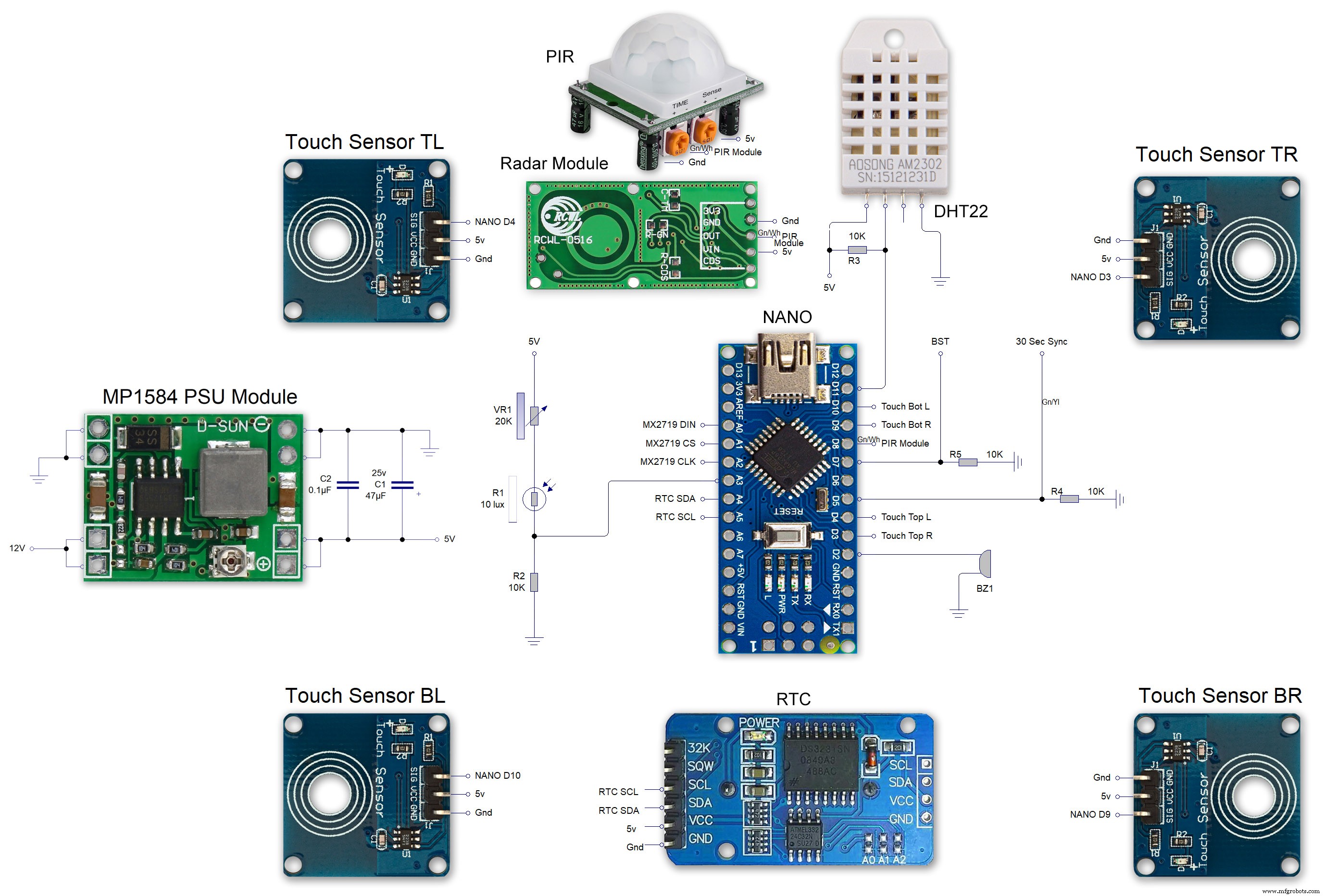 MAX7219 7 segment display module 01 LED connections
 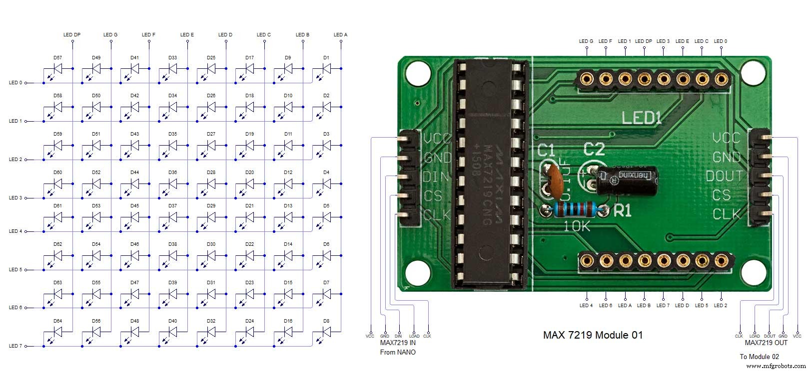 MAX7219 7 segment display module 02 LED connections
 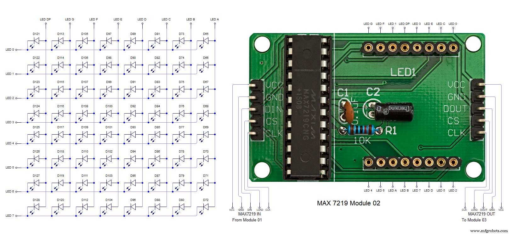 MAX7219 7 segment display module 03 LED connections
 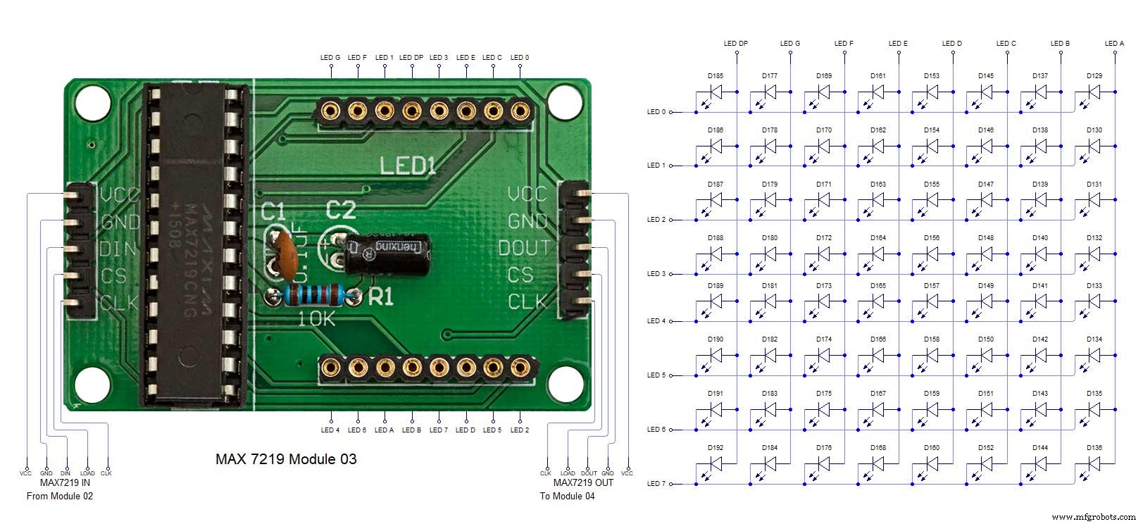 MAX7219 7 segment display module 04 LED connections
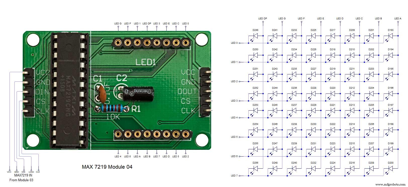
制造工艺