

如何在 VHDL 中创建有限状态机
有限状态机(FSM)是一种机制,其输出不仅取决于输入的当前状态,还取决于过去的输入和输出值。
每当你需要在 VHDL 中创建某种时间相关的算法,或者遇到在 FPGA 中实现计算机程序的问题时,通常可以使用 FSM 来解决。
VHDL 中的状态机是时钟进程,其输出由状态信号的值控制。状态信号用作上一次迭代中发生的事情的内部记忆。
这篇博文是基本 VHDL 教程系列的一部分。
考虑这个路口的红绿灯状态:
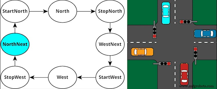
交通信号灯有有限数量的状态,我们已经给了可识别的名称。我们的示例状态机没有控制输入,输出是北/南和西/东方向的灯光状态。推进这个状态机的是经过的时间和输出的先前状态。
我们可以使用 枚举类型 在 VHDL 中表示状态 .这些是类似于 signed 的数据类型 或 unsigned ,但我们可以提供可能值的自定义列表,而不是整数。事实上,如果你看一下std_logic_1164包,你会发现std_ulogic type 只不过是一个枚举类型,其值为 'U' , 'X' , '0' , '1' , 'Z' , 'W' , 'L' , 'H' , 和 '-' 列为枚举值。
一旦我们有了枚举类型,我们就可以声明一个新类型的信号,该信号可用于跟踪 FSM 的当前状态。
VHDL中用枚举类型声明信号的语法是:type <type_name> is (<state_name1>, <state_name2>, ...);
signal <signal_name> : <type_name>;
使用状态信号,有限状态机可以在一个带有 Case 语句的过程中实现。 Case 语句包含每个可能状态的 When 语句,导致程序为每个状态采用不同的路径。 When 语句还可以包含应在该特定状态下执行的代码。然后,当满足预定义的条件时,状态通常会发生变化。
这是一个单进程状态机的模板:process(Clk) is
begin
if rising_edge(Clk) then
if nRst = '0' then
State <= <reset_state>;
else
case State is
when <state_name> =>
<set_outputs_for_this_state_here>
if <state_change_condition_is_true> then
State <= <next_state_name>;
end if;
...
end case;
end if;
end if;
end process;
注意:
有几种方法可以在 VHDL 中创建 FSM。在此处了解不同的样式:
单进程、两进程与三进程状态机
运动
在本视频教程中,我们将学习如何在 VHDL 中创建有限状态机:
状态机 testbench 的最终代码 :
library ieee;
use ieee.std_logic_1164.all;
use ieee.numeric_std.all;

entity T20_FiniteStateMachineTb is
end entity;

architecture sim of T20_FiniteStateMachineTb is

    -- We are using a low clock frequency to speed up the simulation
    constant ClockFrequencyHz : integer := 100; -- 100 Hz
    constant ClockPeriod : time := 1000 ms / ClockFrequencyHz;

    signal Clk         : std_logic := '1';
    signal nRst        : std_logic := '0';
    signal NorthRed    : std_logic;
    signal NorthYellow : std_logic;
    signal NorthGreen  : std_logic;
    signal WestRed     : std_logic;
    signal WestYellow  : std_logic;
    signal WestGreen   : std_logic;

begin

    -- The Device Under Test (DUT)
    i_TrafficLights : entity work.T20_TrafficLights(rtl)
    generic map(ClockFrequencyHz => ClockFrequencyHz)
    port map (
        Clk         => Clk,
        nRst        => nRst,
        NorthRed    => NorthRed,
        NorthYellow => NorthYellow,
        NorthGreen  => NorthGreen,
        WestRed     => WestRed,
        WestYellow  => WestYellow,
        WestGreen   => WestGreen);

    -- Process for generating clock
    Clk <= not Clk after ClockPeriod / 2;

    -- Testbench sequence
    process is
    begin
        wait until rising_edge(Clk);
        wait until rising_edge(Clk);

        -- Take the DUT out of reset
        nRst <= '1';

        wait;
    end process;

end architecture;
状态机模块的最终代码 :
library ieee;
use ieee.std_logic_1164.all;
use ieee.numeric_std.all;

entity T20_TrafficLights is
generic(ClockFrequencyHz : integer);
port(
    Clk         : in std_logic;
    nRst        : in std_logic; -- Negative reset
    NorthRed    : out std_logic;
    NorthYellow : out std_logic;
    NorthGreen  : out std_logic;
    WestRed     : out std_logic;
    WestYellow  : out std_logic;
    WestGreen   : out std_logic);
end entity;

architecture rtl of T20_TrafficLights is

    -- Enumerated type declaration and state signal declaration
    type t_State is (NorthNext, StartNorth, North, StopNorth,
                        WestNext, StartWest, West, StopWest);
    signal State : t_State;

    -- Counter for counting clock periods, 1 minute max
    signal Counter : integer range 0 to ClockFrequencyHz * 60;

begin

    process(Clk) is
    begin
        if rising_edge(Clk) then
            if nRst = '0' then
                -- Reset values
                State   <= NorthNext;
                Counter <= 0;
                NorthRed    <= '1';
                NorthYellow <= '0';
                NorthGreen  <= '0';
                WestRed     <= '1';
                WestYellow  <= '0';
                WestGreen   <= '0';

            else
                -- Default values
                NorthRed    <= '0';
                NorthYellow <= '0';
                NorthGreen  <= '0';
                WestRed     <= '0';
                WestYellow  <= '0';
                WestGreen   <= '0';

                Counter <= Counter + 1;

                case State is

                    -- Red in all directions
                    when NorthNext =>
                        NorthRed <= '1';
                        WestRed  <= '1';
                        -- If 5 seconds have passed
                        if Counter = ClockFrequencyHz * 5 -1 then
                            Counter <= 0;
                            State   <= StartNorth;
                        end if;

                    -- Red and yellow in north/south direction
                    when StartNorth =>
                        NorthRed    <= '1';
                        NorthYellow <= '1';
                        WestRed     <= '1';
                        -- If 5 seconds have passed
                        if Counter = ClockFrequencyHz * 5 -1 then
                            Counter <= 0;
                            State   <= North;
                        end if;

                    -- Green in north/south direction
                    when North =>
                        NorthGreen <= '1';
                        WestRed    <= '1';
                        -- If 1 minute has passed
                        if Counter = ClockFrequencyHz * 60 -1 then
                            Counter <= 0;
                            State   <= StopNorth;
                        end if;

                    -- Yellow in north/south direction
                    when StopNorth =>
                        NorthYellow <= '1';
                        WestRed     <= '1';
                        -- If 5 seconds have passed
                        if Counter = ClockFrequencyHz * 5 -1 then
                            Counter <= 0;
                            State   <= WestNext;
                        end if;

                    -- Red in all directions
                    when WestNext =>
                        NorthRed <= '1';
                        WestRed  <= '1';
                        -- If 5 seconds have passed
                        if Counter = ClockFrequencyHz * 5 -1 then
                            Counter <= 0;
                            State   <= StartWest;
                        end if;

                    -- Red and yellow in west/east direction
                    when StartWest =>
                        NorthRed   <= '1';
                        WestRed    <= '1';
                        WestYellow <= '1';
                        -- If 5 seconds have passed
                        if Counter = ClockFrequencyHz * 5 -1 then
                            Counter <= 0;
                            State   <= West;
                        end if;

                    -- Green in west/east direction
                    when West =>
                        NorthRed  <= '1';
                        WestGreen <= '1';
                        -- If 1 minute has passed
                        if Counter = ClockFrequencyHz * 60 -1 then
                            Counter <= 0;
                            State   <= StopWest;
                        end if;

                    -- Yellow in west/east direction
                    when StopWest =>
                        NorthRed   <= '1';
                        WestYellow <= '1';
                        -- If 5 seconds have passed
                        if Counter = ClockFrequencyHz * 5 -1 then
                            Counter <= 0;
                            State   <= NorthNext;
                        end if;

                end case;

            end if;
        end if;
    end process;

end architecture;
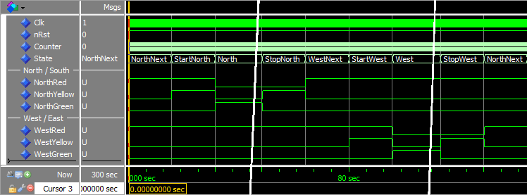
我们输入run 5 min后的波形 ModelSim 控制台中的命令:
分析
我们声明了一个枚举类型,其中包含交通灯的所有八种不同状态。然后,我们声明了一个 state 我们创建的这种新类型的信号。这意味着信号只能具有八个命名状态值之一,而不能具有其他值。
FSM 是使用时钟进程中的 Case 语句实现的。在时钟的每个上升沿,进程唤醒,state 信号被评估。 when 之一内的代码 允许选择(分支)运行,具体取决于当前状态。
在我们的代码中,它是 Counter 的值 触发状态变化的信号。当 Counter 达到预定义的值(表示 5 秒或 1 分钟)时,会将新的状态编码分配给 State 信号。然后,当状态值更新后进程在时钟的下一个上升沿唤醒时,FSM处于不同的状态。
请注意,我们没有分配 '0' 到任何 when 中的任何信号 选择。这是因为我们给所有的输出信号一个默认值 '0' 在过程的开始。您可能记得在之前的教程中,它是分配给生效信号的最后一个值。信号分配只有在进程终止后才会生效。如果我们分配 '0' 到进程开始时的信号,然后是 '1' 在 when 之一中 选择,信号将获得值 '1' .
从波形中我们可以看出State 信号循环通过八个状态。稳定的绿色状态持续一分钟,因此波形图像已被剪切到 North 和 West 州。

外卖
- 算法通常以有限状态机 (FSM) 的形式实现
- 可以通过在时钟进程中使用 case 语句来实现 FSM
- FSM 状态可以以枚举类型实现
转到下一个教程 »
VHDL