

NEMA 电机。最常见的问题
电机是任何 FFF 3D 打印机的基本组件之一。它们负责进行必要的移动以定位打印头,以及拉动挤出机中的灯丝。
使用的电机是步进电机,最常见的类型是NEMA 17和NEMA 23。
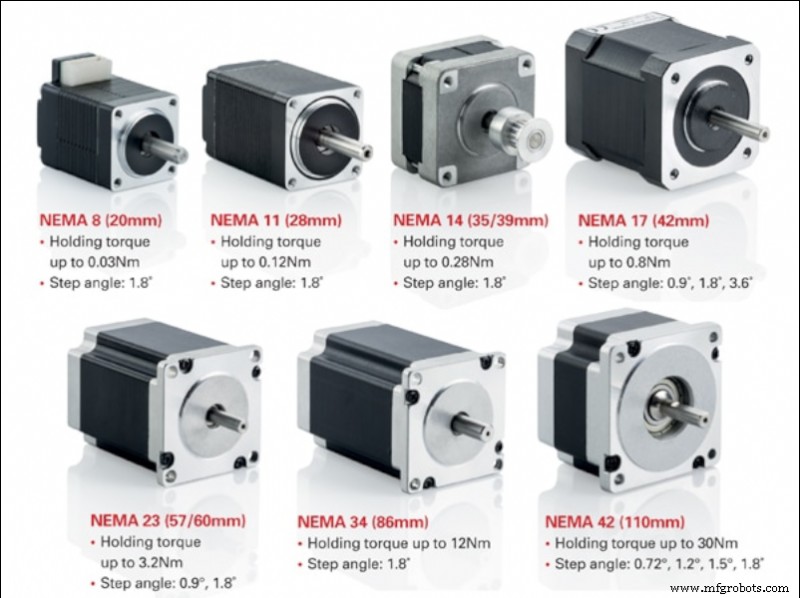
图 1:NEMA 电机的类型。来源:motioncontrolproducts.com
质量好的步进电机具有非常高的可靠性,因此电机故障的主要原因通常是外部原因,通常与电源驱动器或连接有关。
步进电机
步进电机是一种连续旋转的电机。旋转发生在给定角度的离散跳跃中。它是介于标准直流电机和伺服电机之间的电机。与直流电机一样,它们允许多次 360° 转动,同时允许精确的角度定位,如伺服电机。
3D 打印机中最常用的是双极混合式步进电机,通常为 NEMA17 或 NEMA23 格式。混合电机结合了 VR 电机的小步进能力和永磁电机的高惯性能力。另一方面,双极电机比单极电机具有更高的扭矩和锚定性,同时重量更轻、尺寸更小,但需要特定的功率控制器。
选择步进电机时,我们必须知道它的主要特点:
- 步骤: 这是电机可以直接旋转的最小角度(不使用微步控制器)。我们通常可以找到步距为 1.8 º 或 0.9 º 的电机。一般来说,步幅越小意味着精度越高,但最大转速也越低。
- 工作电流: 这是我们必须为电机供电以使其正常工作的最大电流值。我们施加到电机的电流越大,我们将获得越大的扭矩,因此它能够承受更大的惯性而不会失步,但是,也会产生更大的热量和磨损。使用高于制造商规定的电流会导致电机性能下降和故障。
- 每相电压: 这是每个线圈正常运行所需的电压。
- 相电阻: 这是每个线圈提供的电阻。
- 相电感: 每个线圈在激活时产生的最大电感值。
- 定位精度: 旋转运动期间可能发生的最大偏差。通常,较低的值表示较高的准确度。
- 最高工作温度: 这是电机可以承受的最高工作温度。长时间超过此温度会导致电机故障。
- 转子惯性: 这是转子空载时由于其自身重量而提供的惯性。电机支持的惯性将是这个加上耦合到电机的元件的总和。
- 扭矩或保持扭矩: 这是当相位处于非活动状态(无电流)时电机可以承受的最大扭矩,不会导致轴旋转。
- 锚力矩: 这是电机在停止且相位处于活动状态(带电)时可以承受的最大扭矩,不会导致轴旋转。该值是针对提供最大电流的电机考虑的。
- 启动扭矩: 这是克服转子惯性使其开始旋转所需的扭矩。
- 转动扭矩: 这是电机在旋转时可以承受的最大扭矩,不会造成失步。该值是针对提供最大电流的电机考虑的。
如果我们正在寻找一种允许我们在运动过程中使用高速和承受高惯性的电机,例如在 XY 轴的情况下,我们应该选择具有 1.8 º 步距和高扭矩的电机。
Z 轴电机不需要高工作速度,因此 0.9 º 电机将提供更平稳的运动。在这种情况下,应选择具有最大保持和锚定扭矩的电机来支撑平台或龙门架的重量(取决于打印机的设计)。
双极步进电机的连接
正确连接步进电机时,提供制造商的规格表很有用,因为电线的位置因型号而异。
通常,双极步进电机有 4 个连接,由两个独立的电源电路组成。每个电路由一个正极和一个负极组成,为电机的每个线圈供电。
首先要知道这四个连接在我们的打印机控制板上的位置。我们可以在控制板上找到两种类型的命名法。第一个是 1A 1B 2A 2B,其中每个数字代表一个电路,字母 A 和 B 代表极点。第二个是 A A - B B - 其中每个字母代表一个电路,重音符号代表负极。
确定电路板上的连接后,必须对电机进行相同的连接。
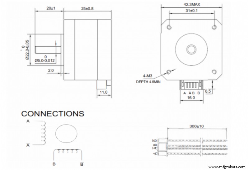
图 2. NEMA17 电机规格表上的连接示例。来源:邦德科技
如果有规格表可用,则应查阅连接器中电线的顺序。在这种情况下,命名 A A - B B - 是最常见的。
在电路板和电机使用相同命名法的情况下,连接就像配对每个端子一样简单。如果它们使用不同的命名法,它们必须按如下方式配对:
- 1A - A
- 1B - A -
- 2A - B
- 2B - B -
如果没有可用的电机数据表,则必须确定每个阀芯的连接对。这是通过测量连接器引脚对的所有可能组合的电阻来完成的。当电阻不是无穷大时,第一对已经定位。电机制造商最常用的组合是 1-3 4-6 或 1-4 3-6,因此请先测试这两种组合。
一旦定位,每个相位都连接到每个线轴。重要的是两相以相同的极性连接到线圈,所以如果我们将它们反相放置,当向电机发送电流时它不会移动并且会发出噪音。在这种情况下,其中一个线圈的极性必须反转。
保持两相分离非常重要,因此应经常检查连接器的状况。相间接触不良或桥接会导致电机停止工作。
设置电机电流
步进电机通过特定的控制器或驱动器供电。市场上有许多不同的型号。质量越高的通常会提供更长的耐用性和更安静的操作。
在可用的模型中,有两种方法可以调整发送到电机的电流:
- 通过调节螺钉。 通常,质量较低或较便宜的驱动器允许通过螺钉形式的电位计来调节输出电流。这种情况下就需要使用万用表和精密陶瓷螺丝刀进行调整。
这种情况下可以通过两种方式进行调整:
- 按电流:在打印机开启并连接电机的情况下,将测量其中一相的电流并将其调整为适当的值。不推荐这种方法,尤其是在第一次连接新驱动器时,因为电机最初是在不知道输出电流是否高于电机允许的电流的情况下启动的。
- By reference voltage:This is a slightly more complex method, but more recommendable. First we must determine the required reference voltage using the formula:
max · 8 · Rs
Where Imax is the maximum current at which the motor will be powered (usually at most 90 % of the maximum specified by the manufacturer) and Rs is the detection resistance of the driver.
To adjust it on the driver, simply power up the driver, measure the voltage between the Vref pin (usually the potentiometer itself) and a ground pin (usually the power supply pin) and set the appropriate value using the potentiometer.
- By firmware: Many current drivers do not have an adjustment potentiometer and allow the output current to be set directly by firmware. To do this, simply set the appropriate current value in the motor section of the firmware.
When selecting the output current of the drivers, it is not advisable to use the maximum value determined by the manufacturer. In order to prolong the service life of the motors, do not exceed 90 % of the manufacturer's maximum value, the optimum being the minimum current required to generate sufficient torque to withstand the inertias.
Higher current, in addition to higher torque, also means higher heating, higher motor noise and higher wear.
Maximum speed of a stepper motor
Stepper motors advance by pulses, so the maximum speed of the motor will depend on the maximum signal frequency that the control board is able to send. In addition, it must be taken into account that usually several motors are working simultaneously, so the frequency for each one will decrease.
For example, if the control board works at 100000 Hz and 4 motors (X,Y,Z and extruder) are working simultaneously, each motor will be controlled at 25000 Hz, or 25000 pulses per second. This means that a 1.9 ° motor without microstepping can rotate at a maximum of 125 rps. In a GT2 8-tooth belt drive system (the most common) this translates into a theoretical maximum linear speed of 3600 mm/s.
In the case of microstepping, the maximum speed would be reduced proportionally, so that if 16 microsteps are used, the maximum speed would be 225 mm/s, but if 256 microsteps are used, it would be reduced to only 14 mm/s.
It is very important to know the operating frequency of the control board, as the combination of a low output frequency with a high microstep setting can cause the maximum allowable speed to be lower than the printing speed, resulting in a significant loss of steps.
Appropriate setting of the steps per mm
When the motion signal is transmitted to the motor, it is sent as a rotation, however the movements included in the print files are linear. This is why the printer must be able to translate the angular movement into a linear one.
The movement is generally transmitted by means of toothed pulleys and belts, so that the step/mm conversion depends on the diameter of the pulleys.
To calculate this, the following formula is simply applied:
steps/mm = (360/P) · MS
2 · π · Rpulley
Where P is the motor pitch, MS the configured microsteps (1 in case of not using microstepping) and Rpulley the radius of the pulley used.
In the case of screw-transmitted movements, it is the pitch of the screw that defines the feed rate. For this purpose, the following formula is simply applied:
steps/mm = (360/P) · MS
A
Where P is the motor pitch, MS the configured microsteps (1 in case of not using microstepping) and A the pitch of the screw thread.
There are also many calculators that make it easier to obtain these values, such as the one offered by Prusa Printers.
Once these values have been obtained, and although in theory they are correct, it is advisable to carry out a precise calibration to compensate for possible manufacturing or assembly defects.
For this purpose, a cube of known dimensions (e.g. 50 x 50 x 50 mm) shall be printed out and the actual dimensions measured. Once this is done, the following formula shall be applied:
steps/mm = Dtheorical · Pactual
Dreal
where Dtheorical is the theoretical size that the part should have, Pactual is the current P/mm setting and Dreal is the measurement value obtained from the printed part.
By introducing the new P/mm value, you should obtain parts with appropriate dimensions.
Considerations to take into account
- Step loss: A step loss is usually caused by excessive torque in the engine. Large accelerations or high direction change speeds will cause inertias that the motor torque cannot compensate for, resulting in a step loss. Similarly, the combination of low signal frequencies and high microstep settings will drastically reduce the maximum motor speed. If the print speed exceeds this, a step loss will also occur. In any case, step loss in an open-loop printer will result in loss of position.
- Temperature: A high current setting will cause the motor to heat up. If the motor is inside a closed or heated structure that does not allow the heat to dissipate correctly, the working temperature may be exceeded, causing the demagnetisation of the magnets and a malfunction or breakdown of the motor. In closed printers, it is advisable to place the motors outside the chamber or, if this is not possible, to reduce the current to the minimum necessary.
- Hysteresis: This is a phenomenon intrinsic to motors. It can cause a small position error at the end of a movement. Using quality motors will reduce this error.
- Resonance: All motors have a natural frequency. If the pulse frequency sent to the motor is similar to the natural frequency, a resonance effect will occur. This will cause increased vibration, noise and wear.
- Step settings: Improper step/mm settings will result in positioning error, which will be reflected in dimensional errors in the parts.
- Connection: Mixing or bridging phases will cause the motor to not turn or to turn erratically. Placing one phase with the polarity reversed with respect to the other will cause the motor not to turn. Reversing the polarity of both phases, when connected correctly, will cause the motor to rotate in the opposite direction.
This guide discusses concepts in a general way and does not focus on a particular make or model, although they may be mentioned at some point. There may be important differences in calibration or adjustment procedures between different makes and models, so it is recommended that the manufacturer's manual be consulted before reading this guide.
3D打印