

伴侣 IC
组件和用品
 |
| × | 1 | |||
 |
| × | 1 | |||
 |
| × | 4 | |||
 |
| × | 1 | |||
 |
| × | 2 | |||
 |
| × | 3 | |||
 |
| × | 4 | |||
 |
| × | 2 | |||
 |
| × | 1 | |||
 |
| × | 1 |
必要的工具和机器
 |
| |||
 |
|
关于这个项目
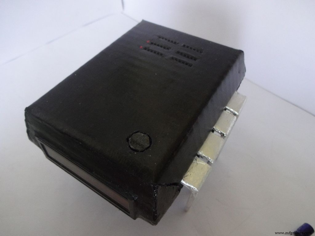

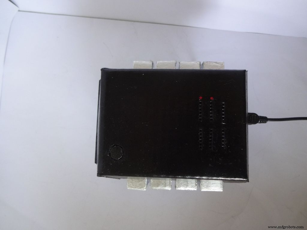
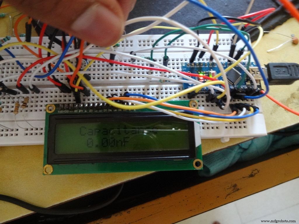
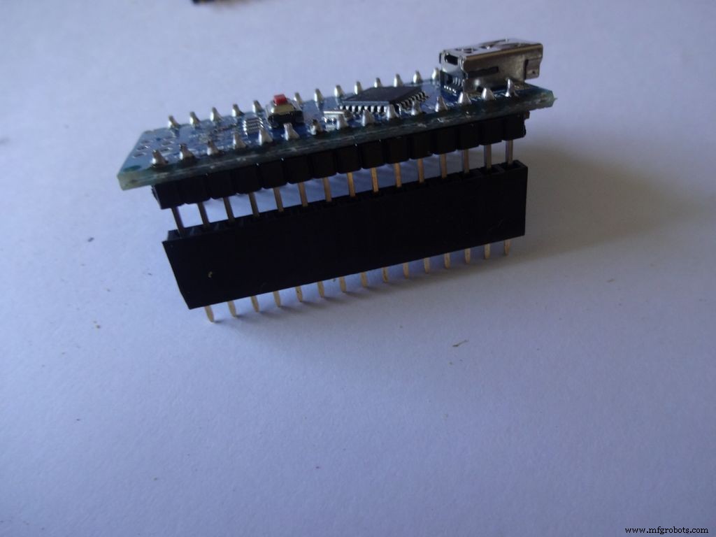
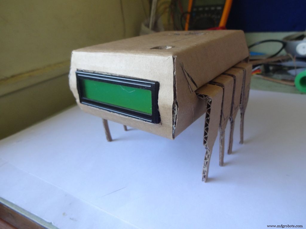
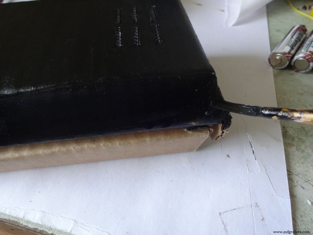
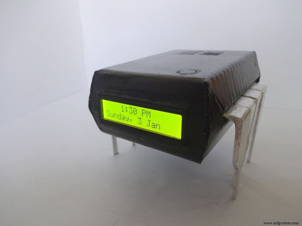
配套 IC 是一款外观非常酷的时钟 + 欧姆表 + 电容表 + 二极管测试仪!按下 IC 的引脚 1 将其打开!将它放在您的工作台上,以便快速测试组件和检查时间。如果工作台附近有电源,可以使用电池或 USB 供电。
我一直想发布一个项目,但直到现在才发现任何独特的东西!当我想测试一些电容器以查看它们是否有故障时,我想到了这个想法。我只有一个万用表,它没有电容测量功能。搜索之后,我才知道 Arduino 可以做到这一点。我决定自己做一个,但看到 Arduino 上未使用的引脚并不是很令人满意,所以我决定添加一个自动量程欧姆表、快速 LED/二极管测试仪和 RTC 时钟!我还希望它通过插入组件而不使用任何探针来直接测量值。设计必须是独一无二的,所以经过一些头脑风暴后,IC 设计就完成了!
编辑(07/01/2016):添加了可选的连续性测试,请参阅评论部分。
这篇文章非常详细地解释了我是如何制作这个的,以及你也可以如何自己制作。它是初学者友好的,任何拥有 2-3 周 Arduino/电子学经验的人都可以构建它!
该设计是可修改的,您可以根据您的要求删除/添加新功能。我是用纸板做的,但如果你有技能,你可以用木头或 3D 打印它。
我试图在我所做的每一步都拍照并附上照片(每一步都有很多!)。其中大部分拍摄了多次,直到我获得最佳角度/光线,但仍有一些有点模糊,因为用两只手握住它们有时很困难。
我已经分解了整个代码和布线,就像我是如何做到的一样。包含的代码被大量注释并正确缩进。随着我们继续前进。我们将一步一步地结合所有代码和布线来创建最终的 IC。这应该有助于任何人清楚地理解它。如果没有,请在评论中告诉我。
即使你决定不做,也可以在面包板上试一试,或者至少通读一遍,因为一定有一些方法或技巧或一些你可以在这里学习并且有一天会对你有用的东西(说真的,你永远不知道什么时候它点击!)
第 1 步:所需的工具和组件
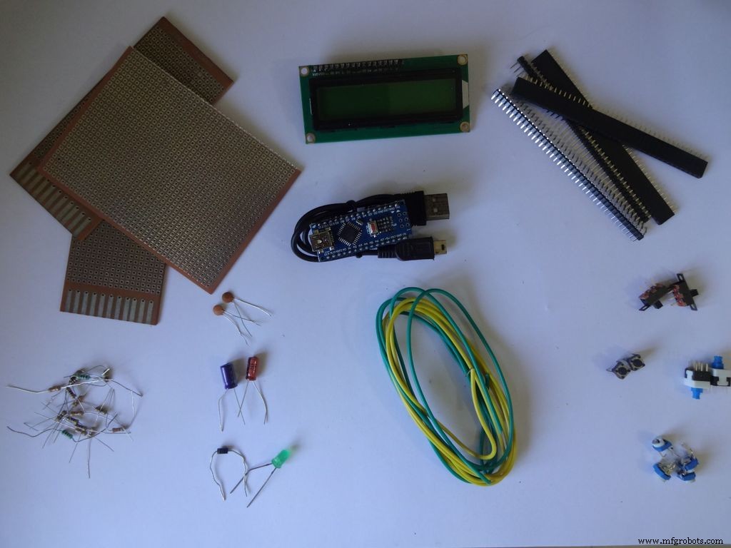

使用的组件和材料列表(商店链接仅供参考):
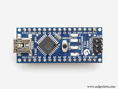
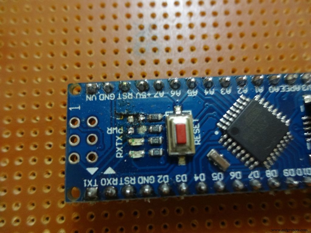
- 1x Arduino Nano V3, 我使用了 CH340G 的克隆 -- 易趣
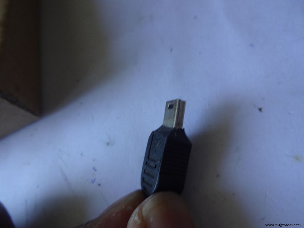
- 迷你 USB 数据线 适用于 Arduino Nano -- Mini 不是微 !
- 纸板 -- 我用了一个包装盒,厚度~2mm。问问你的邻居、朋友,如果找不到就去捡。
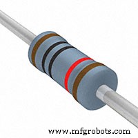
- 4x 10k 欧姆电阻 -- 容易获得
- 2x 220 欧姆电阻 -- 容易获得
- 1x (1k、4.7k、47k、100k)欧姆电阻 -- 容易获得
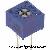
- 1x 小型 10k 欧姆电位器, 用于 LCD 的对比度控制...任何小尺寸的都可以使用 .--易趣
- 2 个微型 按钮, 用于重置和模式更改按钮,这些按钮是您在面包板上常用的按钮。
- 3 个小型 滑动开关 , 用于启用背光,引脚 0 和 1,使用串行时需要禁用这些引脚 -- 易趣
- 1x 维护/切换/锁定按钮开关, 电源开关 -- 易趣
- 一些电容器、二极管、LED 仅用于测试,总有一天你会用到它们。
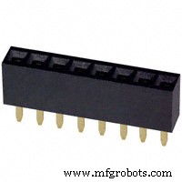
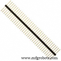
- 4x 母头针脚带 -- ebay(每条 40 针)
- 2x 公头针脚带 -- ebay(每条 40 针)
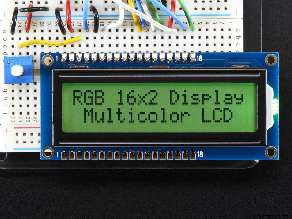
- 1x 16x2 字符 LCD -- 易趣
- 1x DS3231 或 DS1307 RTC 模块 (RTC 代表实时时钟)——不要从 ebay 购买便宜的。这些使用假芯片并且不准确。买这个,这个或这个。其中任何一个都可以。
- 4 节 AA 电池 (或 AAA。 使用 AAA 会容易得多,但电池容量较小)
- 1x 4 AA(或 AAA)电池座 , 扁平变体 -- 易趣
- 单股线 , 用于面包板的那些,22 guage
- 带状电缆 (或者可以使用一些细的双绞线) -- 易趣
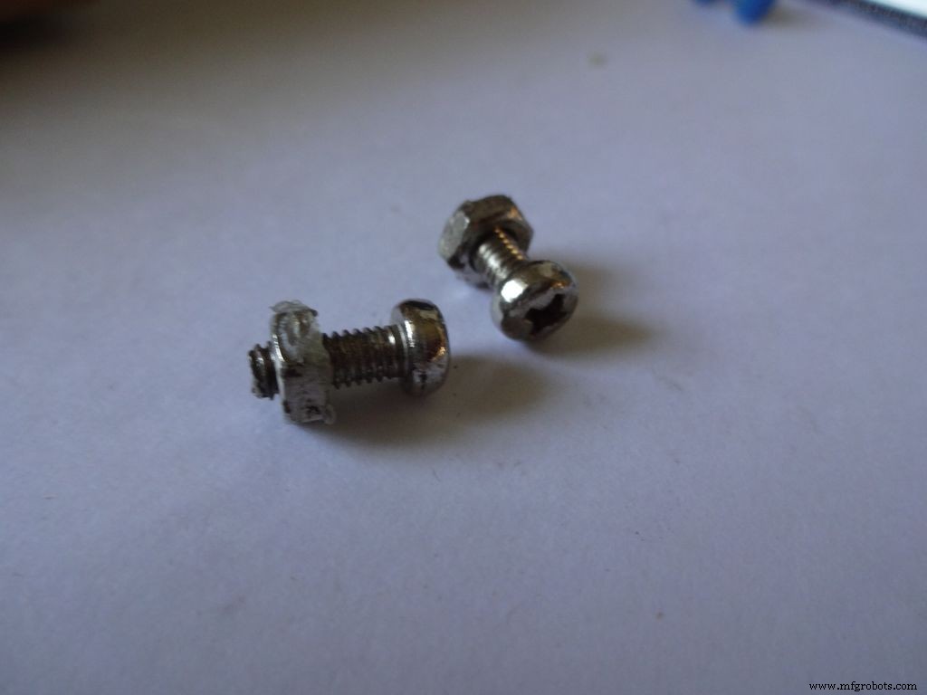
- 2x 小螺母和螺栓 -- 我使用了旧 Meccano 套装中的那些(螺栓长 1.3 厘米)
- 黑色丙烯颜料和刷子
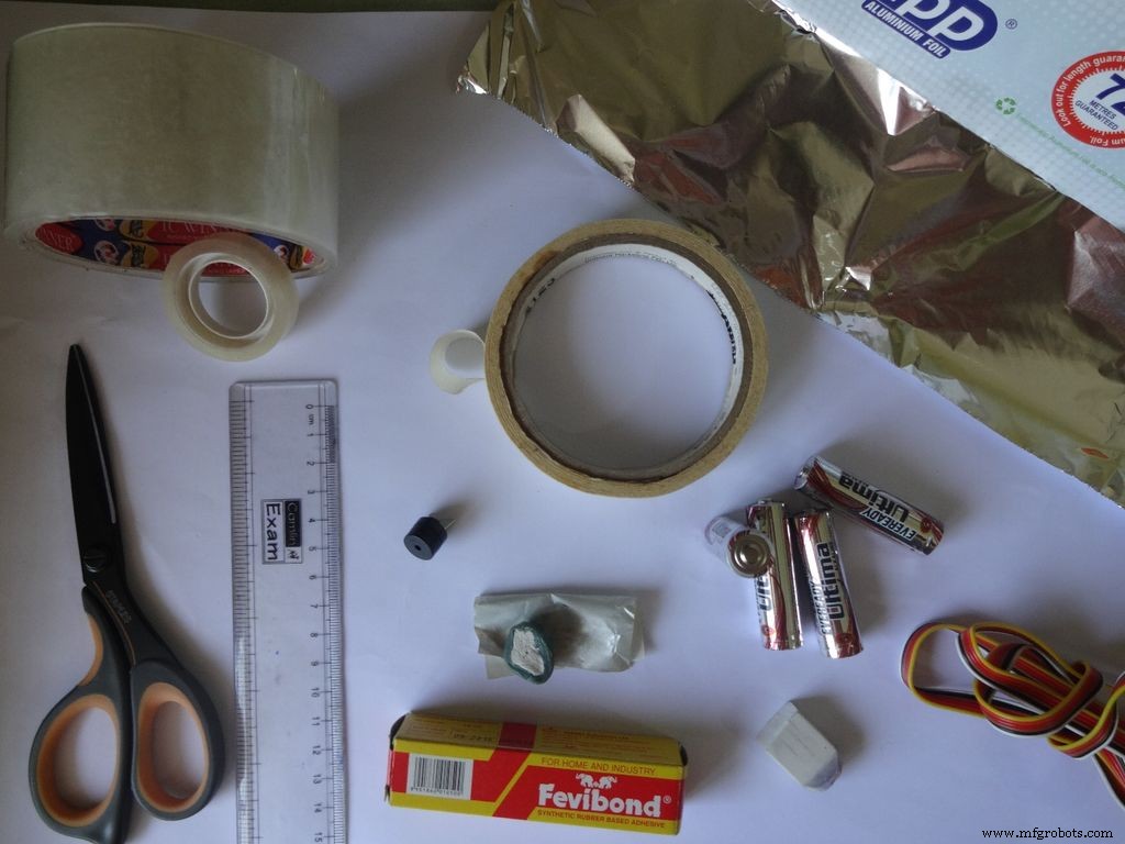
所需工具:
- 烙铁
- 焊锡
- 拆焊灯芯/编织物(因为当你搞砸了!)
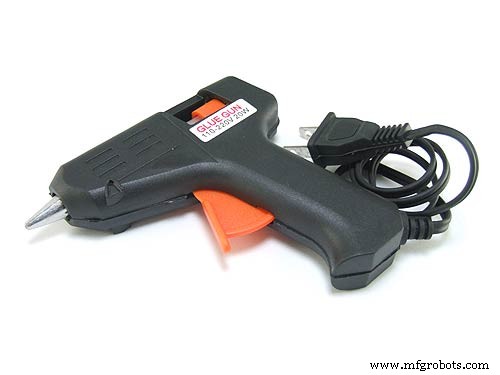
- 胶枪
- 胶带
- 大提琴胶带,透明
- 剥线钳、钳子
- 锋利的盒式切割机
- 锋利的剪刀
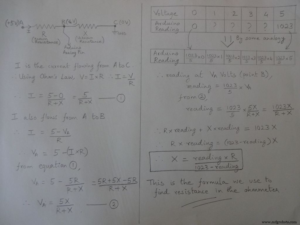
第 2 步:欧姆表 - 概念
测量电阻的基本思想来自分压器。
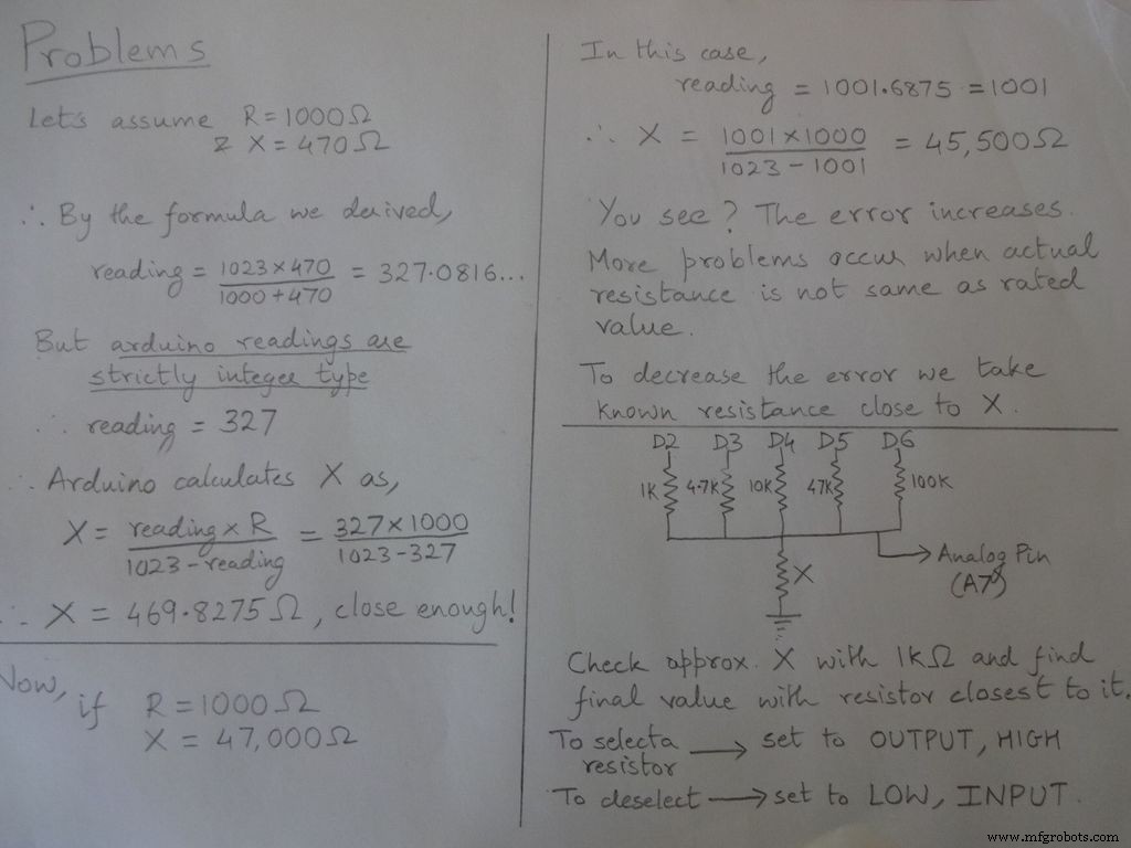
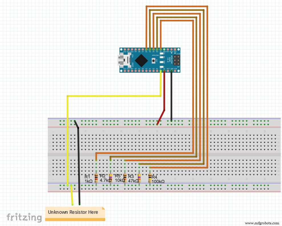
电阻值是可修改的,改变 r1、r2 等的值。也相应地设置量程(用于自动量程)。见下面的代码,从最后的文件中下载并在面包板上测试欧姆表
如果您是第一次设置 Nano,可以在此处下载 CH340G 驱动程序,适用于 Windows 7、8、8.1 和 10。Mac 用户在此处查看。
在板菜单和正确的 COM 端口中选择“Arduino Nano”。上传!
代码
//用于求电阻的模拟引脚int Apin=7;//r1到r5的值float r1=1000;float r2=4700;float r3=10000;float r4=47000;float r5=100000;/ /pins of r1 to r5int r1_pin=2;int r2_pin=3;int r3_pin=4;int r4_pin=5;int r5_pin=6;float reading=0; //从模拟引脚读取并存储在这里float R=0; //计算未知并存储在这里String finalR; //与unitsint caseno一起显示的最终值; // 用于调试,存储案例编号 // 我们将整个范围划分为案例并为每个案例分配一个数字,总共 5 个案例 // case1 :小于 2850 // case2 :2850 到 7350 // case3 :7350 到 28500 // case4 :28500 to 73500 // case5 :more than 73500#include // 需要将浮点数转换为字符串,有 String(float,n) 函数。下面解释。void setup() { Serial.begin(9600);}void loop() { //首先我们使用1kOhm电阻找到未知电阻//因此,禁用R2、R3、R4和R5 digitalWrite(r2_pin, LOW); //在将每个引脚设置为INPUT pinMode(r2_pin, INPUT)之前将其设为低电平; // 当它的高电平启用内部上拉电阻时将其转为 INPUT digitalWrite(r3_pin, LOW); pinMode(r3_pin,输入);数字写入(r4_pin,低); pinMode(r4_pin,输入);数字写入(r5_pin,低); pinMode(r5_pin,输入); pinMode(r1_pin,输出);数字写入(r1_pin,高); //读取并计算电阻读数=analogRead(Apin); R=(读数*r1)/(1023-读数); // 如果 value <2850, finalR =value(使用 1kOhm) if(R<2850){ caseno=1; if(R<1000){ //如果值小于 1000 使用 "Ohm" 而不是 "kOhm" finalR =String(R,2) + "Ohm"; //String(float,n) 将浮点数转换为小数点后有 n 位数字的字符串 // 在 value 后附加 "Ohm" 到字符串,'+' 在这里连接两个字符串 } else{ // 使用 "kOhm R=R/1000; finalR =String(R,2) + "kOhm"; } } //如果值在 2850 和 7350 之间,使用 4.7kOhm 得到的值 else if(R>=2850 &&R<7350){ caseno=2; digitalWrite(r1_pin , LOW); //仅启用 4.7kOhm pinMode(r1_pin, INPUT); digitalWrite(r3_pin, LOW); pinMode(r3_pin, INPUT); digitalWrite(r4_pin, LOW); pinMode(r4_pin, INPUT); digitalWrite(r5_pin, LOW) ); pinMode(r5_pin, INPUT); pinMode(r2_pin, OUTPUT); digitalWrite(r2_pin, HIGH); reading=analogRead(Apin); R=(reading*r2)/(1023-reading)/1000; finalR =String( R,2) + "kOhm"; } //如果值在7350到28500之间,使用10kOhm得到的值 else if(R>=7350 &&R<28500){ caseno=3; digitalWrite(r1_pin, LOW); pinMode( r1_pin, INPUT); digitalWrite(r2_pin, LOW); pinMode(r2_pin, INPUT); digitalWrite(r4_pin, LOW); pinMode(r4_pin, INPUT); digitalWrite(r5_pin, LOW); pinMode(r5_pin, INPUT); pinM ode(r3_pin,输出);数字写入(r3_pin,高);阅读=模拟阅读(Apin); R=(读数*r3)/(1023-读数)/1000; finalR=String(R,2) + "kOhm"; } //如果值在28500和73500之间,使用47kOhm得到的值 else if(R>=28500 &&R<73500){ caseno=4;数字写入(r1_pin,低); pinMode(r1_pin,输入);数字写入(r2_pin,低); pinMode(r2_pin,输入);数字写入(r3_pin,低); pinMode(r3_pin,输入);数字写入(r5_pin,低); pinMode(r5_pin,输入); pinMode(r4_pin,输出);数字写入(r4_pin,高);阅读=模拟阅读(Apin); R=(读数*r4)/(1023-读数)/1000; finalR =String(R,2) + "kOhm"; } //如果值大于73500,使用100kOhm得到的值 else if(R>=73500){ caseno=5;数字写入(r1_pin,低); pinMode(r1_pin,输入);数字写入(r2_pin,低); pinMode(r2_pin,输入);数字写入(r3_pin,低); pinMode(r3_pin,输入);数字写入(r4_pin,低); pinMode(r4_pin,输入); pinMode(r5_pin,输出);数字写入(r5_pin,高);阅读=模拟阅读(Apin); R=(读数*r5)/(1023-读数)/1000; finalR =String(R,2) + "kOhm"; Serial.println(finalR); //打印带有单位的最终字符串 Serial.println(" ");延迟(1000);}
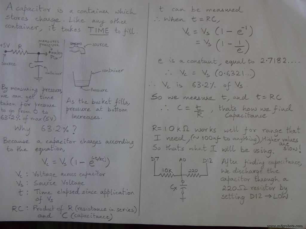
第 3 步:电容计 - 概念

代码
/* RCTiming_capacitance_meter * 代码概念取自 Paul Badger 2008 * * 电容器电压在一个时间常数被定义为充电电压的 63.2%。 * 即,电容器在 1 个时间常数内填充到其总容量的 63.2% */ int analogPin=0; // 测量电容电压的模拟引脚 int chargePin=7; // 给电容充电的引脚 - 连接到充电电阻的一端 int放电Pin=12; //引脚对电容器放电,同样用于二极管测试(chechPin1)浮动电阻值=10000.0; // 我们使用 10kOhm 电阻 unsigned long startTime;无符号长经过时间;浮动微法拉; // 浮点变量以保持精度,使计算浮动 nanoFarads;void setup(){ pinMode(chargePin, OUTPUT); // 设置chargePin 输出digitalWrite(chargePin, LOW); Serial.begin(9600); // 为调试初始化串行传输}void loop(){ digitalWrite(chargePin, HIGH); // 设置chargePin HIGH 和电容器充电startTime =millis(); while(analogRead(analogPin) <648){ // 647 是 1023 的 63.2%,对应满量程电压 } elapsedTime=millis() - startTime; // 将毫秒转换为秒 (10^-3) 并将法拉转换为微法 (10^6),净 10^3 (1000) 微法 =((float)elapsedTime / resistanceValue) * 1000; // (float) 将“无符号长”经过时间转换为浮点数 Serial.print(elapsedTime); // 将值打印到串口 Serial.print(" mS "); // 打印单位 if (microFarads> 1){ Serial.print((long)microFarads); // 将值打印到串口 Serial.println(" microFarads"); // 打印单位 } else { // 如果值小于 1 微法拉,则转换为纳法拉 (10^-9 法拉)。纳法拉 =微法拉 * 1000.0; // 乘以 1000 转换为纳法拉 (10^-9 法拉) Serial.print((long)nanoFarads); // 将值打印到串口 Serial.println("nanoFarads"); // 打印单位 } /* 对电容器放电 */ digitalWrite(chargePin, LOW); // 将充电引脚设置为 LOW pinMode(dischargePin, OUTPUT); //设置放电引脚输出digitalWrite(dischargePin, LOW); // 将放电引脚设置为低电平 while(analogRead(analogPin)> 0){ // 等待电容器完全放电 } pinMode(dischargePin, INPUT); // 将放电引脚设置回输入}
第 4 步:二极管测试
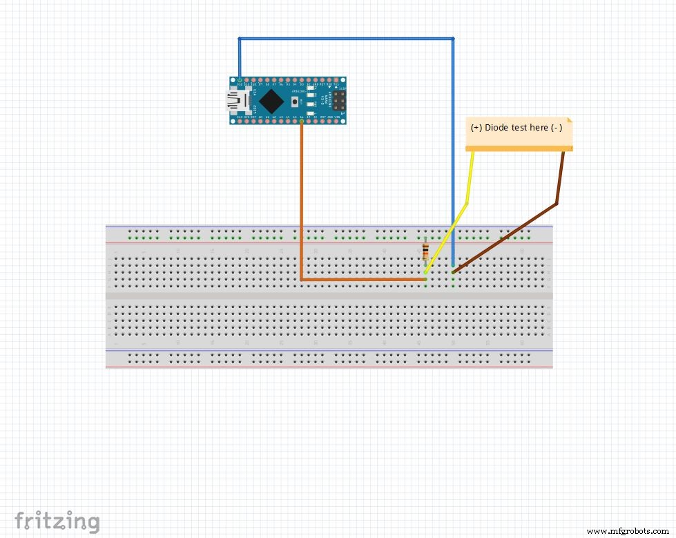
使用 10k 欧姆电阻将模拟引脚上拉至 5V。所以模拟引脚读取 1023 当没有任何连接时。 D12 设置为 OUTPUT , 低 .
当二极管在模拟引脚之间正向偏置时 (5V ) 和 D12 (地 ), 模拟引脚 读取 100-400 .
当它被反向偏置时,实际上有一个非常小的电流流过模拟引脚 读取 900-1023 .
这样我们就可以简单地找出任何二极管的 p 和 n 侧。这可用于快速检查 LED 和二极管。
代码
String state ="null";int checkPin1 =12;int checkPin2 =6;void setup() { Serial.begin(9600);}void loop() {pinMode(checkPin1, OUTPUT);数字写入(checkPin1,低); //引脚11设置为低//模拟读取通常由10k电阻上拉,因此空读数为1023//在正向偏置中,模拟引脚连接到checkPin1,即低电平。所以读数小于1023//实际上也有小电流在反向偏置中流动,所以我们取700来区分 if(analogRead(checkPin2)<700){ state="forward"; Serial.println(状态); Serial.println(analogRead(checkPin2));状态=“空”;延迟(500);}
第 5 步:实时时钟 (RTC)
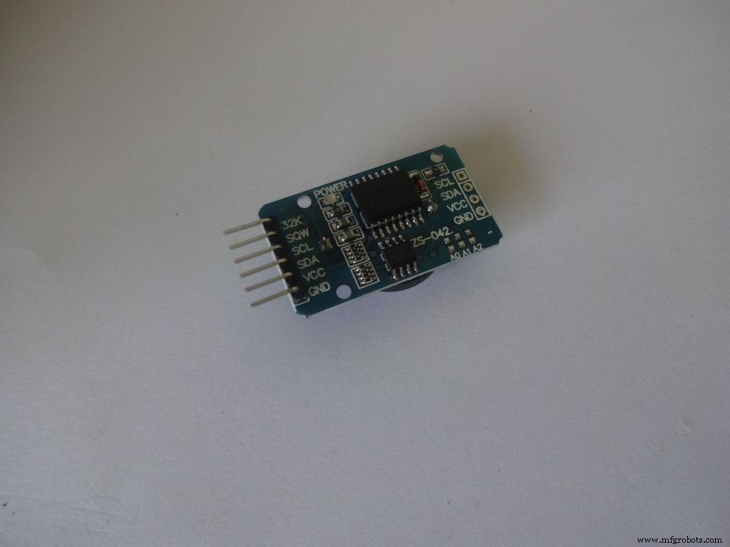
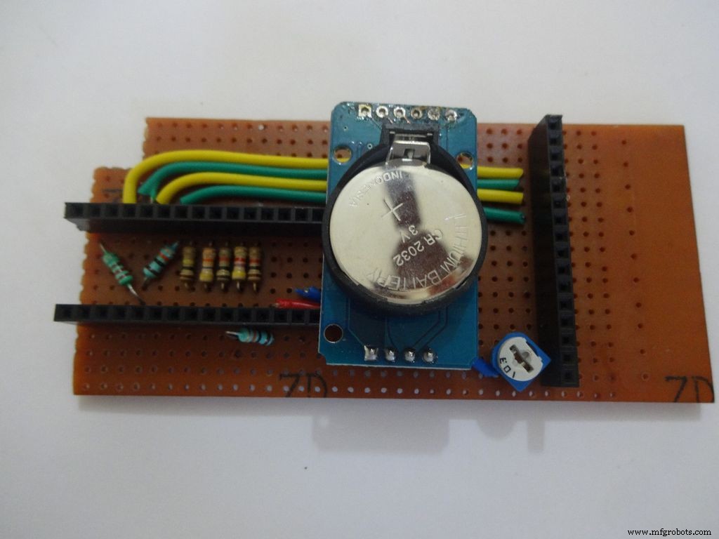
RTC 维护秒、分、小时、日、日期、月和年信息。由于内部装有小型纽扣电池,即使外部电源断开,它仍会继续计数。对于少于31天的月份,月末日期会自动调整,包括闰年的更正。
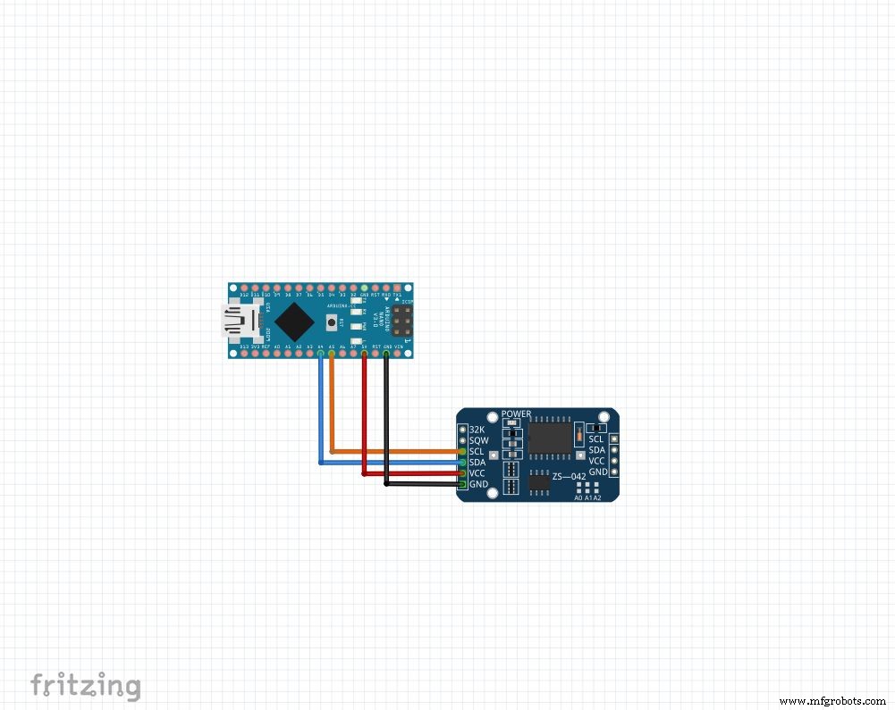
无论您拥有什么模块,我们都将使用 4 个引脚:Vcc , 地 , SDA 和 SCL . SDA 和SCL arduino nano 和 uno 上的引脚是 A4 和A5 分别。对于其他 arduino,请使用谷歌搜索!
我们将使用“RTClib”库,它使设置和访问时间变得超级简单!该库可以在此处下载(单击“下载 ZIP”,然后将“RTClib-master”解压缩到您的 Arduino 库文件夹中。有关安装库的更多信息。)
要设置时间,请下载此步骤附带的“RTC_set_time.ino”并取消注释行,
rtc.adjust(DateTime(F(__DATE__), F(__TIME__)));
如果要在编译时使用计算机上设置的时间。或者
rtc.adjust(DateTime(2014, 1, 21, 3, 0, 0)); //年、月、日、时、分、秒
设置自定义时间。
如图所示连接并上传。打开系列 以 9600 波特监控 查看当前时间。几个小时后再次检查,看看 RTC 是如何赶上来的。
确保您推荐这些行并在设置一次时间后再次上传。否则每次 Arduino 重置时您都会不断重置它!
代码
//日期和时间函数使用通过I2C和Wire连接的DS1307 RTC lib#include #include RTC_DS1307 rtc;//创建RTC_DS1307的“rtc”对象,对象用于访问函数//更多关于对象和类:https://www.youtube.com/watch?v=ABRP_5RYhqUchar daysOfTheWeek[7][12] ={"Sunday", "Monday", "Tuesday", "星期三”,“星期四”,“星期五”,“星期六”};无效设置(){ Serial.begin(9600); rtc.begin(); // 以下行将 RTC 设置为编译此草图的日期和时间 // rtc.adjust(DateTime(F(__DATE__), F(__TIME__))); // 此行使用明确的日期和时间设置 RTC,例如设置 // 2014 年 1 月 21 日凌晨 3 点,您将调用: // rtc.adjust(DateTime(2014, 1, 21, 3, 0, 0) );}void loop() { DateTime now =rtc.now(); Serial.print(now.year()); Serial.print('/'); Serial.print(now.month()); Serial.print('/'); Serial.print(now.day()); Serial.print(" ("); Serial.print(daysOfTheWeek[now.dayOfTheWeek()]); Serial.print(") "); Serial.print(now.hour()); Serial.print(':'); Serial.print(now.minute()); Serial.print(':'); Serial.print(now.second()); Serial.println(); Serial.println();延迟(1000);}
第 6 步:最终设置
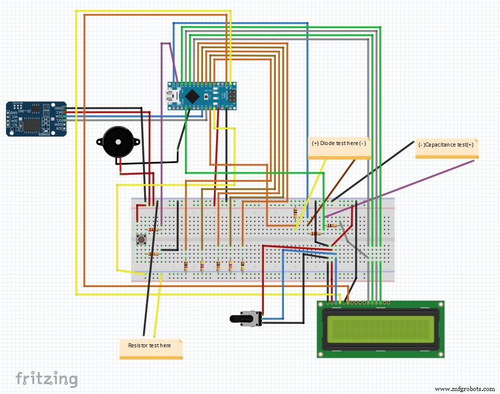
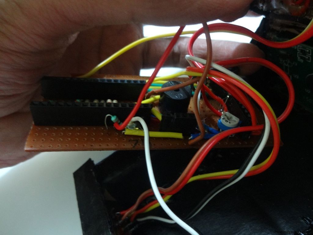
所以这就是组合所有元素后的最终电路。最后附上主要代码和fritzing文件。
如果您还没有从 fritzing.org 下载 fritzing。
解压 Main_code.rar 文件并打开 Main_file_rtc.ino。我已将所有变量声明包含在单独的 definations.h 中 头文件,打开主代码时会自动添加。
不同的部分组成函数: Clock() , findResistance() , findCapcitance() 和 diodeTest() .它们写在单独的选项卡中,使阅读变得容易,更改也易于实施。主文件只是检查“模式按钮”的状态并调用相应的函数。
其他细节在代码本身中有适当的解释。
在面包板上试运行后,我们准备开始制作 IC!
注意:蜂鸣器如果尚未使用,可在必要时使用,例如连续功能。
第 7 步:准备开关
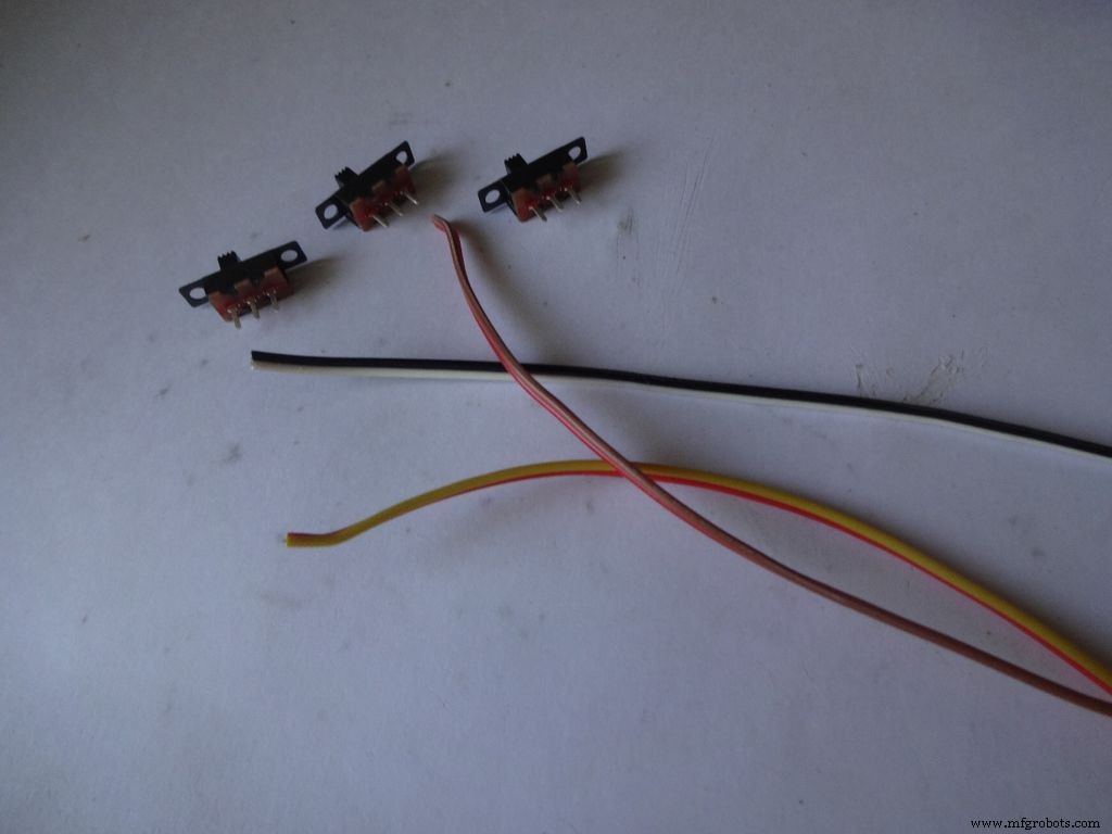
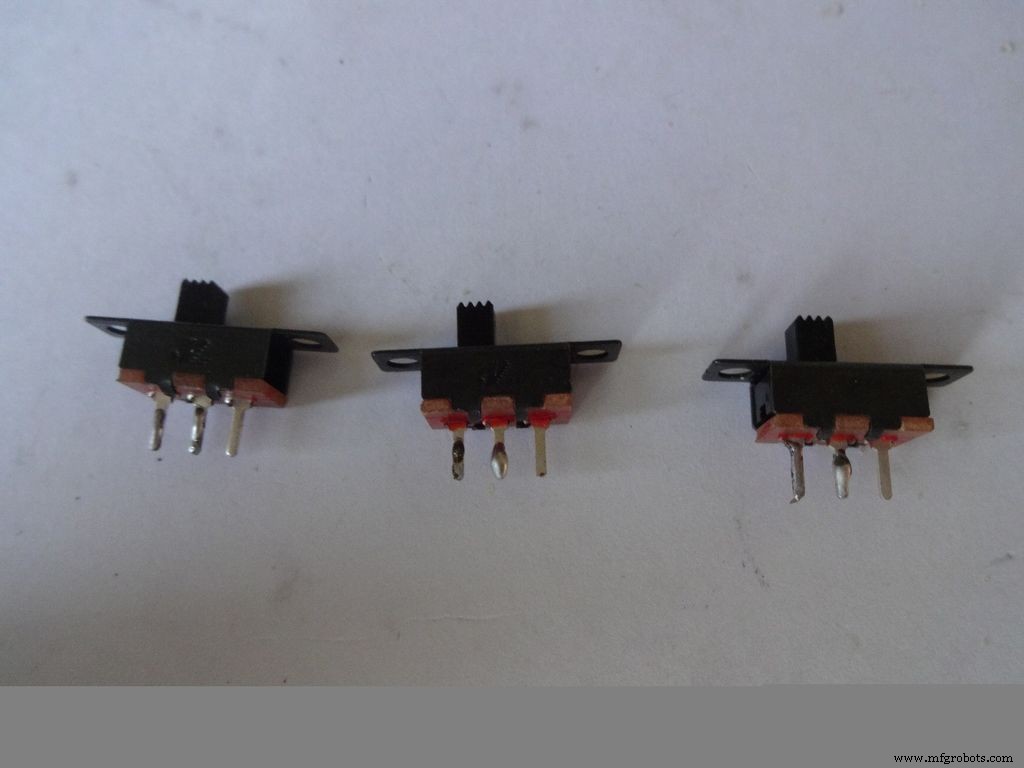


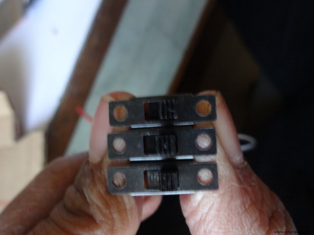
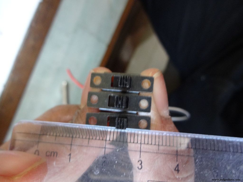
取3个滑动开关和3对长约10厘米的电线。我为此分开了带状电缆。
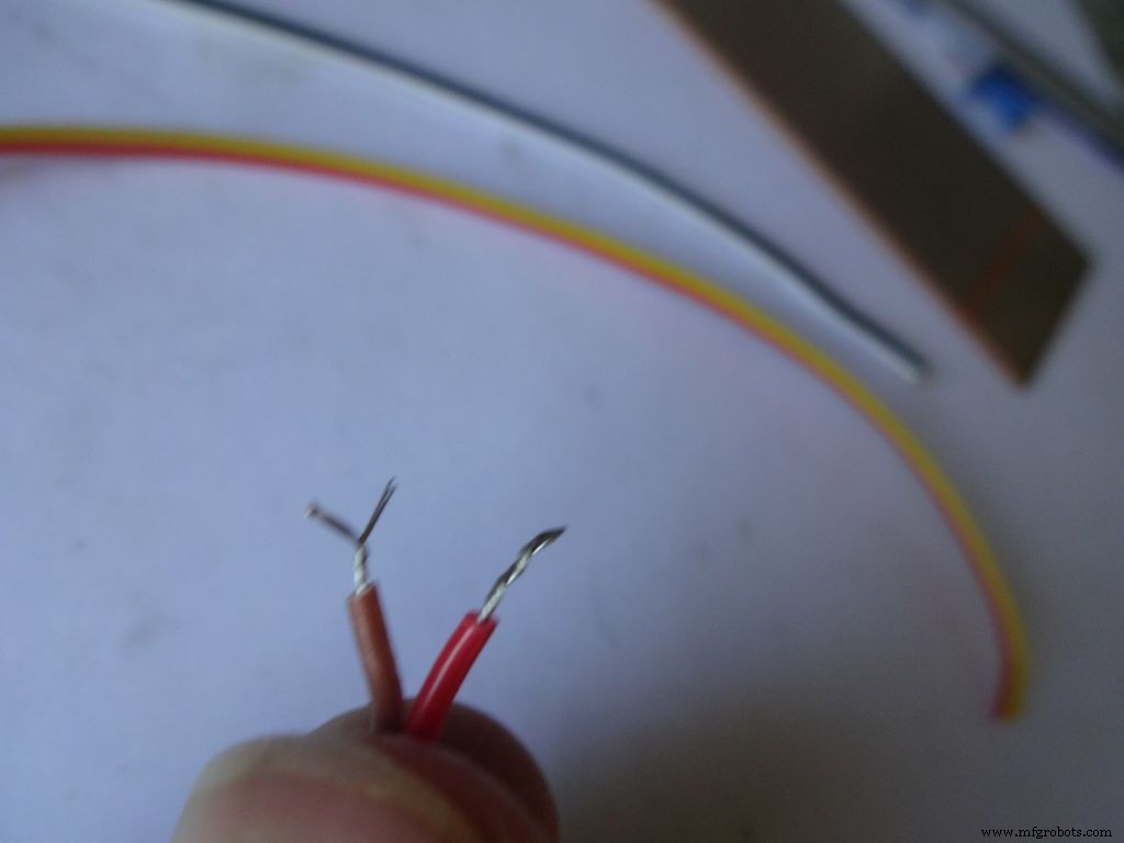
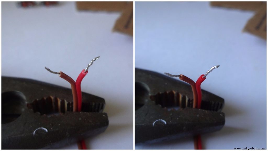
剥去一小部分绝缘层(不超过 5 毫米)并扭绞股线。
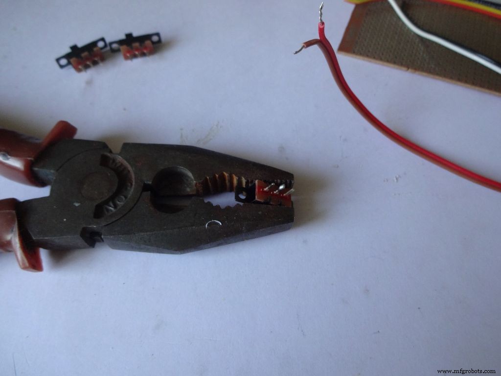
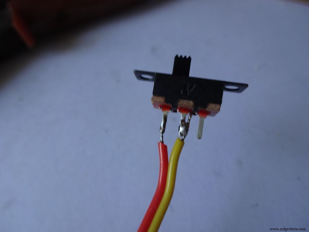
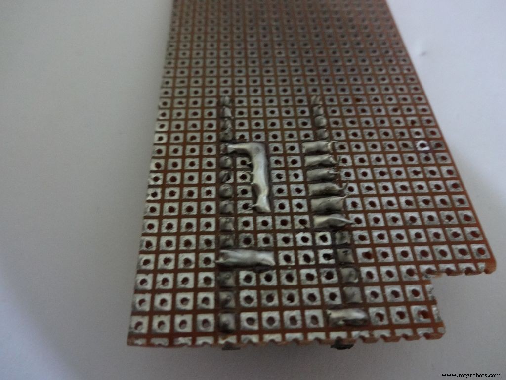
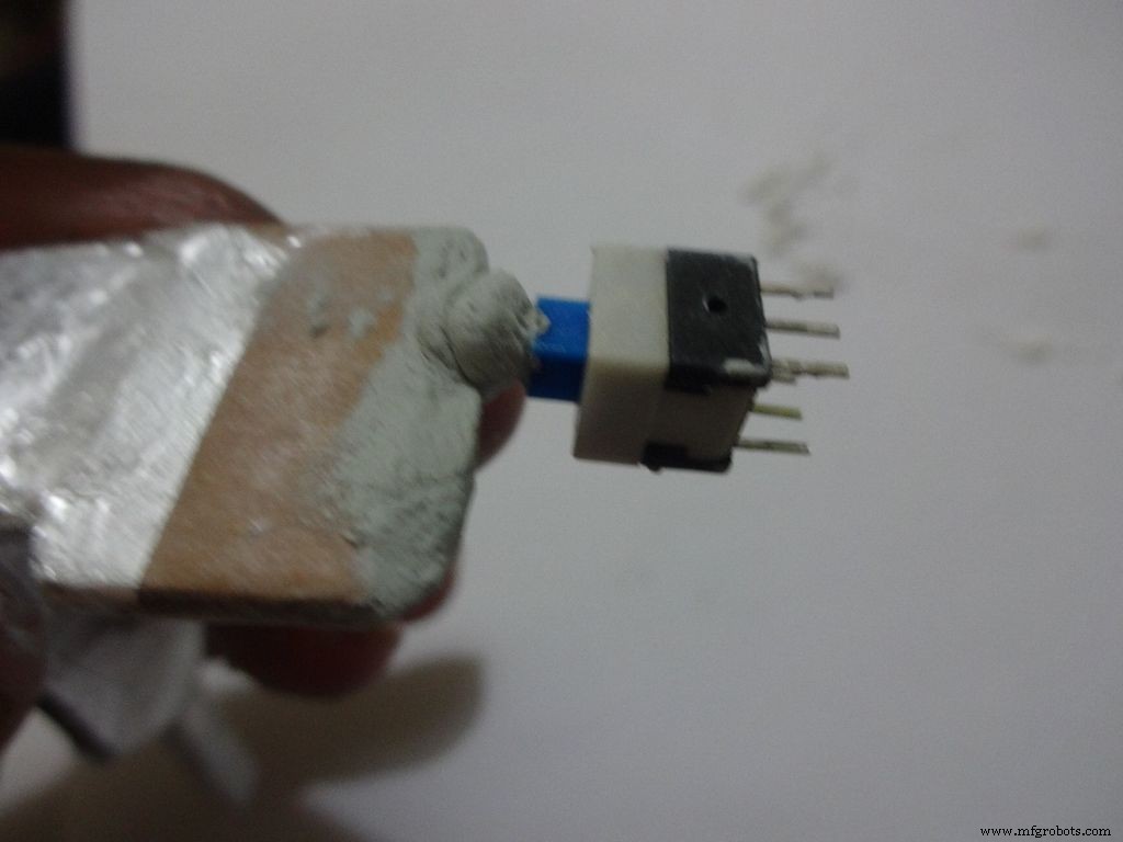
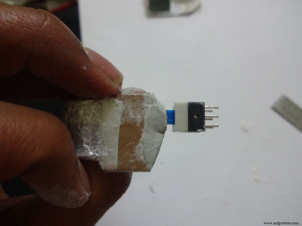
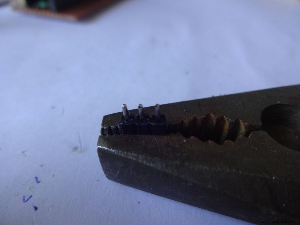
在每个开关的 2 个相邻引脚上涂抹一些焊料。焊接时用一些东西把它固定到位,我用了一把重钳子。
如果您以前没有焊接过,现在是开始的好时机。 Youtube 上有大量关于教你如何正确焊接的视频。 PACE 的课程内容非常丰富,请观看。
接下来我们必须给电线“镀锡”。将烙铁的尖端接触到要镀锡的电线。在尖端和电线之间涂上一点焊料,这会形成一个桥,将热量从尖端传导到电线。然后您将焊料直接涂在焊锡烙铁头的另一侧 .去除焊料。取下尖端。关于这个的视频。
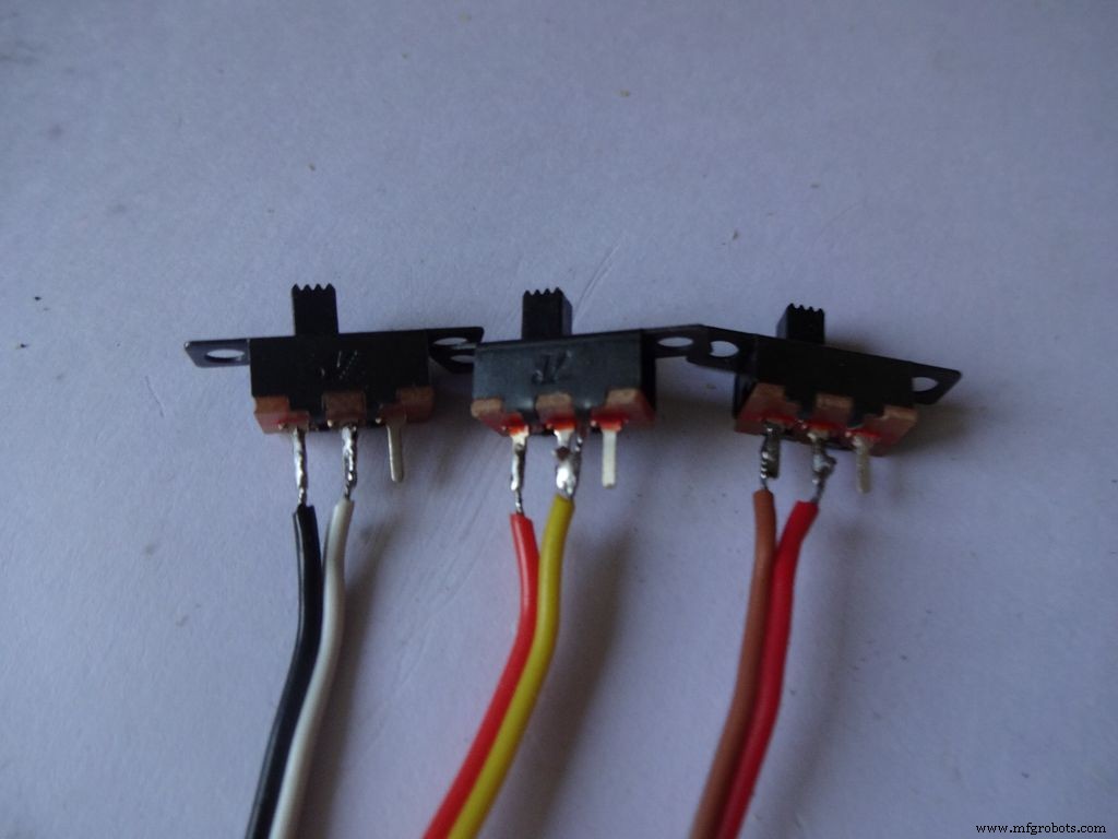
之后,将开关固定到位,将其中一根镀锡线连接到引脚并通过接触烙铁回流焊料。对第二根电线做同样的事情。请注意,我将深色电线放在开关的一侧。
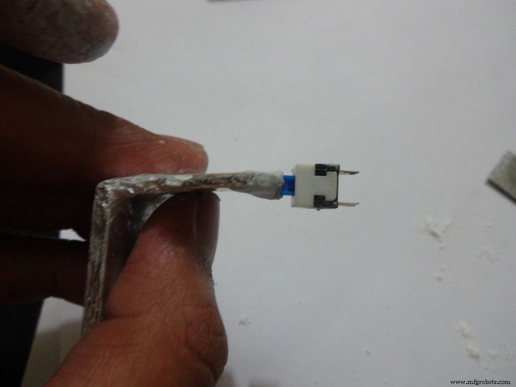
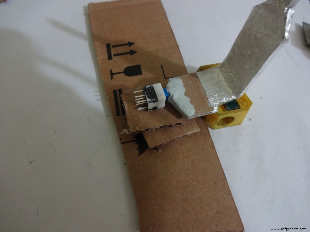
现在重复该过程并将两根电线连接到按钮(这将是重置按钮)。 确保不要将电线连接到按钮的正常连接端。
第 8 步:制作案例 - 切割布局
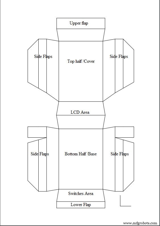
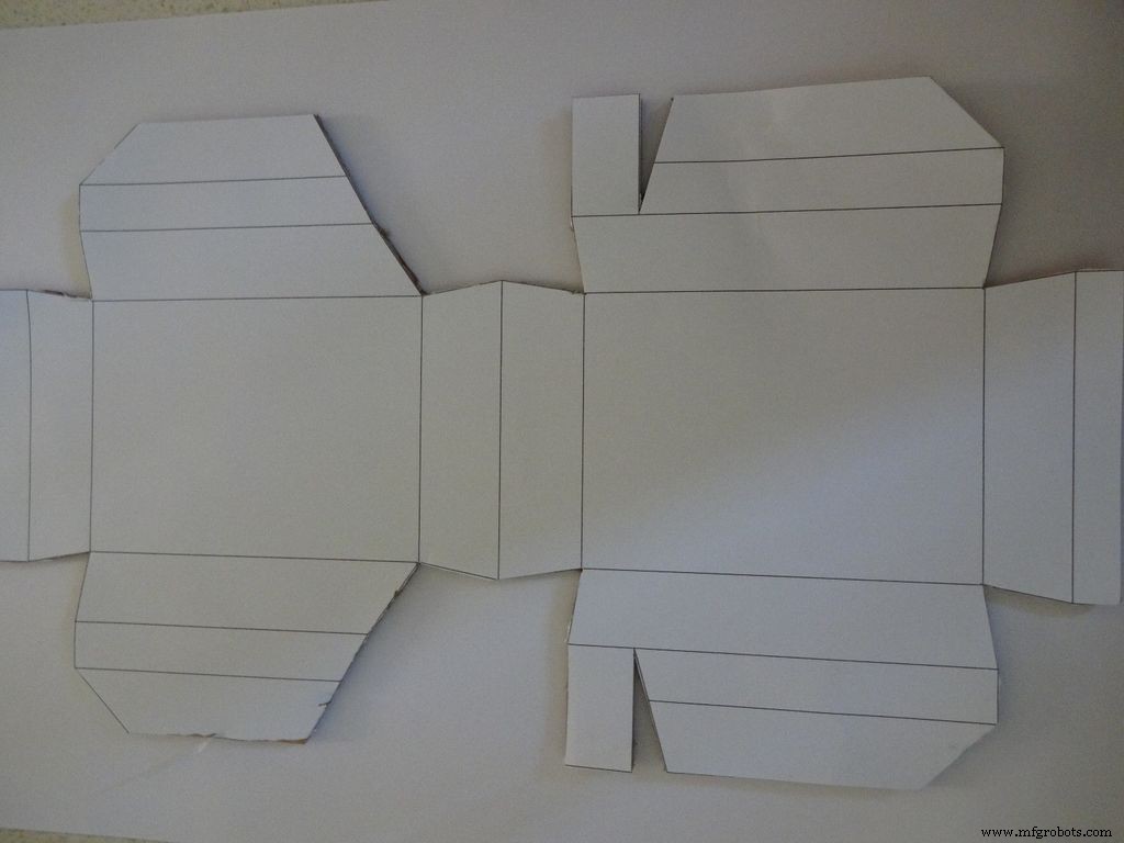
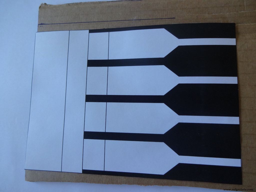
下载“Layout_Final_A3.pdf”或“Layout_Final_ANSI_B.pdf”,根据您所在地区可用的纸张尺寸。附在最后。
将其打印在 A3 尺寸的纸张(29.7 x 42.0 厘米或 11.69 x 16.53 英寸)或美国替代的 ANSI B(11 x 17 英寸或 279 × 432 毫米)上。 确保在打印时选择正确的纸张尺寸、方向,并选择“实际尺寸”选项。 通过测量右下角的小直角来确认打印是准确的,应该是 2cm x 2cm。
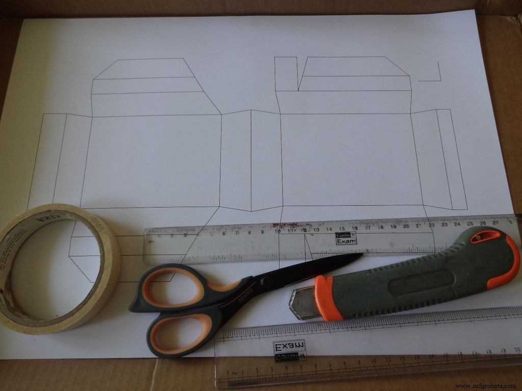
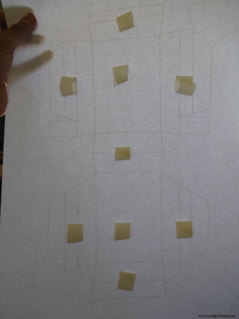
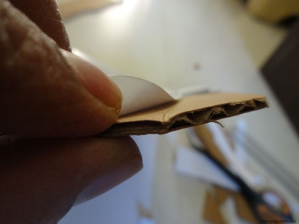
切一块纸板大约比布局多。撕下一小块胶带,形成一个“双面粘性”卷,然后将其粘贴在所示位置。然后将纸张贴在纸板上。
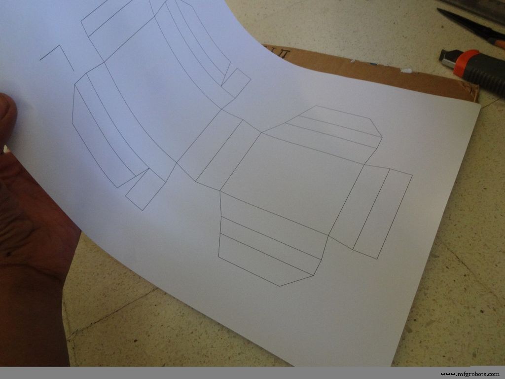
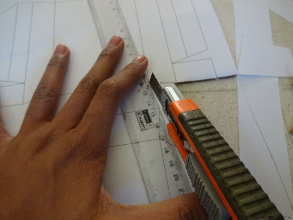
使用锋利的剪刀或带直尺的美工刀切割案例布局的外边界。我发现美工刀比剪刀好得多。大多数刀具都有可以分阶段折断的刀片,以获得新鲜而锋利的刀尖,因此建议这样做。在您正在切割的部分下方再放一块纸板或木头,这有助于获得更干净的切割。
此外,切割时没有将标尺正确保持在线是一个常见的错误。不要着急这样做。
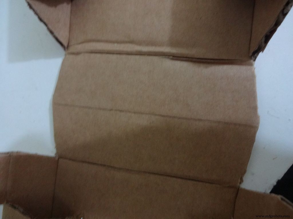
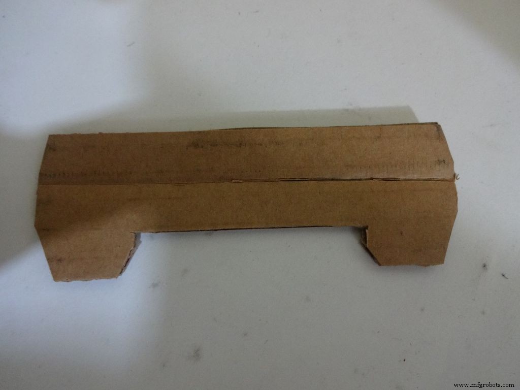
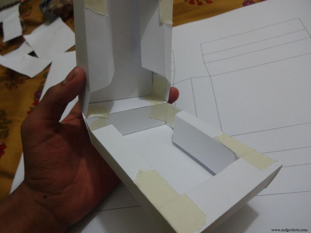
第 9 步:制作表壳 - 压痕和折叠
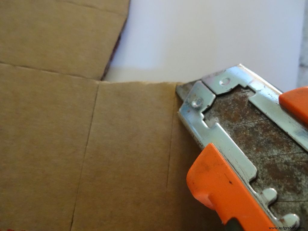
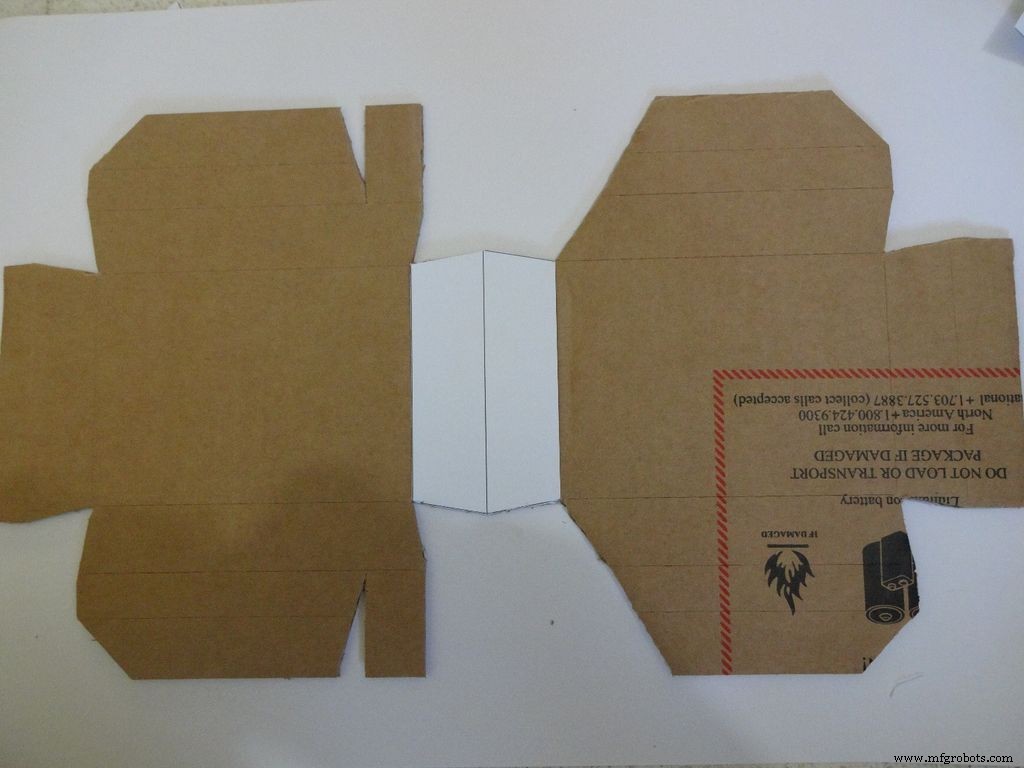
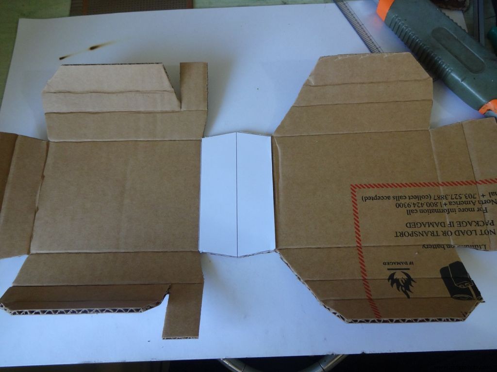


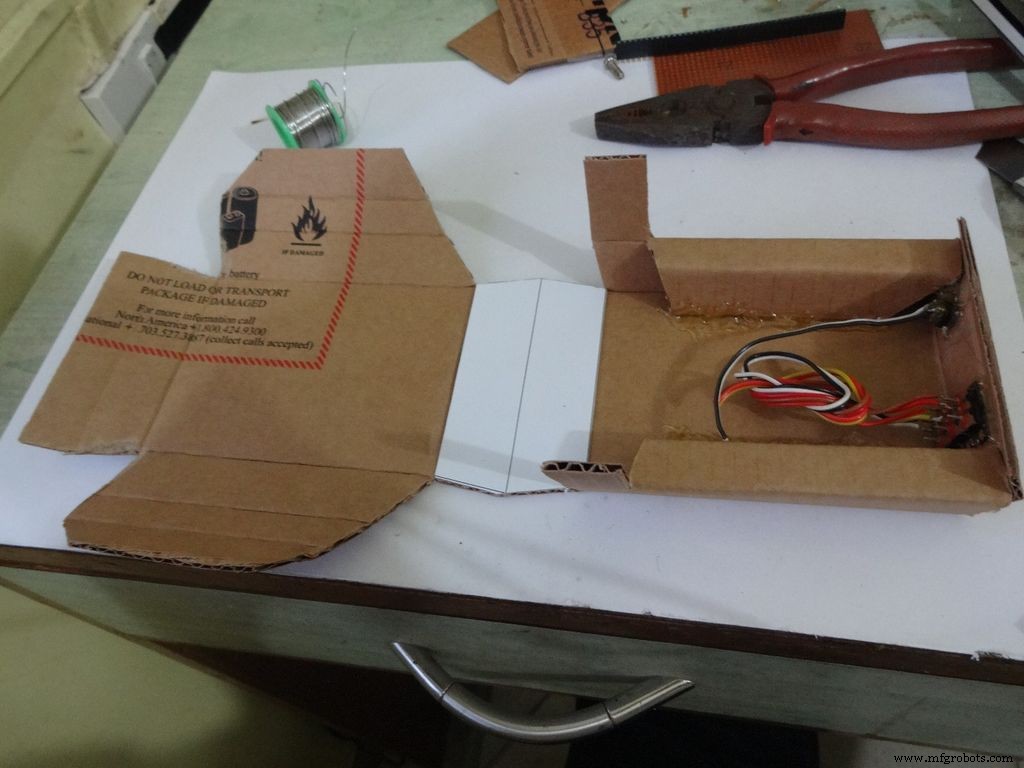
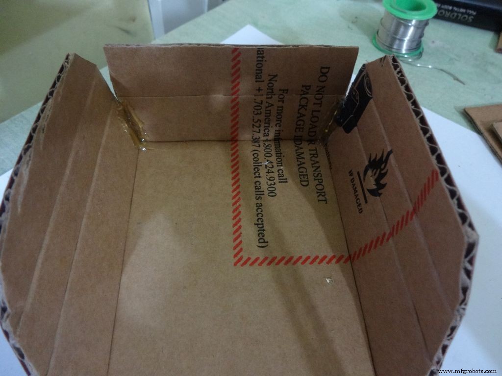
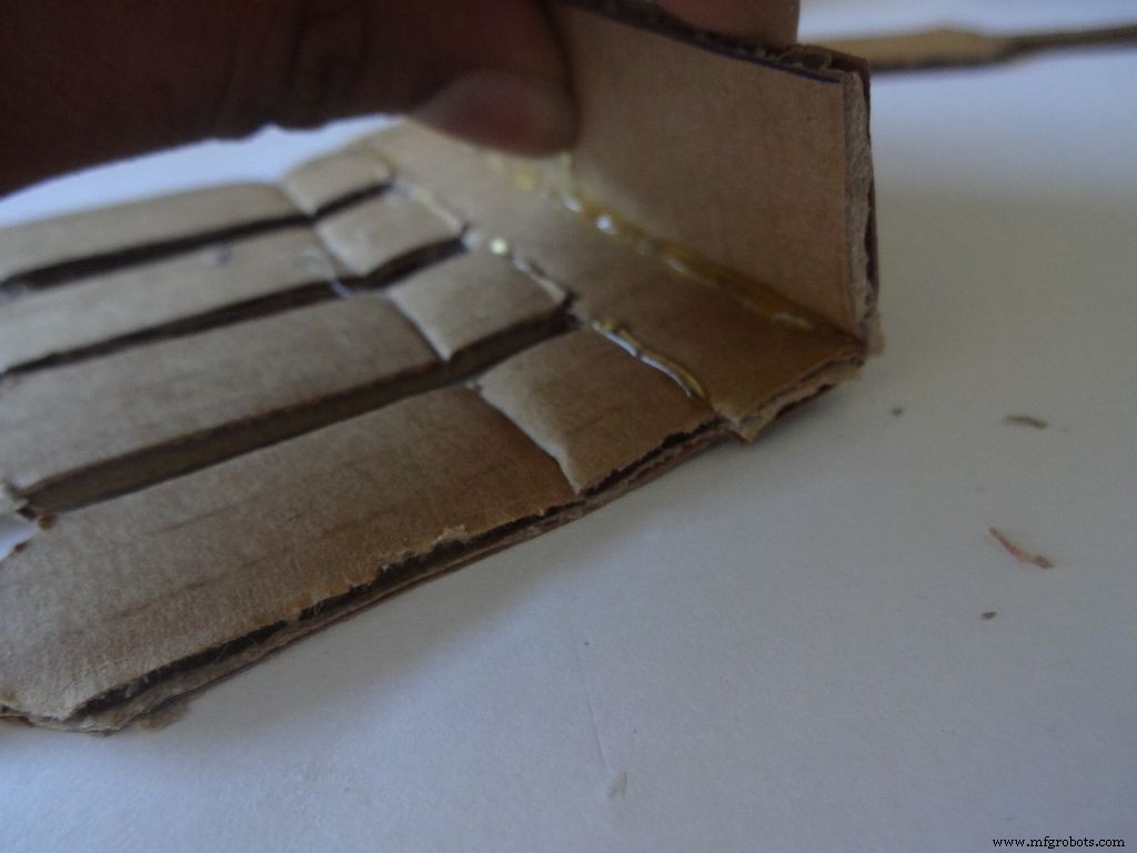
使用带有刻度的裁纸器,沿着所有折叠线小心地折痕,LCD 区域中的中间线除外。 弯曲和折叠所有可折叠部分并纠正任何不完整的折痕。
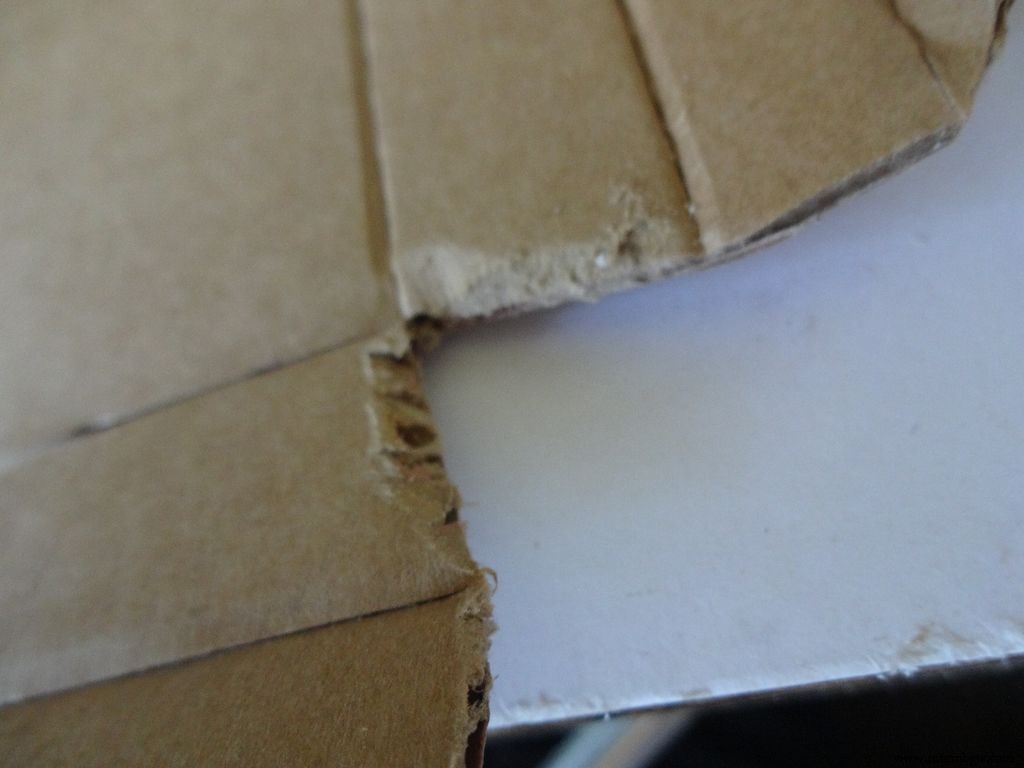
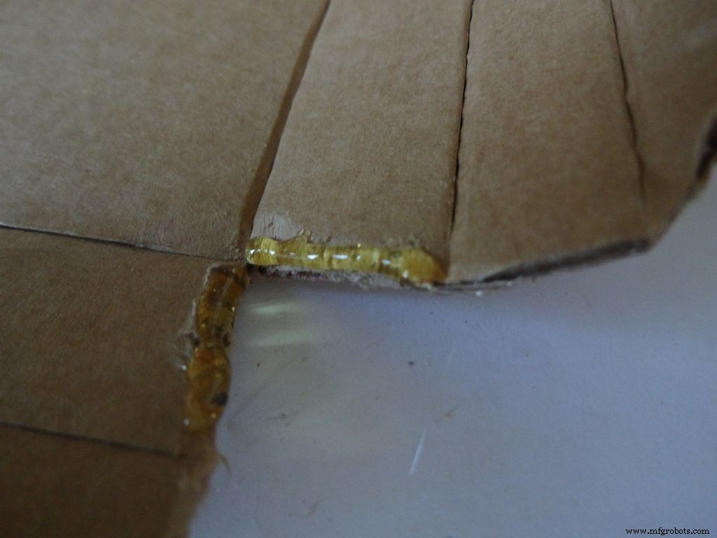
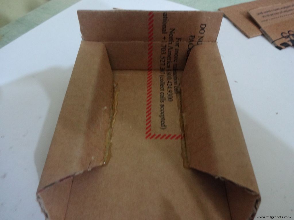
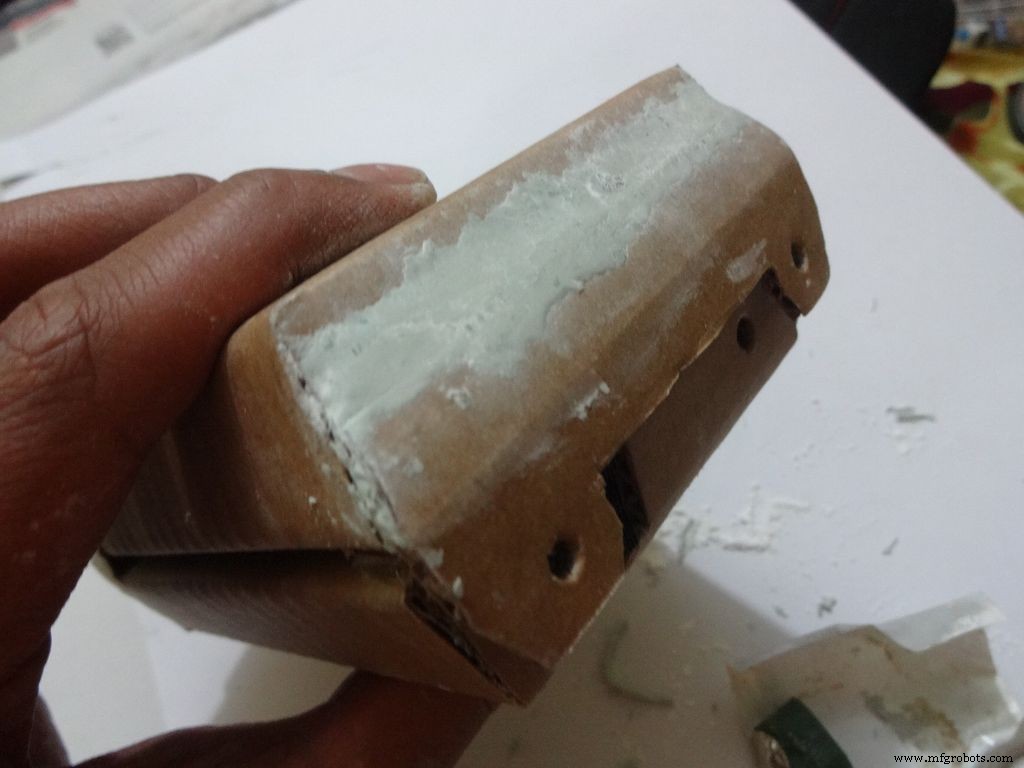
对于下半部分或底部:
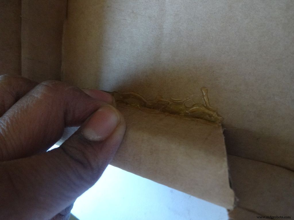
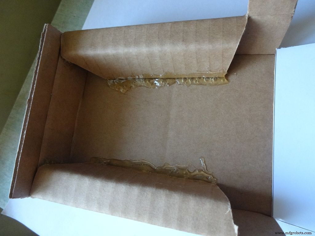
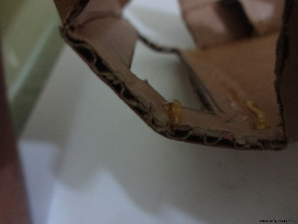
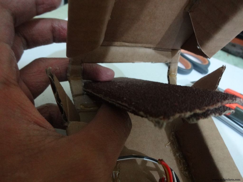
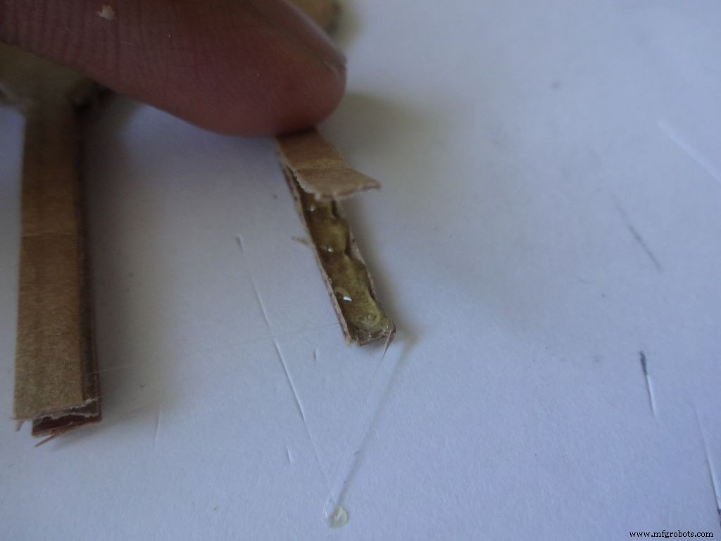
用砂纸将前四个边缘倾斜打磨,用胶枪(一次一面)涂上热胶,待胶水冷却后加入并保持30-60秒。
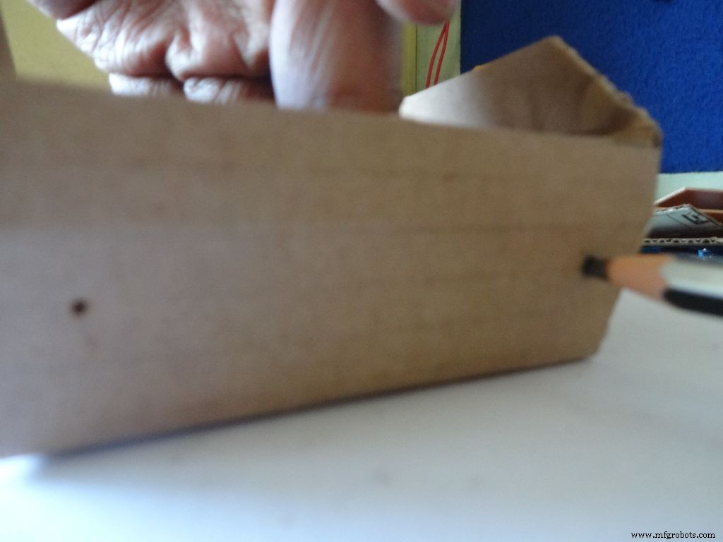
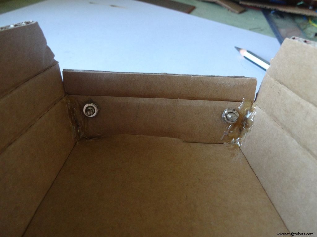
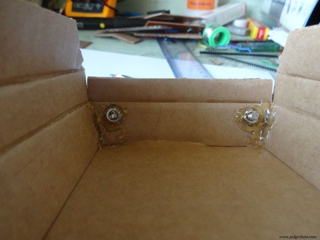
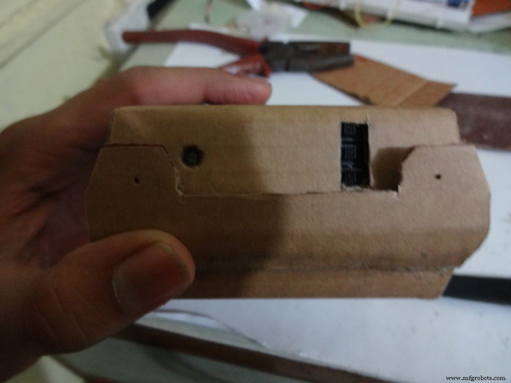
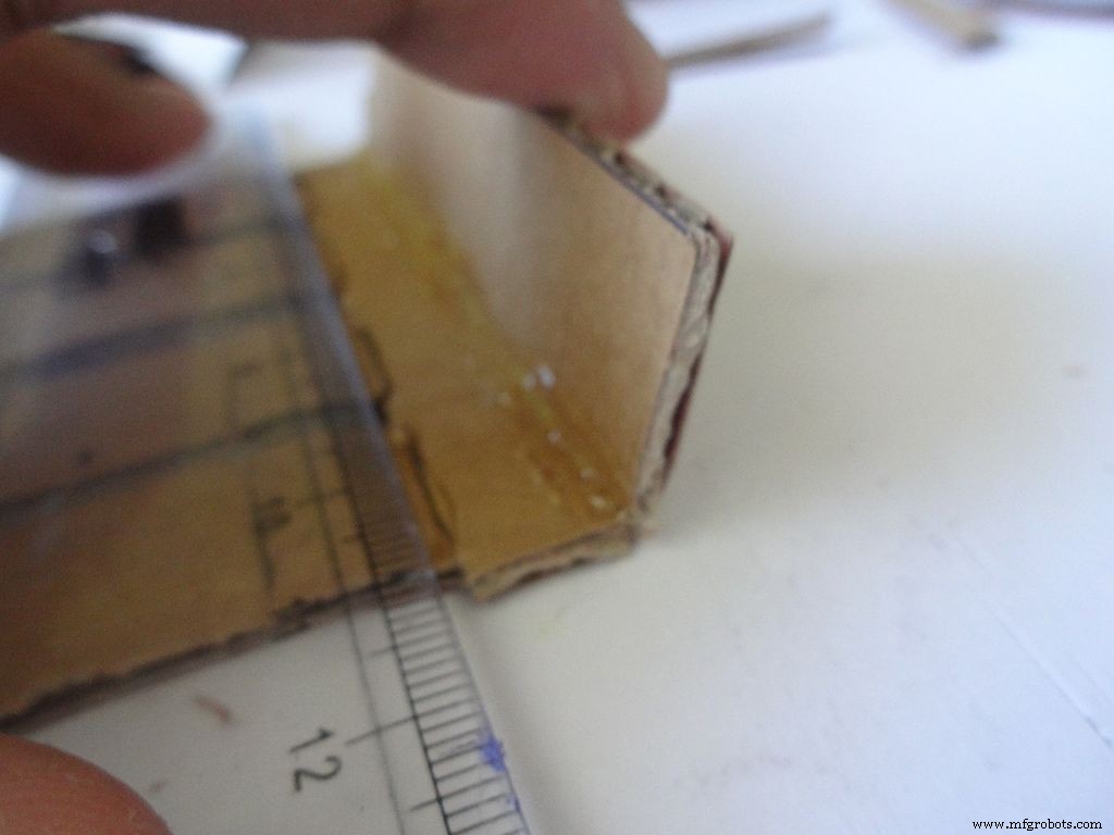
如图所示,用拇指钉开两个孔,然后用铅笔将其放大以适合螺栓。拧紧内侧的螺母,涂上热胶(就在螺母上!),让它冷却。用螺丝刀拆下螺栓。
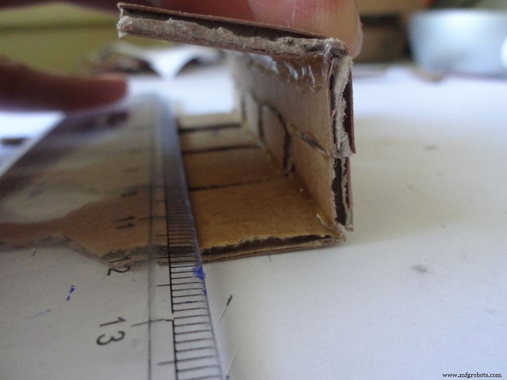
接下来,将两个侧翼向内折叠并粘贴。襟翼外侧应略倾斜,中间部分平坦。
第 10 步:制作案例 - 添加开关
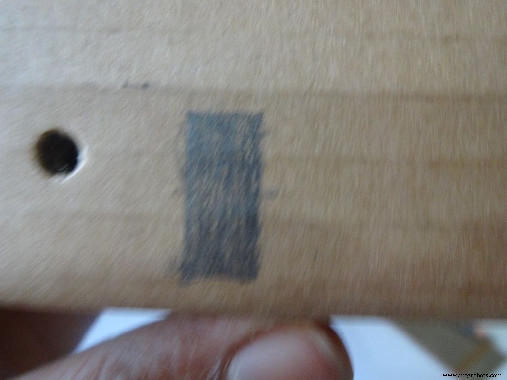
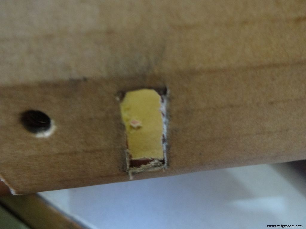
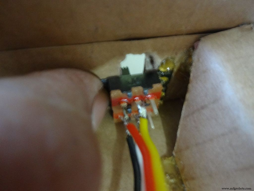
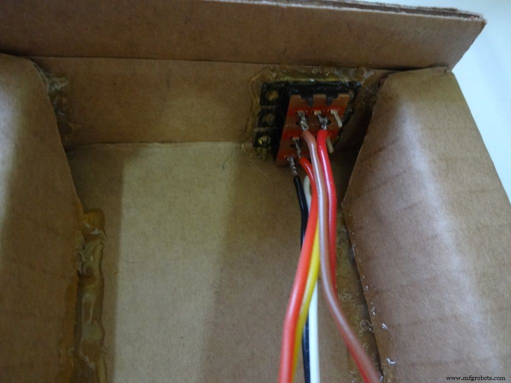
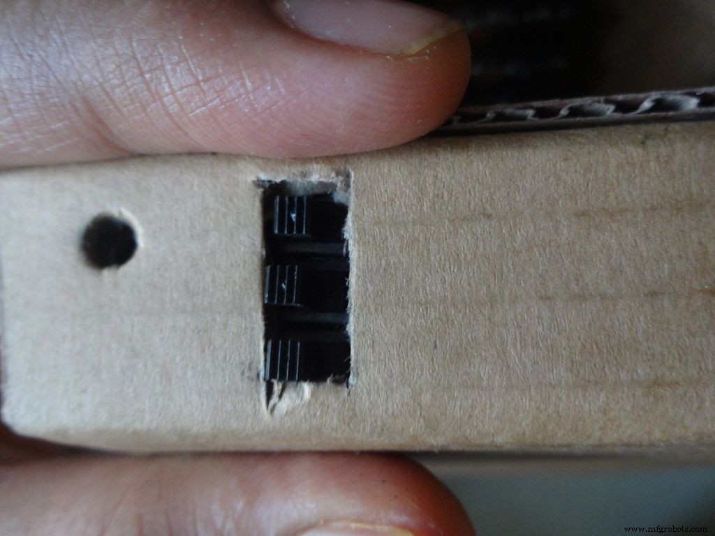
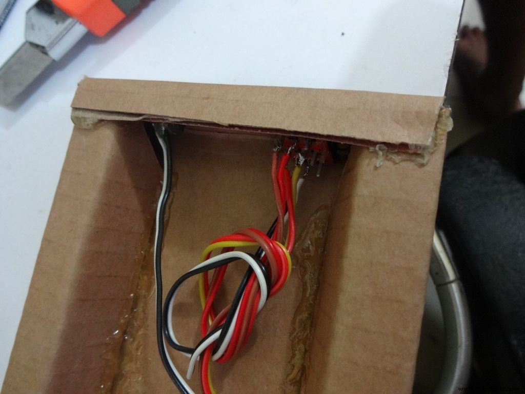
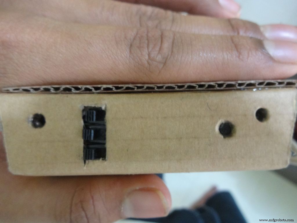

拿我们之前焊接的 3 个带电线的滑动开关,测量所需矩形的大致尺寸。将其标记在框的左侧(从外侧向左)。用刀具切割,在里面稍微打磨一下以去除任何伸出的材料。
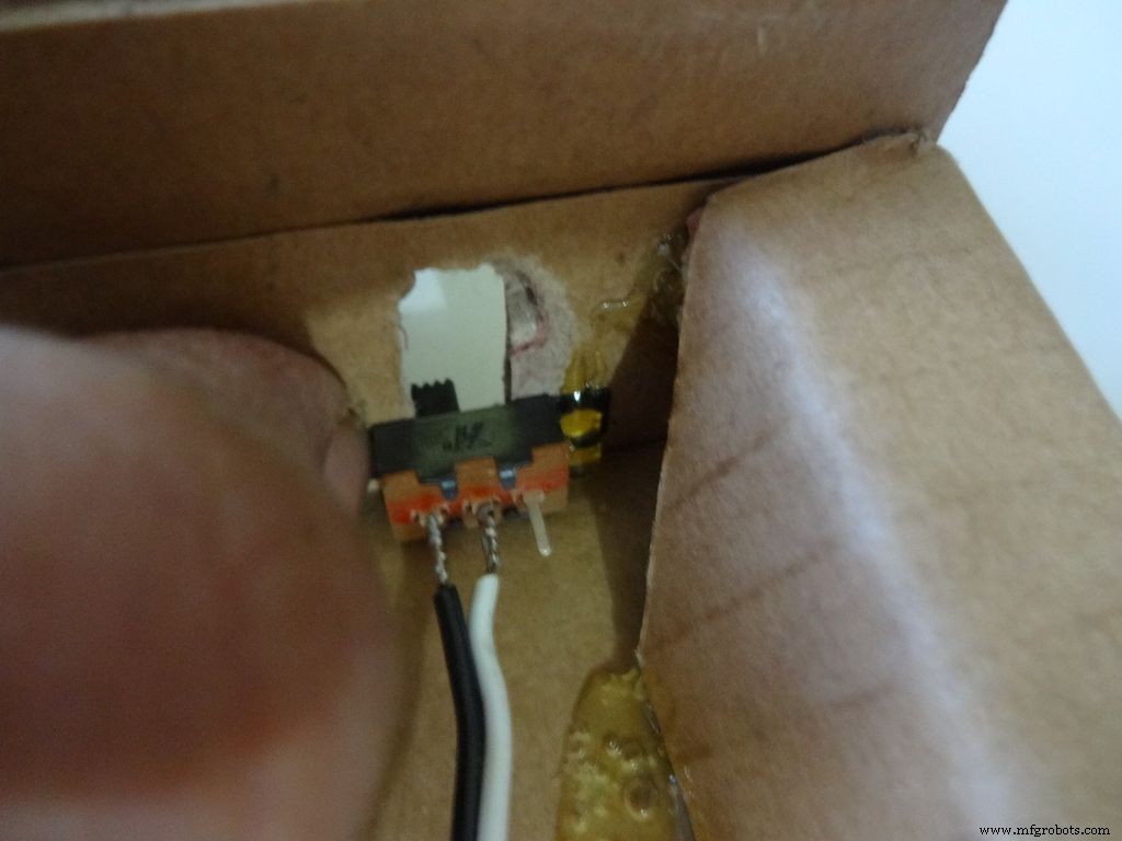
将第一个开关保持在适当的位置,并在握住它的同时在一侧添加胶水。使它冷却。对另外两个也重复,然后在剩余的边上添加胶水。注意:开关的接线针脚应在同一侧。
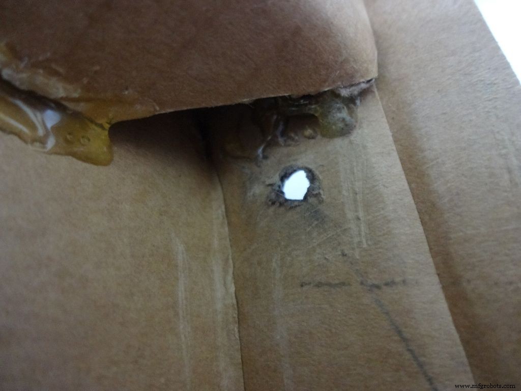
Make another hole on the other side for the reset pushbutton. Hold the button in place and add glue. Fold the lower flap inwards and stick it.
Step 11:Making the case - Top half or cover
Sand the edges and stick the side flaps inwards(just like the base) for the top half
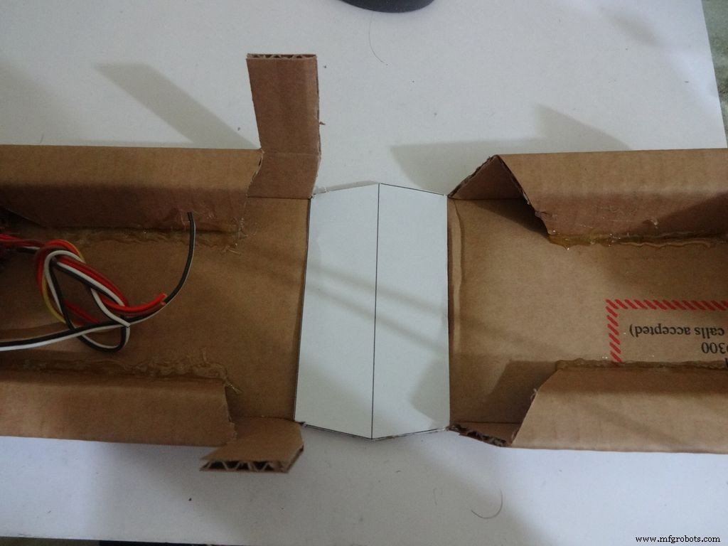
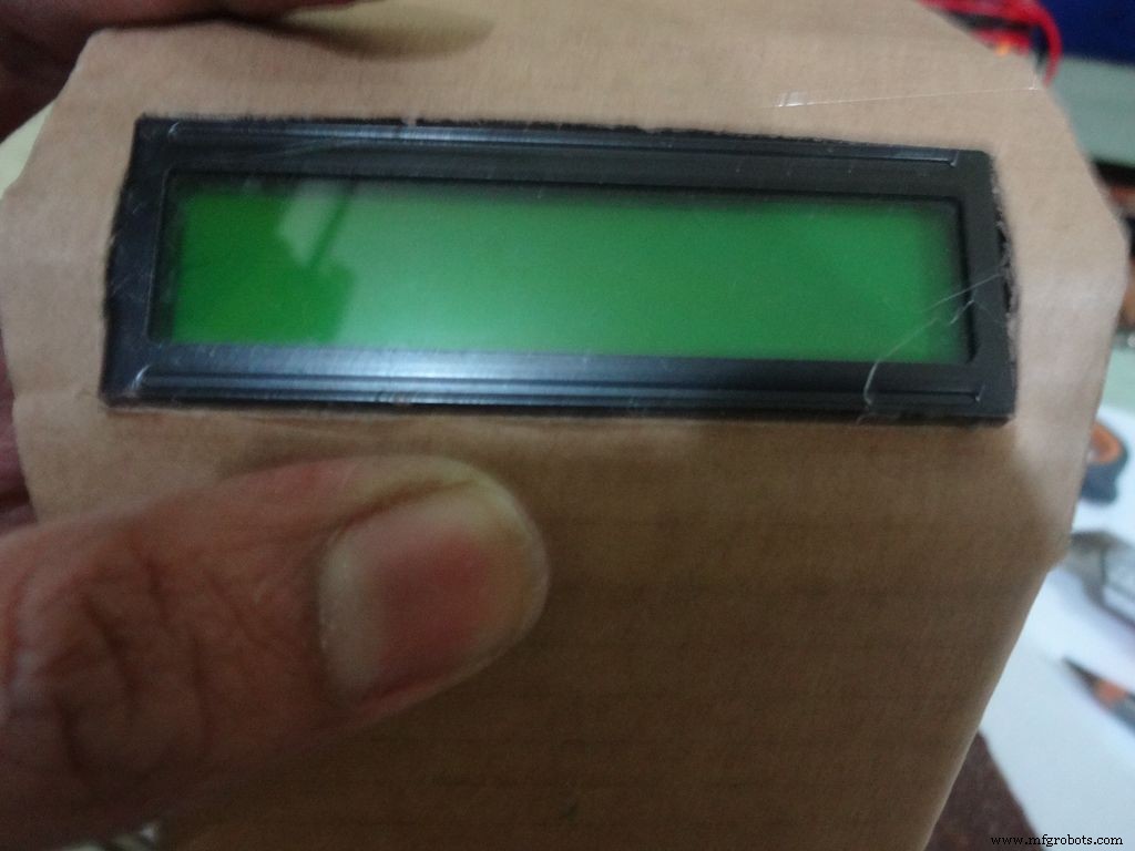
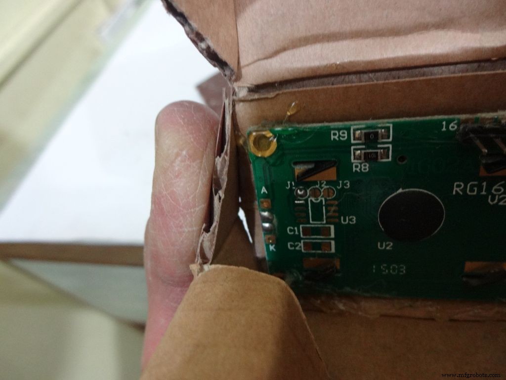
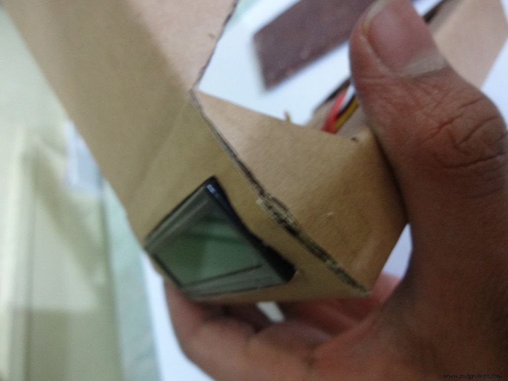
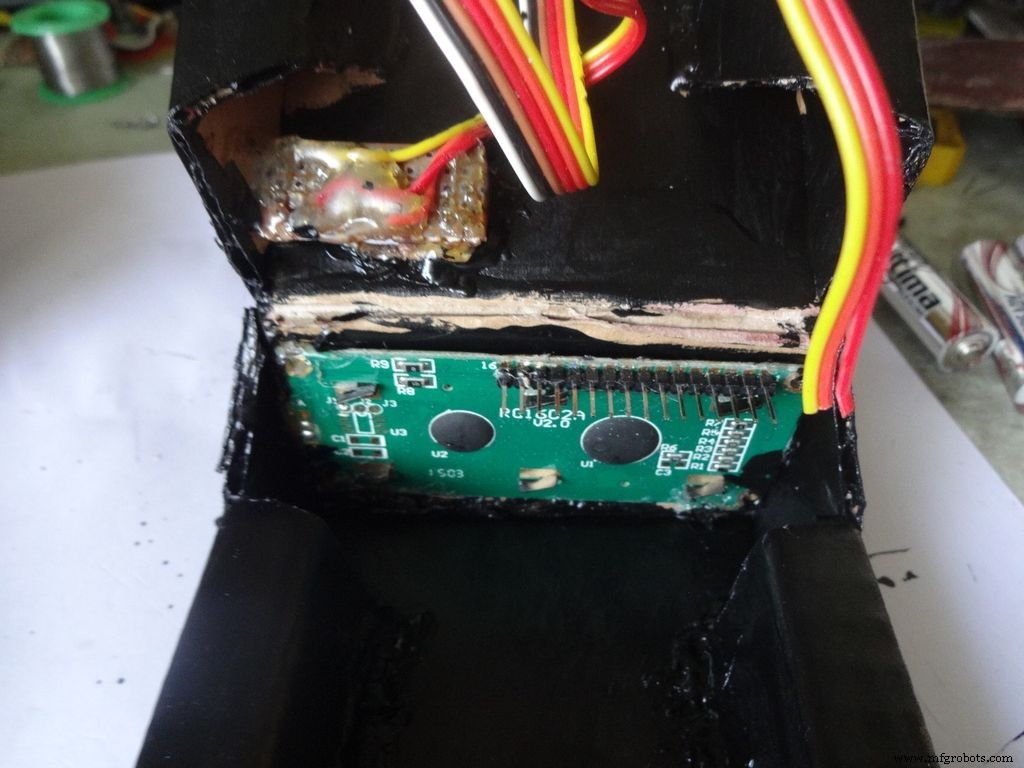
Step 12:Making the case - Adding the LCD
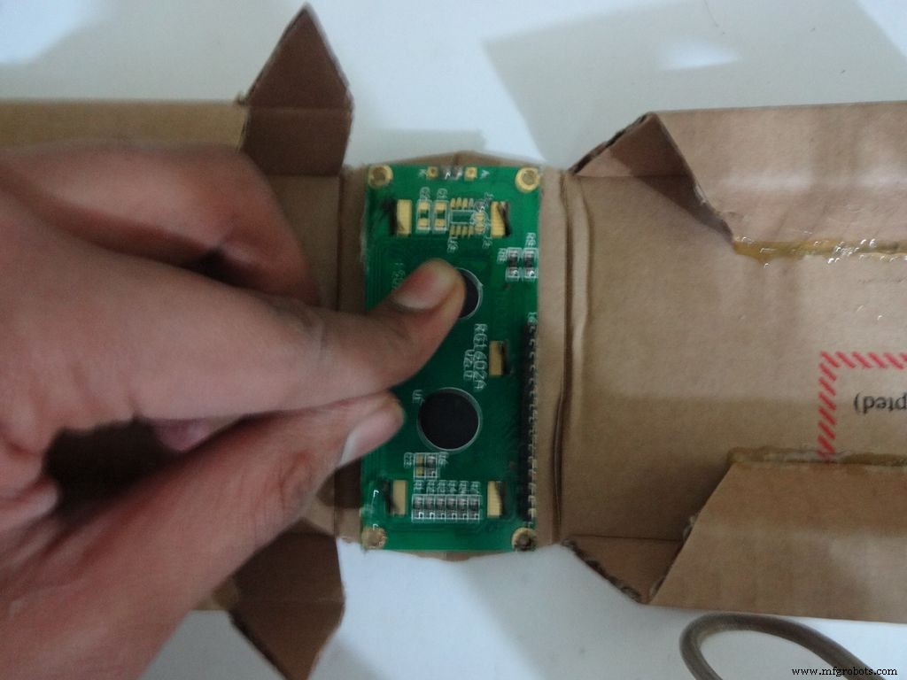
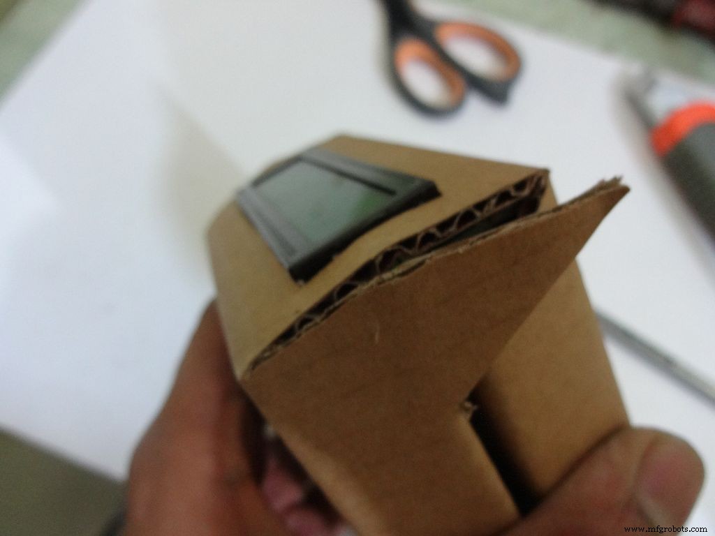
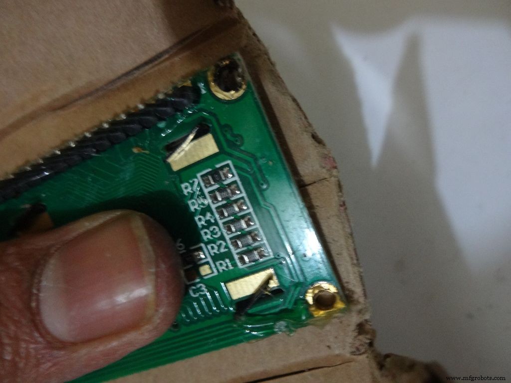
Crease the middle line. (Didn't do it earlier as it is delicate and gets loose soon).
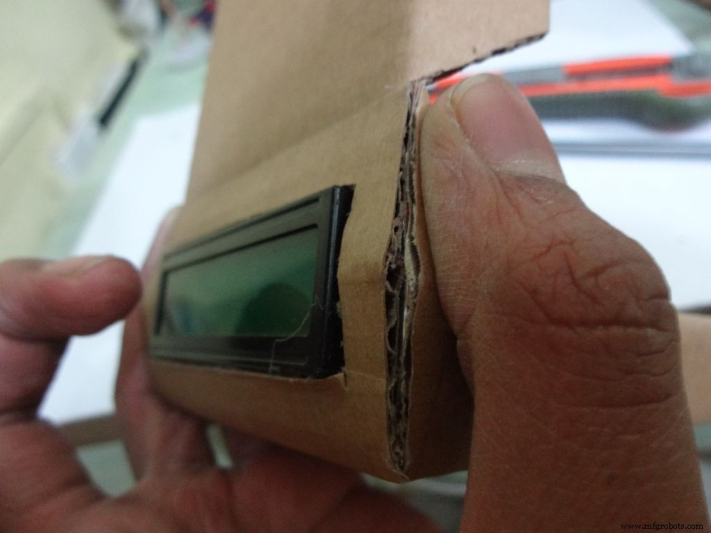
Fold the cover over to the base and check whether everything looks alright, sufficient spacing should be left for the IC pins. (See photo)
Cut the covering flaps as shown in the images.
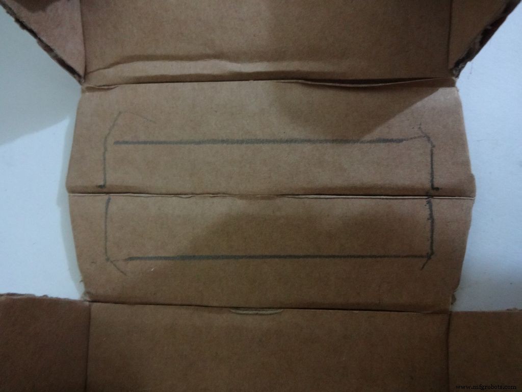
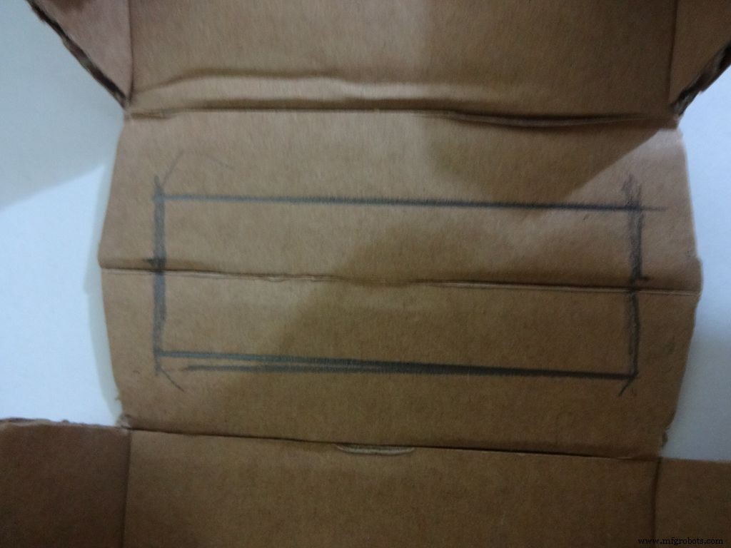
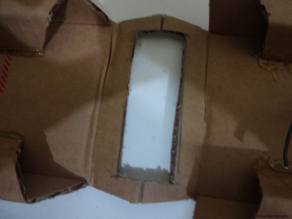
Keep the LCD at the center of the LCD Area, mark it with a pencil. Using a ruler, make the rectangle properly and cut it carefully using a cutter. Fold the LCD window and apply glue to the hinges to keep them at their correct position. Insert the LCD and make any modifications if required.
Finally, apply glue to the four corners(don't put excess) of the LCD and place it in position.
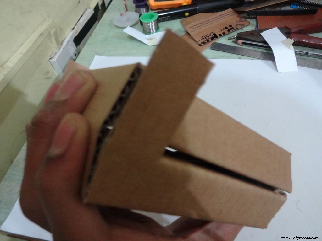
Step 13:Making the case - Final flaps
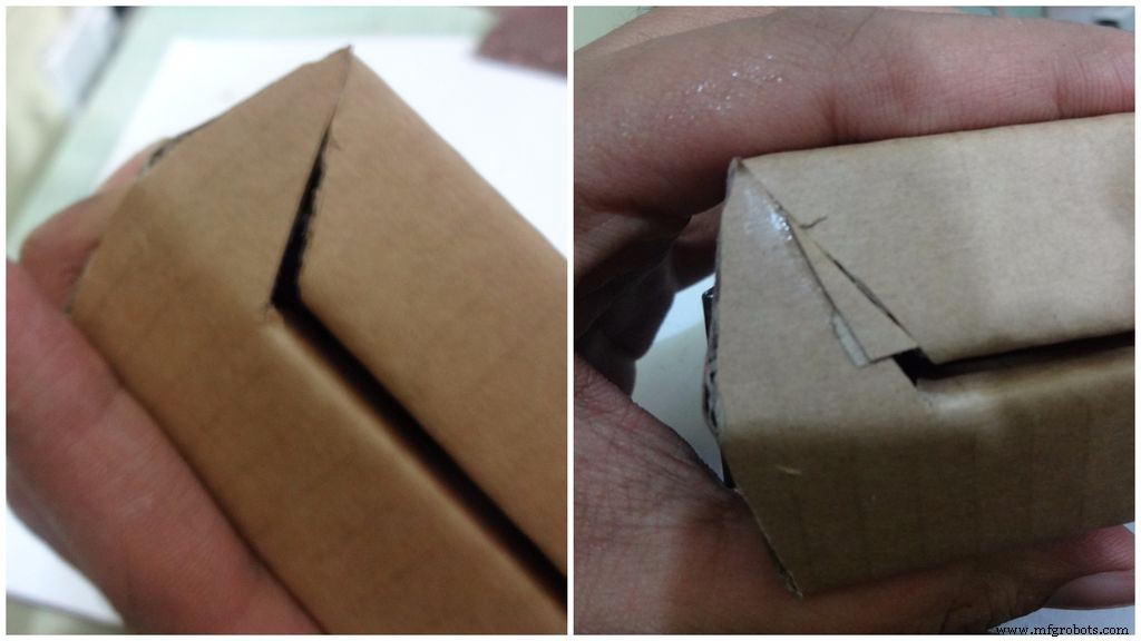
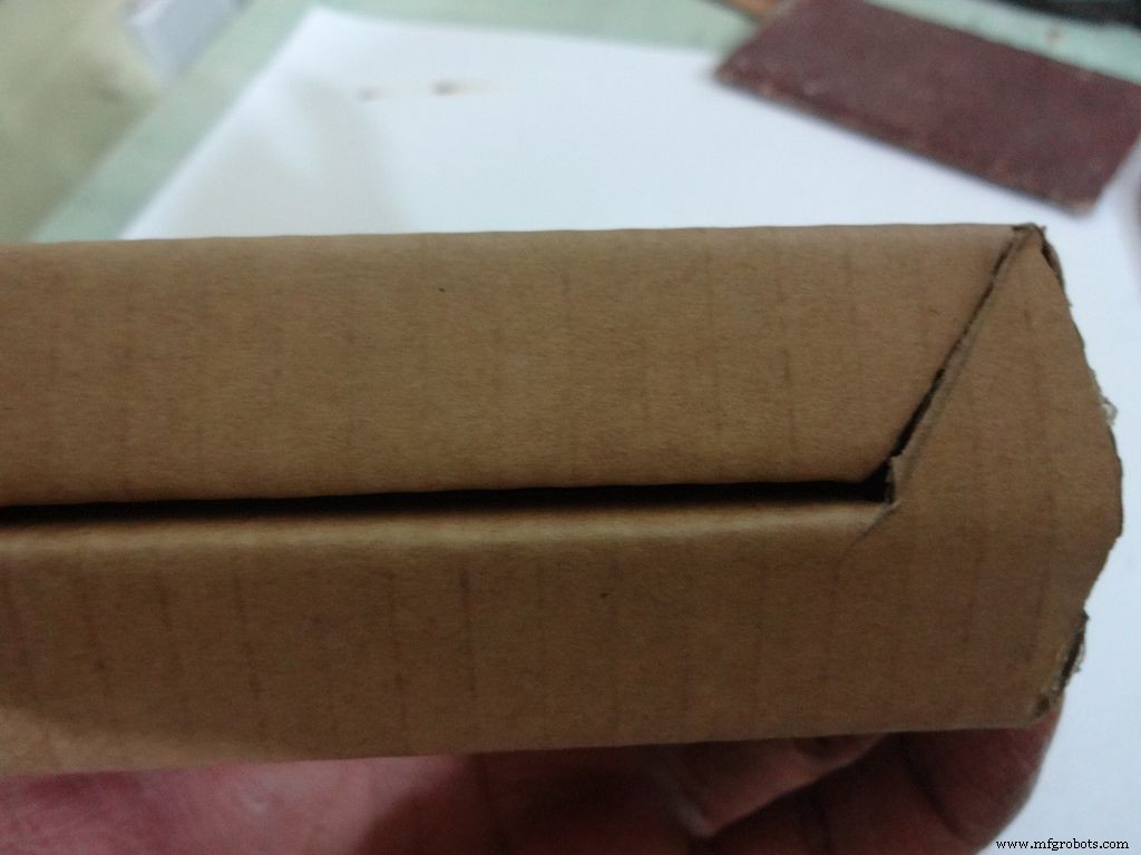
Sand, trim and close the tringular flap.
Make a small piece as shown and stick it to the cover. Make two holes, widen them with a pencil for inserting the bolt and locking the cover to the base.
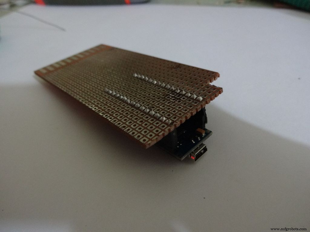
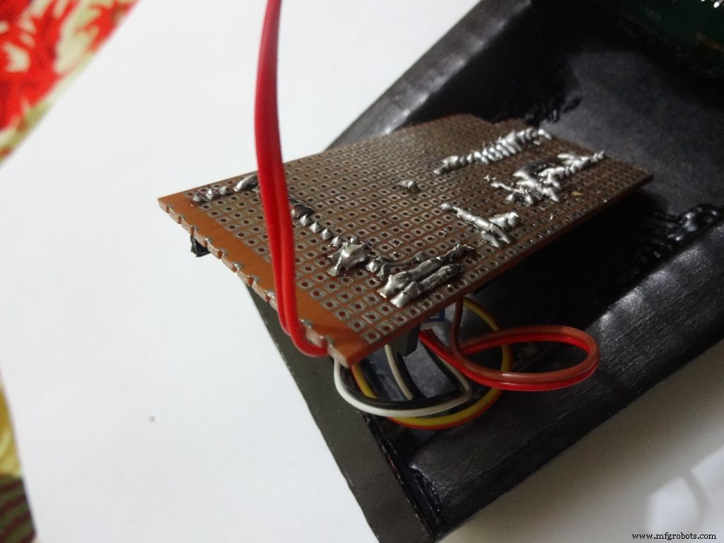
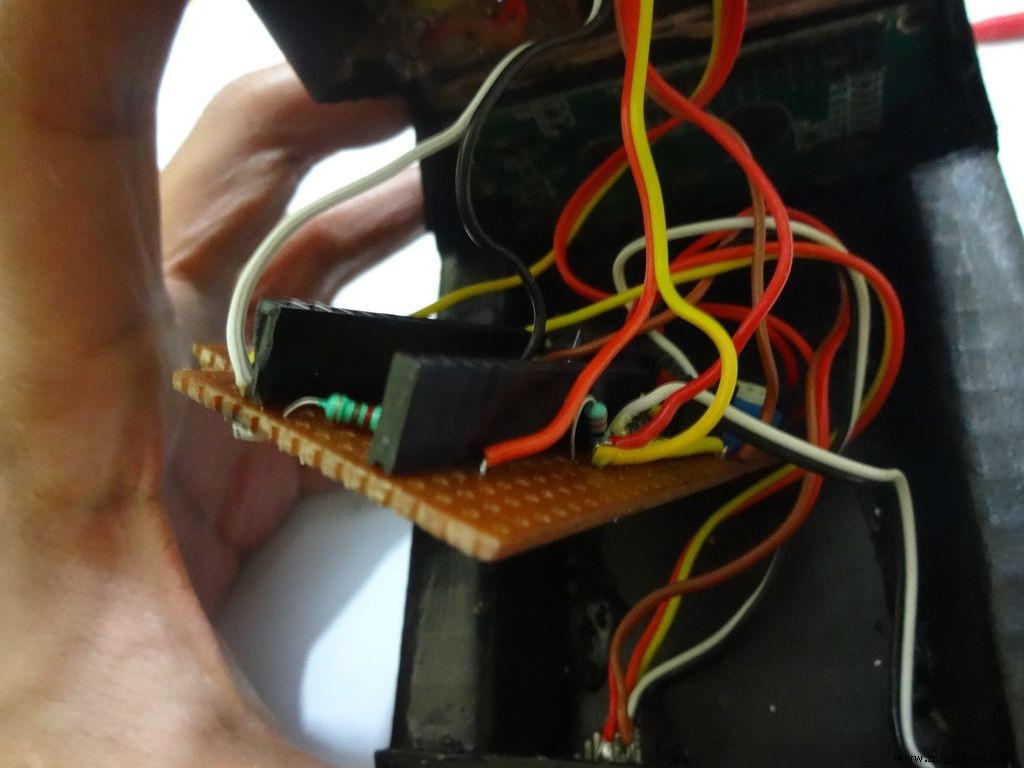
Step 14:The Circuit Board -- Making it fit

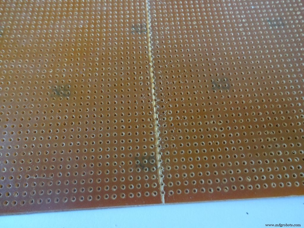
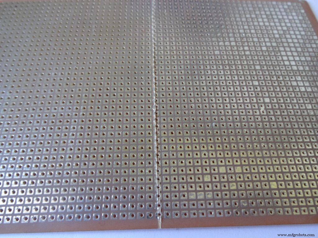
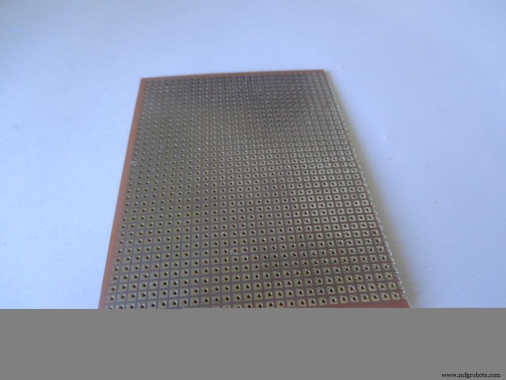
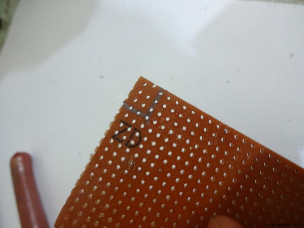
Cut the General purpose PCB to the right size such that it fits properly in the case. Mine is 2x4inches. To cut it, use the ruler and cutter and swipe it multiple times on both sides and it breaks off easily then.
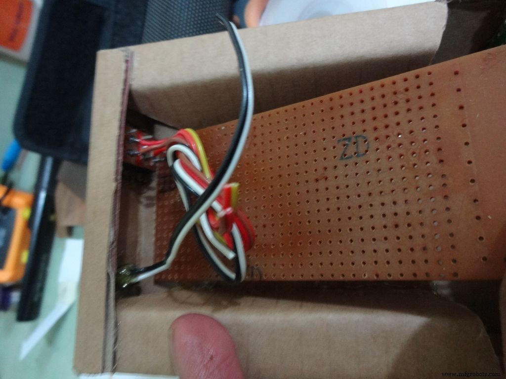
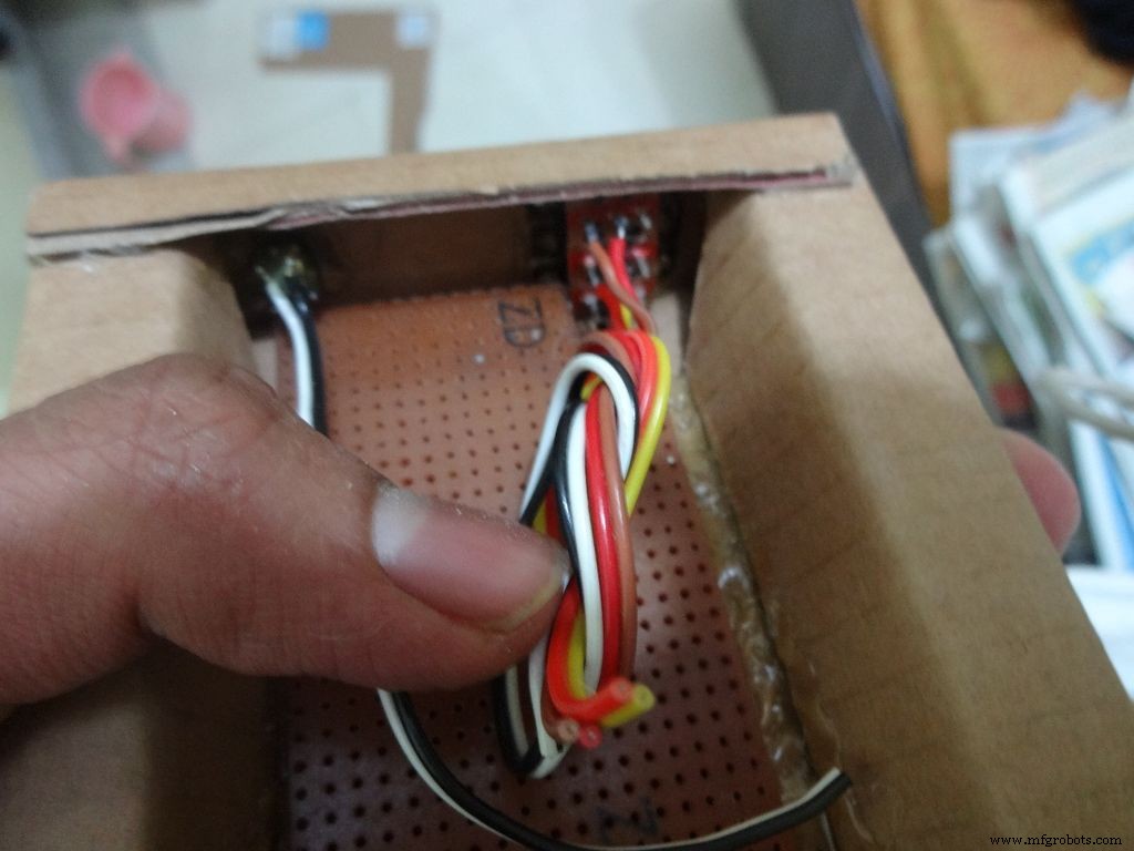
Place it inside. If the glue from the side flap lifts the PCB up, reheat the glue to flatten it or lessen the size of PCB a bit.
Cut a small part so that the 3 switches fit in and PCB goes entirely inside.
Step 15:The Circuit Board -- Arduino Nano

Cut female header pins of the right size for the Arduino.
Place it at the center edge of the PCB and solder all the pins.
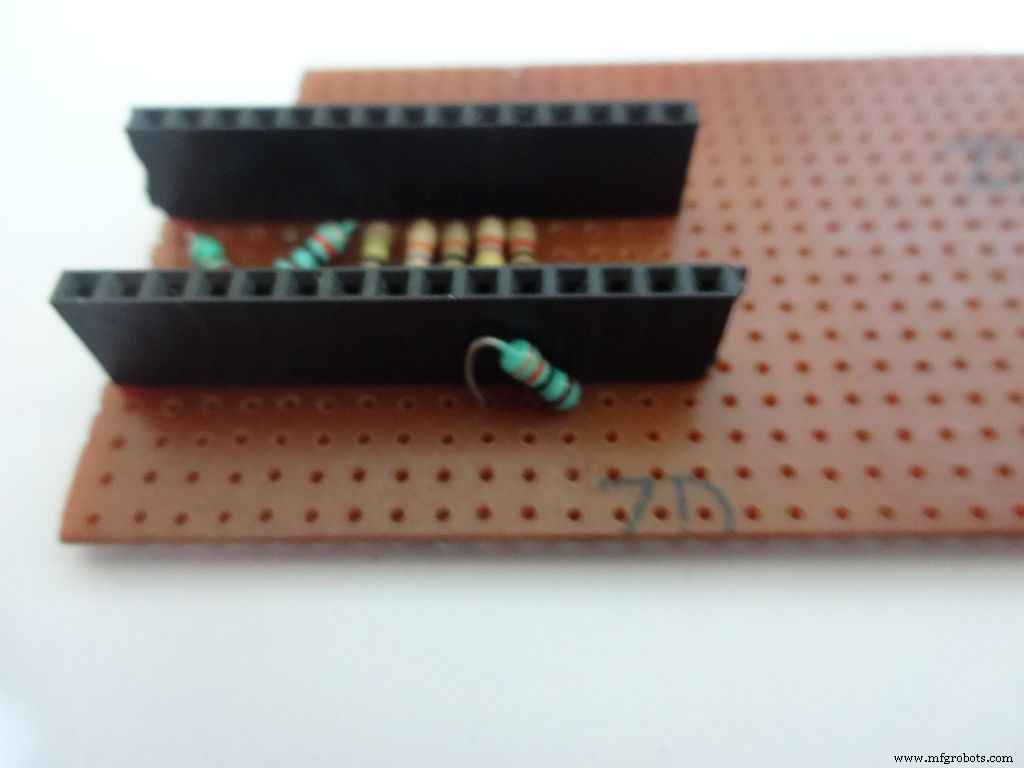
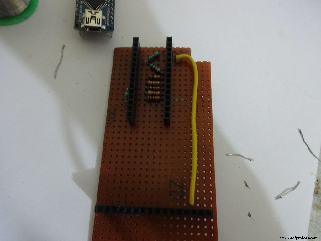
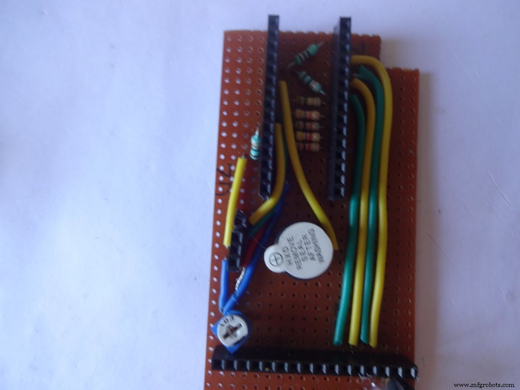
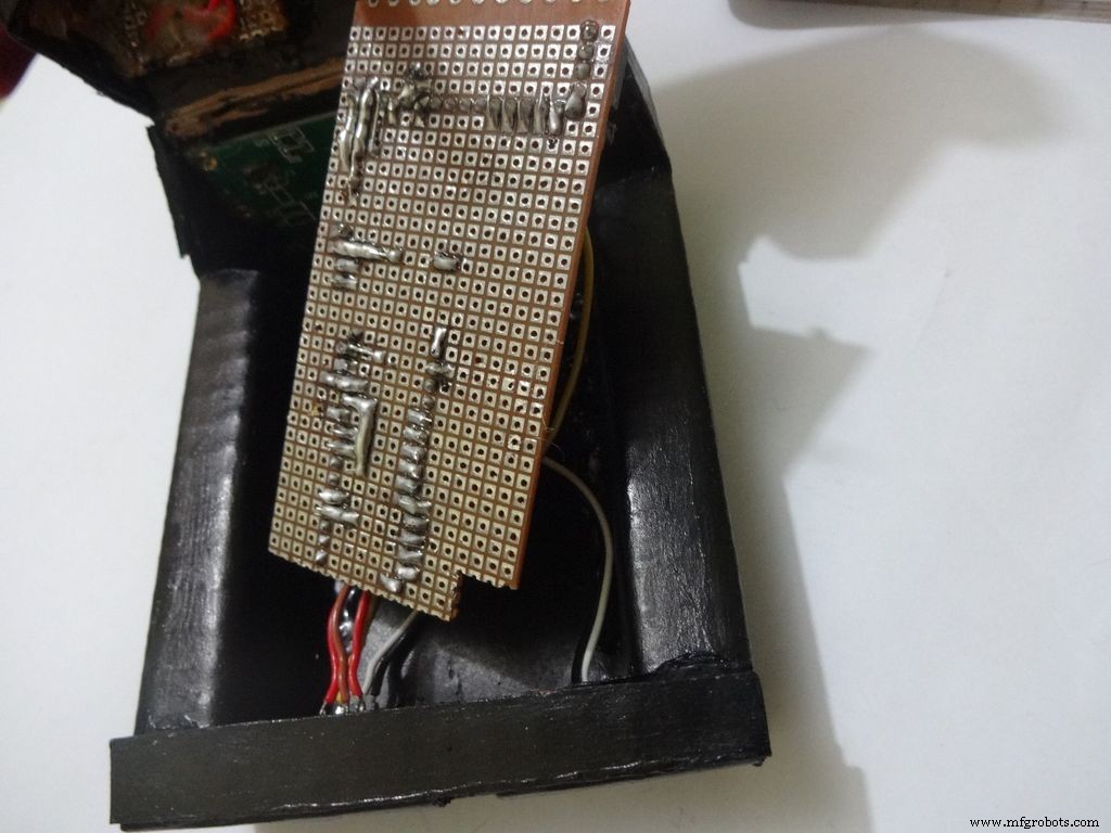
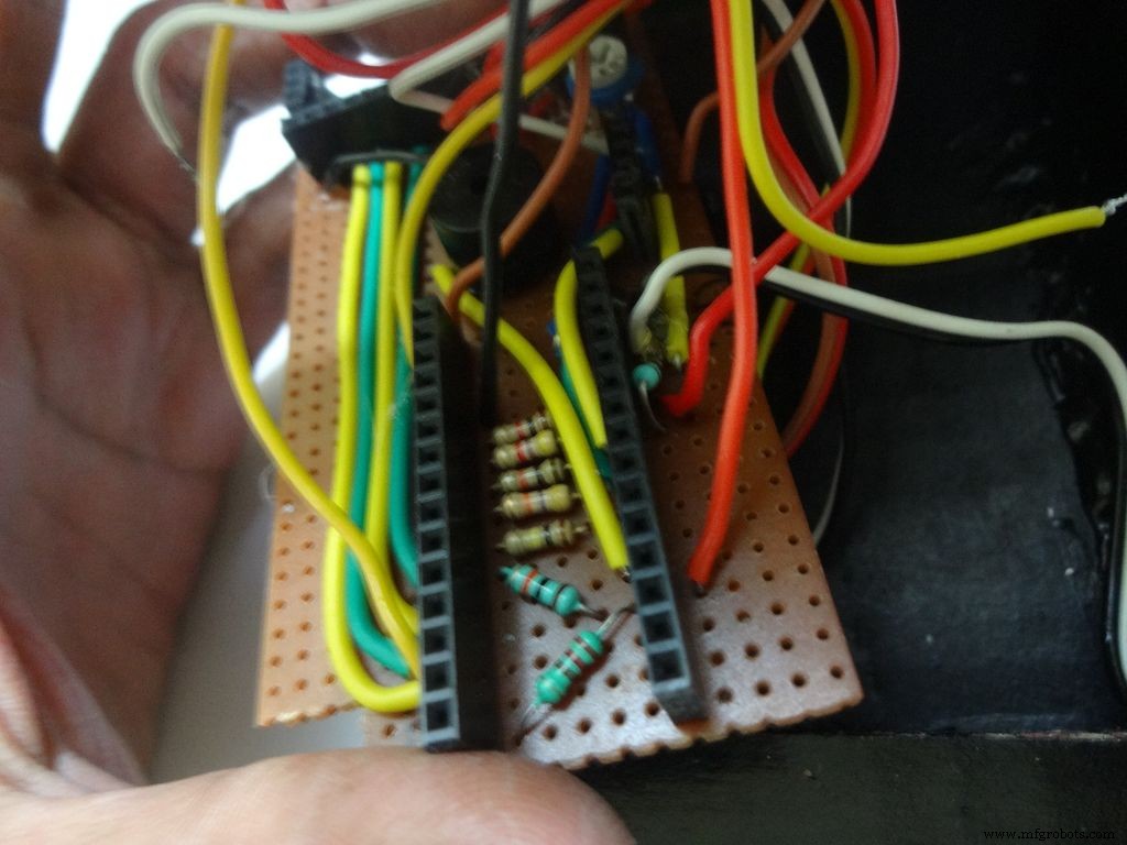
Step 16:The Circuit Board -- Ohmmeter
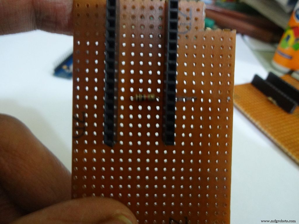
Before making any connections on the PCB please double check from the final Circuit Design.
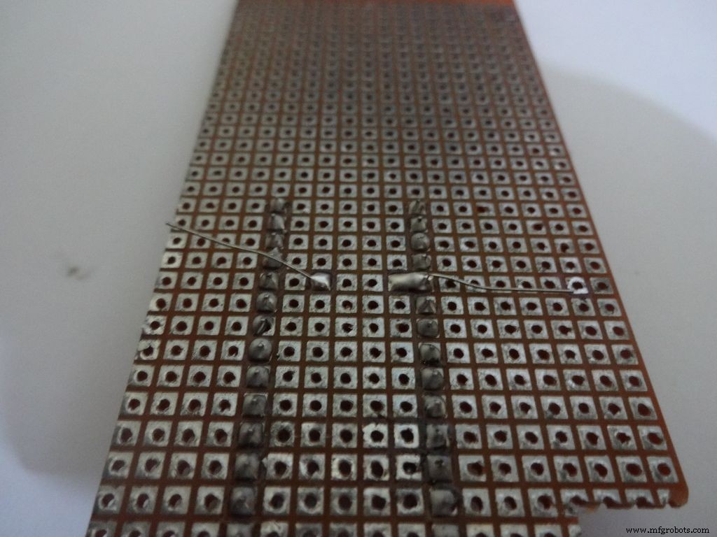
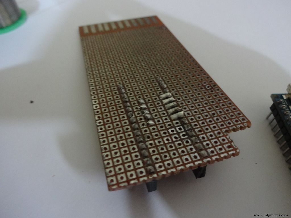
For the ohmmeter start by adding a 1k Ohm resistor to pin D2 of arduino. Place the arduino and carefully mark the pin. On the reverse side, bend as shown and solder it.
Do the same with the other 4 resistors, 4.7k, 10k, 47k and 100k Ohm.
Note:keeping all the tolerance bands(gold band) on one side is a good practice, eg UP and RIGHT.
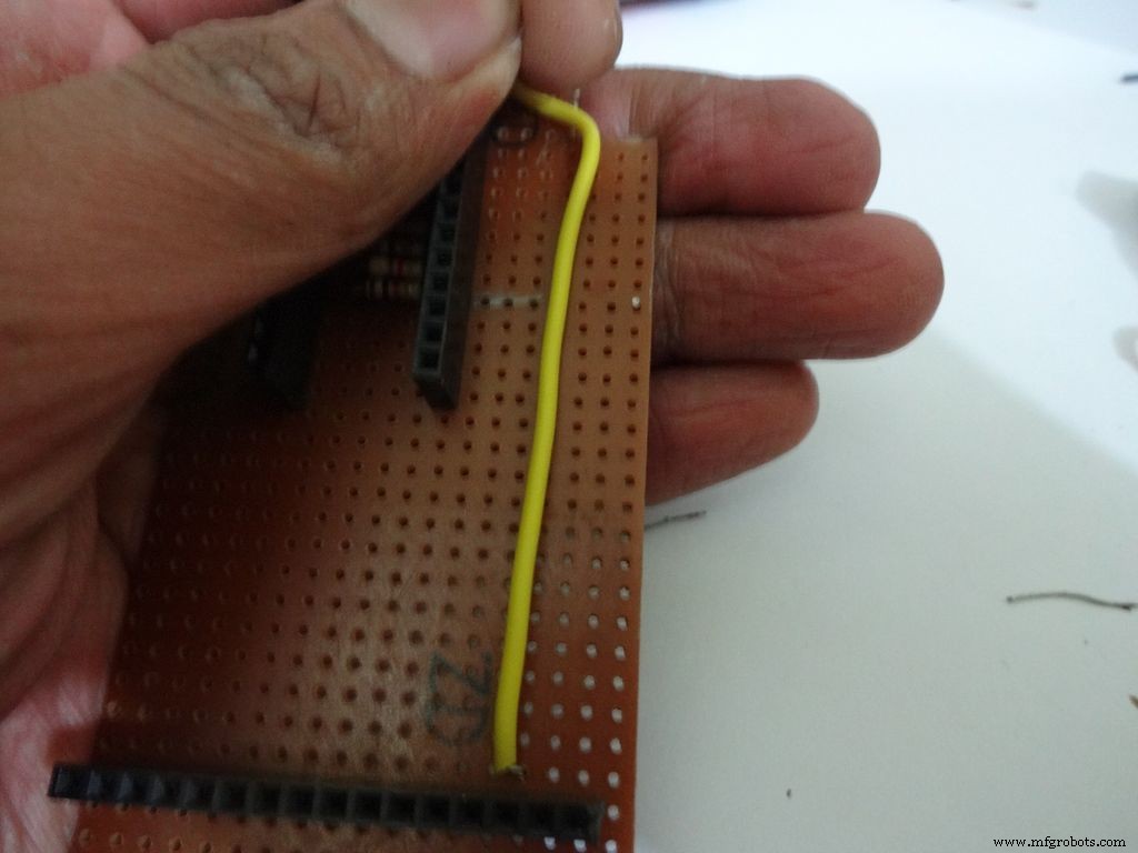
Combine the second ends of resistors and solder it to A7 .
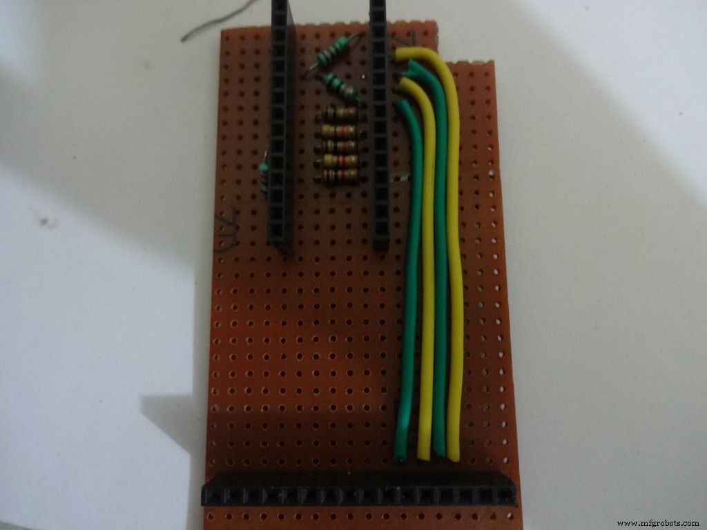
Step 17:The Circuit Board -- Capacitance Meter and Diode Test
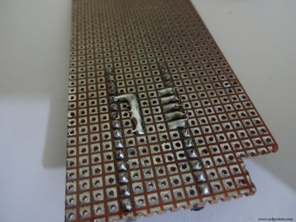
Capacitance Meter:
Solder a 220 Ohm resistor from D12 to A0 . And a 10k Ohm resistor from A0 to D7 .
Note: D7 (digital pin) is also used for LCD data pin D4 .
Diode Test:
Solder the 10k Ohm pullup resistor from A6 to +5V .
Step 18:Making connectors for LCD
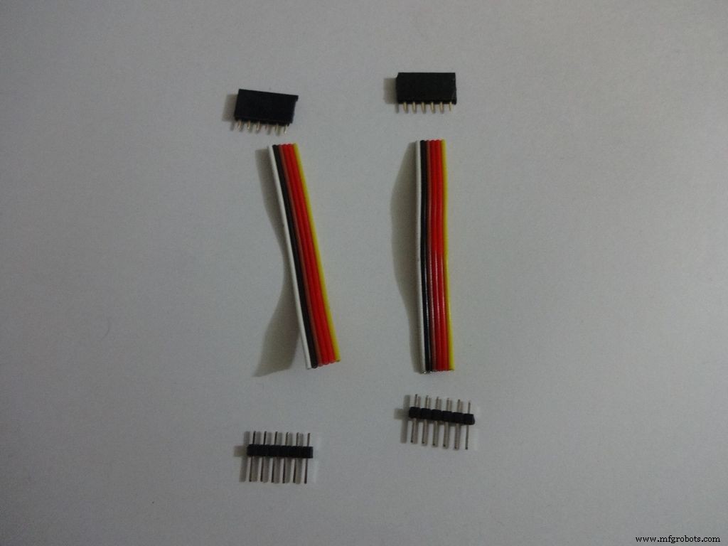
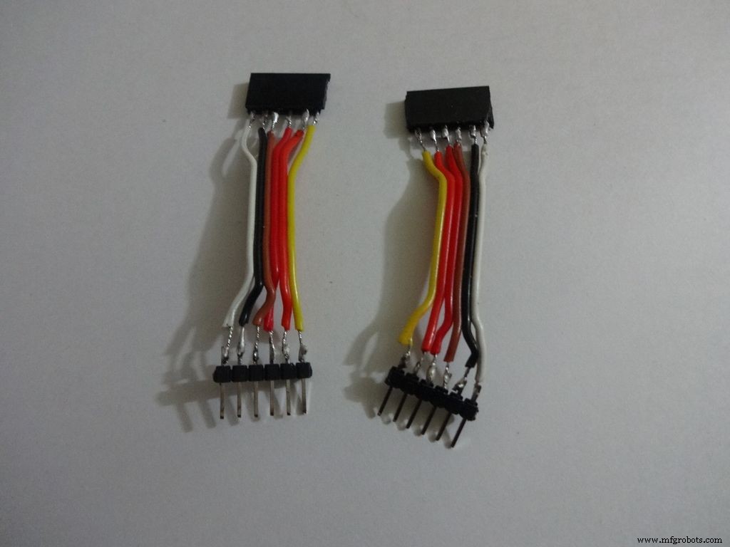
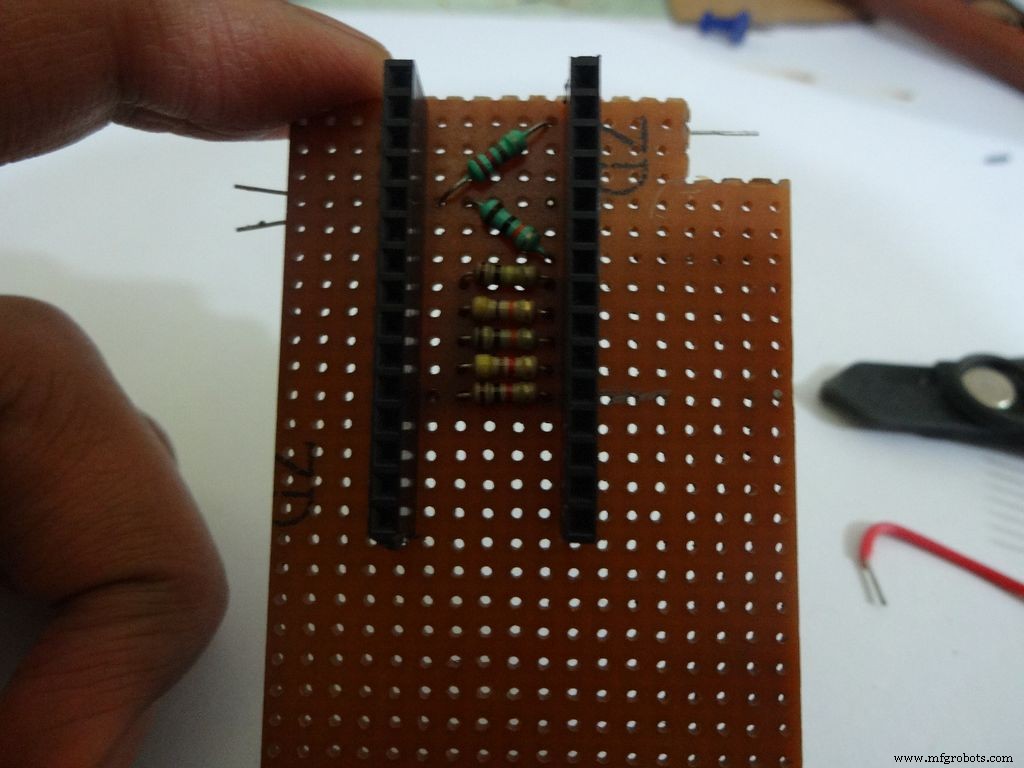
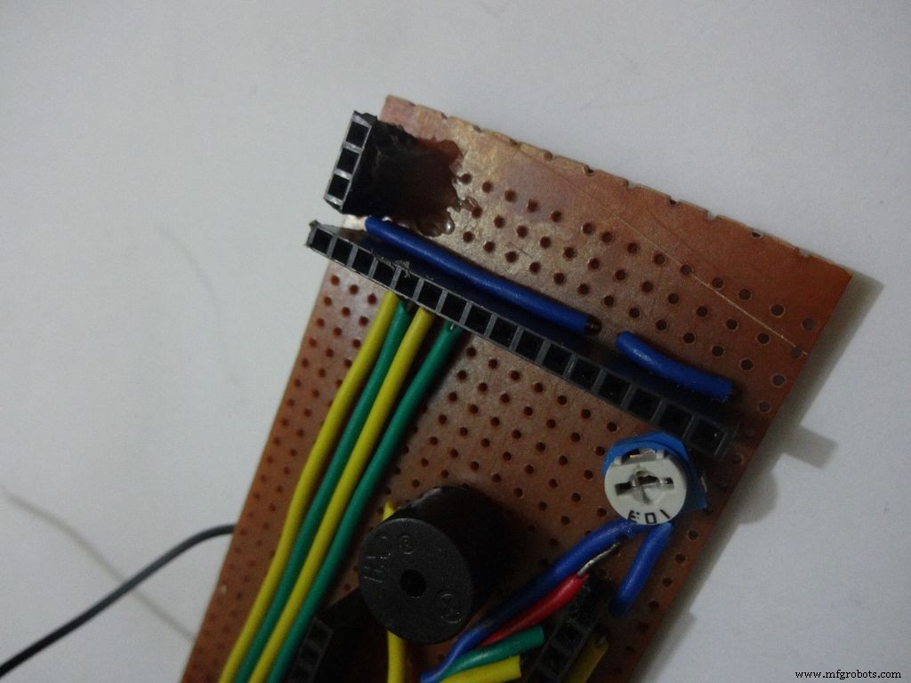
We just use the first 6 and last 6 pins on the LCD. Pins D0-D3 are unused. So we will be making connectors for only the used pins. It is recommended that you do the same because plugging/unplugging a 16pin connector becomes very tough once the build is complete.
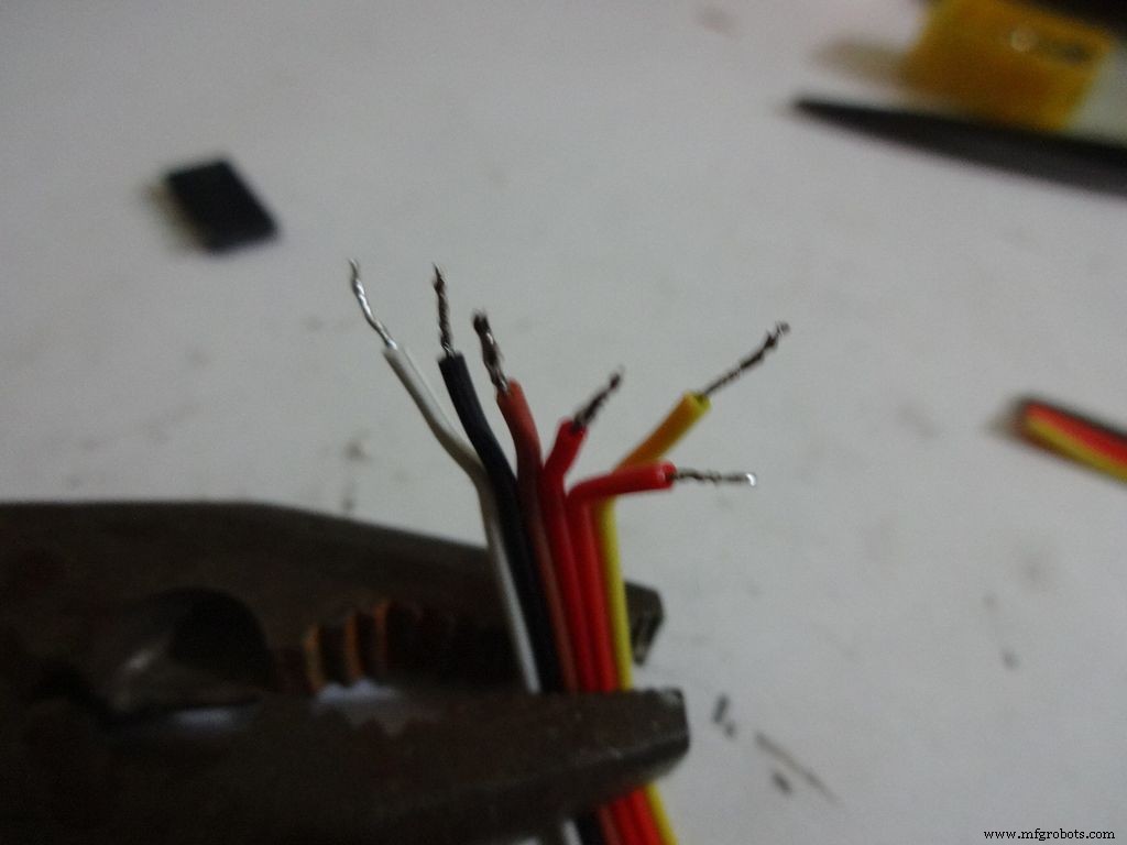
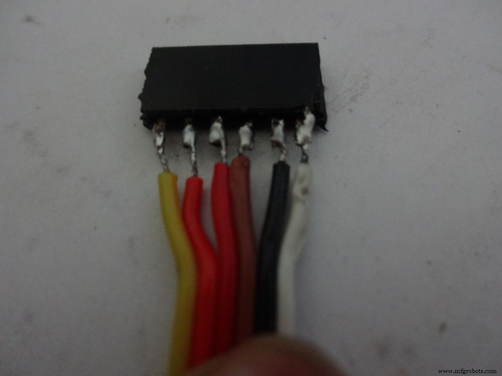
Cut 2x 6pin female and male header pins. Also take 6 wire ribbon cable, around 2-2.5 inches long.
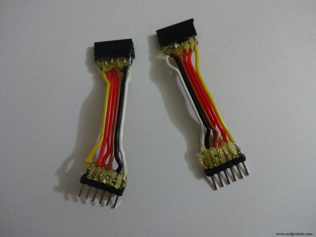
Strip the insulation and tin the leads. Also tin the header pins. Join them one by one just like the slide switches.
Apply hot glue to secure the wires.
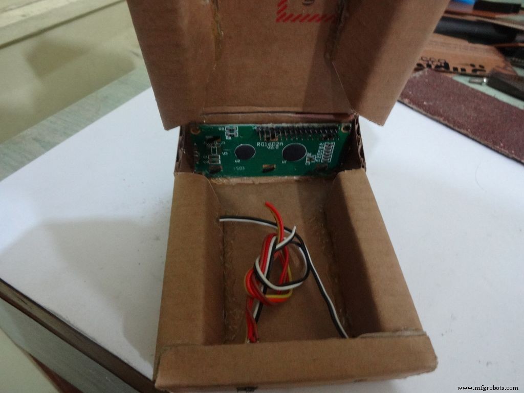
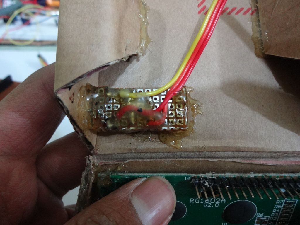
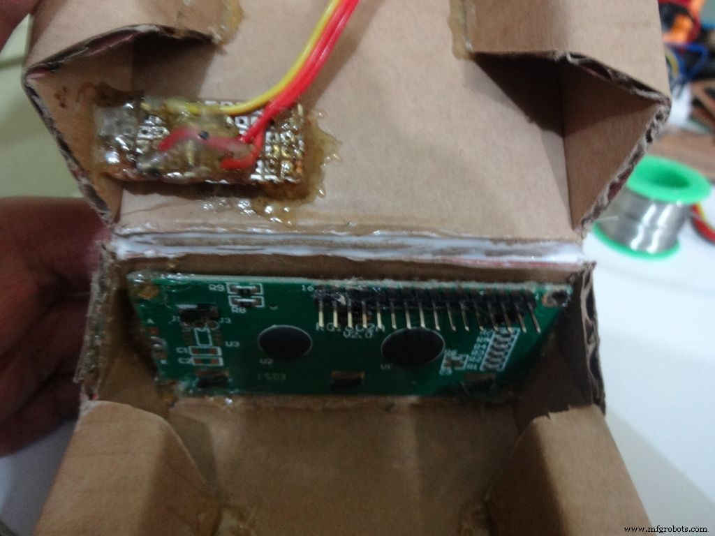
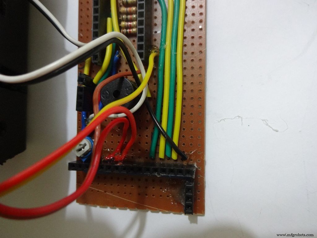
Step 19:The Circuit Board -- LCD connections
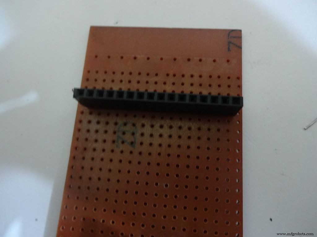
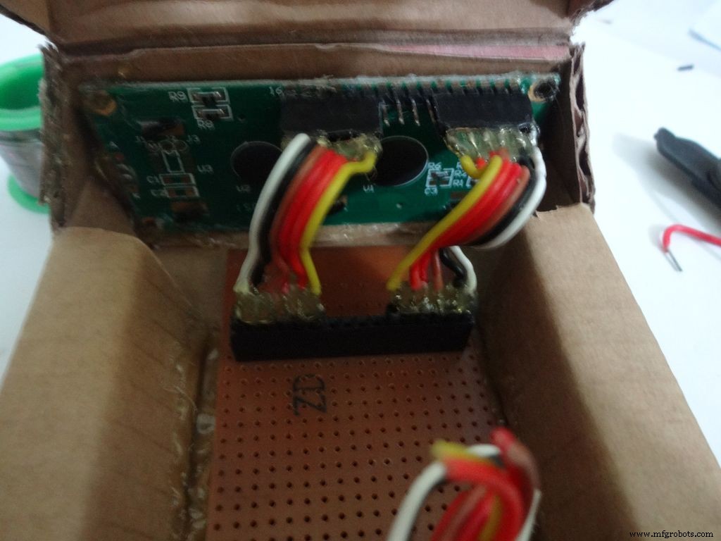

Place the PCB inside the case. Plug the connector to LCD and see where the female port should be on the PCB, solder it.
Make sure you leave 4-5 dot rows behind the LCD port. The Power switch will be added here later.
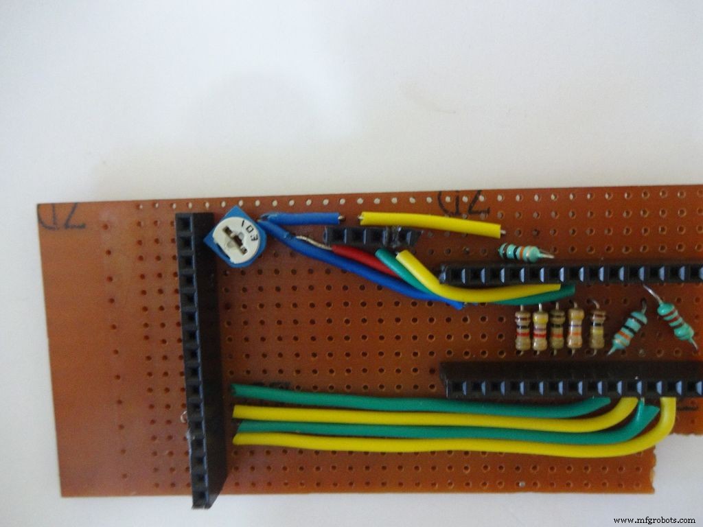
Measure the length of single stranded wire needed to connect data pins (D4 , D5 , D6 and D7 ) on the LCD to digital pins( D7 , D8 , D9 and D10 ) on the Arduino, respectively.
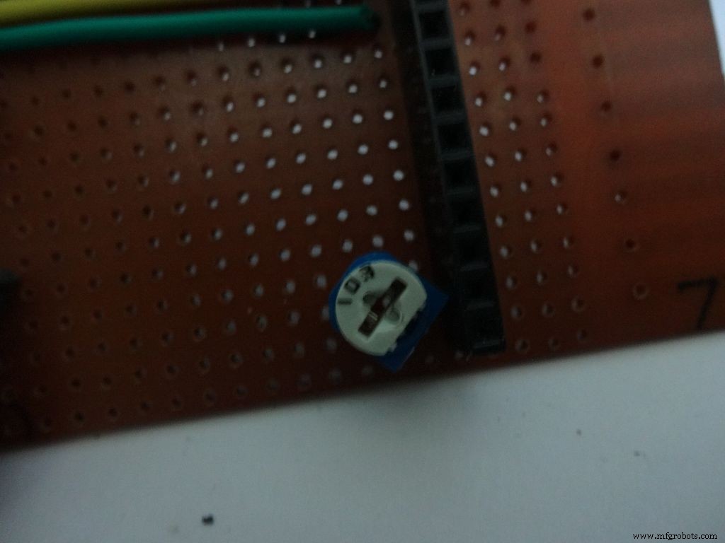
Add the 10k ohm potentiometer such that the side ends go to Vcc , GND and the middle pin to V0 .
Connect Vss(GND) on the LCD to GND , and Vdd to +5V . Also connect R/W 到地 .
Arduino Pin
LCD
D7 D4 D8 D5 D9 D6 D10 D7 GND Vss(GND) +5V Vdd
Step 20:The Circuit Board -- RTC Module
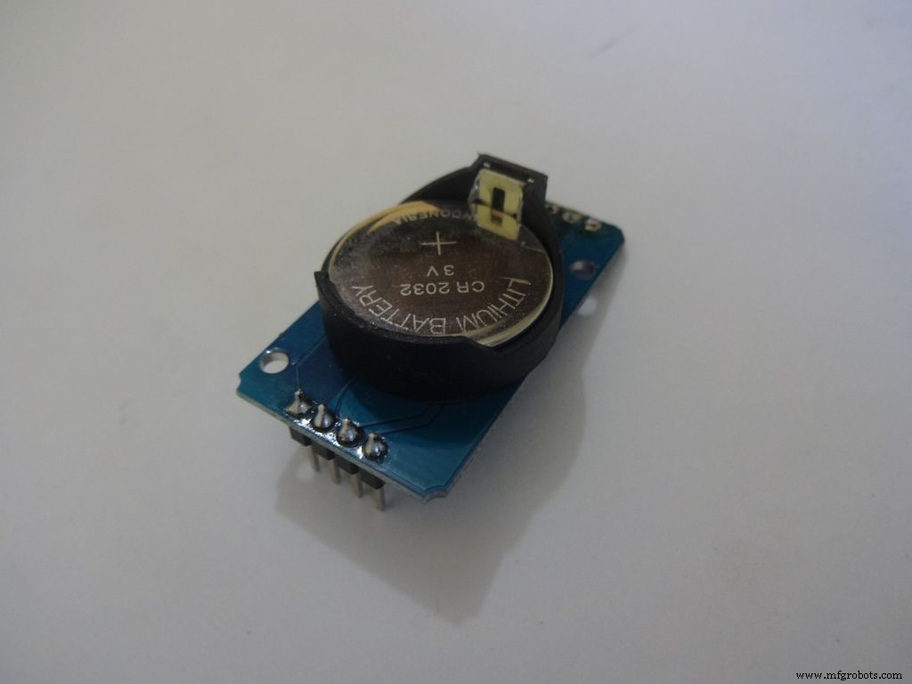
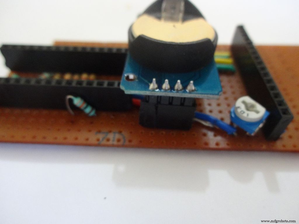
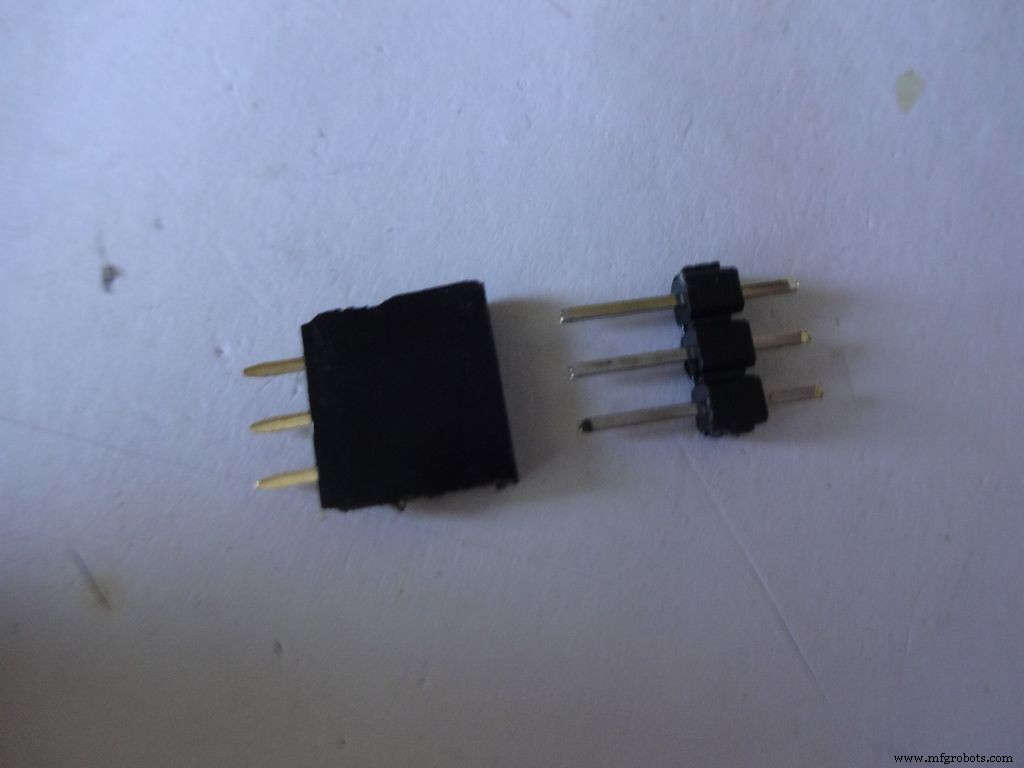
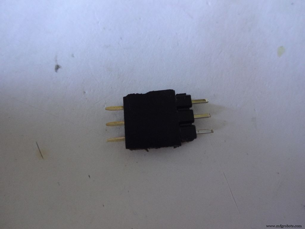
I desoldered the default 90 degree header pins on the module and added straight ones so that it fits flat on the PCB.
Solder 4pin female header pin and make connections to Vcc , GND , SDA to A4 and SCL to A5 .
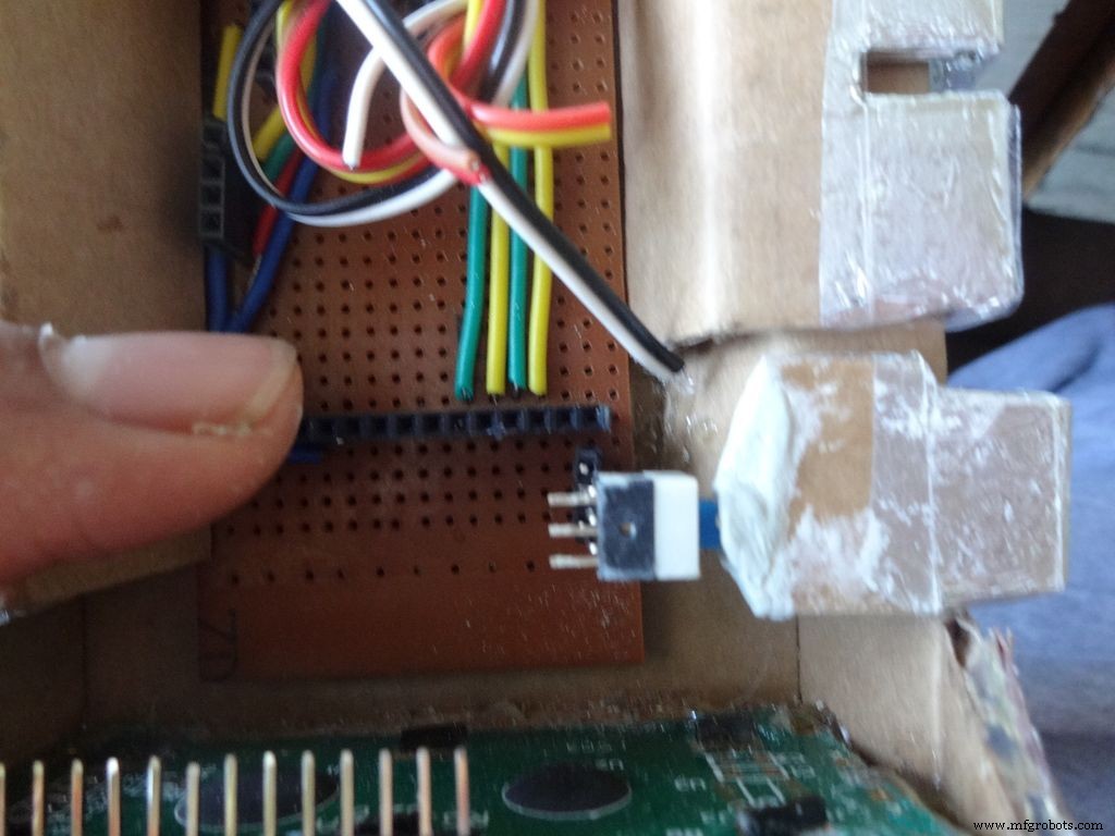
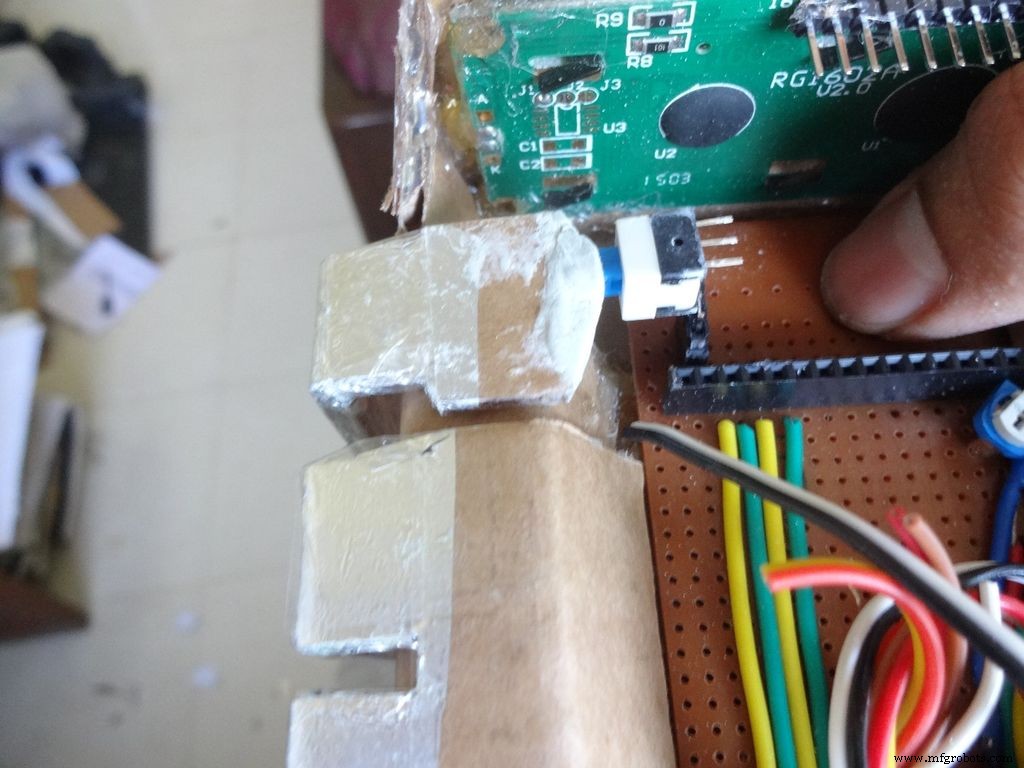
Step 21:Making the Case -- The mode button
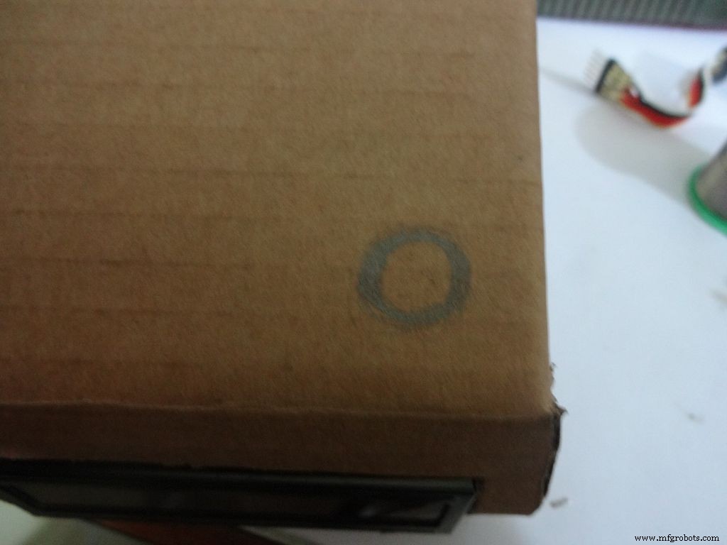
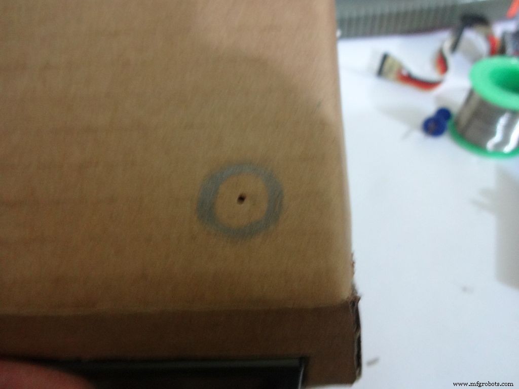
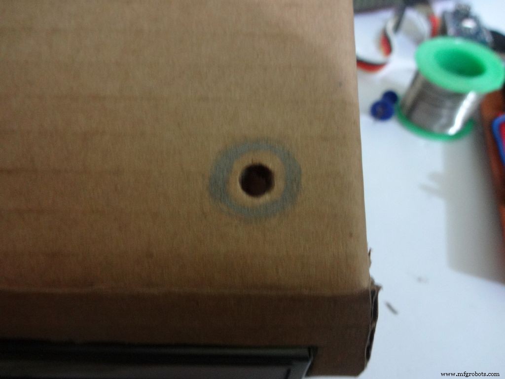
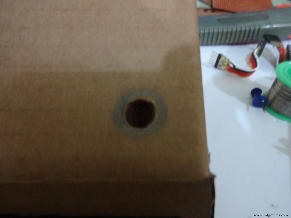
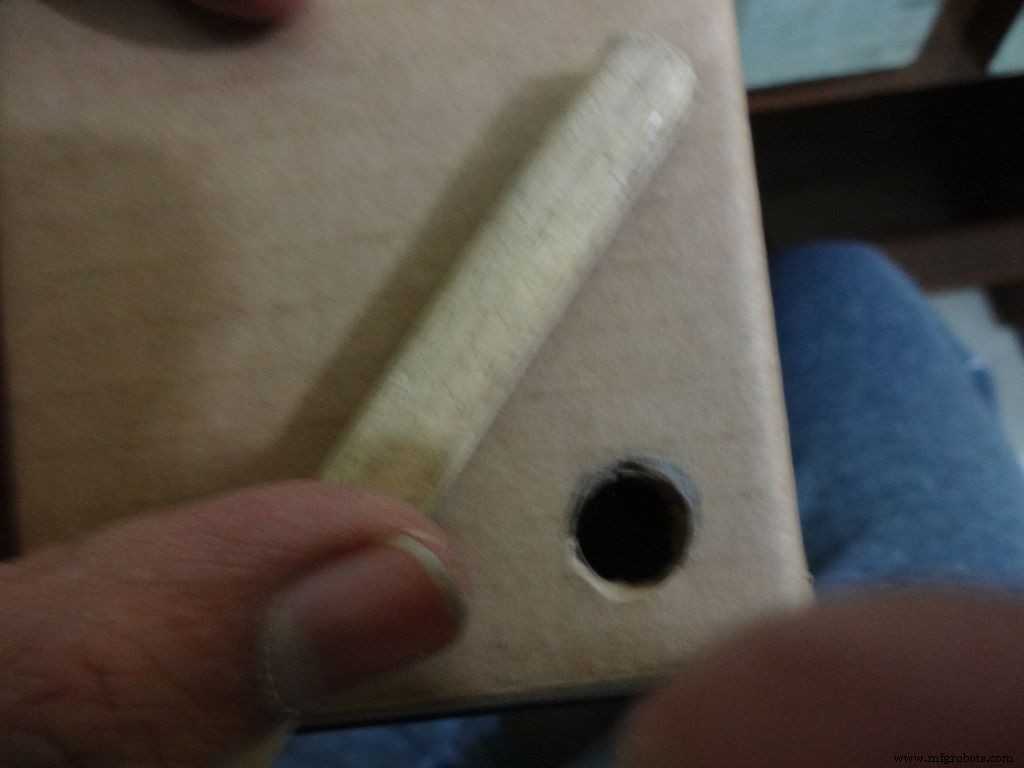
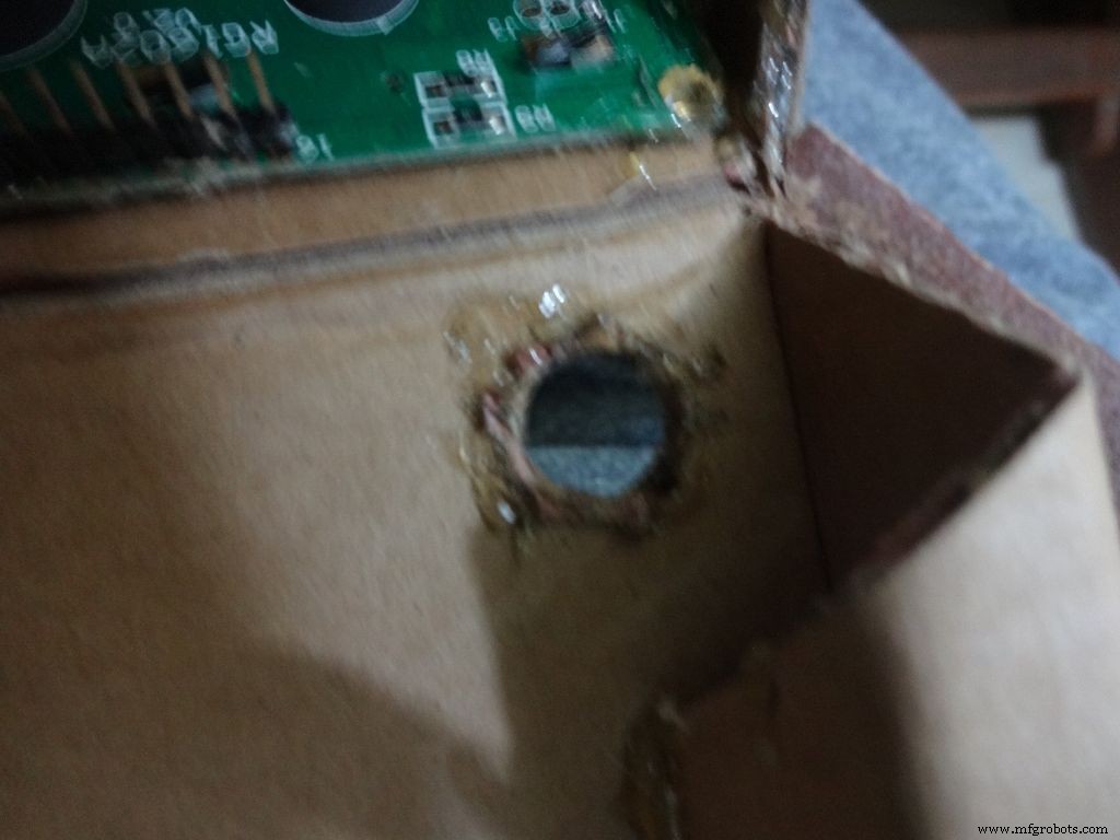


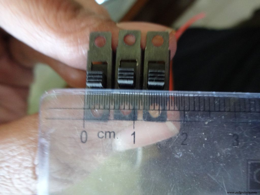
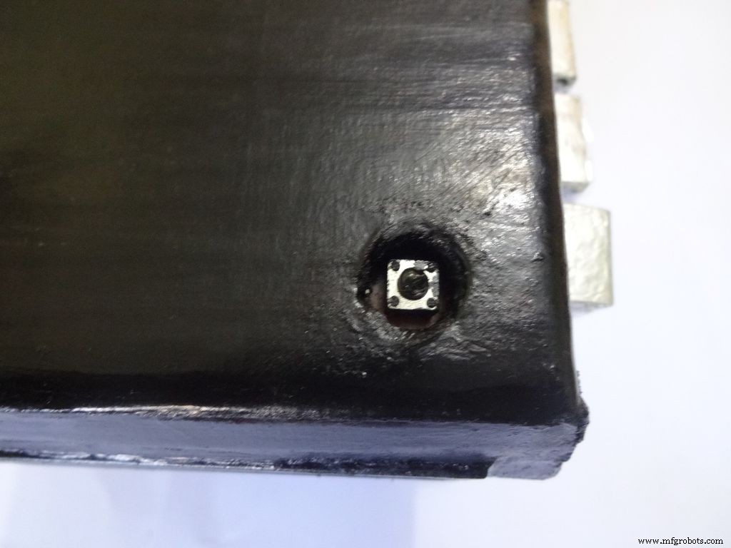
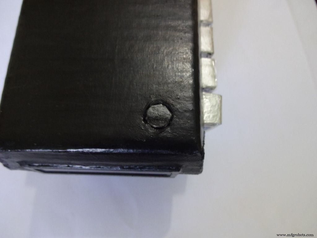
Mark a circle of about 1cm diameter at the pin1 corner of the IC case. mark the center with a pin, use a pencil to expand it. After that use some appropriate tool to increase the diameter to 1cm. Sand it on the inside and use hot glue to secure the hole.
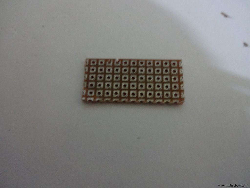
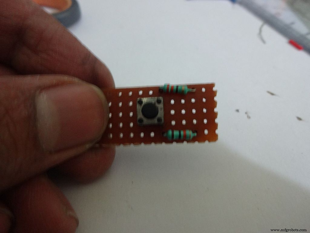
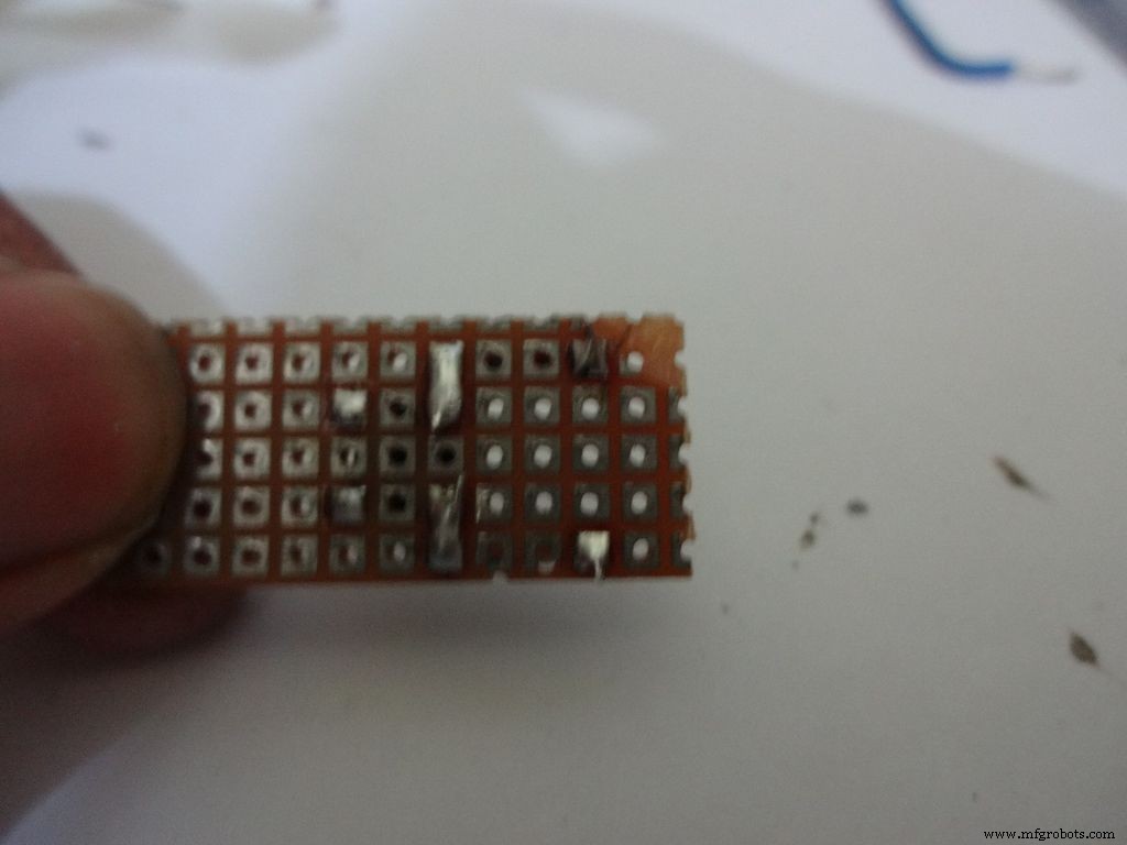
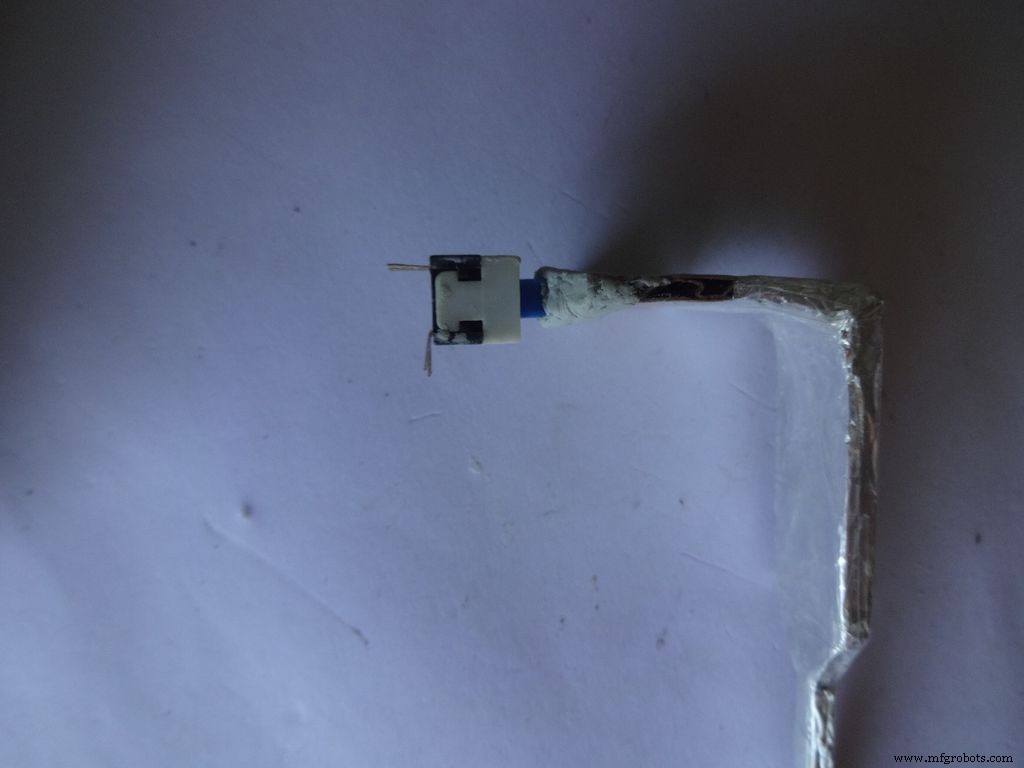
Cut a piece of General purpose PCB (10-11)dots x 5dots. Plug in and solder the pushbutton, 220 and 10k Ohm resistors as shown.
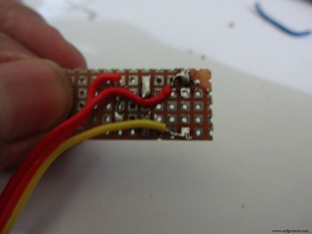
Take 3wire ribbon cable about 15cm long. Tin the ends and solder it as shown. Note down which colour wire goes to where, this will be helpful later on.
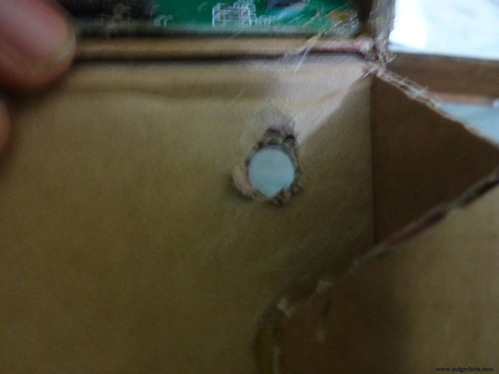
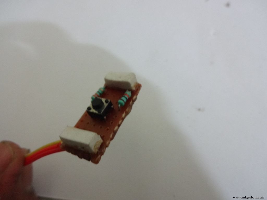
Cut 2 small pieces of eraser and place it on the ends on the board. The height of the eraser should be such that the button is below the cardboard inner level as viewed from outside. I used 4mm.
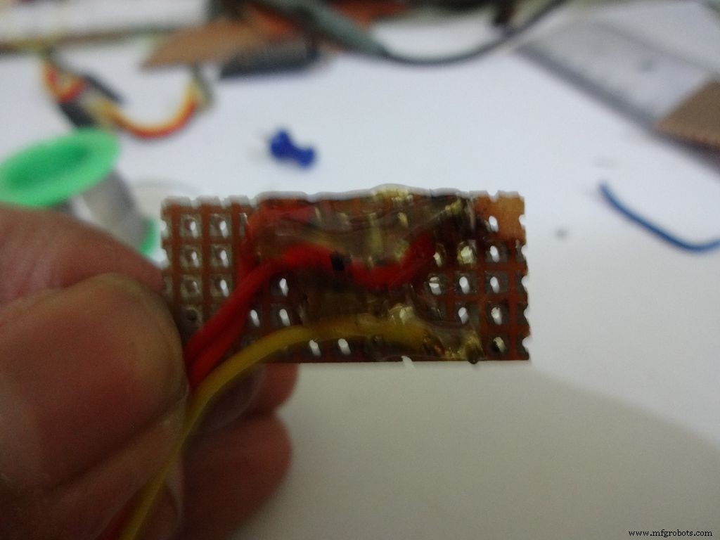
Secure it with hot glue as shown
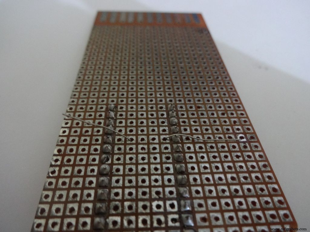
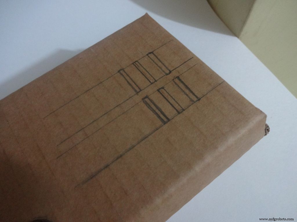
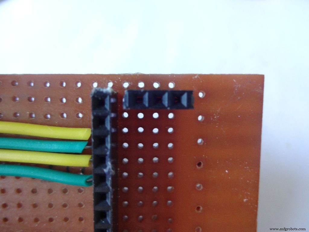
Step 22:Making the Case -- Testing points
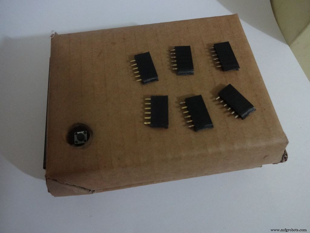
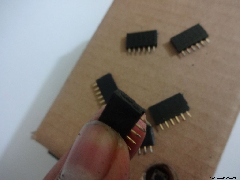
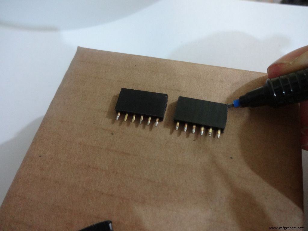
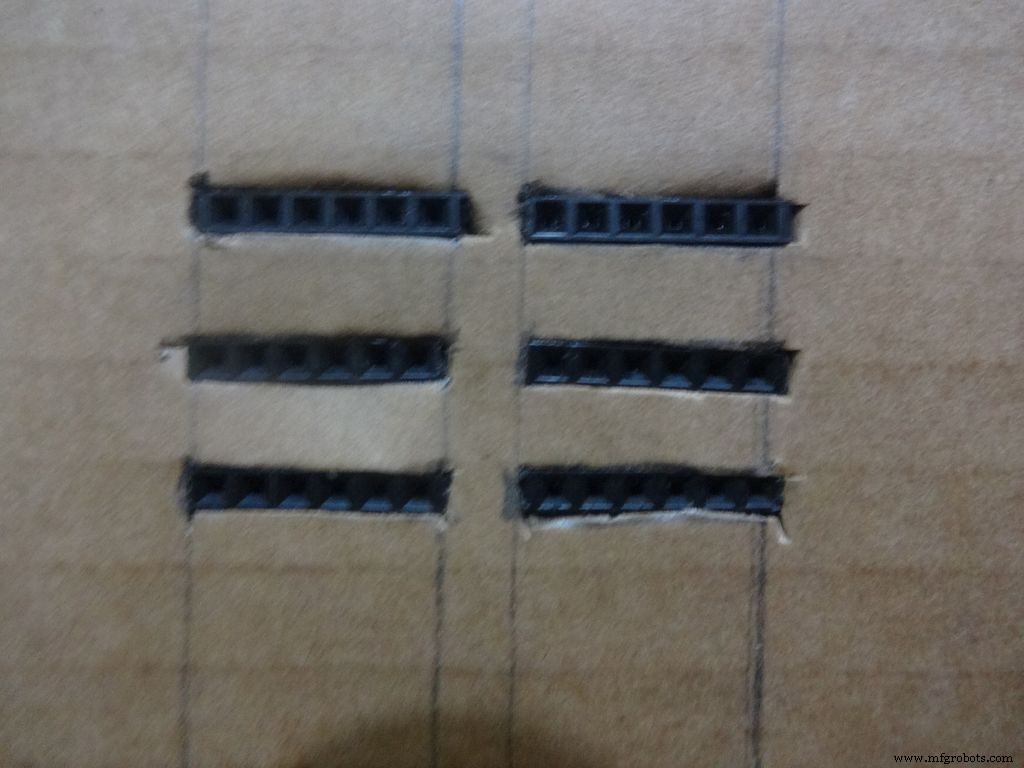
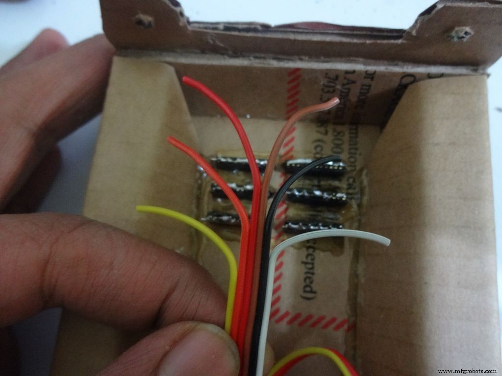
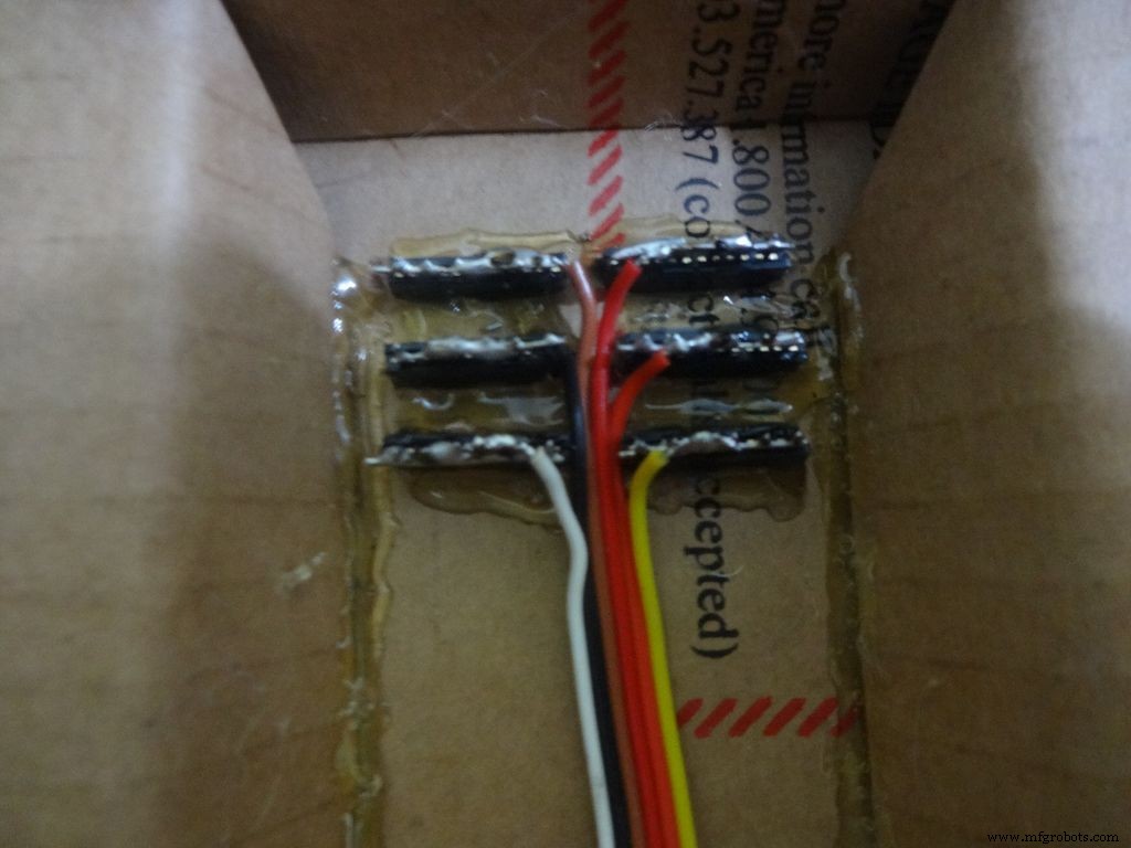
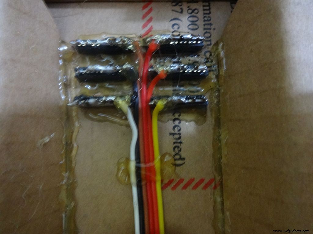
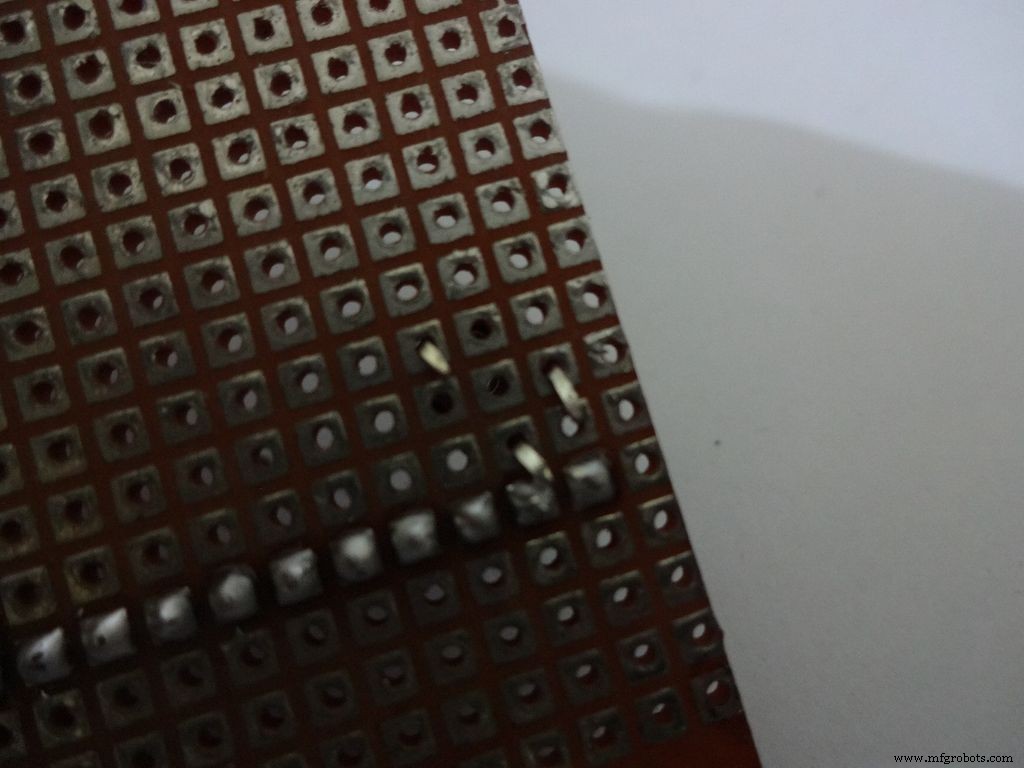
Cut 6x 6pin female header pins. Sand the sides to make it smooth.
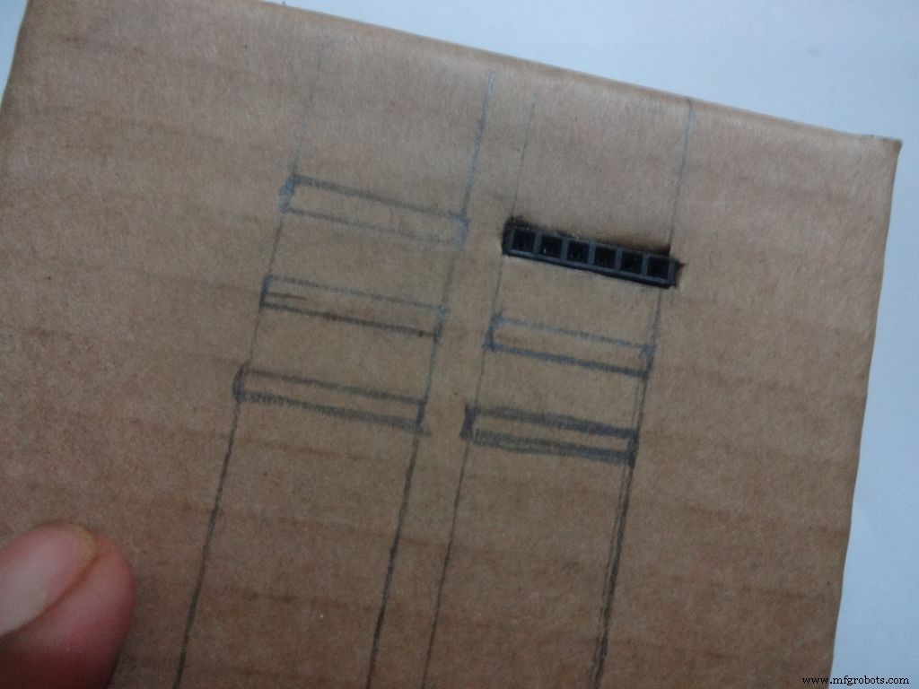
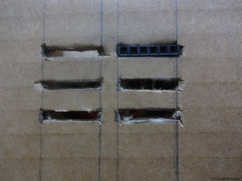
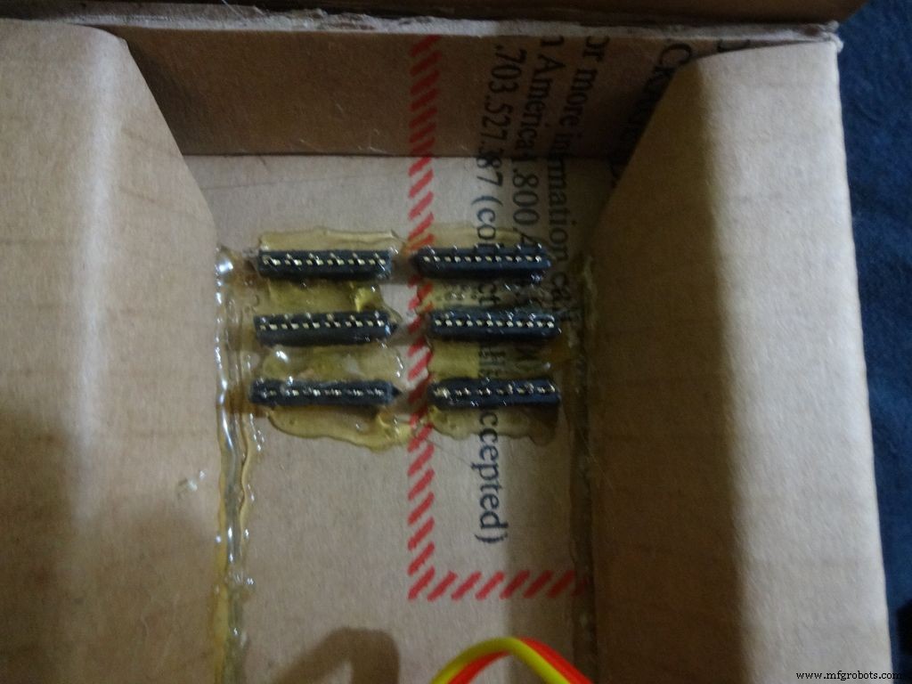
Mark the positions and cut slots for the header pins. Insert it in place and glue it from the inside.
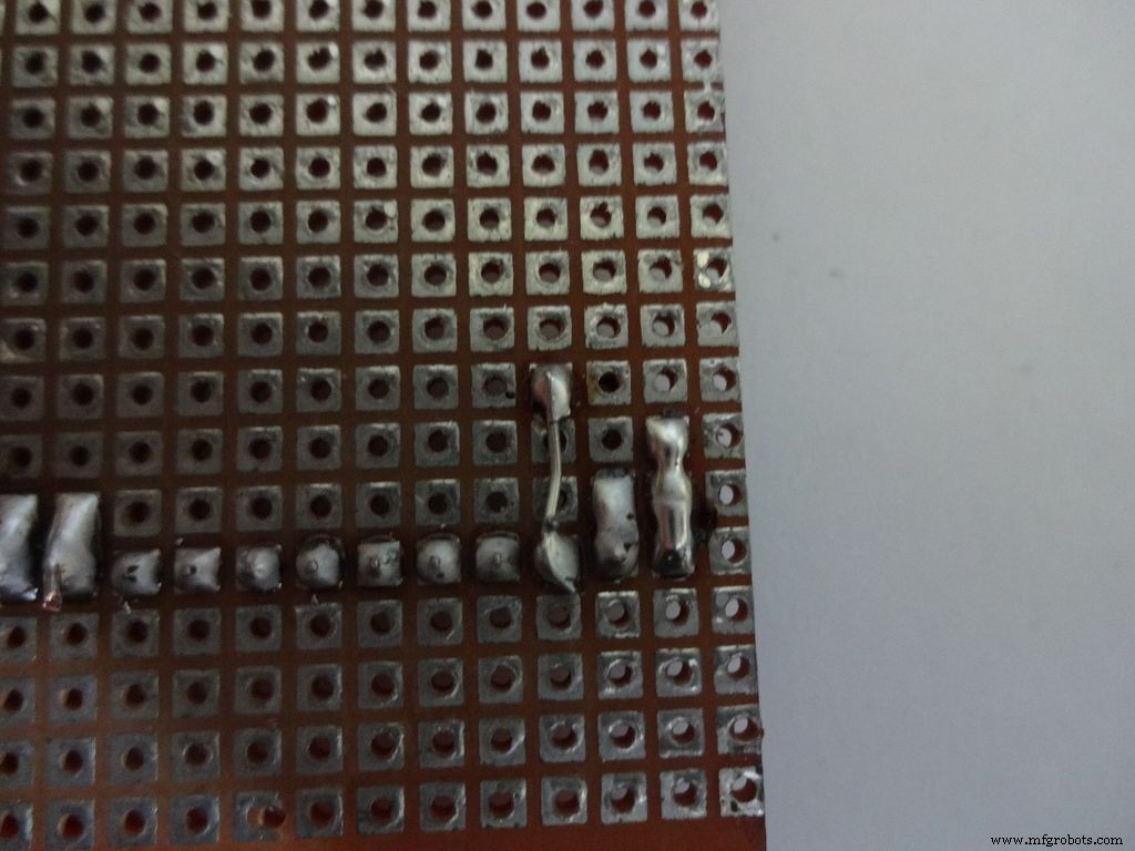
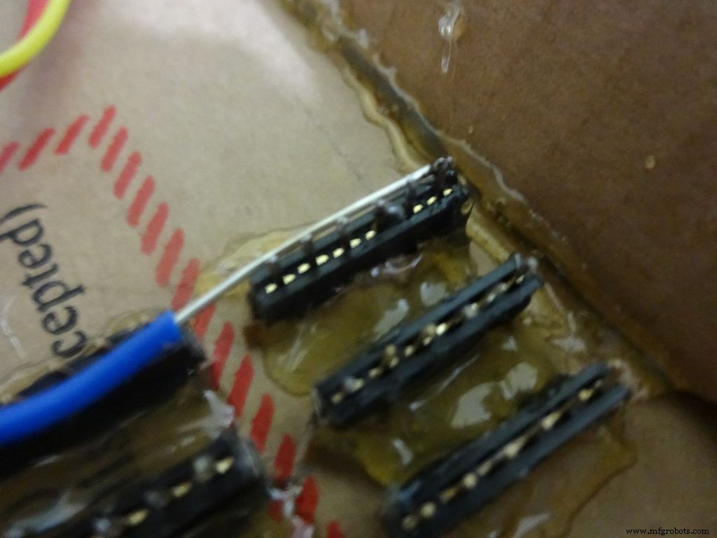
Apply small amounts of solder to all the pins and use a stripped jumper to get it all together. Make sure all of them are connected. Dont keep on heating it to make it perfect. Heating a pin also heats the neighbouring ones.
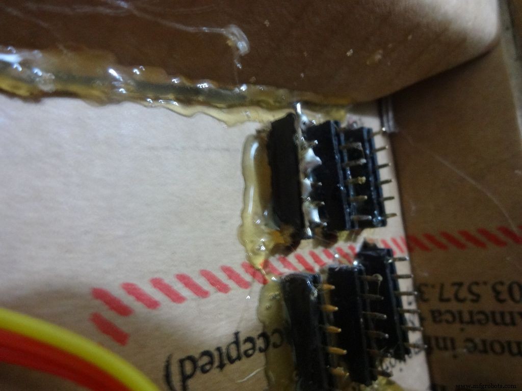
Take 6 stranded ribbon cable, tin it and attach it to each slot. Note that I put dark colours to the negative side. Apply hot glue to fix them in place.
Step 23:The Legs


Download "Legs_A4.pdf" or ""Legs_ANSI_A.pdf", based of paper size available in your region. attached at the end.
Print it on an A4 size paper (21 x 29.7cm or 8.27 x 11.69 inches) or the US-alternative ANSI A(8.5 x 11inches or 21.6 × 27.9cm). Make sure that while printing you select the proper paper size, orientation, and select the "Actual Size" option. Confirm that the print is accurate by measuring the rectangle. It should be 8.4 x 11.8cm
Cut crease and glue it just like the main case, see the images.
Step 24:Making it shiny!
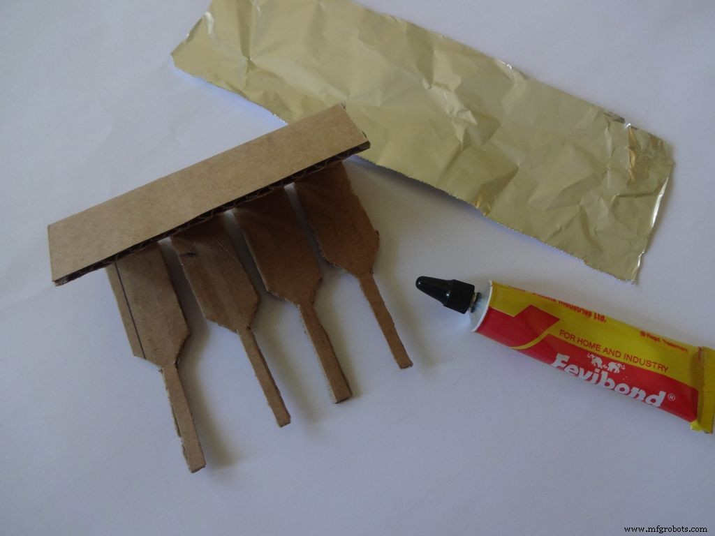
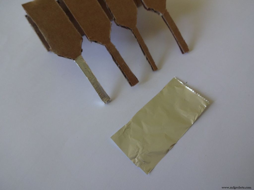
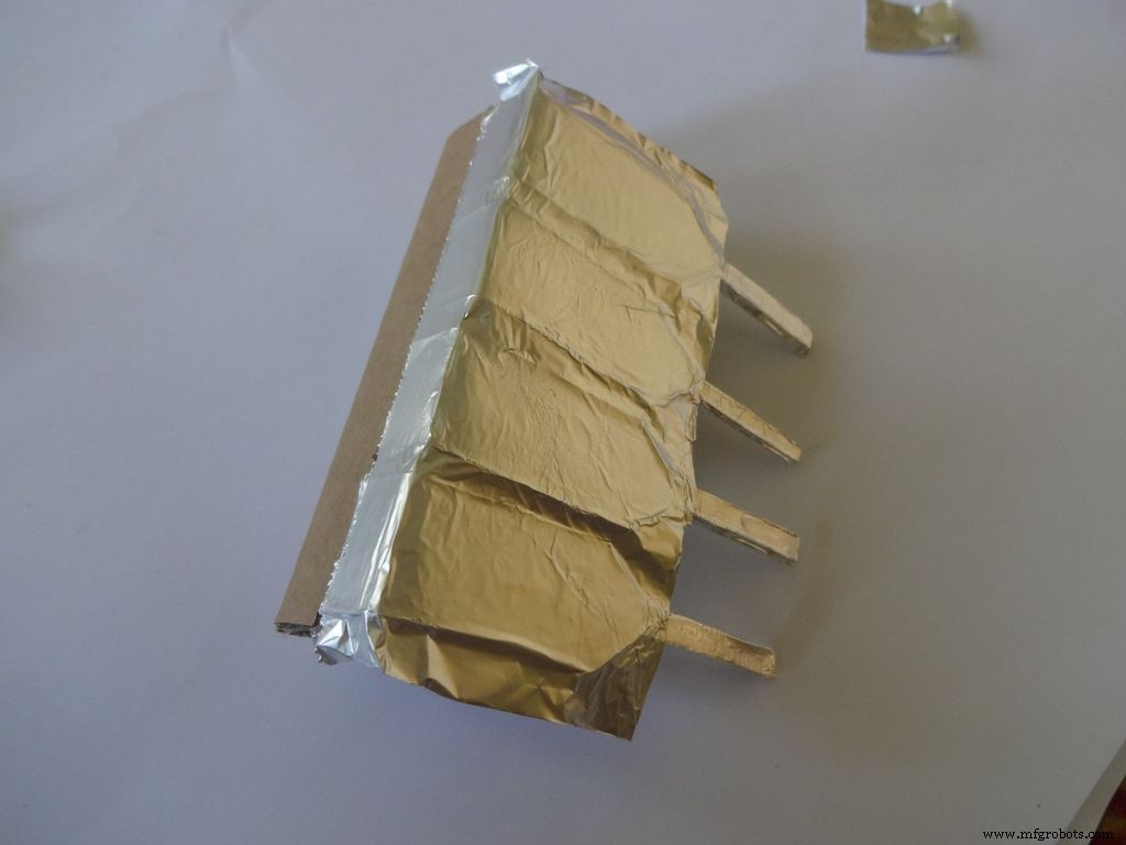
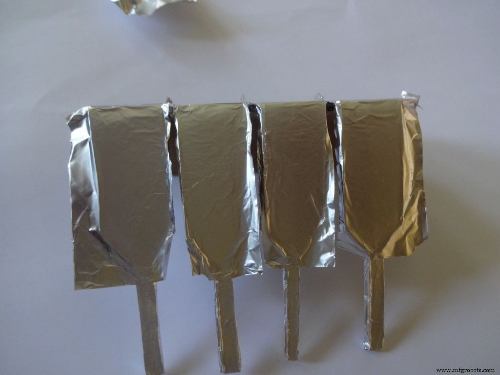
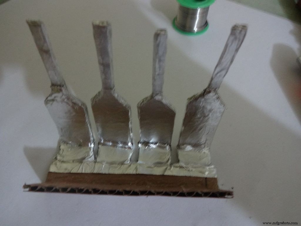
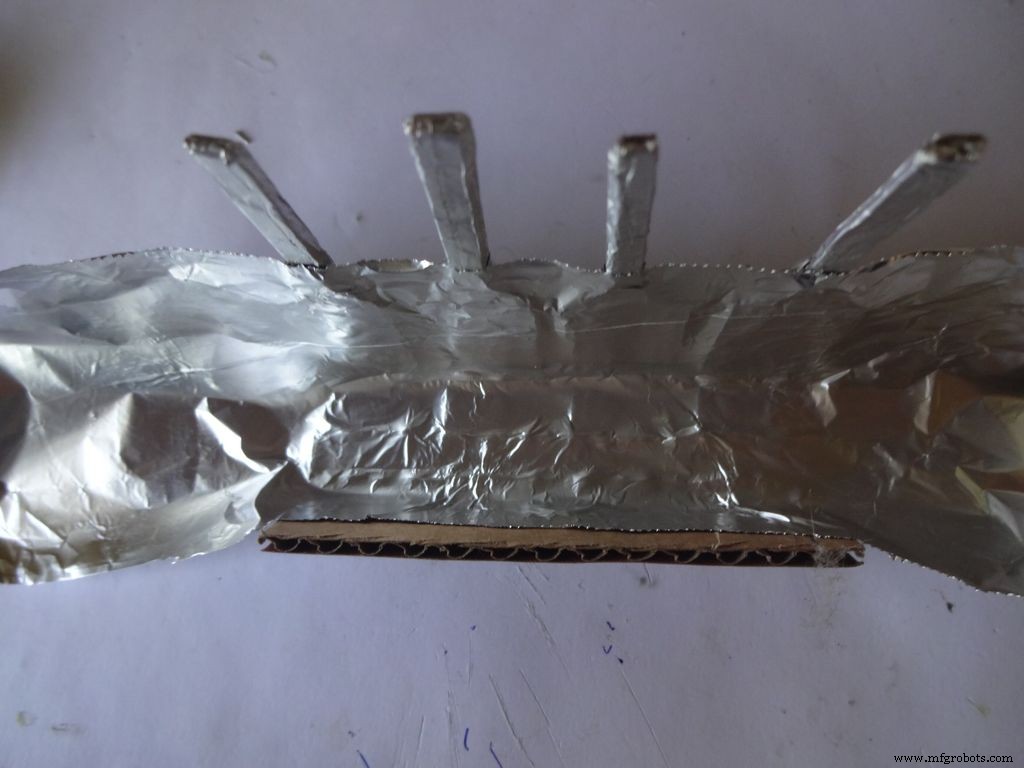
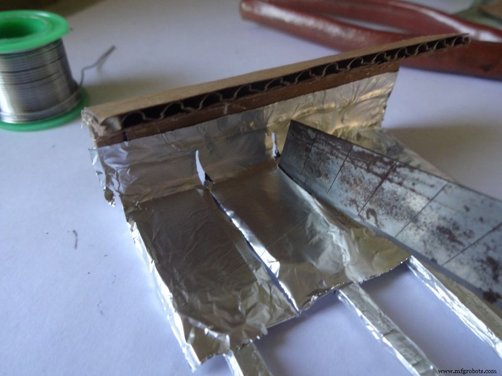
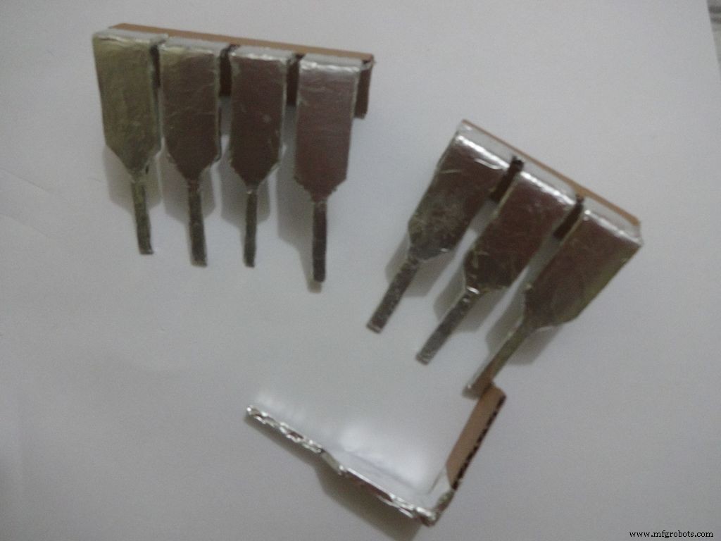

Cut a piece of foil 1x2inches and stick it carefully, fold by fold to the leg ends with some metal-cardboard sticking glue. I used Fevibond.
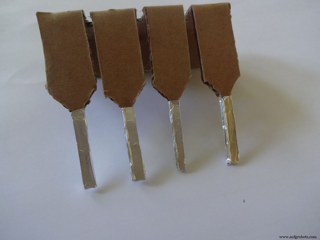
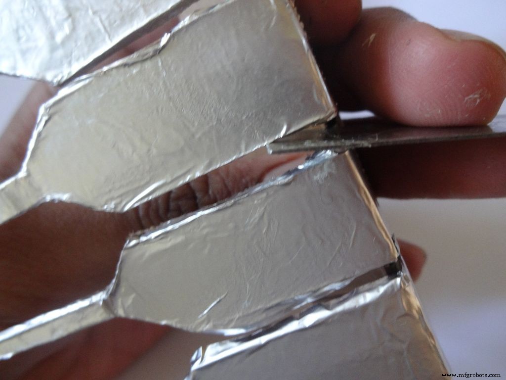
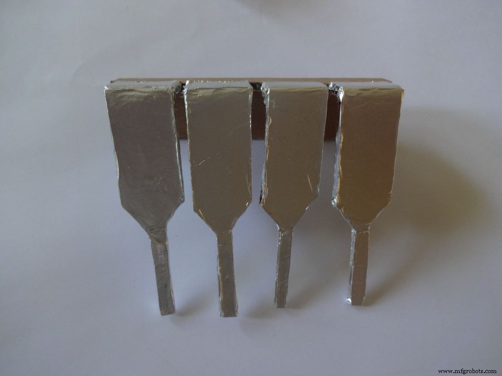
Next stick a patch that covers all the leg tops(as shown), make cuts slowly with a cutter. Do this carefully. The foil tends to tear to the sides. Use something flat to stick the foil in between the legs and give it a good finish.
Now cover it with transparent cello tape, just like you applied the foil, to protect it from sharp objects.
Step 25:The Power Switch
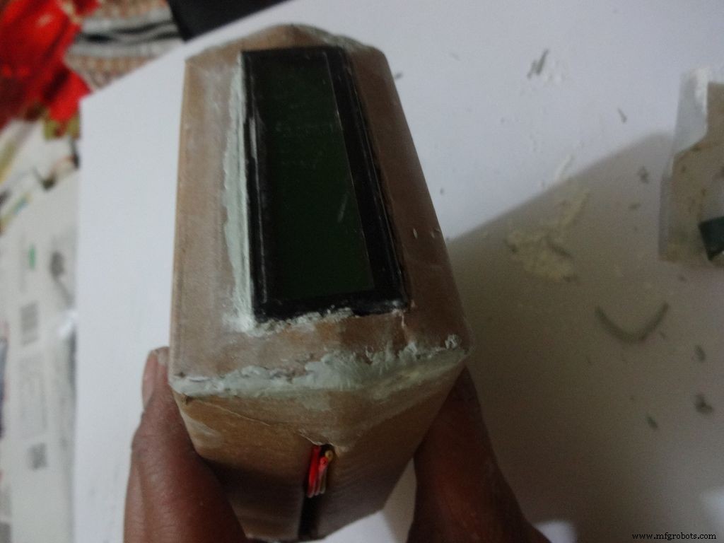
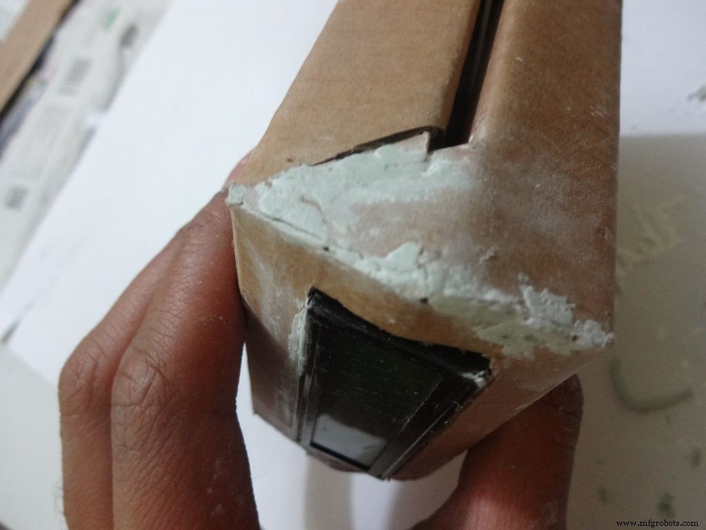
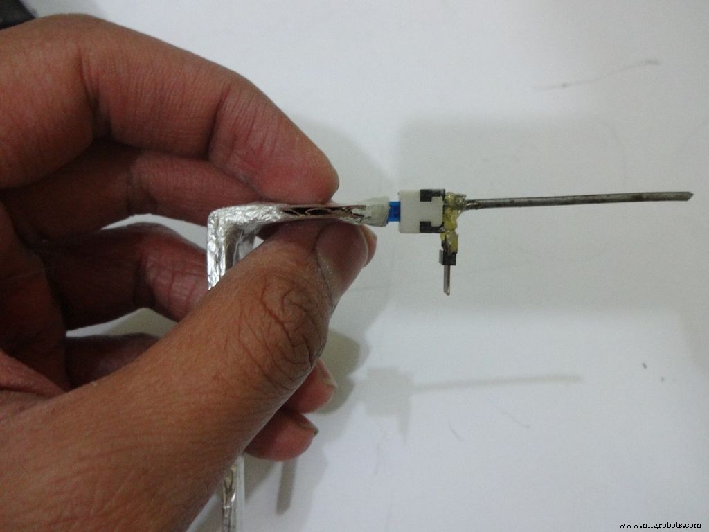
Measure and cut the power switch leg by properly keeping it in place. Temporarily stick the other pins with tape to get the pin1 position right.
Mix the m-seal(epoxy putty sealant, gets very hard when it dries) well. Put it as shown in the images and use powder+flat surface to shape it. Let it dry.
Also fill any gaps left in your case.
Note:We cant use hot glue here as it is rubbery and the switch needs to be stuck with some strong brittle material.
Step 26:Power switch to PCB

After The m-seal dries, place it in to check if everythings alright.
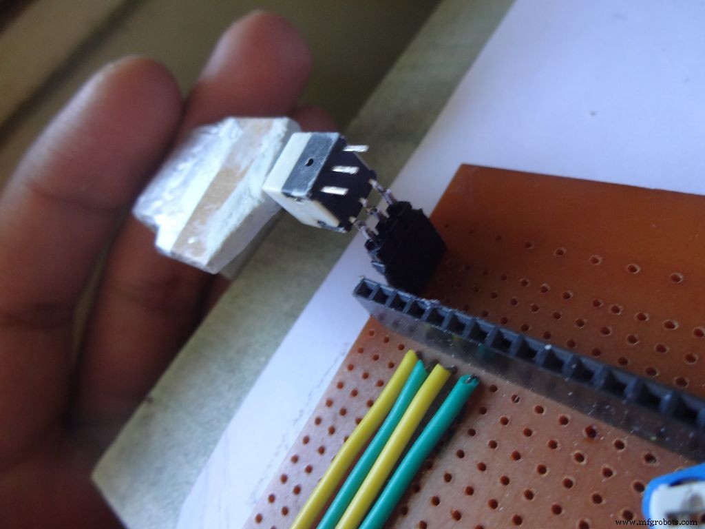
Cut 3pins of female and male headers place it on the PCB such that it aligns with the switch pins. Solder the female part.
Tin the switch leads and the male header pins, join them. See if it fits at the right place.
Try pushing the switch on and off after placing a finger behind the switch for support. We will add a support rod later on.
Connect a side pin of female header(power switch) to Vin. I realised this late and had to undergo lots of trouble.
Secure the header Pin with hot glue.
Step 27:Making the USB Port

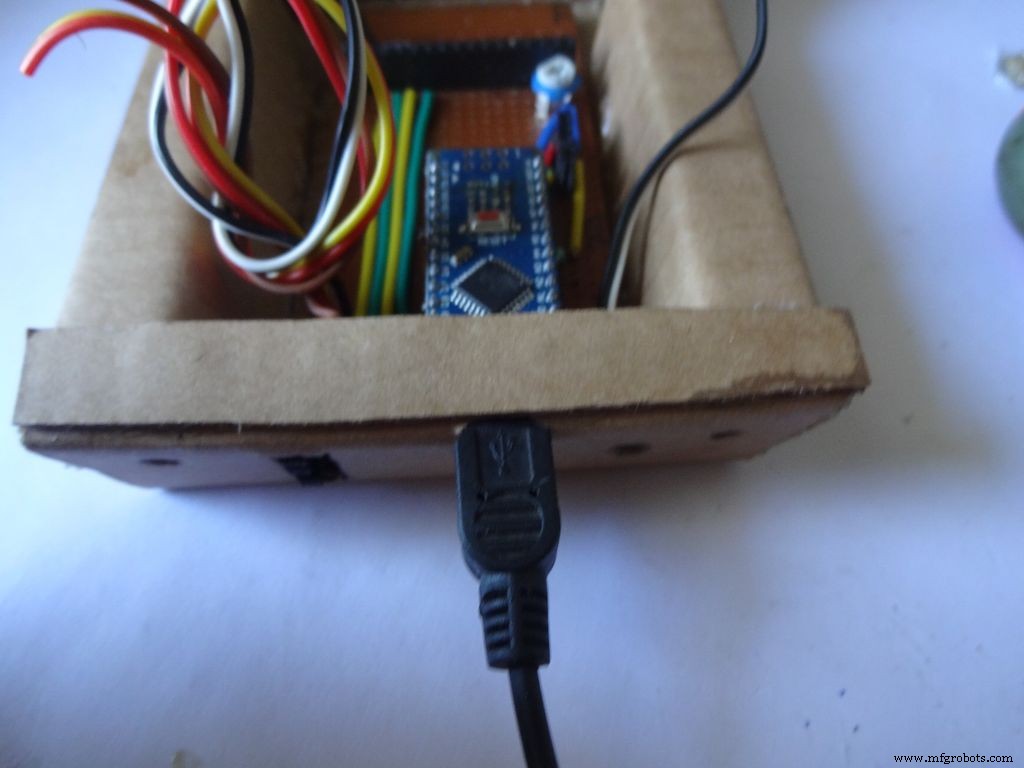
Put the PCB properly in (with Arduino) and cut a rectangle for the mini USB port.
Remove some plastic from the USB cable so that it fits the Arduino properly. Test whether connection is proper.
Step 28:Some other things...

I removed all the LEDs from the Arduino Nano and also the power LED on my RTC module. These consume unnecessary power, which matters if you are operating on a battery.
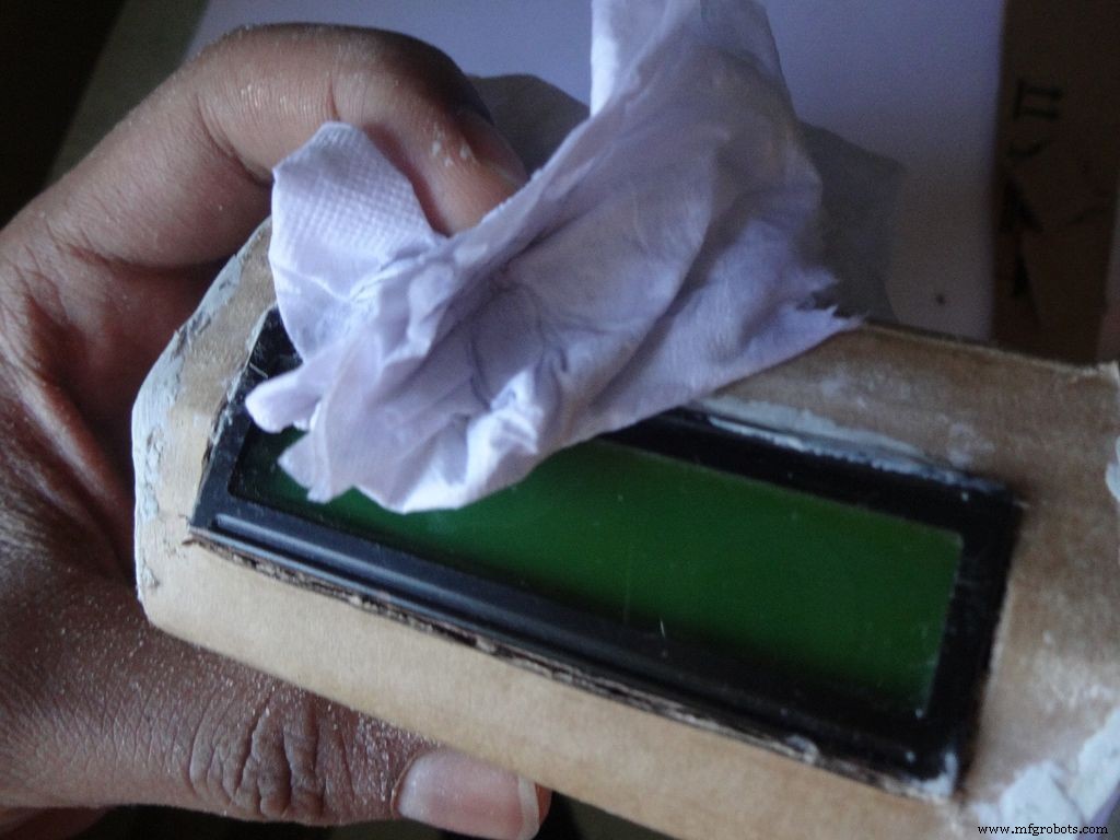
Sand the dried m-seal so that it mixes smoothly with the cardboard. Clean the powder with a wet paper napkin before painting.
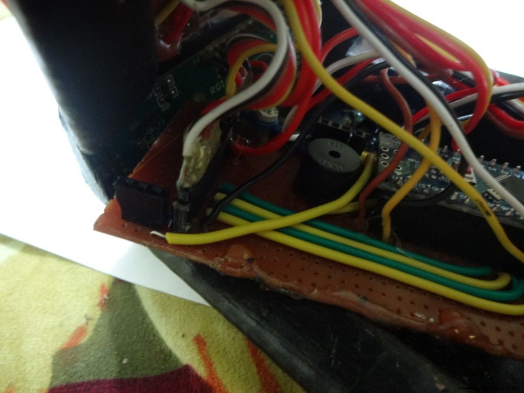
I also added a buzzer which may be used for some functions. Buzzers are sensitive, don't use too much heat while soldering!
Step 29:Time to paint!
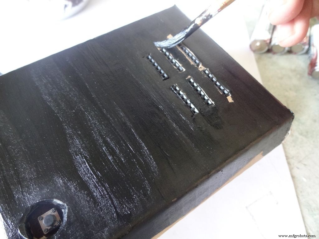
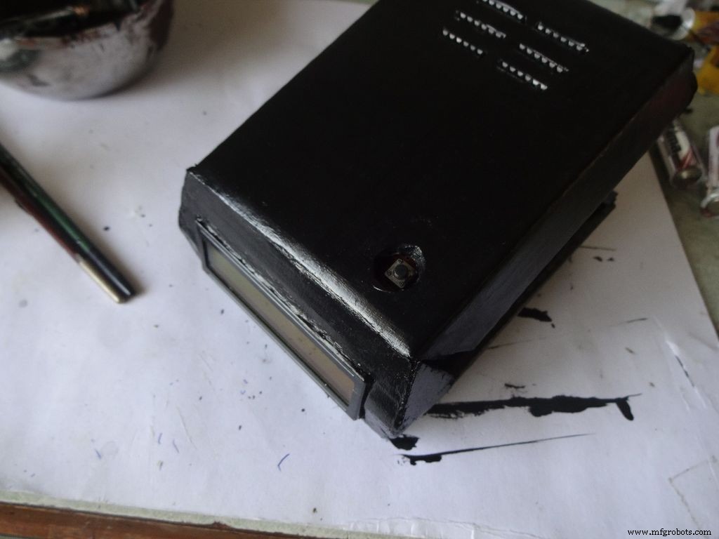
Dont use direct thick paint while painting, this cases brush patterns to appear. Use sufficient water.
Make sure no tiny bubbles are formed. These form when you dab the brush too much.
Dont paint the cover hinge, the paint will restrict it.
This is just a base coat. Another layer of paint will be added while finishing up.
Step 30:Soldering all the wires
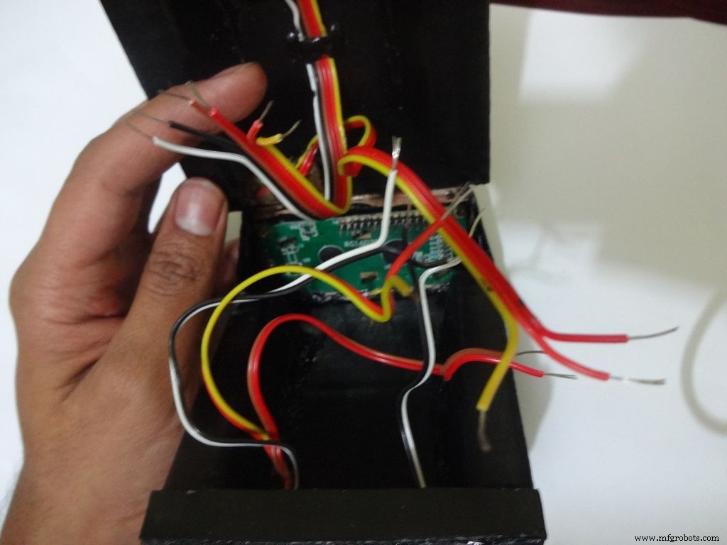
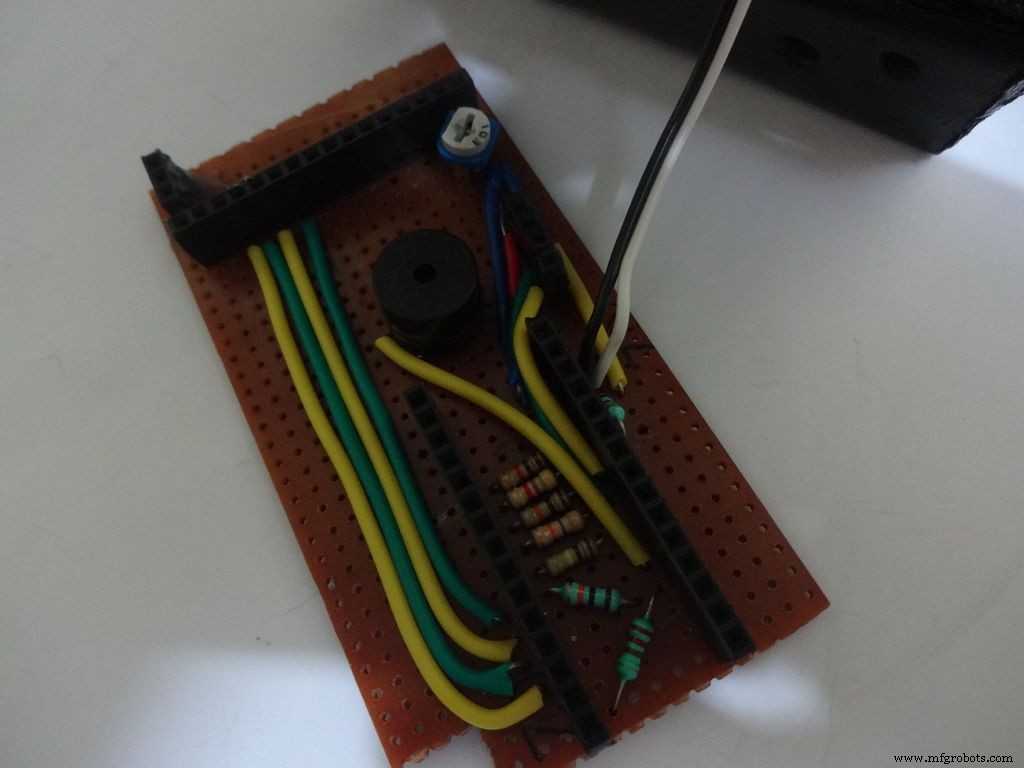
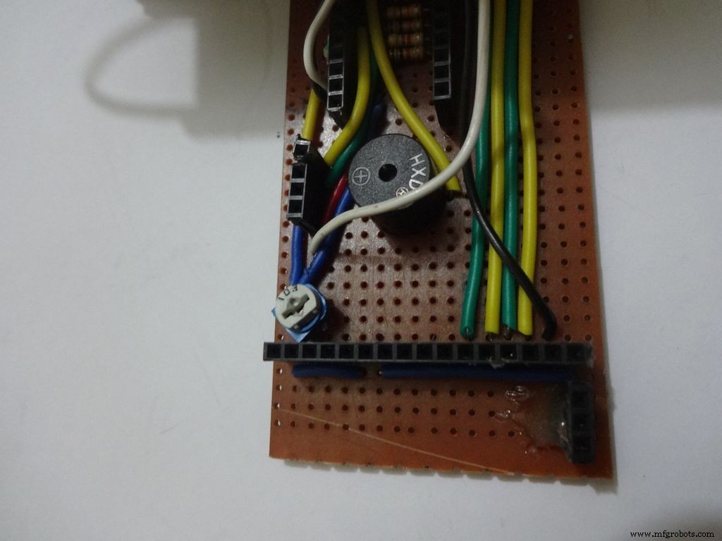
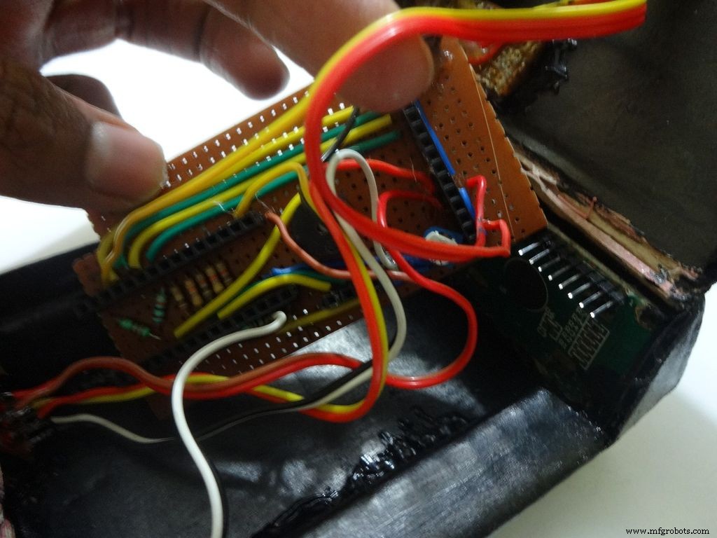
Make sure you refer the circuit design before making any connections.
First connect the reset switch, one end to RST and one end to GND.
Then, the backlight switch. One end to +5V and other end to 'A' or Anode of the backlight LED. Also connect 'K', Cathode to GND.
Next is the RS switch, connect one end to RS and other to pin D1(TX).
And finally the Enable switch. Connect one end to 'E' or Enable and other end to pin D0(RX).
Switches
Where to?
Reset - pushbutton RST and GND Backlight - slide +5V and A RS - slide D1 (TX) and RS Enable - slide D0 (RX) and E
Note:Pins D0 and D1 are connected through switches as keeping them connected sometimes causes problems while using Serial(for debugging).
This completes the base wiring. Apply hot glue after double checking the connections.
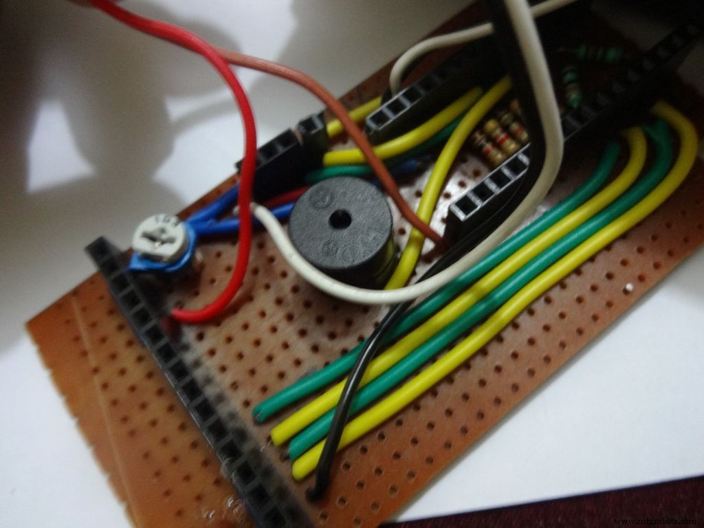
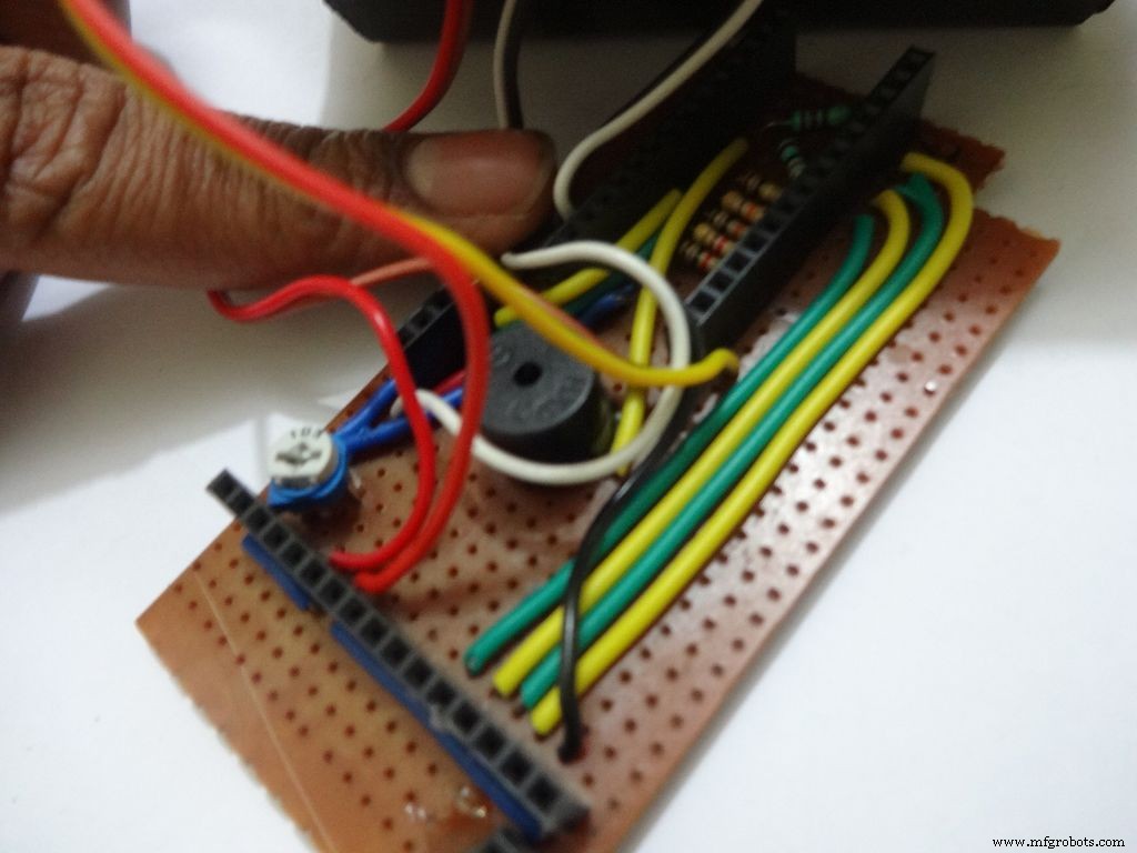
Then connect the 3 wires of mode change button:The 10k pulldown resistor to GND. 220 Ohm resistor to pin D11 and input pin to +5V or VCC
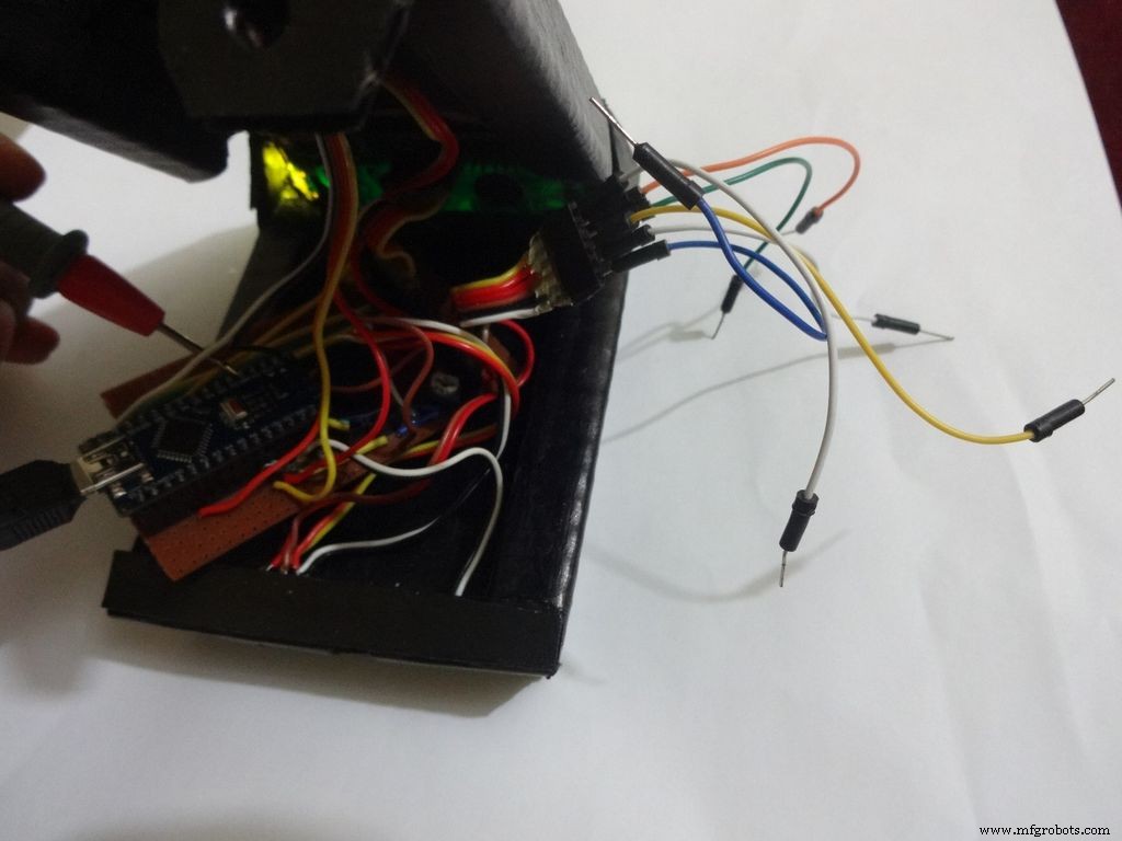
Finally connect the 6 wires from the test slots to their appropriate places(shown in images).
Positive
Negative
Resistance Test A7 GND Capacitance Test A0 GND Diode Test A6 D12
Note:All the +5Vs and GNDs are same and hence connect to most convinient spot.
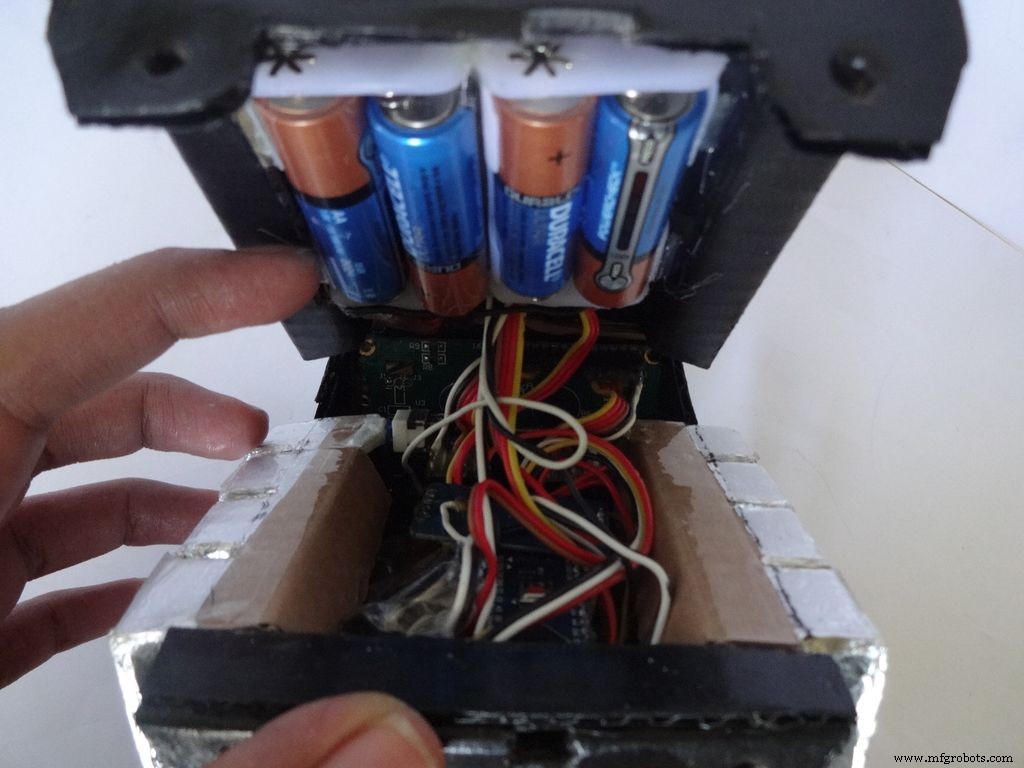
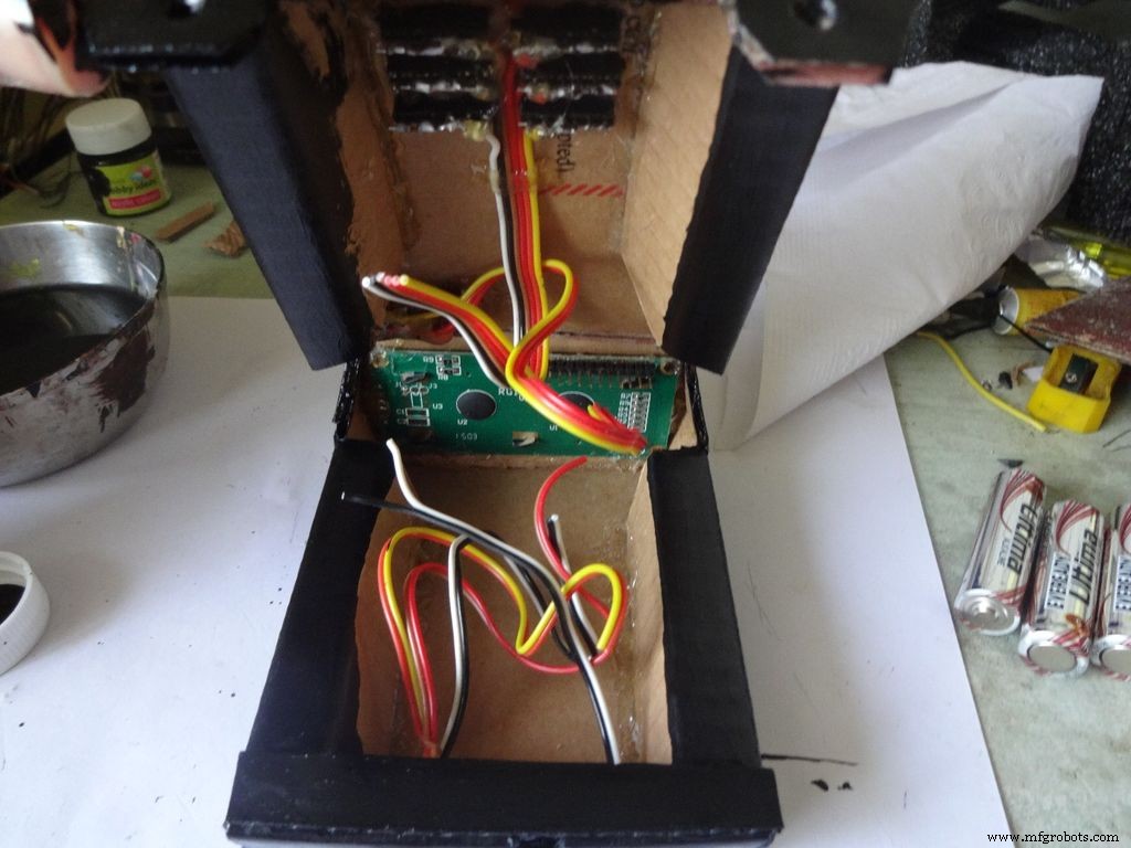
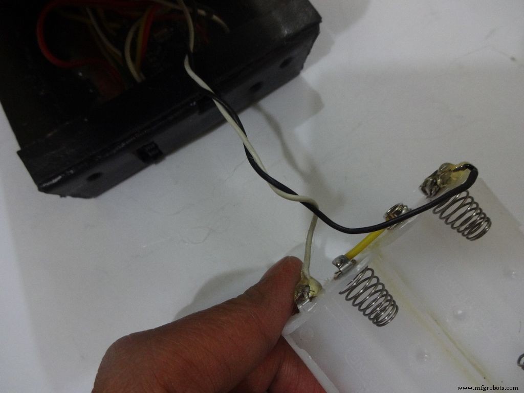
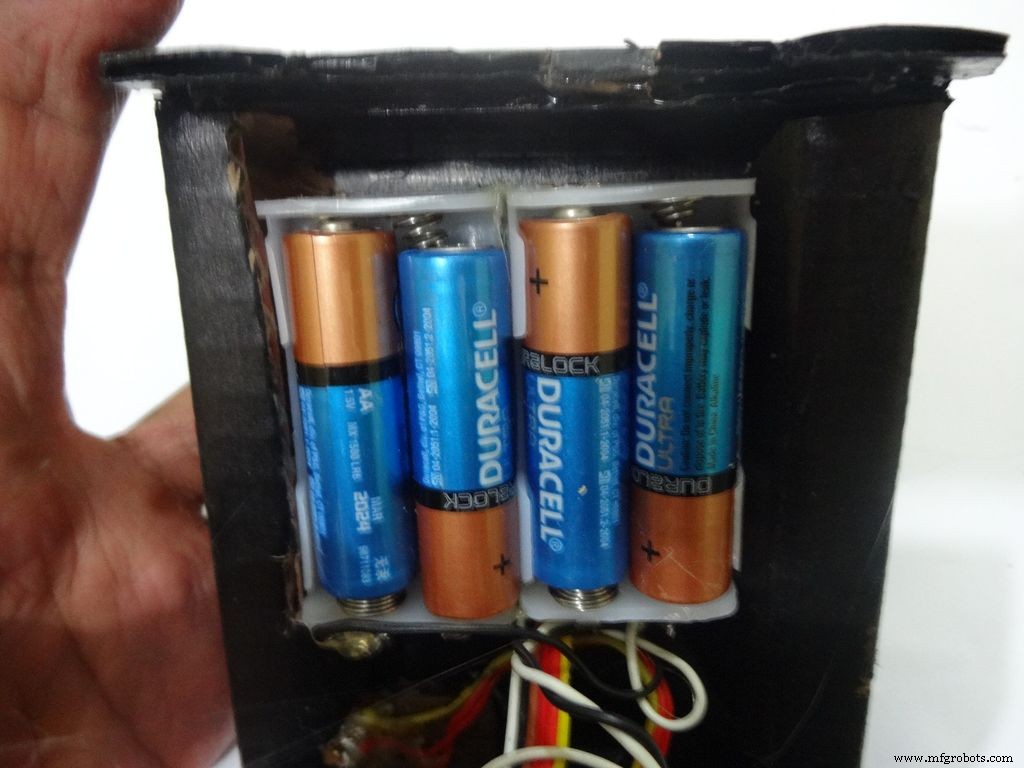
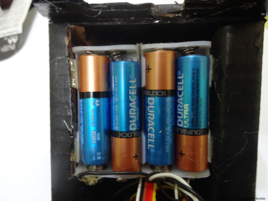
Step 31:Adding the battery case
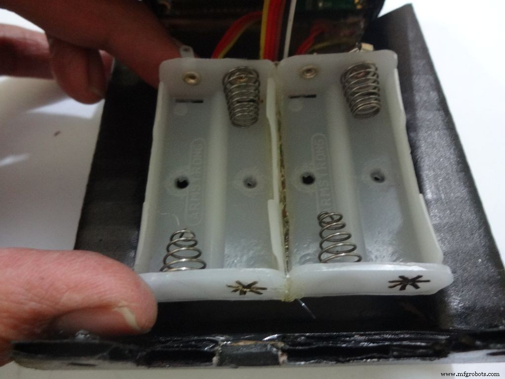
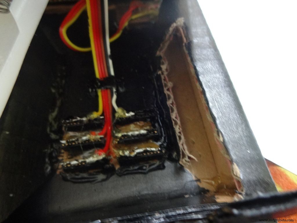
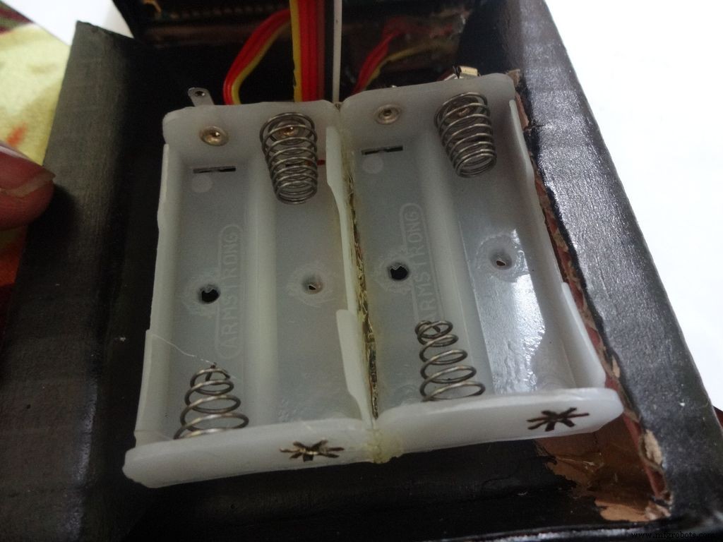

Place the battery case at the top cover, make cuts to place it inside such that the cover can be closed properly.
Solder Wires to the case, strip and tin them. Solder the positive end to the middle pin of power switch and negative end to ground.
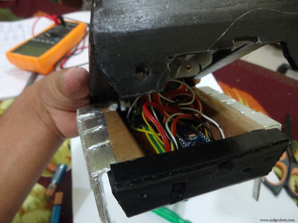
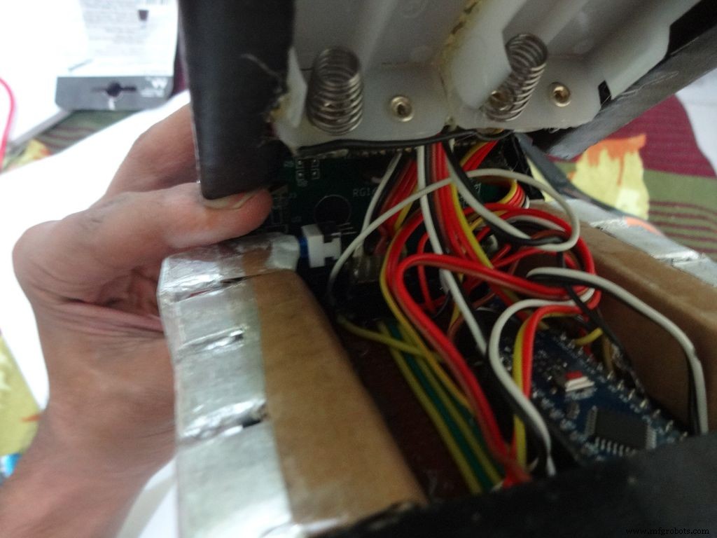
Glue the PCB to the base after making all the connections.
Twist the wires and place them in position. Insert batteries(the case expands a bit on inserting batteries) and glue the case to the cover.
Step 32:Adding the Legs
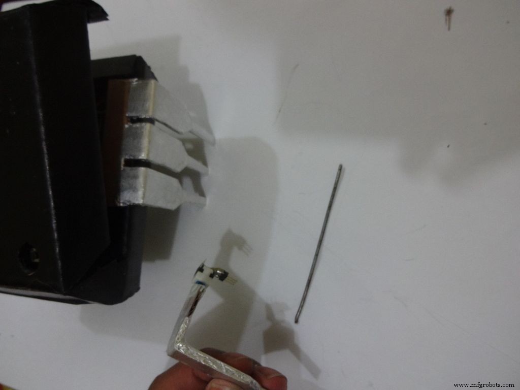
Cut the inner part of legs so that it fits in properly. Stick it it place.
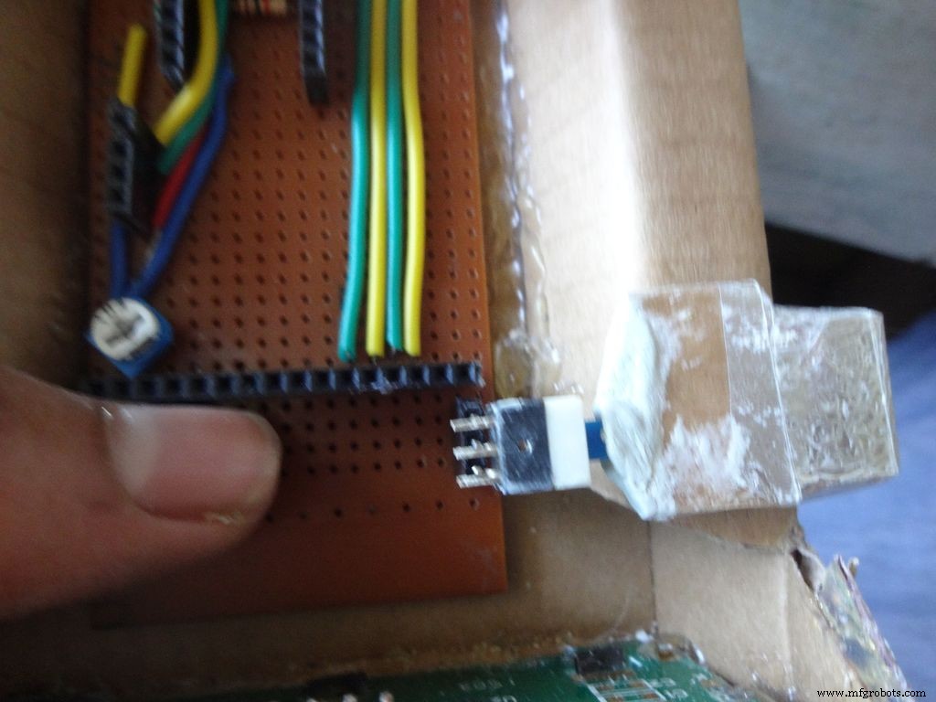
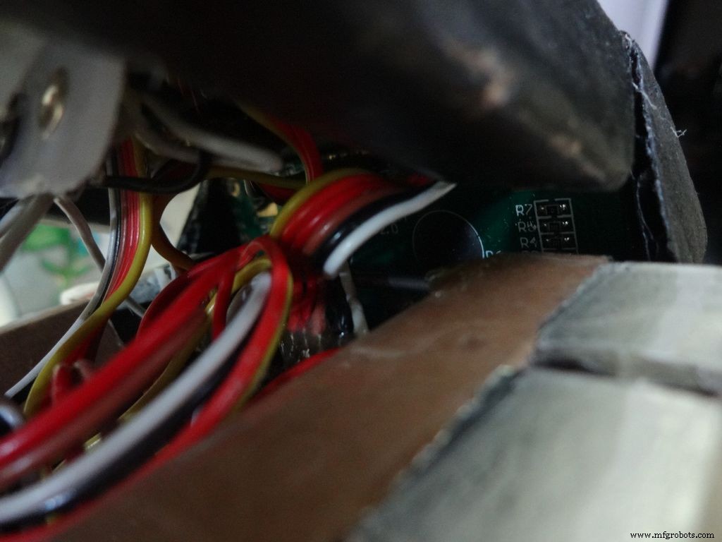
Put the power switch pin in to check if it fits in perfectly. Remove it, add a metal rod, piece of wood or anything strong of proper length that will prevent the switch from moving back. Glue it in place.
Check the switch, it should be turning on/off smoothly.
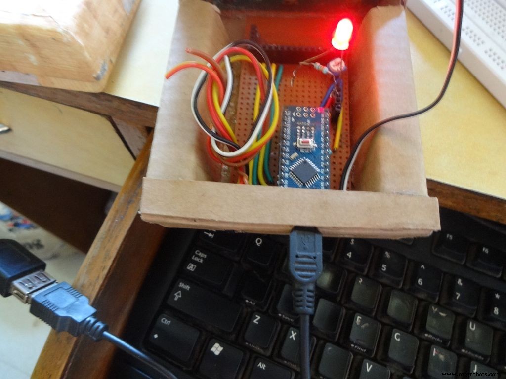
Switch on the IC and test all the functions. If its not working skip to the troubleshooting section.
Step 33:Finishing up!
Use M-seal (or equivalent) to fill any small gaps around the testing area and the mode change button. After drying, sand it well and apply a second layer of paint.
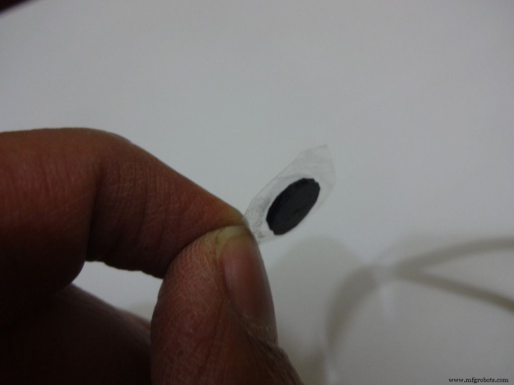
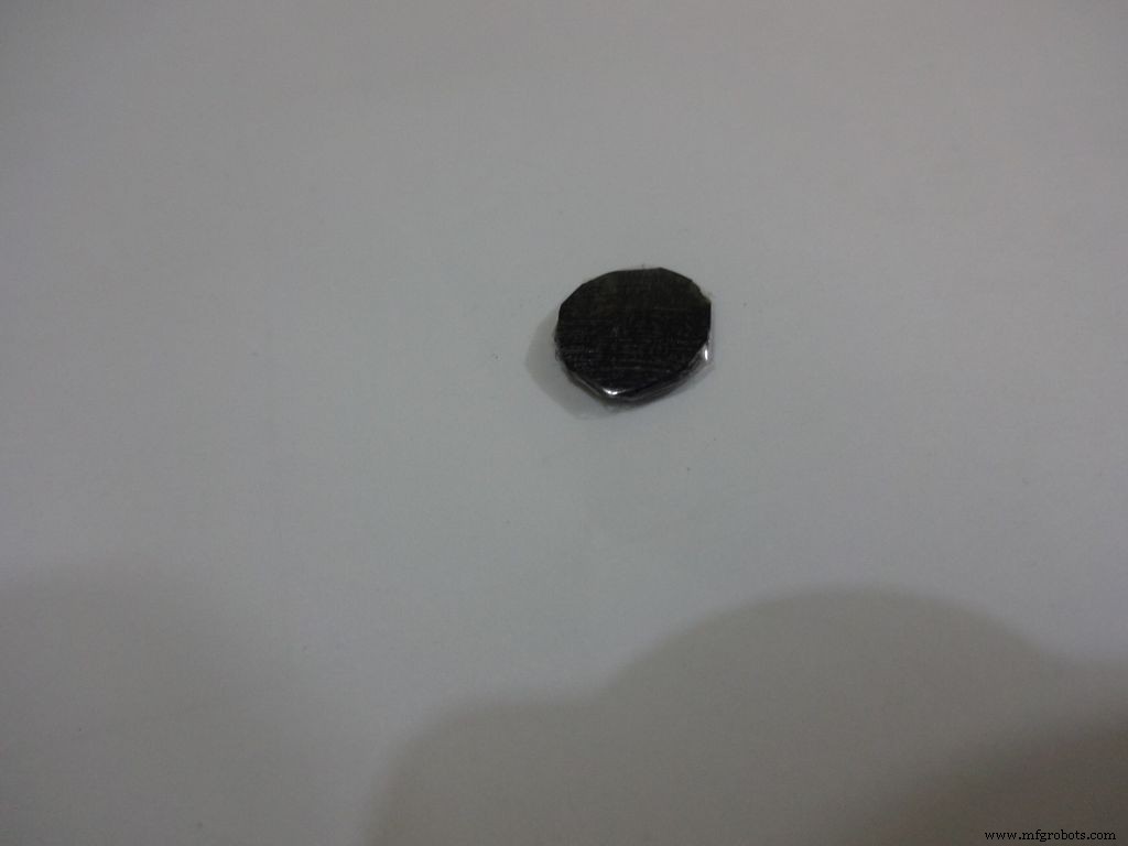
Make the button with a small piece of cardboard, paint it black and cover it with tape(gives a shiny finish). Apply a tiny drop of glue and stick the button in place.
Step 34:Problems and Troubleshooting

Do everything correctly. This is the most boring most of any project and you dont wanna get here just because you soldered the wrong pins!
- Recheck every soldered joint and ensure that it isnt touching the adjacent one. Use the multimeter continuity test for help.
- After cutting component/jumper leads make sure the cut lead doesnt fall underneath the PCB. This may lead to unwanted shorting soldered joints.
- Write down anything you need to remember in a book, don't trust your memory.
- If LCD is not displaying, make sure the contrast is adjusted properly. Also make sure the pin0 and 1 switches are turned ON. Check all the pin connections from LCD to Arduino with continuity test. Use breadboard jumpers wherever your mutimeter cant reach.
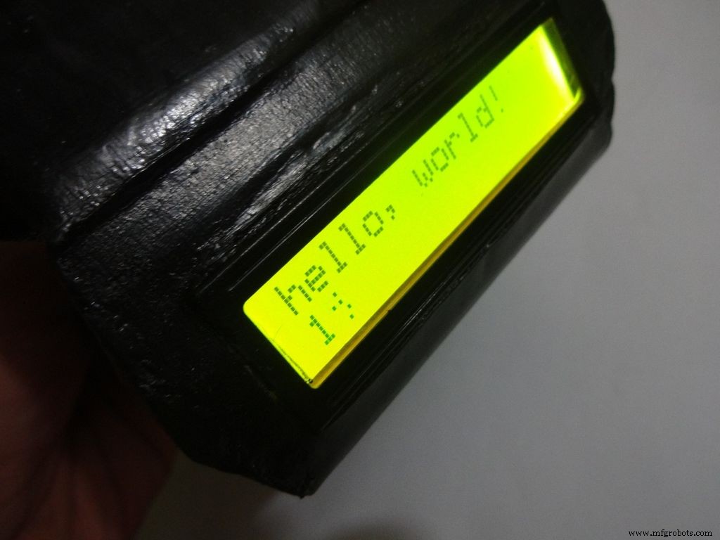
- Upload the hello world LCD program to see if the problem is in the code.
- If a particular function is not working, check its connections and tally it with the code.
- And most importantly, keep your curious pets with their evil minds away from your workspace! :p
Step 35:Things I did, some mistakes I made
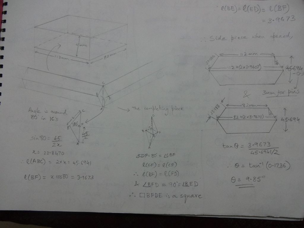

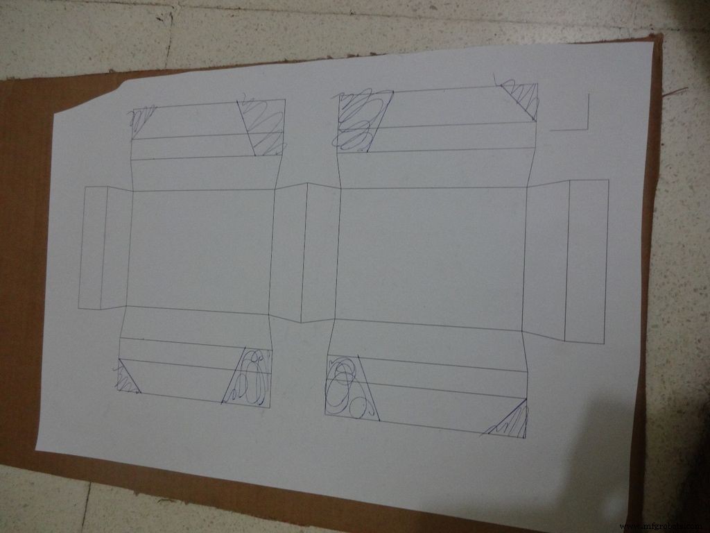
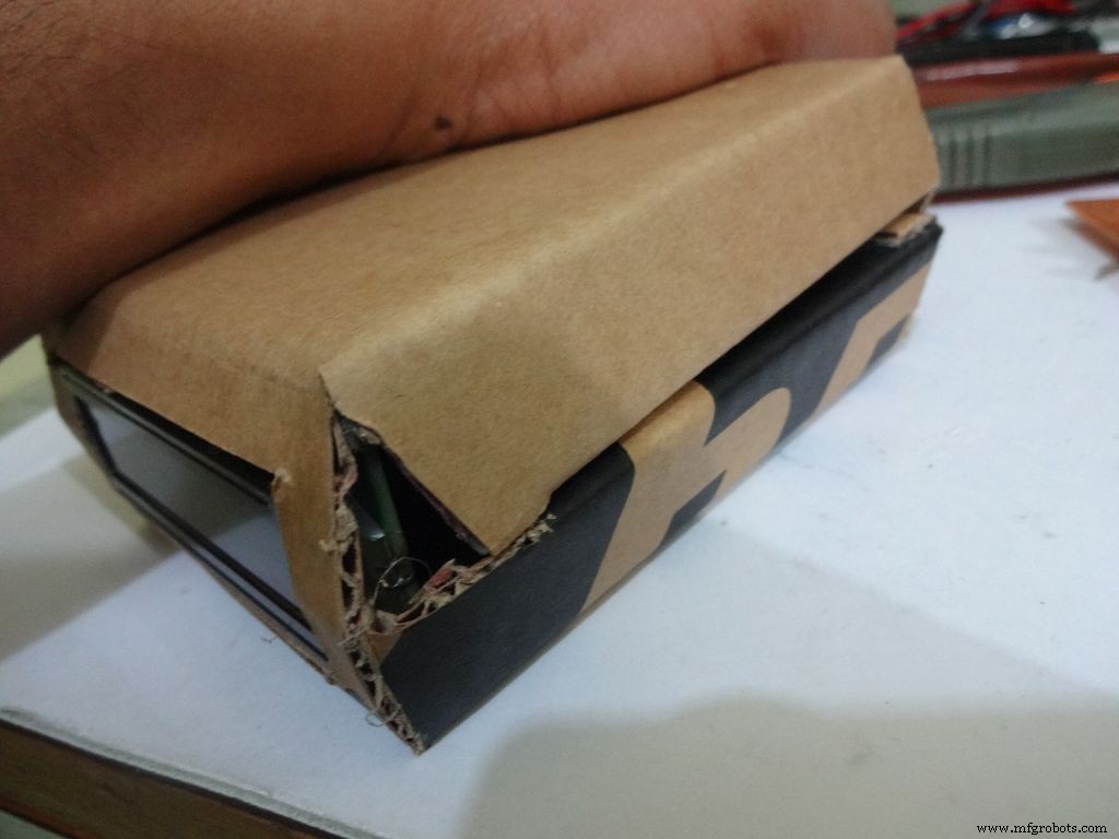
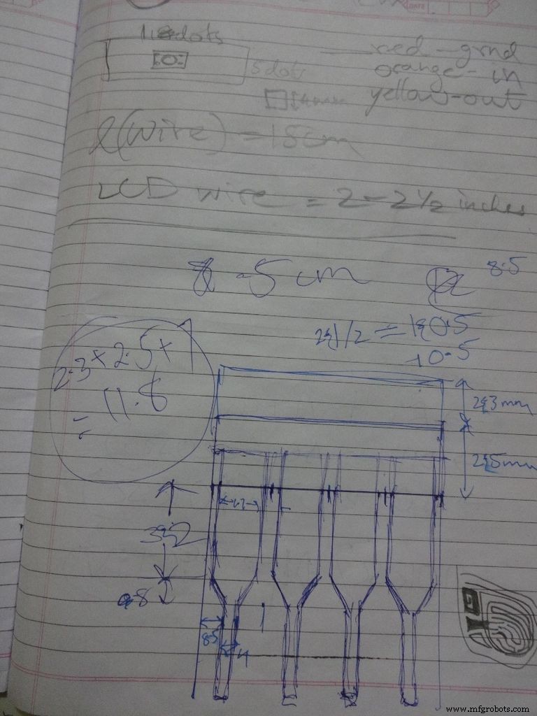
While testing the various circuits and when I had the rough idea of what I want to make, I decided to go with the IC design. I measured actual ICs, took ratios of their lengths, got the angle with some trignometry to be around 80 degrees. Then I decided the inner box length and breadth and built upon it(shown in image). Once the layout was planned, I initially started to draw it accurately on a large size paper. After a bit of a struggle of drawing accurate lines, I realised that this kind of work should be done on a computer! So I learnt CAD basics and succesfully made the layout on it. :) But this layout didnt work out and I had to redo the entire cutting and making of the case.(See images)
While removing the LEDs on the Arduino Nano I used excess pressure to remove a stubborn LED, and ended up removing a PCB pad. Always desolder without forcing/applying pressure on the joints, the pads are delicate and easily come off if you dont stay calm.
When all the solder joints were made and project was about to get finished, in excitement and eagerness, I glued the PCB inside the case before adding the battery case. Had to re-melt the hot glue with a soldering iron (carefully not to melt any wire insulation) and remove the PCB out to solder the battery case wires in. The soldering iron can be cleaned afterwards.
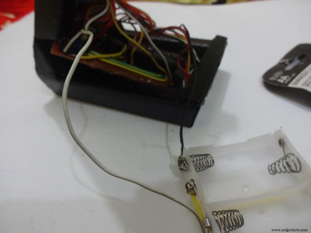
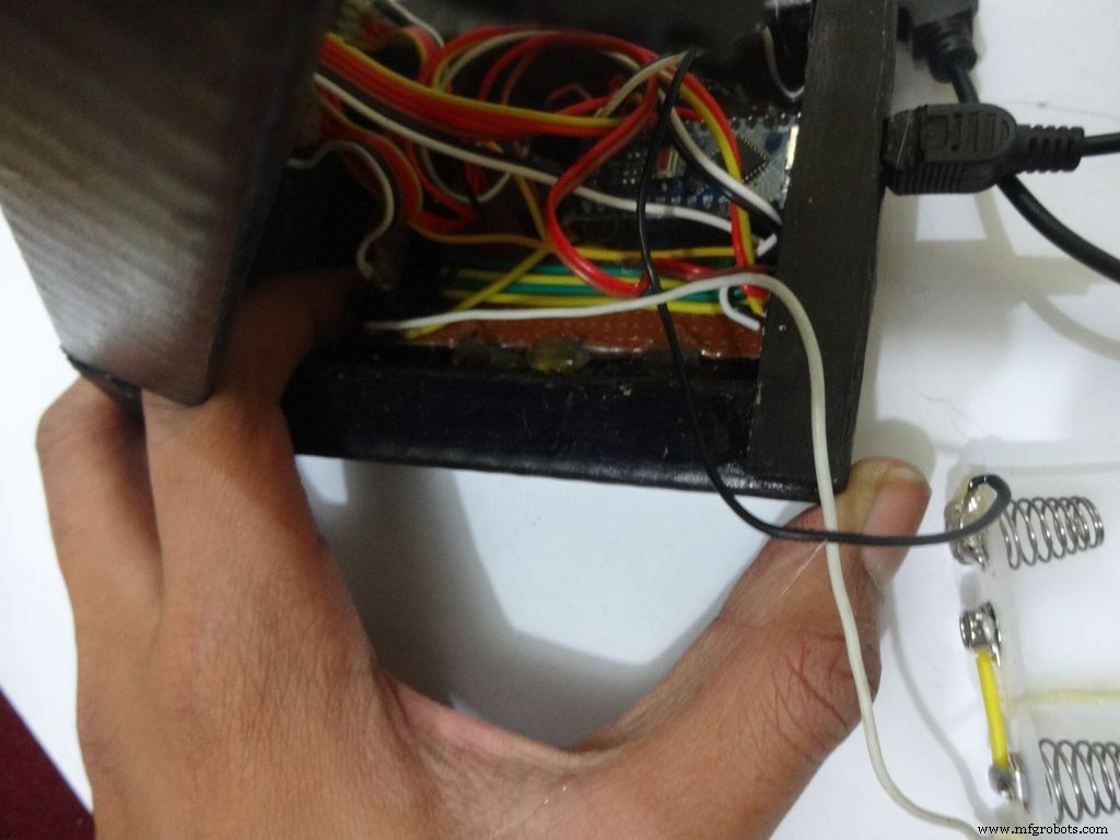
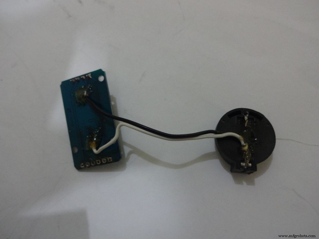
The RTC module battery was coming in way of the batteries while closing and so I separated the battery holder(Warning:desolder only with the battery removed) and added extension wires so that the battery can be placed at the sides where there is space.
All the Layout PDFs, CAD Files and the Main code can be downloaded here:Google Drive
代码
- 代码片段 #1
- 代码片段#2
- 代码片段 #3
- 代码片段 #4
代码片段 #1纯文本
//Analog pin used to find resistanceint Apin=7;//values of r1 to r5float r1=1000;float r2=4700;float r3=10000;float r4=47000;float r5=100000;//pins of r1 to r5int r1_pin=2;int r2_pin=3;int r3_pin=4;int r4_pin=5;int r5_pin=6;float reading=0; //read from analog pin and store herefloat R=0; //calculate unknown and store hereString finalR; //final value to be displayed along with unitsint caseno; //for debugging, stores the case number // we divide the entire range into cases and assign each a number, // total 5 cases // case1 :less than 2850 // case2 :2850 to 7350 // case3 :7350 to 28500 // case4 :28500 to 73500 // case5 :more than 73500#include// needed for converting float to string, //has the String(float,n) function. Explained below.void setup() { Serial.begin(9600);}void loop() { //first we find unknown resistance using 1kOhm resistor //Therefore, disable R2, R3, R4 and R5 digitalWrite(r2_pin, LOW); //turn each pin to LOW before setting it as INPUT pinMode(r2_pin, INPUT); // turning it to INPUT when its HIGH enables the // internal pullup resistor digitalWrite(r3_pin, LOW); pinMode(r3_pin, INPUT); digitalWrite(r4_pin, LOW); pinMode(r4_pin, INPUT); digitalWrite(r5_pin, LOW); pinMode(r5_pin, INPUT); pinMode(r1_pin, OUTPUT); digitalWrite(r1_pin, HIGH); //read and calculate resistance reading=analogRead(Apin); R=(reading*r1)/(1023-reading); // if value <2850, finalR =value(using 1kOhm) if(R<2850){ caseno=1; if(R<1000){ //if value less than 1000 use "Ohm" not "kOhm" finalR =String(R,2) + "Ohm"; //String(float,n) Converting float to string //with n digits after decimal // attach "Ohm" after value to the string, //'+' joins two strings here } else{ //use "kOhm R=R/1000; finalR =String(R,2) + "kOhm"; } } //if value between 2850 and 7350 , use value obtained by 4.7kOhm else if(R>=2850 &&R<7350){ caseno=2; digitalWrite(r1_pin, LOW); //Enable only 4.7kOhm pinMode(r1_pin, INPUT); digitalWrite(r3_pin, LOW); pinMode(r3_pin, INPUT); digitalWrite(r4_pin, LOW); pinMode(r4_pin, INPUT); digitalWrite(r5_pin, LOW); pinMode(r5_pin, INPUT); pinMode(r2_pin, OUTPUT); digitalWrite(r2_pin, HIGH); reading=analogRead(Apin); R=(reading*r2)/(1023-reading)/1000; finalR =String(R,2) + "kOhm"; } //if value between 7350 and 28500, use value obtained by 10kOhm else if(R>=7350 &&R<28500){ caseno=3; digitalWrite(r1_pin, LOW); pinMode(r1_pin, INPUT); digitalWrite(r2_pin, LOW); pinMode(r2_pin, INPUT); digitalWrite(r4_pin, LOW); pinMode(r4_pin, INPUT); digitalWrite(r5_pin, LOW); pinMode(r5 _pin, INPUT); pinMode(r3_pin, OUTPUT); digitalWrite(r3_pin, HIGH); reading=analogRead(Apin); R=(reading*r3)/(1023-reading)/1000; finalR=String(R,2) + "kOhm"; } //if value between 28500 and 73500, use value obtained by 47kOhm else if(R>=28500 &&R<73500){ caseno=4; digitalWrite(r1_pin, LOW); pinMode(r1_pin, INPUT); digitalWrite(r2_pin, LOW); pinMode(r2_pin, INPUT); digitalWrite(r3_pin, LOW); pinMode(r3_pin, INPUT); digitalWrite(r5_pin, LOW); pinMode(r5_pin, INPUT); pinMode(r4_pin, OUTPUT); digitalWrite(r4_pin, HIGH); reading=analogRead(Apin); R=(reading*r4)/(1023-reading)/1000; finalR =String(R,2) + "kOhm"; } //if value more than 73500, use value obtained by 100kOhm else if(R>=73500){ caseno=5; digitalWrite(r1_pin, LOW); pinMode(r1_pin, INPUT); digitalWrite(r2_pin, LOW); pinMode(r2_pin, INPUT); digitalWrite(r3_pin, LOW); pinMode(r3_pin, INPUT); digitalWrite(r4_pin, LOW); pinMode(r4_pin, INPUT); pinMode(r5_pin, OUTPUT); digitalWrite(r5_pin, HIGH); reading=analogRead(Apin); R=(reading*r5)/(1023-reading)/1000; finalR =String(R,2) + "kOhm"; } Serial.println(finalR); //printing the final string with units Serial.println(" ");延迟(1000); }
代码片段#2纯文本
/* RCTiming_capacitance_meter * code concept taken from Paul Badger 2008 * * The capacitor's voltage at one time constant is defined as * 63.2% of the charging voltage. * i.e, A Capacitor is filled to 63.2% of its total capacity in * 1 Time Constant */ int analogPin=0; // analog pin for measuring capacitor voltage int chargePin=7; // pin to charge the capacitor - connected to // one end of the charging resistor int dischargePin=12; // pin to discharge the capacitor, // same used for diode test(checkPin1) float resistorValue=10000.0; // We use 10kOhm resistor unsigned long startTime; unsigned long elapsedTime; float microFarads; // floating point variable to preserve precision float nanoFarads;void setup(){ pinMode(chargePin, OUTPUT); // set chargePin to output digitalWrite(chargePin, LOW); Serial.begin(9600); // initialize serial transmission for debugging}void loop(){ digitalWrite(chargePin, HIGH); // set chargePin HIGH and capacitor charging startTime =millis(); while(analogRead(analogPin) <648){ // just wait and do nothing till 648 // 647 is 63.2% of 1023, // which corresponds to full-scale voltage } elapsedTime=millis() - startTime; // convert milliseconds to seconds ( 10^-3 ) // and Farads to microFarads ( 10^6 ), net 10^3 (1000) microFarads =((float)elapsedTime / resistorValue) * 1000; // (float) converts "unsigned long" elapsed time to float Serial.print(elapsedTime); // print the value to serial port Serial.print(" mS "); // print units if (microFarads> 1){ Serial.print((long)microFarads); // print the value to serial port Serial.println(" microFarads"); // print units } else { // if value is smaller than one microFarad, convert to nanoFarads (10^-9 Farad). nanoFarads =microFarads * 1000.0; // multiply by 1000 to convert to nanoFarads (10^-9 Farads) Serial.print((long)nanoFarads); // print the value to serial port Serial.println(" nanoFarads"); // print units } /* dicharge the capacitor */ digitalWrite(chargePin, LOW); // set charge pin to LOW pinMode(dischargePin, OUTPUT); // set discharge pin to output digitalWrite(dischargePin, LOW); // set discharge pin LOW while(analogRead(analogPin)> 0){ // wait until capacitor is completely discharged } pinMode(dischargePin, INPUT); // set discharge pin back to input} 代码片段 #3纯文本
String state ="null"; //prints "null" for reverse bias or nothing connectedint checkPin1 =12;int checkPin2 =6;void setup() { Serial.begin(9600);}void loop() {pinMode(checkPin1, OUTPUT); digitalWrite(checkPin1, LOW); //pin 11 is set to low//analog read is normally pulled up by the 10k resistor, so null reading is 1023//In forward bias, the analog pin gets connected to checkPin1, which is LOW. So reading less than 1023//Practically a small current flows in reverse bias as well, so we take 700 to differentiate if(analogRead(checkPin2)<700){ state="forward"; } Serial.println(state); Serial.println(analogRead(checkPin2)); state ="null";延迟(500);} 代码片段 #4纯文本
// Date and time functions using a DS1307 RTC connected via I2C and Wire lib#include #include RTC_DS1307 rtc;//creating "rtc" object of RTC_DS1307, objects are used to access functions //more on objects and classes:https://www.youtube.com/watch?v=ABRP_5RYhqUchar daysOfTheWeek[7][12] ={"Sunday", "Monday", "Tuesday", "Wednesday", "Thursday", "Friday", "Saturday"};void setup () { Serial.begin(9600); rtc.begin(); // following line sets the RTC to the date &time this sketch was compiled // rtc.adjust(DateTime(F(__DATE__), F(__TIME__))); // This line sets the RTC with an explicit date &time, for example to set // January 21, 2014 at 3am you would call:// rtc.adjust(DateTime(2014, 1, 21, 3, 0, 0));}void loop () { DateTime now =rtc.now(); Serial.print(now.year()); Serial.print('/'); Serial.print(now.month()); Serial.print('/'); Serial.print(now.day()); Serial.print(" ("); Serial.print(daysOfTheWeek[now.dayOfTheWeek()]); Serial.print(") "); Serial.print(now.hour()); Serial.print(':'); Serial.print(now.minute()); Serial.print(':'); Serial.print(now.second()); Serial.println(); Serial.println(); delay(1000);} Github
https://github.com/adafruit/RTClibhttps://github.com/adafruit/RTClib示意图
Main_Schematic.fzz制造工艺