

Arduino 和 HC-12 远程无线通信模块
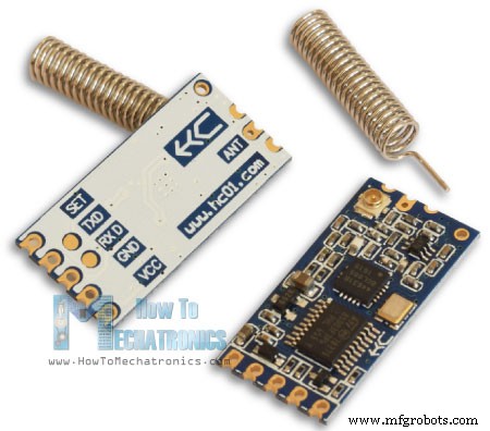
在本 Arduino 教程中,我们将学习如何使用 HC-12 无线串行通信模块,该模块能够在多个 Arduino 板之间进行远距离无线通信,距离可达 1.8 公里。您可以观看以下视频或阅读下面的书面教程了解更多详情。
在本教程中,我制作了两个基本示例来解释如何连接 HC-12 模块并在两个 Arduino 之间进行基本通信,以及在第一个 Arduino 上使用加速度计传感器的另一个示例,我在第二个 Arduino 上无线控制步进器的位置阿杜诺。
首先我们来详细了解一下HC-12无线串口通讯模块。以下是一些规范:
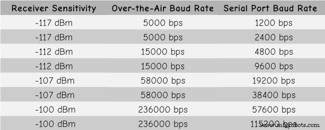
这些值实际上取决于所选的串行和无线波特率,如表中所示。
HC-12 模块有一个微控制器,实际上不必由用户编程。为了配置模块,我们只需使用 AT 命令,这些命令可以从 Arduino、PC 或任何其他使用串行端口的微控制器发送。进入 AT 指令模式只需要将模块的“Set”引脚设置为逻辑低电平即可。
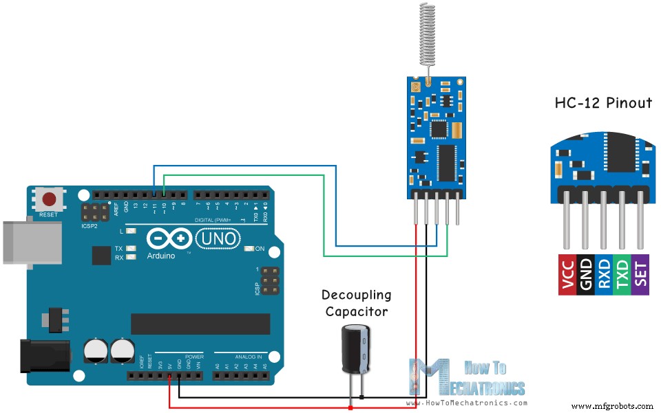
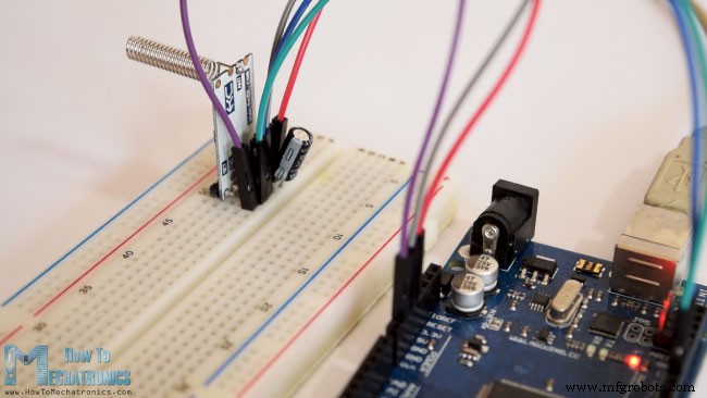
现在让我们将 HC-12 模块连接到 Arduino 并制作第一个示例。这是电路原理图。模块的工作电压为 3.2V 到 5.5V,为了更稳定的工作建议使用去耦电容和外部电源。但是,我在本教程中的所有三个示例中都使用了 PC USB 作为电源,并且没有任何问题。
我将第一个模块连接到 Arduino UNO,将第二个模块连接到 Arduino MEGA,当然,您可以使用任何您想要的板。
您可以从以下链接获取本 Arduino 教程所需的组件:
这是第一个示例的 Arduino 代码,两个模块之间使用串行监视器进行基本通信。
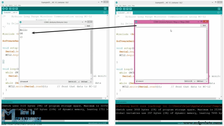
两个 Arduino 使用相同的代码。我们可以将两个 Arduino 连接在两台不同的计算机上,也可以使用一台计算机。
在这种情况下,一旦我们将第一个 Arduino 连接到计算机,我们需要选择型号和 COM 端口并将代码上传到 Arduino。然后我们连接第二个 Arduino,我们必须再次启动 Arduino IDE,以便能够选择我们的第二个 Arduino 连接到的另一个 COM 端口,然后上传相同的代码。
因此,一旦我们运行了两个 Arduino IDE,我们就可以启动串行监视器并测试通信是否正常。我们在串行监视器中键入的任何内容都将从一个 Arduino 发送到另一个 Arduino。
代码的工作原理: 因此,一旦我们在串行监视器中键入内容并单击“发送”按钮,在第一个 Arduino 上,带有 Serial.available() 函数的 while 循环将变为真,并且使用 HC12.write() 函数,我们将从串行监视器连接到 HC-12 模块。该模块会将数据无线传输到第二个 HC-12 模块,因此在第二个 Arduino 中,带有 HC12.available() 函数的 while 循环将变为真,并使用 Serial.write() 函数将数据发送到串行监视器。
我们可以使用相同的代码发送 AT 命令和配置模块参数。我们所要做的就是将模块的“Set”引脚连接到地或Arduino的任何数字引脚,并将引脚设置为低逻辑电平。
为了测试我们是否成功进入模式,在串口监视器中我们可以输入“AT”,我们应该得到一个响应消息“OK”。 AT 命令共有 12 个,用于更改波特率、通道、发射功率等各种参数。例如,如果我们输入“AT+B38400”,则模块的波特率将设置为38400.
1. AT - 测试命令。
示例:向模块发送“AT”,模块返回“OK”。
2. AT+Bxxxx – 更改串口波特率。
可用波特率:1200 bps、2400 bps、4800 bps、9600 bps、19200 bps、38400 bps、57600 bps 和 115200 bps。默认值:9600 bps。
例:发送“AT+B38400”给模块,模块返回“OK+B19200”。
3. AT+Cxxxx – 更改无线通讯频道,从001改为100。
默认值:001 频道,工作频率为 433.4MHz。每个下一个频道都高 400KHz。
示例:如果我们要将模块设置为通道 006,我们需要向模块发送“AT+C006”命令,模块将返回“OK+C006”。新的工作频率为 435.4MHz。
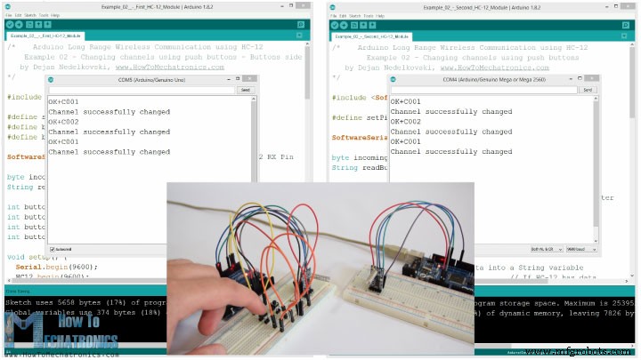
现在让我们移动第二个例子。在这里,我们将使用两个按钮来选择不同的通信通道,并查看存储传入数据的不同方法。
注意:两个 HC-12 模块的“设置”引脚连接到两个 Arduino 的引脚 6,第一个 Arduino 上的两个按钮连接到引脚 4 和 3。
第一个Arduino代码:
第二个Arduino代码:
代码说明:
因此,首先我们需要定义引脚并将“Set”引脚设置为高逻辑电平,以便模块在正常透明模式下工作。在第一个 while 循环中,我们将传入的数据存储到一个 String 变量中,这样我们可以更好地处理它。
传入的数据总是一次一个字节,例如,如果我们从第二个 Arduino 发送字符串“Test123”,这个 while 循环将执行 7 次迭代。每次迭代,使用 HC12.read() 函数,我们将读取每个传入的字节或字符,并将其添加到名为“readBuffer”的字符串变量中。
接下来让我们看看如何使用第一个按钮更改通信渠道。因此,如果我们按下第一个按钮,使用 HC12.print() 函数,我们会将字符串“AT+C001”发送到 HC-12 模块或第二个 Arduino。
当第二个 Arduino 接收到该字符串时,我们将 HC-12 模块设置为 AT 命令模式,然后写入相同的字符串“AT+C001”,将模块设置为通讯通道号。
我们使用下一个 while 循环来打印来自 HC-12 模块的响应消息是否已成功更改频道。
回到第一个 Arduino,我们执行相同的过程,将 AT 命令发送到第一个 HC-12 模块。以同样的方式,使用第二个按钮,我们设置了第二个通信通道。因此,使用这种方法,我们可以随时选择与哪个 HC-12 模块进行通信。
最后,checkATCommand()自定义函数,通过检查字符串是否以“AT”开头来检查接收到的消息是否为AT命令。如果是,则模块进入AT命令模式并执行命令。
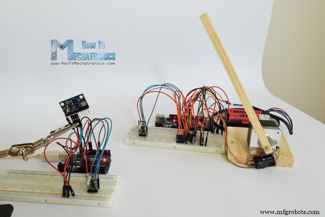
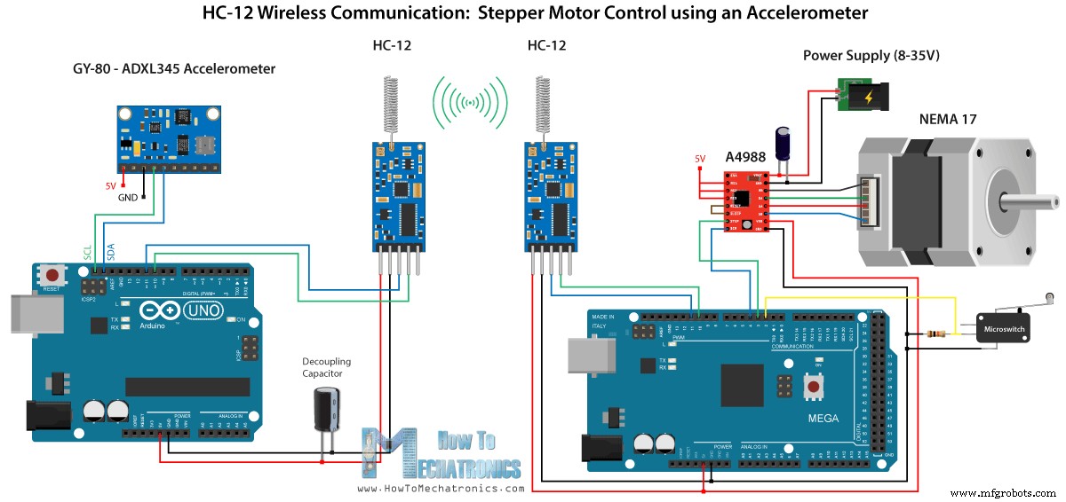
现在让我们看第三个例子。这里我们使用第一个 Arduino 上的加速度计模块来控制第二个 Arduino 上的步进电机的位置。
该电路还包含一个微动开关,用于查找步进电机在 0 度时的初始位置。
您可以从以下链接获取此示例所需的组件:
注意这里我已经有关于如何连接和使用加速度计和步进电机的详细教程,所以对于这个例子我将只解释代码的HC-12部分。
第一个 Arduino - 发射器代码:
第二个 Arduino - 接收器代码:
代码说明:
因此,首先我们在设置部分定义引脚并初始化模块。然后我们读取加速度计的 X 和 Y 轴的值,并将它们映射到 0 到 180 度的值。来自加速度计的值有时会不稳定或抖动,因此为了平滑结果,我使用了一百个读数的平均值。
为了进一步平滑,我将发送新的角度值,前提是它与之前的值相差 2。
这里注意发送角度到HC-12模块时,我也是在前面发送字符“s”,然后发送字符“e”,这将有助于我在第二个Arduino接收数据时。
在第二个 Arduino 中,我们等到开始标记“s”到来,然后我们读取角度值,直到结束标记“e”到来。这样我们就可以确定我们只会收到角度的值。
然后我们将该值转换为整数,并将该值从 0 映射到 1600 步,这对应于 A4988 步进驱动器上选择的第 16 步分辨率。然后我们将步进电机旋转到当前角度。
这就是本 Arduino 教程的全部内容。欢迎在下方评论区提出任何问题。概览
HC-12无线通信模块
Arduino 和 HC-12
示例 01 – Arduino 代码
/*    Arduino Long Range Wireless Communication using HC-12
                      Example 01
   by Dejan Nedelkovski, www.HowToMechatronics.com
*/

#include <SoftwareSerial.h>

SoftwareSerial HC12(10, 11); // HC-12 TX Pin, HC-12 RX Pin

void setup() {
  Serial.begin(9600);             // Serial port to computer
  HC12.begin(9600);               // Serial port to HC12

}

void loop() {
  while (HC12.available()) {        // If HC-12 has data
    Serial.write(HC12.read());      // Send the data to Serial monitor
  }
  while (Serial.available()) {      // If Serial monitor has data
    HC12.write(Serial.read());      // Send that data to HC-12
  }
}Code language: Arduino (arduino)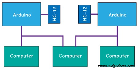
AT 命令:
示例 02
/*    Arduino Long Range Wireless Communication using HC-12
    Example 02 - Changing channels using push buttons - Buttons side
   by Dejan Nedelkovski, www.HowToMechatronics.com
*/

#include <SoftwareSerial.h>

#define setPin 6
#define button1 4
#define button2 3

SoftwareSerial HC12(10, 11);         // HC-12 TX Pin, HC-12 RX Pin

byte incomingByte;
String readBuffer = "";

int button1State = 0;
int button1Pressed = 0;
int button2State = 0;
int button2Pressed = 0;

void setup() {
  Serial.begin(9600);                   // Open serial port to computer
  HC12.begin(9600);                     // Open serial port to HC12
  pinMode(setPin, OUTPUT);
  pinMode(button1, INPUT);
  pinMode(button2, INPUT);
  digitalWrite(setPin, HIGH);           // HC-12 normal, transparent mode
}

void loop() {
  // ==== Storing the incoming data into a String variable
  while (HC12.available()) {             // If HC-12 has data
    incomingByte = HC12.read();          // Store each icoming byte from HC-12
    readBuffer += char(incomingByte);    // Add each byte to ReadBuffer string variable
  }
  delay(100);
  // ==== Sending data from one HC-12 to another via the Serial Monitor
  while (Serial.available()) {
    HC12.write(Serial.read());
  }

  // ==== If button 1 is pressed, set the channel 01
  button1State = digitalRead(button1);
  if (button1State == HIGH & button1Pressed == LOW) {
    button1Pressed = HIGH;
    delay(20);
  }
  if (button1Pressed == HIGH) {
    HC12.print("AT+C001");               // Send the AT Command to the other module
    delay(100);
    //Set AT Command Mode
    digitalWrite(setPin, LOW);           // Set HC-12 into AT Command mode
    delay(100);                          // Wait for the HC-12 to enter AT Command mode
    HC12.print("AT+C001");               // Send AT Command to HC-12
    delay(200);
    while (HC12.available()) {           // If HC-12 has data (the AT Command response)
      Serial.write(HC12.read());         // Send the data to Serial monitor
    }
    Serial.println("Channel successfully changed");
    digitalWrite(setPin, HIGH);          // Exit AT Command mode
    button1Pressed = LOW;
  }

  // ====  If button 2 is pressed, set the channel 02
  button2State = digitalRead(button2);
  if (button2State == HIGH & button2Pressed == LOW) {
    button2Pressed = HIGH;
    delay(100);
  }
  if (button2Pressed == HIGH) {
    HC12.print("AT+C002"); // Send the AT Command to the other module
    delay(100);
    //Set AT Command Mode
    digitalWrite(setPin, LOW);           // Set HC-12 into AT Command mode
    delay(100);                          // Wait for the HC-12 to enter AT Command mode
    HC12.print("AT+C002");               // Send AT Command to HC-12
    delay(200);
    while (HC12.available()) {           // If HC-12 has data (the AT Command response)
      Serial.write(HC12.read());         // Send the data to Serial monitor
    }
    Serial.println("Channel successfully changed");
    digitalWrite(setPin, HIGH);
    button2Pressed = LOW;
  }
  checkATCommand();
  readBuffer = "";                       // Clear readBuffer
}
// ==== Custom function - Check whether we have received an AT Command via the Serial Monitor
void checkATCommand () {
  if (readBuffer.startsWith("AT")) {     // Check whether the String starts with "AT"
    digitalWrite(setPin, LOW);           // Set HC-12 into AT Command mode
    delay(200);                          // Wait for the HC-12 to enter AT Command mode
    HC12.print(readBuffer);              // Send AT Command to HC-12
    delay(200);
    while (HC12.available()) {           // If HC-12 has data (the AT Command response)
      Serial.write(HC12.read());         // Send the data to Serial monitor
    }
    digitalWrite(setPin, HIGH);          // Exit AT Command mode
  }
}Code language: Arduino (arduino)/* Arduino Long Range Wireless Communication using HC-12
Example 02 - Changing channels using push buttons
by Dejan Nedelkovski, www.HowToMechatronics.com
*/
#include <SoftwareSerial.h>
#define setPin 6
SoftwareSerial HC12(10, 11); // HC-12 TX Pin, HC-12 RX Pin
byte incomingByte;
String readBuffer = "";
void setup() {
Serial.begin(9600); // Open serial port to computer
HC12.begin(9600); // Open serial port to HC12
pinMode(setPin, OUTPUT);
digitalWrite(setPin, HIGH); // HC-12 normal mode
}
void loop() {
// ==== Storing the incoming data into a String variable
while (HC12.available()) { // If HC-12 has data
incomingByte = HC12.read(); // Store each icoming byte from HC-12
readBuffer += char(incomingByte); // Add each byte to ReadBuffer string variable
}
delay(100);
// ==== Sending data from one HC-12 to another via the Serial Monitor
while (Serial.available()) {
HC12.write(Serial.read());
}
// === If button 1 is pressed, set channel 01
if (readBuffer == "AT+C001") {
digitalWrite(setPin, LOW); // Set HC-12 into AT Command mode
delay(100); // Wait for the HC-12 to enter AT Command mode
HC12.print(readBuffer); // Send AT Command to HC-12 ("AT+C001")
delay(200);
while (HC12.available()) { // If HC-12 has data (the AT Command response)
Serial.write(HC12.read()); // Send the data to Serial monitor
}
Serial.println("Channel successfully changed");
digitalWrite(setPin, HIGH); // Exit AT Command mode
readBuffer = "";
}
// === If button 2 is pressed, set channel 02
if (readBuffer == "AT+C002") {
digitalWrite(setPin, LOW); // Set HC-12 into AT Command mode
delay(100); // Wait for the HC-12 to enter AT Command mode
HC12.print(readBuffer); // Send AT Command to HC-12
delay(200);
while (HC12.available()) { // If HC-12 has data (the AT Command response)
Serial.write(HC12.read()); // Send the data to Serial monitor
}
Serial.println("Channel successfully changed");
digitalWrite(setPin, HIGH); // Exit AT Command mode
readBuffer = "";
}
checkATCommand();
readBuffer = ""; // Clear readBuffer
}
// ==== Custom function - Check whether we have received an AT Command via the Serial Monitor
void checkATCommand () {
if (readBuffer.startsWith("AT")) { // Check whether the String starts with "AT"
digitalWrite(setPin, LOW); // Set HC-12 into AT Command mode
delay(100); // Wait for the HC-12 to enter AT Command mode
HC12.print(readBuffer); // Send AT Command to HC-12
delay(200);
while (HC12.available()) { // If HC-12 has data (the AT Command response)
Serial.write(HC12.read()); // Send the data to Serial monitor
}
digitalWrite(setPin, HIGH); // Exit AT Command mode
}
}Code language: Arduino (arduino)// ==== Storing the incoming data into a String variable
while (HC12.available()) { // If HC-12 has data
incomingByte = HC12.read(); // Store each icoming byte from HC-12
readBuffer += char(incomingByte); // Add each byte to ReadBuffer string variable
}Code language: Arduino (arduino)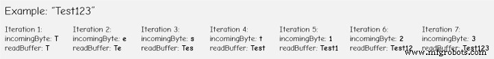
if (button1Pressed == HIGH) {
    HC12.print("AT+C001");               // Send the AT Command to the other module
    delay(100);
    //Set AT Command Mode
    digitalWrite(setPin, LOW);           // Set HC-12 into AT Command mode
    delay(100);                          // Wait for the HC-12 to enter AT Command mode
    HC12.print("AT+C001");               // Send AT Command to HC-12
    delay(200);
    while (HC12.available()) {           // If HC-12 has data (the AT Command response)
      Serial.write(HC12.read());         // Send the data to Serial monitor
    }
    Serial.println("Channel successfully changed");
    digitalWrite(setPin, HIGH);          // Exit AT Command mode
    button1Pressed = LOW;
}Code language: Arduino (arduino)// At the second Arduino
// === If button 1 is pressed, set channel 01
if (readBuffer == "AT+C001") {
digitalWrite(setPin, LOW); // Set HC-12 into AT Command mode
delay(100); // Wait for the HC-12 to enter AT Command mode
HC12.print(readBuffer); // Send AT Command to HC-12 ("AT+C001")
delay(200);
while (HC12.available()) { // If HC-12 has data (the AT Command response)
Serial.write(HC12.read()); // Send the data to Serial monitor
}
Serial.println("Channel successfully changed");
digitalWrite(setPin, HIGH); // Exit AT Command mode
readBuffer = "";
}Code language: Arduino (arduino)while (HC12.available()) { // If HC-12 has data (the AT Command response)
Serial.write(HC12.read()); // Send the data to Serial monitor
}Code language: Arduino (arduino)// ==== Custom function - Check whether we have received an AT Command via the Serial Monitor
void checkATCommand () {
if (readBuffer.startsWith("AT")) { // Check whether the String starts with "AT"
digitalWrite(setPin, LOW); // Set HC-12 into AT Command mode
delay(200); // Wait for the HC-12 to enter AT Command mode
HC12.print(readBuffer); // Send AT Command to HC-12
delay(200);
while (HC12.available()) { // If HC-12 has data (the AT Command response)
Serial.write(HC12.read()); // Send the data to Serial monitor
}
digitalWrite(setPin, HIGH); // Exit AT Command mode
}
}Code language: Arduino (arduino)HC-12 无线通信:使用加速度计的步进电机控制
/*   Arduino Long Range Wireless Communication using HC-12
     Example 03 - Stepper Motor Control using Accelerometer - Transmitter, Accelerometer
    by Dejan Nedelkovski, www.HowToMechatronics.com
*/

#include <SoftwareSerial.h>
#include <Wire.h>

SoftwareSerial HC12(10, 11); // HC-12 TX Pin, HC-12 RX Pin

float angle;
int lastAngle = 0;
int count = 0;
int angleSum = 0;

//--- Accelerometer Register Addresses
#define Power_Register 0x2D
#define X_Axis_Register_DATAX0 0x32 // Hexadecima address for the DATAX0 internal register.
#define X_Axis_Register_DATAX1 0x33 // Hexadecima address for the DATAX1 internal register.
#define Y_Axis_Register_DATAY0 0x34
#define Y_Axis_Register_DATAY1 0x35
#define Z_Axis_Register_DATAZ0 0x36
#define Z_Axis_Register_DATAZ1 0x37
int ADXAddress = 0x53;  //Device address in which is also included the 8th bit for selecting the mode, read in this case.
int X0, X1, X_out;
int Y0, Y1, Y_out;
int Z1, Z0, Z_out;
float Xa, Ya, Za;

void setup() {
  HC12.begin(9600);               // Open serial port to HC12
  Wire.begin(); // Initiate the Wire library
  Serial.begin(9600);
  delay(100);

  Wire.beginTransmission(ADXAddress);
  Wire.write(Power_Register); // Power_CTL Register
  // Enable measurement
  Wire.write(8); // Bit D3 High for measuring enable (0000 1000)
  Wire.endTransmission();
}
void loop() {
  // X-axis
  Wire.beginTransmission(ADXAddress); // Begin transmission to the Sensor
  //Ask the particular registers for data
  Wire.write(X_Axis_Register_DATAX0);
  Wire.write(X_Axis_Register_DATAX1);
  Wire.endTransmission(); // Ends the transmission and transmits the data from the two registers
  Wire.requestFrom(ADXAddress, 2); // Request the transmitted two bytes from the two registers
  if (Wire.available() <= 2) { //
    X0 = Wire.read(); // Reads the data from the register
    X1 = Wire.read();
    /* Converting the raw data of the X-Axis into X-Axis Acceleration
      - The output data is Two's complement
      - X0 as the least significant byte
      - X1 as the most significant byte */
    X1 = X1 << 8;
    X_out = X0 + X1;
    Xa = X_out / 256.0; // Xa = output value from -1 to +1, Gravity acceleration acting on the X-Axis
  }
  //Serial.print("Xa= ");
  //Serial.println(X_out);

  // Y-Axis
  Wire.beginTransmission(ADXAddress);
  Wire.write(Y_Axis_Register_DATAY0);
  Wire.write(Y_Axis_Register_DATAY1);
  Wire.endTransmission();
  Wire.requestFrom(ADXAddress, 2);
  if (Wire.available() <= 2) {
    Y0 = Wire.read();
    Y1 = Wire.read();
    Y1 = Y1 << 8;
    Y_out = Y0 + Y1;
    Ya = Y_out / 256.0;
  }

  // Combine X and Y values for getting the angle value from 0 to 180 degrees
  if (Y_out > 0) {
    angle = map(Y_out, 0, 256, 90, 0);
  }
  else if (Y_out < 0) {
    angle = map(Y_out, 256, 0, 90, 0);
    angle = 90 - angle;
  }
  if (X_out < 0 & Y_out < 0) {
    angle = 180;
  }
  if (X_out < 0 & Y_out >0) {
    angle = 0;
  }

  // float to int
  int angleInt = int(angle);
  // Makes 100 accelerometer readings and sends the average for smoother result
  angleSum = angleSum + angleInt;
  count++;
  if (count >= 100) {
    angleInt = angleSum / 100;
    angleSum = 0;
    count = 0;
    // Some more smoothing of acceleromter reading - sends the new angle only if it differes from the previous one by +-2
    if (angleInt > lastAngle + 2 || angleInt < lastAngle - 2) {
      Serial.println(angleInt);
      String angleString = String(angleInt);
      //sends the angle value with start marker "s" and end marker "e"
      HC12.print("s" + angleString + "e");
      delay(10);
      lastAngle = angleInt;
      angleSum = 0;
      count = 0;
    }
  }
}
Code language: Arduino (arduino)/* Arduino Long Range Wireless Communication using HC-12
Example 03 - Stepper Motor Control using Accelerometer - Receiver, Stepper Motor
by Dejan Nedelkovski, www.HowToMechatronics.com
*/
#include <SoftwareSerial.h>
SoftwareSerial HC12(10, 11); // HC-12 TX Pin, HC-12 RX Pin
char incomingByte;
String readBuffer = "";
// defines pins numbers
const int dirPin = 4;
const int stepPin = 3;
const int button = 2;
int currentAngle = 0;
int lastAngle = 0;
int rotate = 0;
void setup() {
Serial.begin(9600); // Open serial port to computer
HC12.begin(9600); // Open serial port to HC12
// Sets the two pins as Outputs
pinMode(dirPin, OUTPUT);
pinMode(stepPin, OUTPUT);
// Microswitch input, with internal pull-up resistor activated
pinMode(button, INPUT_PULLUP);
delay(10);
digitalWrite(dirPin, HIGH);
boolean startingPosition = true;
while (startingPosition) {
digitalWrite(stepPin, HIGH);
delayMicroseconds(200);
digitalWrite(stepPin, LOW);
delayMicroseconds(200);
if (digitalRead(button) == LOW) {
startingPosition = false;
}
}
delay(100);
}
void loop() {
readBuffer = "";
boolean start = false;
// Reads the incoming angle
while (HC12.available()) { // If HC-12 has data
incomingByte = HC12.read(); // Store each icoming byte from HC-12
delay(5);
// Reads the data between the start "s" and end marker "e"
if (start == true) {
if (incomingByte != 'e') {
readBuffer += char(incomingByte); // Add each byte to ReadBuffer string variable
}
else {
start = false;
}
}
// Checks whether the received message statrs with the start marker "s"
else if ( incomingByte == 's') {
start = true; // If true start reading the message
}
}
// Converts the string into integer
currentAngle = readBuffer.toInt();
// Makes sure it uses angles between 0 and 180
if (currentAngle > 0 && currentAngle < 180) {
// Convert angle value to steps (depending on the selected step resolution)
// A cycle = 200 steps, 180deg = 100 steps ; Resolution: Sixteenth step x16
currentAngle = map(currentAngle, 0, 180, 0, 1600);
//Serial.println(currentAngle); // Prints the angle on the serial monitor
digitalWrite(dirPin, LOW); // Enables the motor to move in a particular direction
// Rotates the motor the amount of steps that differs from the previous positon
if (currentAngle != lastAngle) {
if (currentAngle > lastAngle) {
rotate = currentAngle - lastAngle;
for (int x = 0; x < rotate; x++) {
digitalWrite(stepPin, HIGH);
delayMicroseconds(400);
digitalWrite(stepPin, LOW);
delayMicroseconds(400);
}
}
// rotate the other way
if (currentAngle < lastAngle) {
rotate = lastAngle - currentAngle;
digitalWrite(dirPin, HIGH); //Changes the rotations direction
for (int x = 0; x < rotate; x++) {
digitalWrite(stepPin, HIGH);
delayMicroseconds(400);
digitalWrite(stepPin, LOW);
delayMicroseconds(400);
}
}
}
lastAngle = currentAngle; // Remembers the current/ last positon
}
}Code language: Arduino (arduino)// Makes 100 accelerometer readings and sends the average for smoother result
angleSum = angleSum + angleInt;
count++;
if (count >= 100) {
angleInt = angleSum / 100;
angleSum = 0;
count = 0;
// Some more smoothing of acceleromter reading - sends the new angle only if it differes from the previous one by +-2
if (angleInt > lastAngle + 2 || angleInt < lastAngle - 2) {
Serial.println(angleInt);
String angleString = String(angleInt);
//sends the angle value with start marker "s" and end marker "e"
HC12.print("s" + angleString + "e");
delay(10);
lastAngle = angleInt;
angleSum = 0;
count = 0;
}
}Code language: Arduino (arduino)// Reads the incoming angle
while (HC12.available()) { // If HC-12 has data
incomingByte = HC12.read(); // Store each icoming byte from HC-12
delay(5);
// Reads the data between the start "s" and end marker "e"
if (start == true) {
if (incomingByte != 'e') {
readBuffer += char(incomingByte); // Add each byte to ReadBuffer string variable
}
else {
start = false;
}
}
// Checks whether the received message statrs with the start marker "s"
else if ( incomingByte == 's') {
start = true; // If true start reading the message
}
}Code language: Arduino (arduino)
制造工艺