

Verilog 生成块
generate 块允许乘以模块实例或执行任何模块的条件实例化。它提供了基于 Verilog 参数构建设计的能力。当需要多次重复相同的操作或模块实例,或者必须根据给定的 Verilog 参数有条件地包含某些代码时,这些语句特别方便。
generate 块不能包含端口、参数、specparam 声明或 specify 块。但是,允许使用其他模块项和其他生成块。所有生成实例都在 module 中编码 以及关键字 generate 之间 和 endgenerate .
生成的实例可以有模块、连续赋值、always 或 initial 块和用户定义的原语。有两种类型的生成构造 - 循环和条件。
- 生成for循环
- 否则生成
- 生成案例
生成循环
半加器将在另一个名为 my_design 的顶层设计模块中使用 generate 实例化 N 次 for 循环构造。循环变量必须使用关键字 genvar 声明 它告诉工具该变量将在生成块的详细说明期间专门使用。
// Design for a half-adder
module ha ( input   a, b,
            output  sum, cout);

  assign sum  = a ^ b;
  assign cout = a & b;
endmodule

// A top level design that contains N instances of half adder
module my_design
	#(parameter N=4)
		(	input [N-1:0] a, b,
			output [N-1:0] sum, cout);

	// Declare a temporary loop variable to be used during
	// generation and won't be available during simulation
	genvar i;

	// Generate for loop to instantiate N times
	generate
		for (i = 0; i < N; i = i + 1) begin
          ha u0 (a[i], b[i], sum[i], cout[i]);
		end
	endgenerate
endmodule
测试台
testbench 参数用于控制设计中半加器实例的数量。当 N 为 2 时,my_design 将有两个半加器实例。
module tb;
	parameter N = 2;
  reg  [N-1:0] a, b;
  wire [N-1:0] sum, cout;

  // Instantiate top level design with N=2 so that it will have 2
  // separate instances of half adders and both are given two separate
  // inputs
  my_design #(.N(N)) md( .a(a), .b(b), .sum(sum), .cout(cout));

  initial begin
    a <= 0;
    b <= 0;

    $monitor ("a=0x%0h b=0x%0h sum=0x%0h cout=0x%0h", a, b, sum, cout);

    #10 a <= 'h2;
    		b <= 'h3;
    #20 b <= 'h4;
    #10 a <= 'h5;
  end
endmodule
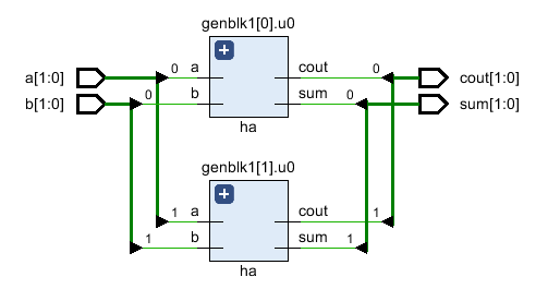
a[0] 和 b[0] 给出输出 sum[0] 和 cout[0] 而 a[1] 和 b[1] 给出输出 sum[1] 和 cout[1]。
模拟日志ncsim> run a=0x0 b=0x0 sum=0x0 cout=0x0 a=0x2 b=0x3 sum=0x1 cout=0x2 a=0x2 b=0x0 sum=0x2 cout=0x0 a=0x1 b=0x0 sum=0x1 cout=0x0 ncsim: *W,RNQUIE: Simulation is complete. ncsim> exit
看到详细的 RTL 确实有两个由 generate 生成的半加法器实例 块。
生成如果
下面显示的是使用 if else 的示例 在 generate 内 构造以在两个不同的多路复用器实现之间进行选择。第一个设计使用 assign 实现多路复用器的语句,而第二个设计使用 case 陈述。在顶层设计模块中定义了一个名为 USE_CASE 的参数,用于在两个选项之间进行选择。
// Design #1: Multiplexer design uses an "assign" statement to assign
// out signal
module mux_assign ( input a, b, sel,
                   output out);
  assign out = sel ? a : b;

  // The initial display statement is used so that
  // we know which design got instantiated from simulation
  // logs
  initial
  	$display ("mux_assign is instantiated");
endmodule

// Design #2: Multiplexer design uses a "case" statement to drive
// out signal
module mux_case (input a, b, sel,
                 output reg out);
  always @ (a or b or sel) begin
  	case (sel)
    	0 : out = a;
   	 	1 : out = b;
  	endcase
  end

  // The initial display statement is used so that
  // we know which design got instantiated from simulation
  // logs
  initial
    $display ("mux_case is instantiated");
endmodule

// Top Level Design: Use a parameter to choose either one
module my_design (	input a, b, sel,
         			output out);
  parameter USE_CASE = 0;

  // Use a "generate" block to instantiate either mux_case
  // or mux_assign using an if else construct with generate
  generate
  	if (USE_CASE)
      mux_case mc (.a(a), .b(b), .sel(sel), .out(out));
    else
      mux_assign ma (.a(a), .b(b), .sel(sel), .out(out));
  endgenerate

endmodule
测试台
Testbench 实例化顶层模块 my_design 并将参数 USE_CASE 设置为 1,以便它使用 case 实例化设计 声明。
module tb;
	// Declare testbench variables
  reg a, b, sel;
  wire out;
  integer i;

  // Instantiate top level design and set USE_CASE parameter to 1 so that
  // the design using case statement is instantiated
  my_design #(.USE_CASE(1)) u0 ( .a(a), .b(b), .sel(sel), .out(out));

  initial begin
  	// Initialize testbench variables
  	a <= 0;
    b <= 0;
    sel <= 0;

    // Assign random values to DUT inputs with some delay
    for (i = 0; i < 5; i = i + 1) begin
      #10 a <= $random;
      	  b <= $random;
          sel <= $random;
      $display ("i=%0d a=0x%0h b=0x%0h sel=0x%0h out=0x%0h", i, a, b, sel, out);
    end
  end
endmodule
当参数USE_CASE为1时,从仿真日志可以看出多路复用器设计使用case 语句被实例化。而当USE_CASE为零时,复用器设计使用assign 语句被实例化。这可以从模拟日志中打印的显示语句中看到。
// When USE_CASE = 1
ncsim> run
mux_case is instantiated
i=0 a=0x0 b=0x0 sel=0x0 out=0x0
i=1 a=0x0 b=0x1 sel=0x1 out=0x1
i=2 a=0x1 b=0x1 sel=0x1 out=0x1
i=3 a=0x1 b=0x0 sel=0x1 out=0x0
i=4 a=0x1 b=0x0 sel=0x1 out=0x0
ncsim: *W,RNQUIE: Simulation is complete.

// When USE_CASE = 0
ncsim> run
mux_assign is instantiated
i=0 a=0x0 b=0x0 sel=0x0 out=0x0
i=1 a=0x0 b=0x1 sel=0x1 out=0x0
i=2 a=0x1 b=0x1 sel=0x1 out=0x1
i=3 a=0x1 b=0x0 sel=0x1 out=0x1
i=4 a=0x1 b=0x0 sel=0x1 out=0x1
ncsim: *W,RNQUIE: Simulation is complete.
生成案例
生成案例允许基于 case 在另一个模块中实例化模块、初始块和始终块 表达式来选择众多选项之一。
// Design #1: Half adder
module ha (input a, b,
           output reg sum, cout);
  always @ (a or b)
  {cout, sum} = a + b;

  initial
    $display ("Half adder instantiation");
endmodule

// Design #2: Full adder
module fa (input a, b, cin,
           output reg sum, cout);
  always @ (a or b or cin)
  {cout, sum} = a + b + cin;

    initial
      $display ("Full adder instantiation");
endmodule

// Top level design: Choose between half adder and full adder
module my_adder (input a, b, cin,
                 output sum, cout);
  parameter ADDER_TYPE = 1;

  generate
    case(ADDER_TYPE)
      0 : ha u0 (.a(a), .b(b), .sum(sum), .cout(cout));
      1 : fa u1 (.a(a), .b(b), .cin(cin), .sum(sum), .cout(cout));
    endcase
  endgenerate
endmodule
测试台
module tb;
  reg a, b, cin;
  wire sum, cout;

  my_adder #(.ADDER_TYPE(0)) u0 (.a(a), .b(b), .cin(cin), .sum(sum), .cout(cout));

  initial begin
    a <= 0;
    b <= 0;
    cin <= 0;

    $monitor("a=0x%0h b=0x%0h cin=0x%0h cout=0%0h sum=0x%0h",
             a, b, cin, cout, sum);

    for (int i = 0; i < 5; i = i + 1) begin
      #10 a <= $random;
      b <= $random;
      cin <= $random;
    end
  end
endmodule
请注意,因为实例化了半加器,所以 cin 对输出 sum 和 cout 没有任何影响。
模拟日志ncsim> run Half adder instantiation a=0x0 b=0x0 cin=0x0 cout=00 sum=0x0 a=0x0 b=0x1 cin=0x1 cout=00 sum=0x1 a=0x1 b=0x1 cin=0x1 cout=01 sum=0x0 a=0x1 b=0x0 cin=0x1 cout=00 sum=0x1 ncsim: *W,RNQUIE: Simulation is complete.
Verilog