


将Quartus Prime IP库集成进VUnit:分步实战指南
你是否想在VUnit验证框架中运行包含Quartus IP核的VHDL仿真?
FPGA工程师Konstantinos Paraskevopoulos有此需求,却找不到合适教程。幸而他凭才华攻克并慷慨分享给VHDLwhiz,成就这篇客座文章。
有请Konstantinos!
在用VUnit仿真系统时,常需引入Quartus IP目录的预定义IP。本教程提供生成、合并、链接外部Quartus IP库至VUnit环境所需知识。
VUnit新手?查阅:VUnit入门教程
概览
教程含三主体:
- 所选IP简述
- 生成与链接库的步骤
- 利用VUnit与ModelSim验证
前置条件
- Quartus
- 下载Quartus Prime
- QSYS需在PATH中(STEP 2命令行选项)
- Intel ModelSim
- 参考此文免费安装ModelSim
- ModelSim需在PATH中
- VUnit
- 参考此文免费安装VUnit
- Python 3.6+
- 下载Python
- Python需在PATH中
假设具备基础VHDL与ModelSim技能。
待测设计
场景使用Quartus整数运算IP列表中的并行加法器IP。
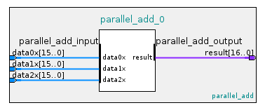
设计接收三路16位输入向量,输出17位加法结果。
步骤1:生成IP
在IP目录窗口双击Library/Basic functions/Arithmetic下的并行加法器组件。
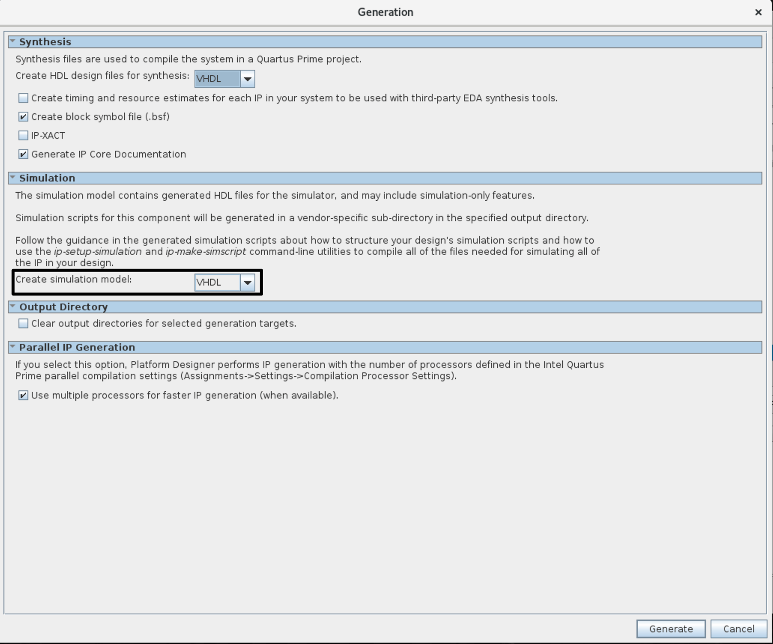
命名并按需定制后,点击右下角Generate HDL按钮。
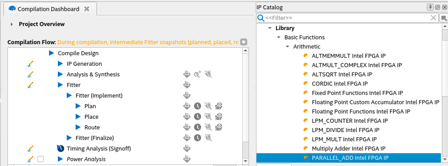
弹出窗口如下图。
注意:必须在Simulation区将Create simulation model设为VHDL或Verilog以生成仿真文件,默认none会导致given_ip_name.spd不生成,致使下一步失败。
上述过程在quartus目录下生成文件与文件夹:
- 文件:
given_ip_name.ip - 文件夹:
given_ip_name
文件夹含.vhd与.v文件,稍后加入run.py脚本。
步骤2:生成IP仿真文件
- GUI: 选Tools ➤ Generate Simulator Setup Script for IP,在提示窗口指定输出目录。
- CMD: 用Qsys命令生成同等文件,终端执行:
ip-setup-simulation --quartus-project= <project's_QPF_filepath> \ --output-directory= <my_dir>任一方法均指示Quartus为各支持仿真器生成目录,内含创建编译IP库的脚本。
步骤3:为ModelSim生成并编译IP库
在上一步创建的mentor文件夹中找到msim_setup.tcl脚本,复制重命名为setup.tcl。在setup.tcl中取消注释示例命令并设置$QSYS_SIMDIR变量。
# # QSYS_SIMDIR is used in the Quartus-generated IP simulation script to # # construct paths to the files required to simulate the IP in your Quartus # # project. By default, the IP script assumes that you are launching the # # simulator from the IP script location. If launching from another # # location, set QSYS_SIMDIR to the output directory you specified when you # # generated the IP script, relative to the directory from which you launch # # the simulator. # set QSYS_SIMDIR <script generation output directory> # # # Source the generated IP simulation script. source $QSYS_SIMDIR/mentor/msim_setup.tcl # # # Set any compilation options you require (this is unusual). # set USER_DEFINED_COMPILE_OPTIONS <compilation options> # set USER_DEFINED_VHDL_COMPILE_OPTIONS <compilation options for VHDL> # set USER_DEFINED_VERILOG_COMPILE_OPTIONS <compilation options for Verilog> # # # Call command to compile the Quartus EDA simulation library. dev_com # # # Call command to compile the Quartus-generated IP simulation files. com # 修改保存setup.tcl后,用vsim命令执行Tcl文件。
vsim -c -do "do setup.tcl; quit"这在mentor文件夹生成编译后库。
步骤4:VUnit链接
IP库就绪,现在用Pythonrun.py脚本链接。
参考下图理解示例目录拓扑。初始拓扑含根目录demo、tb、vunit、quartus文件夹。quartus下所有子文件夹/文件经Quartus框架在建项目及完成步骤1-3后生成。
注意: Quartus生成更多文件/文件夹,下图仅展示相关者。
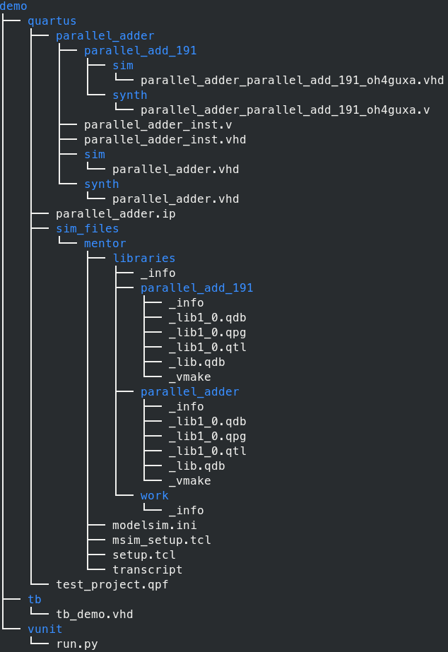
基于此拓扑视图,可指定ROOT路径与生成库路径,如下所示。
注sim_files为步骤2指定目录,存放mentor文件夹。
from vunit import VUnit from os.path import join, dirname, abspath # ROOT root = join(dirname(__file__), '../') # Path to generated libraries path_2_lib = '/quartus/sim_files/mentor/libraries/' # ROOT创建VUnit实例vu后,指定设计库并链接外部库:
# Create VUnit instance by parsing command line arguments vu = VUnit.from_argv() # create design's library my_lib = vu.add_library('my_lib') # Link external library vu.add_external_library("parallel_adder", root + path_2_lib + "parallel_adder")最后添加源文件。它们位于given_ip_name目录下三个子文件夹:
parallel_add_191synthsim
synth与sim目录含相同信息即IP顶层设计。本例格式为VHDL,取决于步骤1语言选择。
若顶层设计含子组件,亦须包含其源文件。它们位于given_ip_name下子文件夹,如本例parallel_add_191组件。
my_lib.add_source_files(join(root,'quartus','parallel_adder','sim','parallel_adder.vhd')) my_lib.add_source_files(join(root,'quartus','parallel_adder','parallel_add_191','sim','parallel_adder_parallel_add_191_oh4guxa.vhd')) my_lib.add_source_files(join(root,'tb','tb_demo.vhd')) testbench = my_lib.entity("tb_demo") vu.main()测试平台
先阅读此链接了解VUnit测试平台形成基础。
回到测试平台,添加必要VUnit库与其他库,定义信号。
注意: 示例中进程执行顺序。故用控制信号(称标志)通知进程是否开始/终止。
library IEEE; use IEEE.std_logic_1164.all; use ieee.numeric_std.all; library vunit_lib; context vunit_lib.vunit_context; entity tb_demo is generic ( runner_cfg : string:= runner_cfg_default); end tb_demo; architecture sim of tb_demo is constant clk_period : time := 10 ns; signal clk : std_logic := '0'; signal rst : std_logic := '0'; -- INPUTS signal data_a : std_logic_vector(0 to 15):= (others => '0'); signal data_b : std_logic_vector(0 to 15):= (others => '0'); signal data_c : std_logic_vector(0 to 15):= (others => '0'); -- OUTPUTS signal result : std_logic_vector(0 to 16); -- CONTROL FLAGS signal reset_done :boolean := false; signal sim_done :boolean := false; signal start_sim :boolean := false; 实例化UUT。Quartus在ip_name_inst.vhd与ip_name_inst.v提供VHDL/Verilog实例化示例。
begin -- Unit Under Test UUT : entity work.parallel_adder port map ( data0x => data_a, -- parallel_add_input.data0x data1x => data_b, -- .data1x data2x => data_c, -- .data2x result => result -- parallel_add_output.result );首个启动的两个进程为clk_process与reset_rel。后者复位驱动reset_done标志置true后挂起,前者贯穿仿真时段。
clk_process : process begin clk <= '1'; wait for clk_period/2; clk <= '0'; wait for clk_period/2; end process clk_process; reset_rel : process begin rst <= '1'; wait for clk_period*2; wait until rising_edge(clk); rst <= not rst; reset_done <= true; wait; end process reset_rel;复位完成,调用test_runner进程执行测试。测试运行器持续至sim_done标志置true(最后进程驱动)。
test_runner : process begin test_runner_setup(runner, runner_cfg); wait until reset_done and rising_edge(clk); iterate : while test_suite loop start_sim <= true; if run("test_case_1") then info ("Start"); info (running_test_case); wait until sim_done; end if; end loop; test_runner_cleanup(runner); end process test_runner; 最后data_generator进程通过for循环给并行加法器三路输入赋值,执行多次加法。
注意: 此进程由test_runner设置start_sim标志触发。结束时驱动sim_done标志,命令测试运行器暂停仿真。
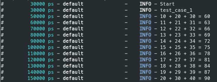
data_generator : process constant tag2 : log_level_t := new_log_level("INFO", fg => blue, bg => black, style => bright); variable a,b,c,d : integer; begin wait until start_sim; wait until rising_edge(clk); show(display_handler, tag2); if running_test_case = "test_case_1" then for i in 0 to 10 loop data_a <= std_logic_vector(to_unsigned(i+10,data_a'length)); data_b <= std_logic_vector(to_unsigned(i+20,data_a'length)); data_c <= std_logic_vector(to_unsigned(i+30,data_a'length)); wait until rising_edge(clk); a := to_integer(unsigned(data_a)); b := to_integer(unsigned(data_b)); c := to_integer(unsigned(data_c)); d := to_integer(unsigned(result)); log( integer'image(a) &" + " & integer'image(b) &" + " & integer'image(c) &" = " & integer'image(d), tag2); end loop; end if; sim_done <= true; end process data_generator; 验证
在run.py所在目录执行以下命令运行测试用例验证:
python ./run.py -v注意: 输出用定制logger美化,需加verbose -v选项可见。因仅定义单测试用例,无需指定用例选项。
在ModelSim中验证结果,可执行:
python ./run.py --gui
(点击图片放大)
结论
综上,我们学会了如何在VUnit环境中合并测试Quartus IP目录中的预定义IP。虽教程用预定义IP,同流程适用于自定义封装IP。
未读者请查阅:VUnit入门教程
VHDL