

Arduino 蓝牙控制电动相机滑块
组件和用品
 |
| × | 1 | |||
 |
| × | 1 | |||
| × | 1 | ||||
| × | 4 | ||||
| × | 4 | ||||
| × | 4 | ||||
| × | 4 | ||||
| × | 2 | ||||
| × | 2 | ||||
| × | 2 | ||||
| × | 2 | ||||
| × | 2 | ||||
| × | 4 | ||||
| × | 4 | ||||
| × | 8 | ||||
| × | 2 | ||||
| × | 1 | ||||
| × | 1 | ||||
| × | 1 | ||||
| × | 1 | ||||
| × | 1 | ||||
| × | 1 | ||||
| × | 1 | ||||
| × | 1 |
必要的工具和机器
 |
|
应用和在线服务
 |
| |||
| ||||
 |
|
关于这个项目
项目概况
对于喜欢随机拍摄一些业余爱好者视频的人来说,购买电动相机滑块有点贵。所以,我建立了自己的。在本教程中,我们将通过每一步来构建您自己的蓝牙控制电动相机滑块。
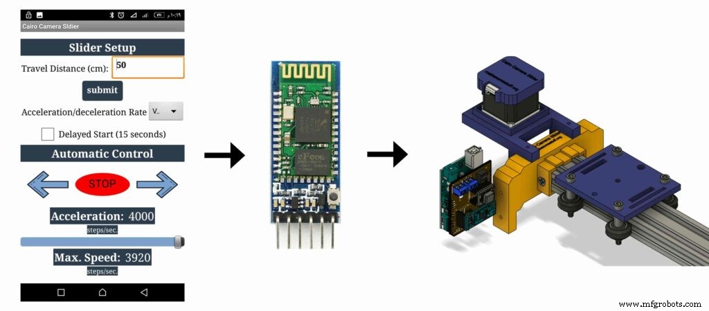
今天我们将构建一个电动相机滑块,我们可以从定制的安卓移动应用程序通过蓝牙无线控制它。我使用了“MIT Appinventor”工具来制作这个应用程序,它让我们能够控制很多东西,比如滑块的移动速度、移动距离、加速/减速率等等。移动应用程序非常强大,您可以在应用程序内设置您正在使用的相机滑块长度。这意味着,您可以自由构建长达 10 米的任何长度的实际相机滑块,而无需担心应用程序。
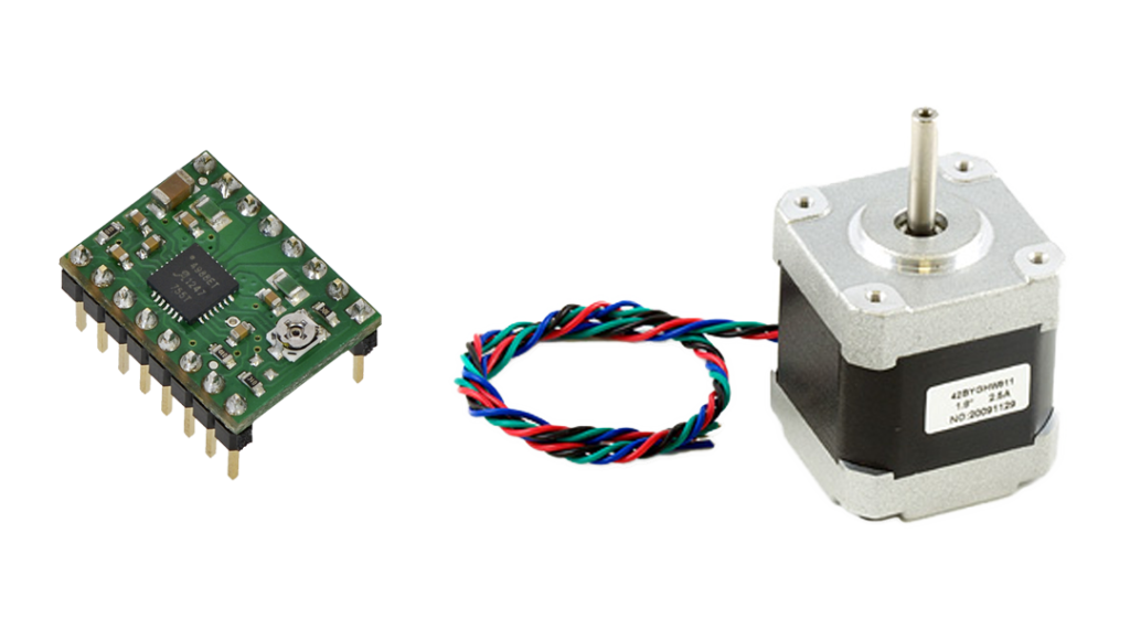
我们使用 NEMA17 步进电机作为执行器,因此我们可以控制相机滑块移动多少步。要使用 Arduino 板控制步进电机,我们需要一个翻译器,它接收来自 Arduino 板的命令并将其翻译成步进电机能够理解的语言。 A4988 Pololu 步进电机驱动器角色来了,它为我们提供了五种不同的微步分辨率(低至 1/16 步),以实现最大的移动精度和移动平滑度。
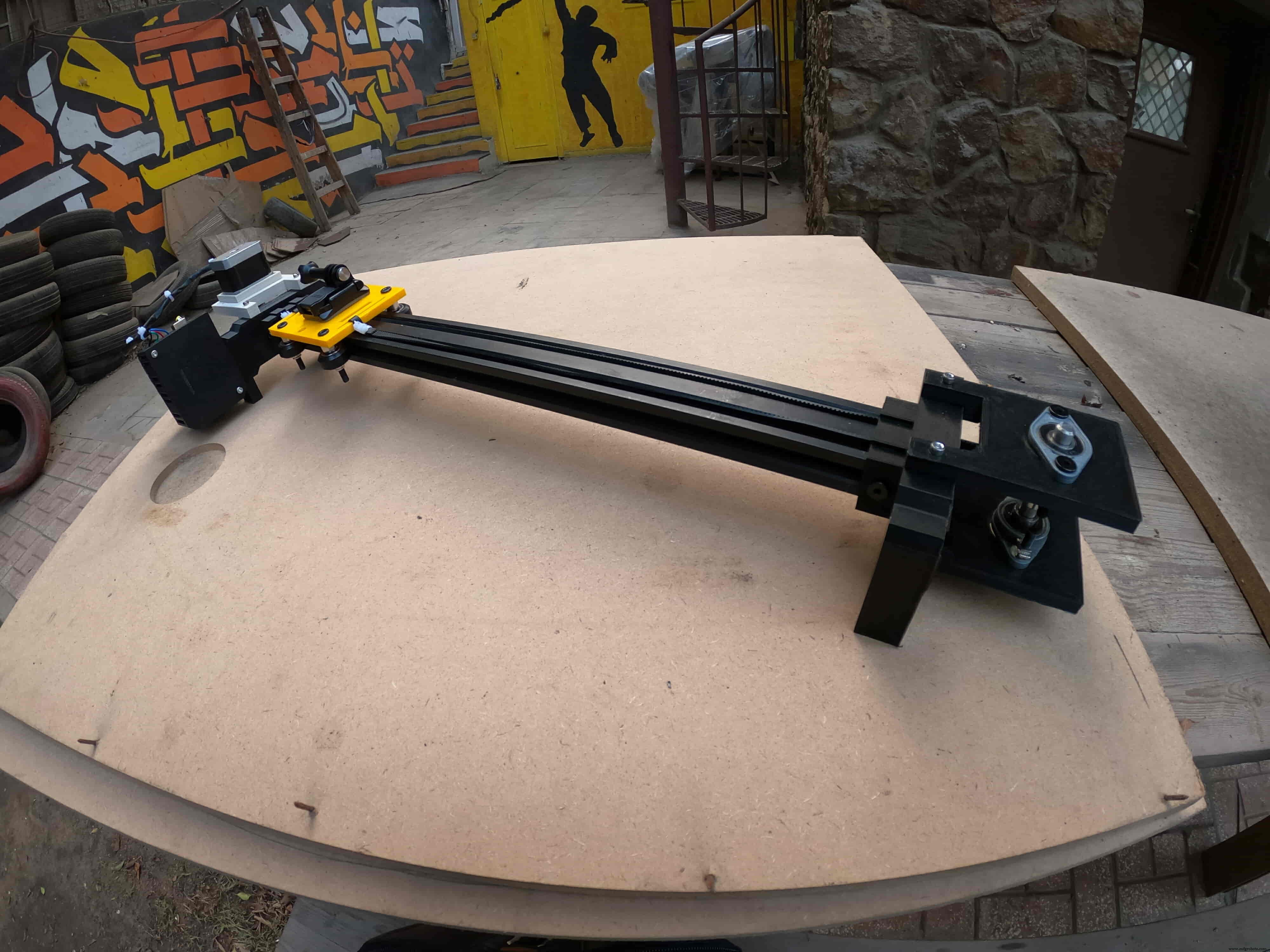
该项目在设计时考虑到了 fablab/makerspace/hackerspace 的可制造性。
CAD 和 3D 建模
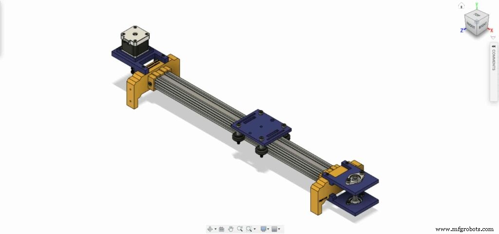
我们使用 Fusion360 来设计相机滑块,我们选择使用非常知名且易于找到的机械组件,无论您身在何处,您都可以从几乎任何在线或离线商店轻松购买。
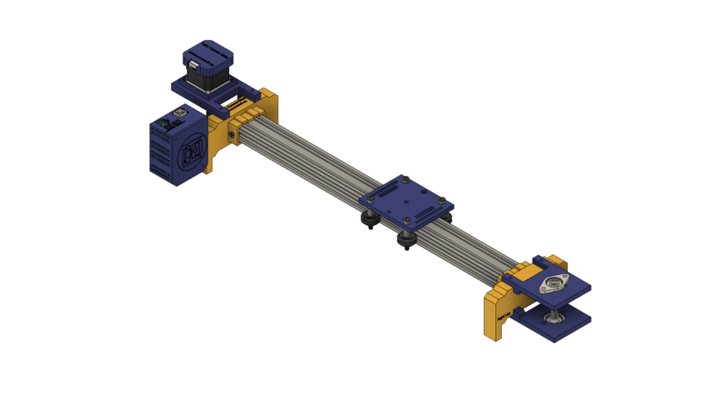
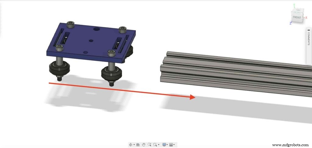
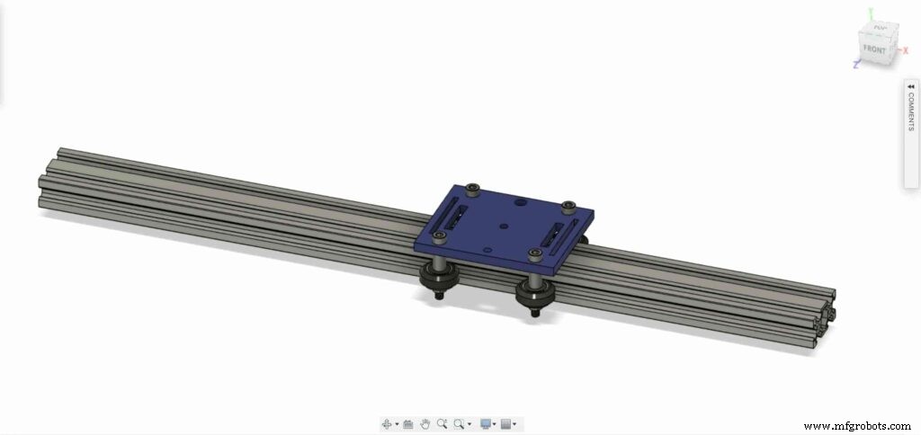
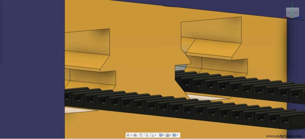
我们正在使用 Openbuilds 硬件来构建机械结构,V 型槽 2040 线性导轨作为相机移动的指南。两个滑轮,一个在步进电机轴上。另一个,在滑块对面的8mm直线导轨轴上,中间有一个开放的同步带,将步进电机的旋转运动转换为直线运动。
8mm直线导轨轴安装在两个用四个M5螺钉安装在顶板和底板上的自调心轴承座法兰轴承之间。
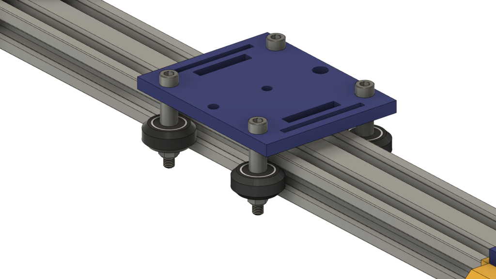
我们使用了四个 Delrin V-Slot 实心轮,它们在 V-Slot 导轨的 V 形槽中向下行驶,使相机移动非常顺畅。相机板中间有一个直径为 1/4 英寸的孔,用于安装标准三脚架螺丝,以便您轻松安装相机。
最后是电子设备外壳,所有相机滑块部件都通过 m3*16mm 螺钉和螺母固定在一起。
数字制造(3D 打印)
除了Camera滑块左右腿之外,所有的相机滑块主体都是3D打印的,0.2层高,20%填充,印刷0.2层高,50%填充。
您可以从下载 STL 文件 物联网。
V 型轮套件组装
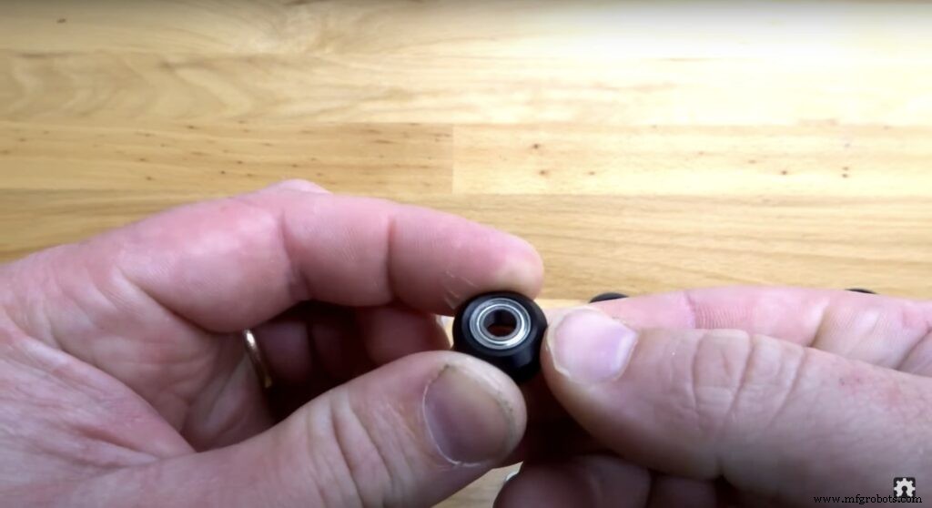
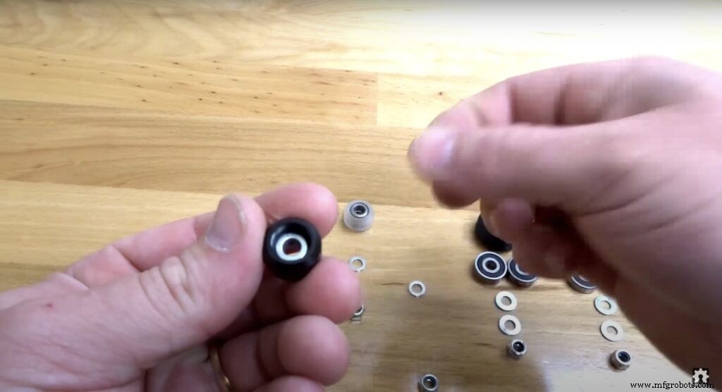
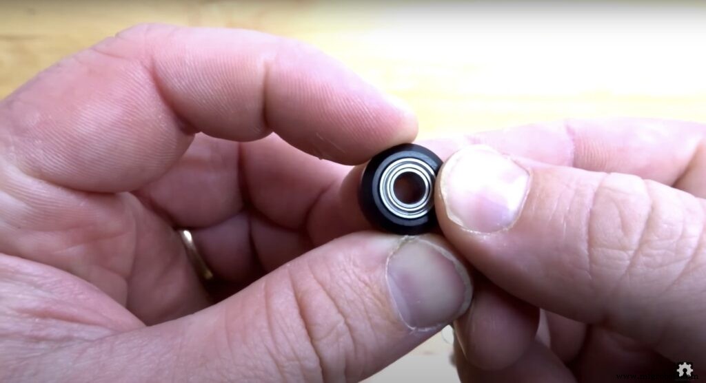
组装过程很简单,加油!第一步,我们需要组装四个实心 V 轮。实心 V 型轮套件配有一个橡胶轮、两个轴承、两个精密垫片和一个锁紧螺母。
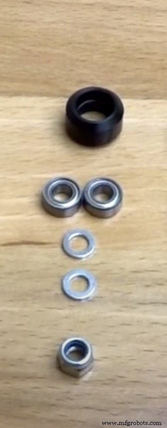
从橡胶轮的一侧插入轴承并将轮子翻转,然后在橡胶轮内插入一个精密垫片,最后从第二个面插入第二个轴承。
相机滑块机械组件
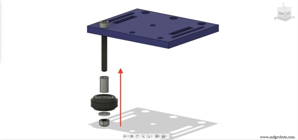
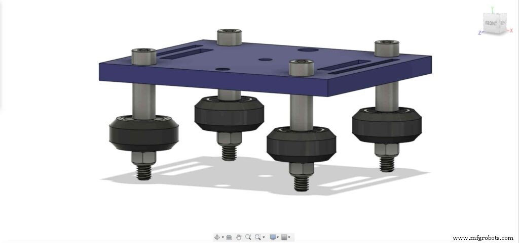
首先,我们需要组装相机板和四个实心 V 轮。使用9mm铝垫片、精密垫片和锁紧螺母。

我们将用其他三个轮子重复上一步。在右侧的两个轮子中,我们将使用 9 毫米垫片。而另外两个左轮我们将使用带有 3mm 垫片的偏心垫片而不是 9mm 垫片。
现在,将相机支架板插入 V 形槽型材中。如果发现盘子松动摆动,可以拧紧偏心螺母,直到得到牢固的盘子。
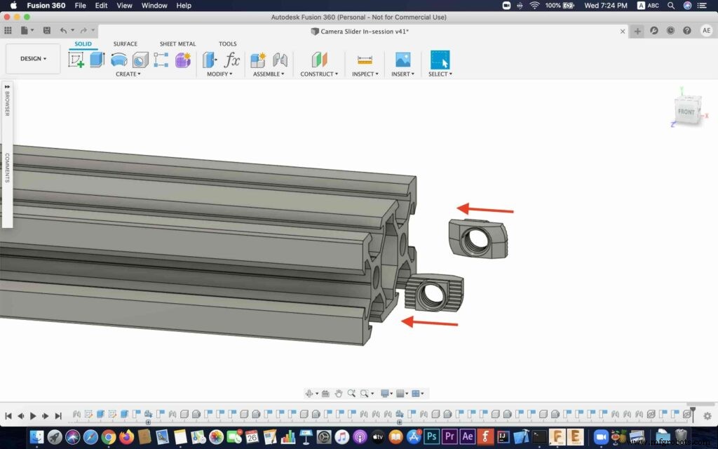
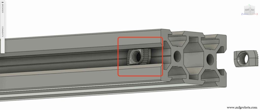
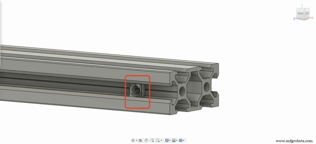
让我们在 V 形槽型材的每一端插入两个插入式三通螺母。我们需要将V型槽轮廓与相机滑块的左右腿连接起来。
取下两个相机滑块腿并将它们推入 V 形槽轮廓。
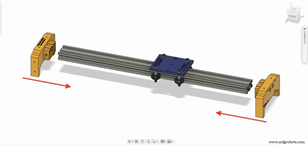

带上四颗M5X10mm螺丝,用V型槽型材固定两条腿。
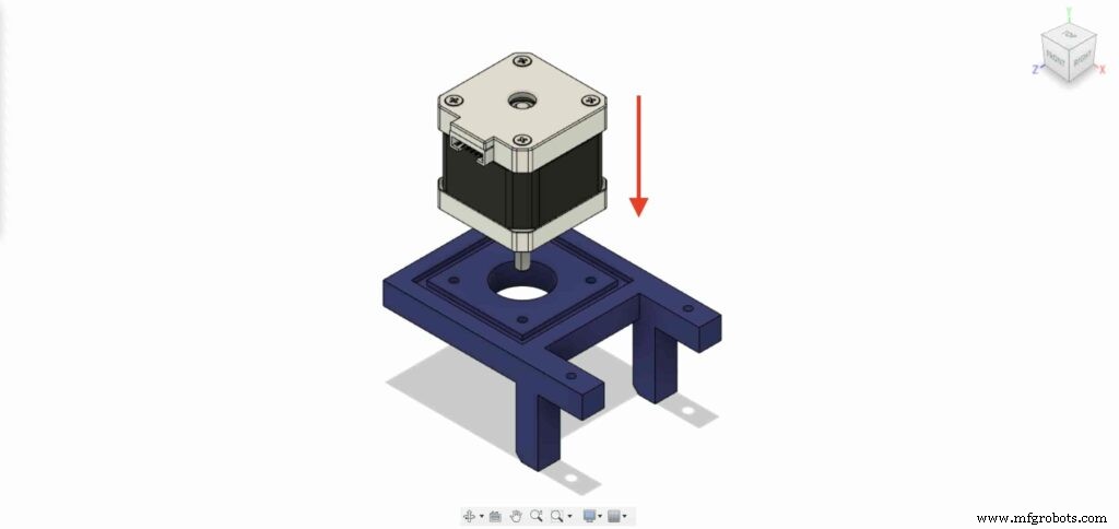
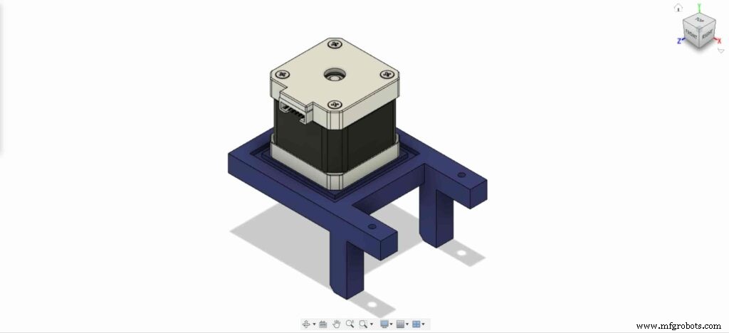
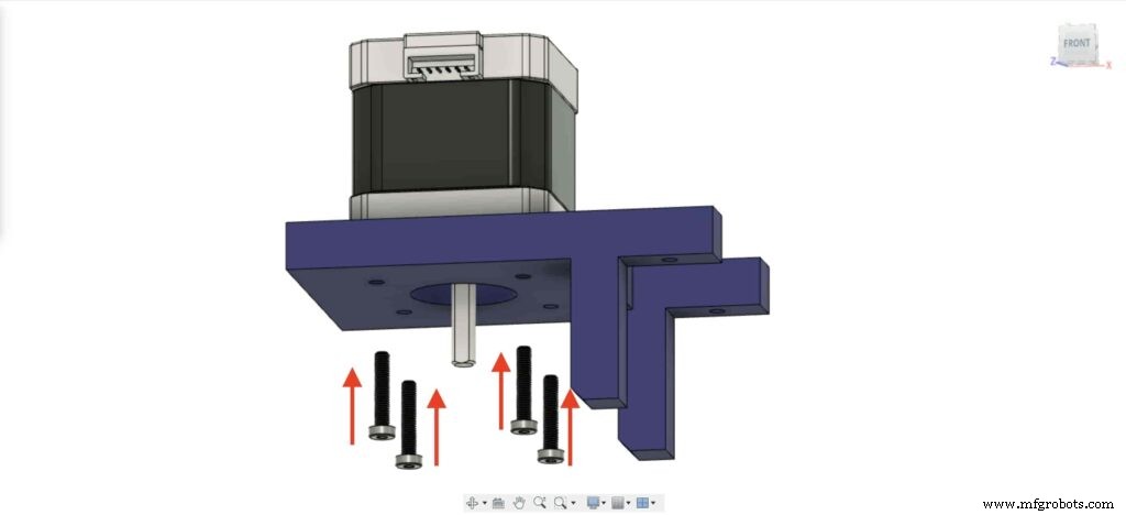
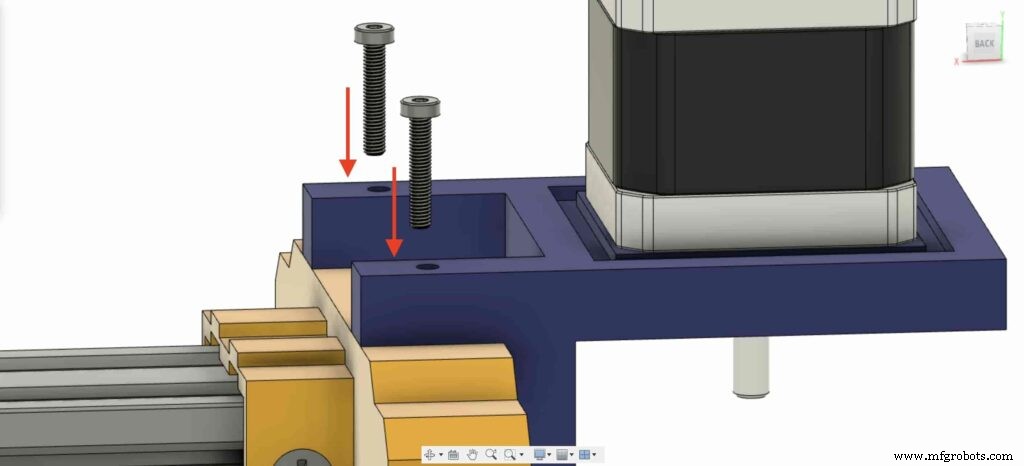
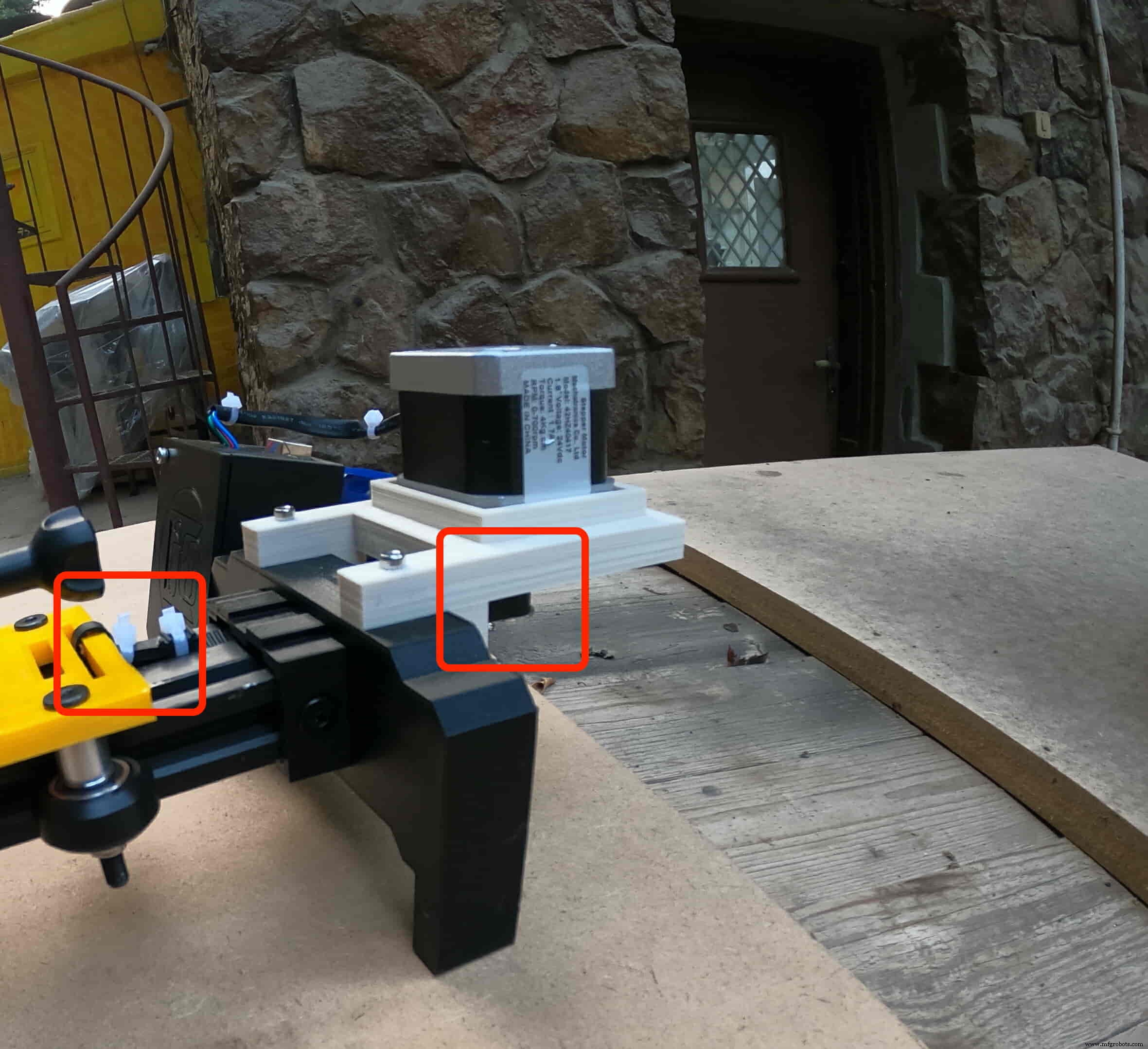
我们需要在其板上安装 NEMA 17 步进电机。然后,使用四颗 M3X16mm 螺丝,我们将把电机固定到位。
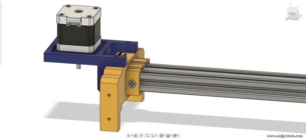
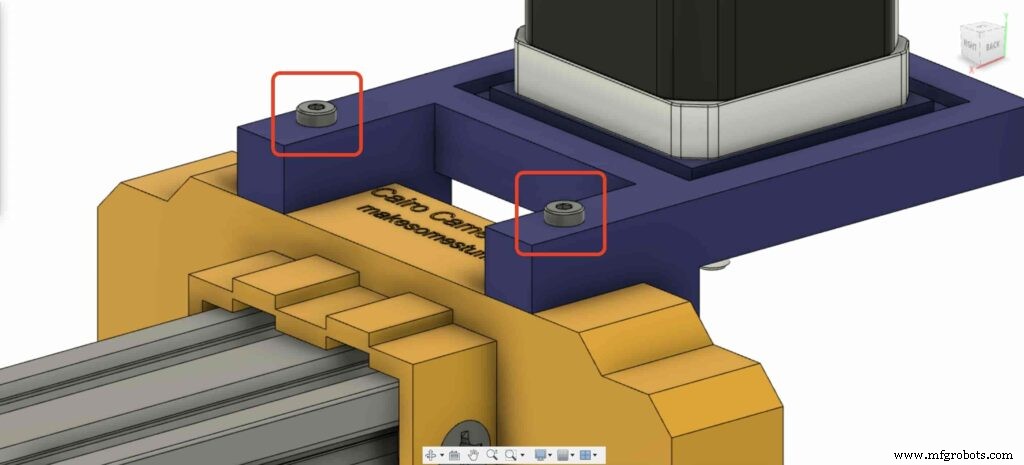
在左腿上,将两个螺母插入左腿顶部螺母处。
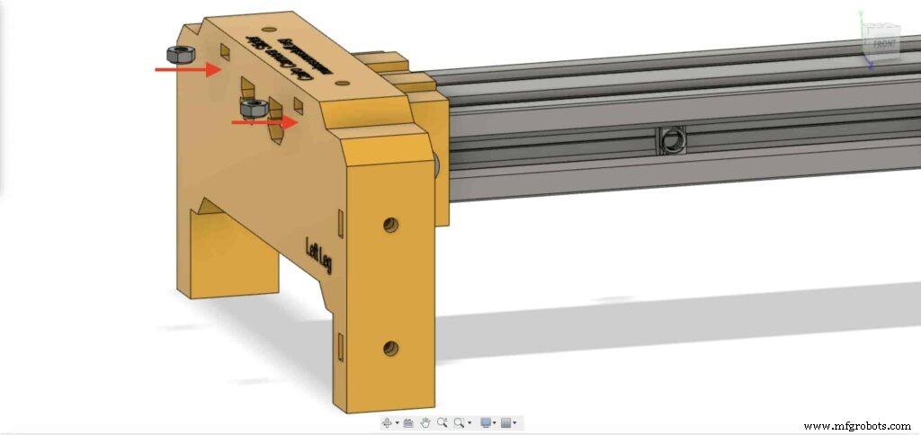
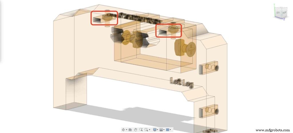
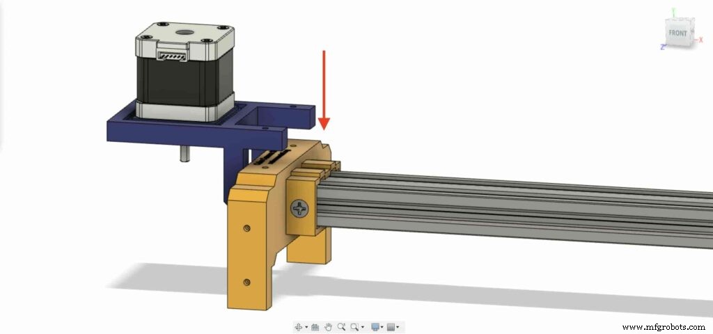
带上 NEMA 17 电机板并将其固定在左腿的顶部。并且,使用两个 M3X16mm 螺丝,我们将把板固定在左腿上。
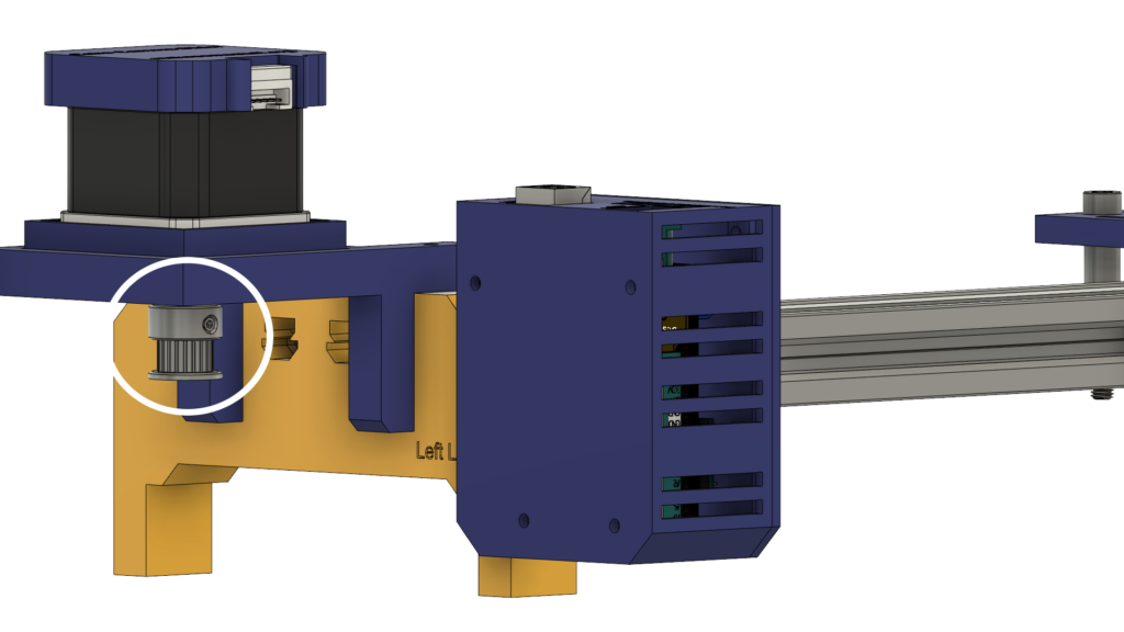
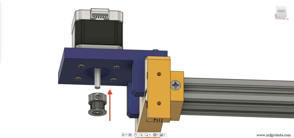
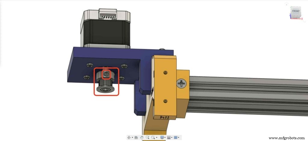
为了能够将步进电机的旋转运动转换为直线运动,我们需要在电机轴上安装一个GT2孔5mm皮带轮。并使用内六角扳手拧紧滑轮固定螺钉以将其固定到位。
让我们去相机滑块右腿,在腿螺母处插入四个M3螺母。
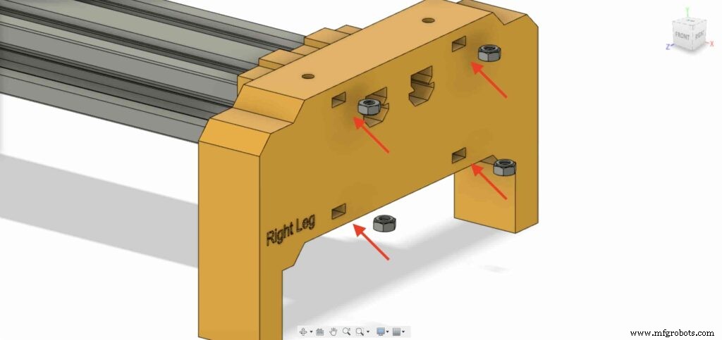
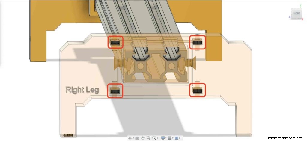
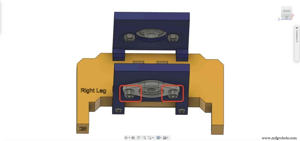
然后,将右腿轴承两块板放在相机滑块右腿的顶部。
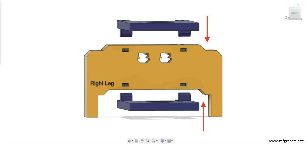
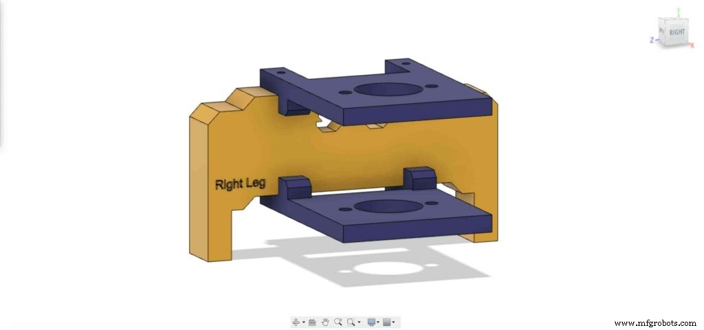
使用四颗 M3X16mm 螺丝,将两块板固定在相机滑块右腿上,使其保持到位。
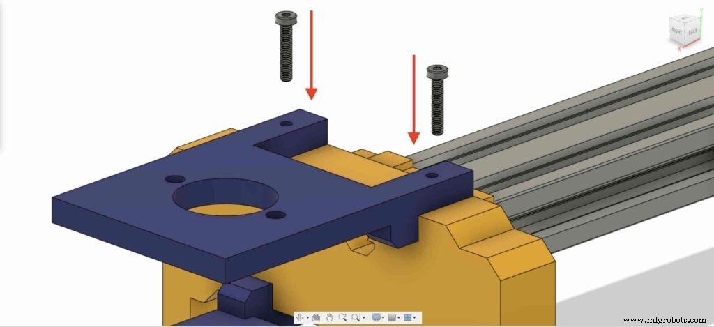
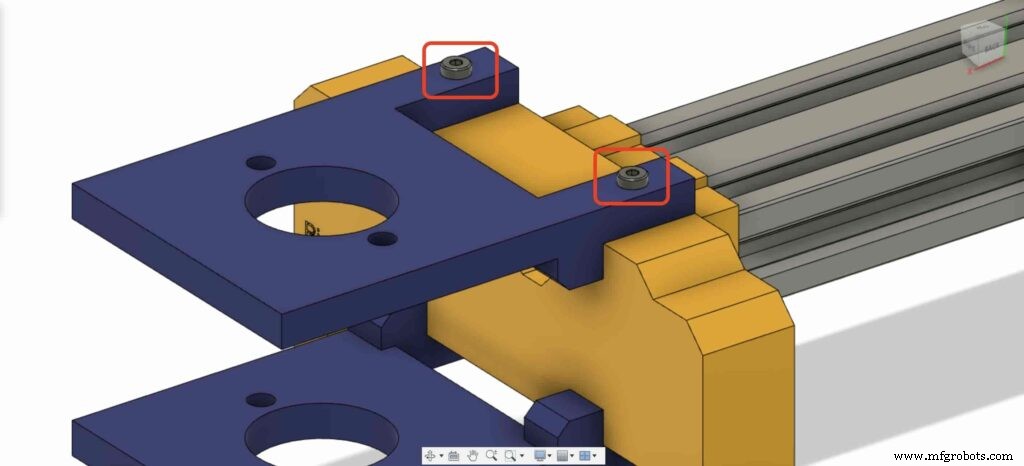
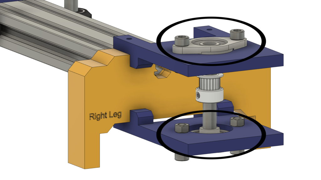
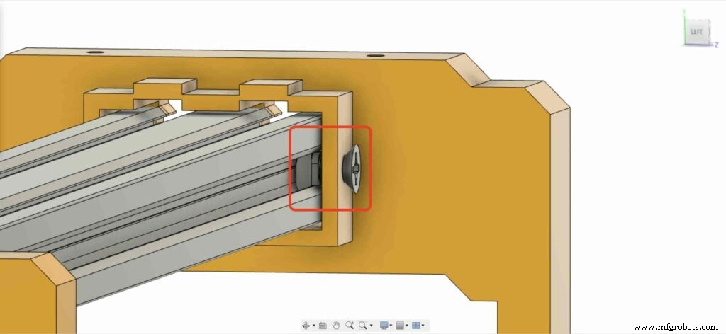
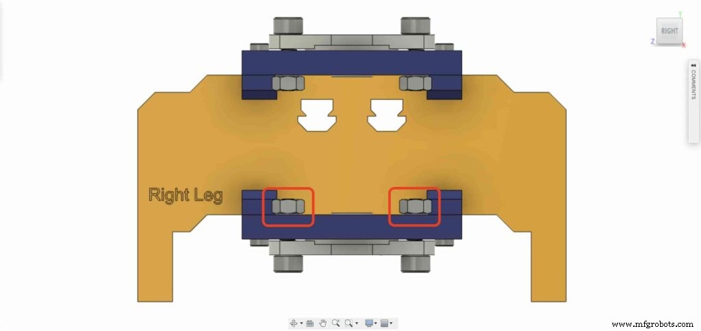
带上一个 8 毫米法兰块轴承并将其安装在右上方的腿板上。使用两个 M5X20mm 螺丝和两个 M5 螺母。
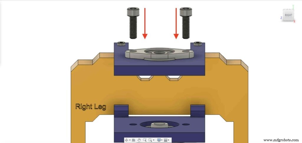
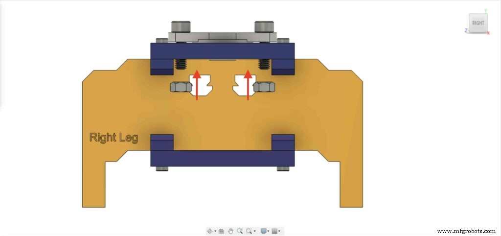
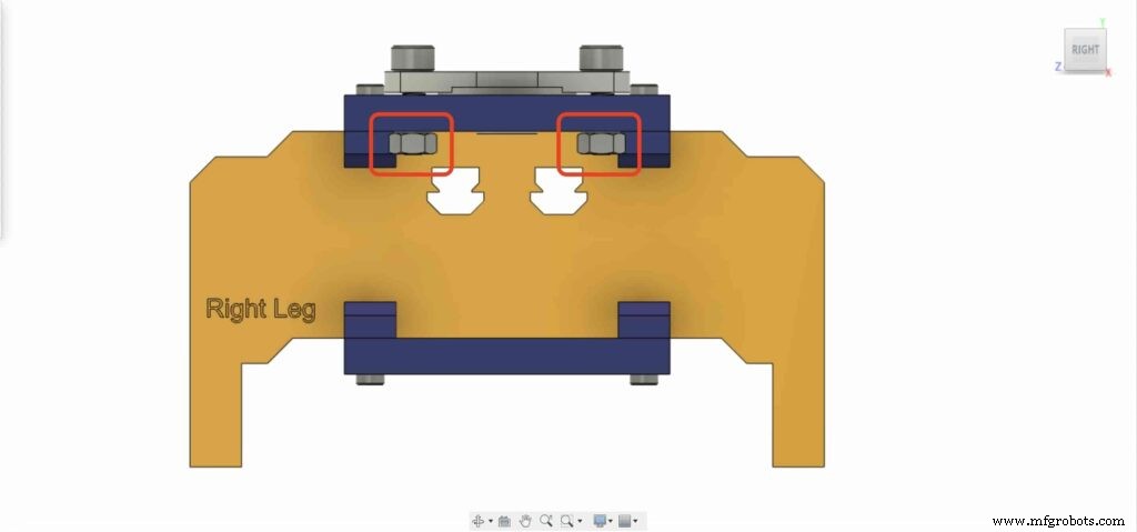
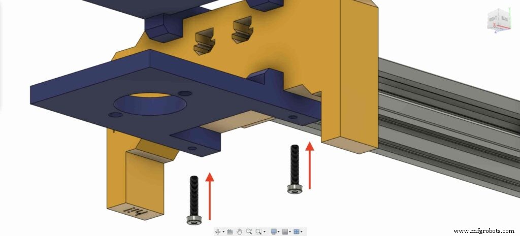
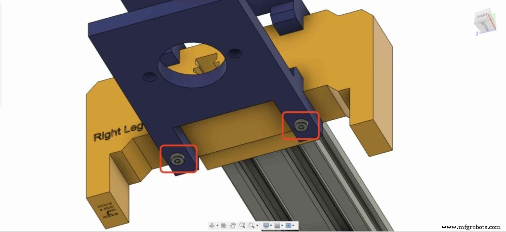
我们需要用第二个8mm法兰轴承块重复上一步将其固定在相机滑块右腿底板上。
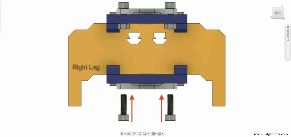
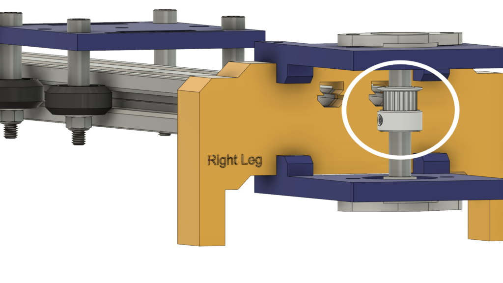
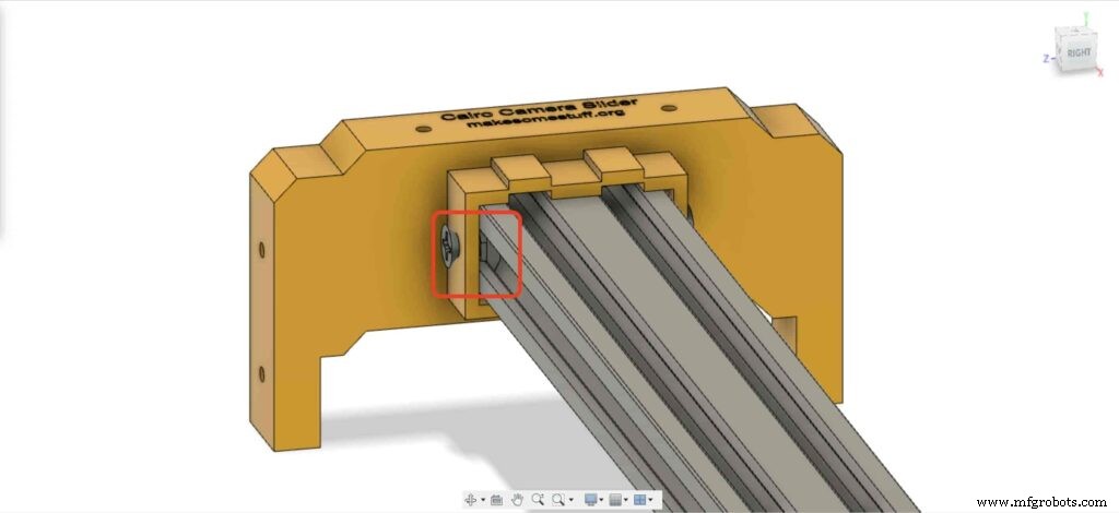
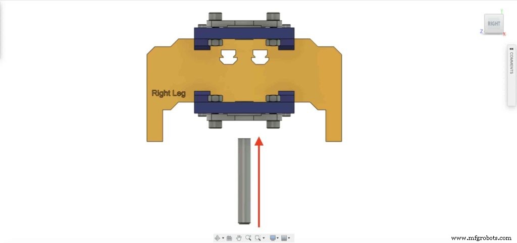
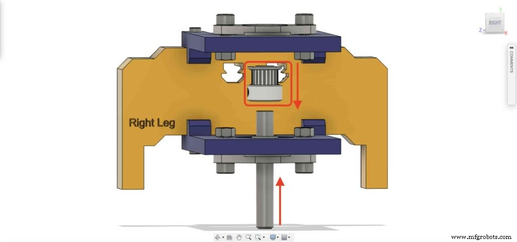
将 8mm 直线导轨轴从底部插入 8mm 法兰轴承座,并将其推到顶部。然后将8mm孔径的滑轮插入直线导轨轴,拧紧滑轮的定位螺丝固定。
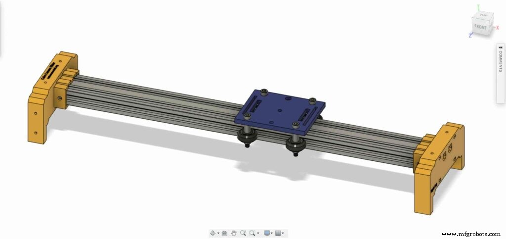
检查点,现在我们组装了所有的相机滑块机制,除了一件事。正时皮带。让我们去做吧。
旋转 NEMA17 电机 5mm 孔皮带轮上的 6mm 同步带。此外,在右腿上有 8 毫米孔滑轮。最后,用相机板收紧腰带。
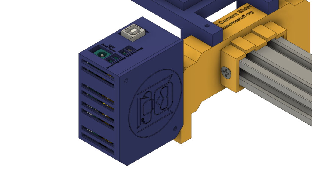
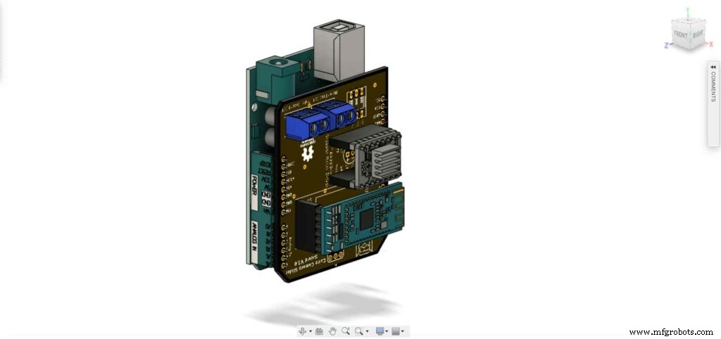
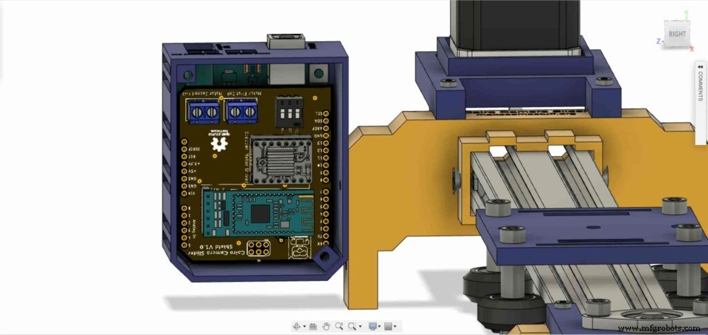
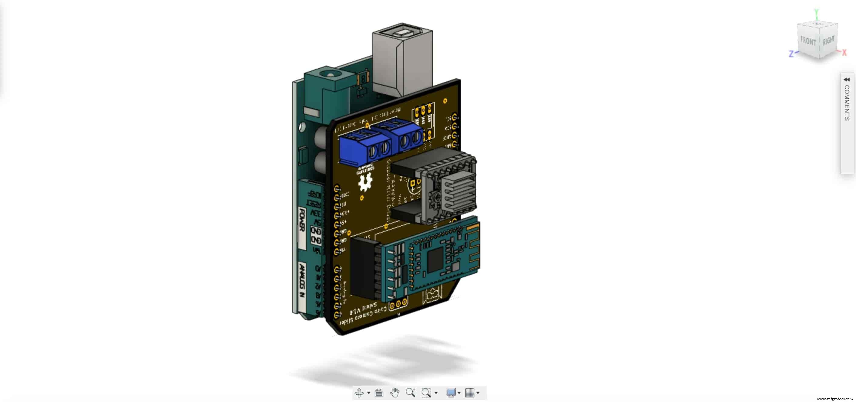
是时候组装控制板了。将 Cairo Camera Slider Arduino 扩展板插入 Arduino 板顶部。
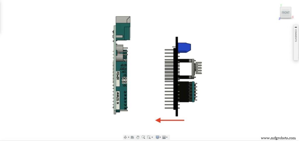
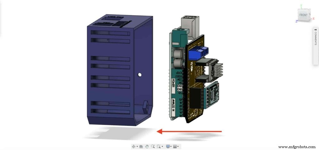
将 Arduino 板和开罗相机滑块护罩插入控制板外壳内。
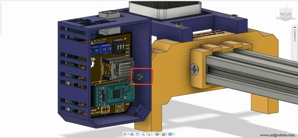
在左腿螺母处插入两个 M3 螺母。
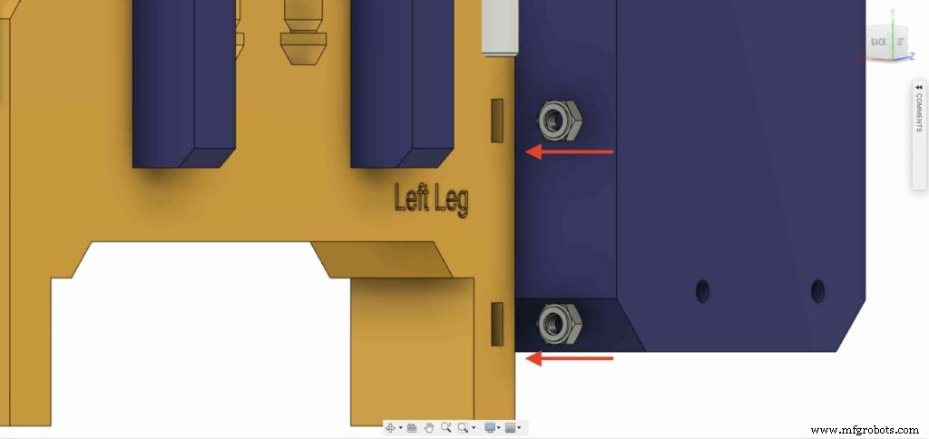
使用 M3X16mm 螺丝将控制板外壳安装到 Cairo Camera Slider 左腿上。

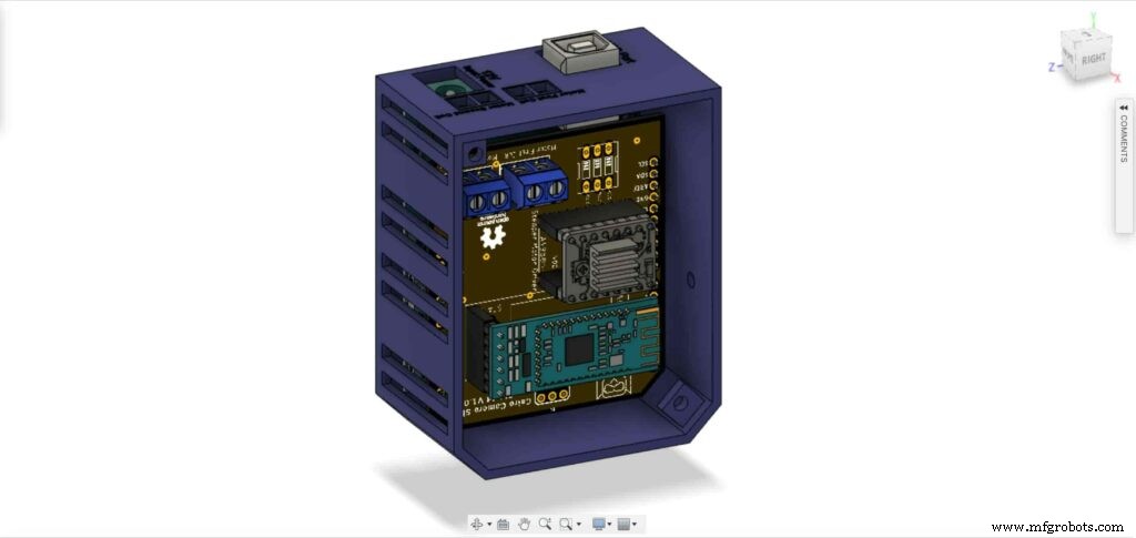
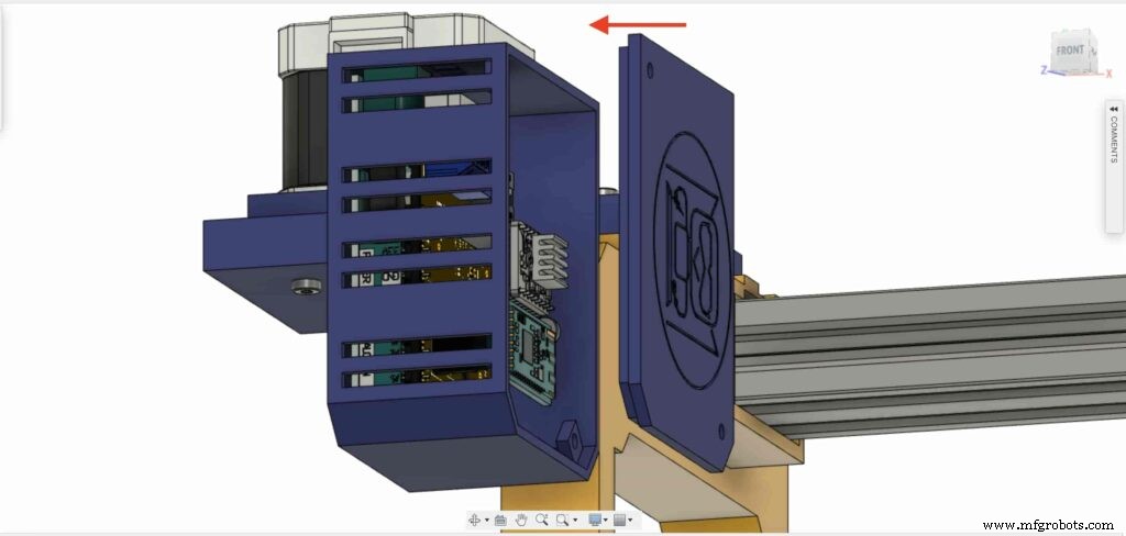
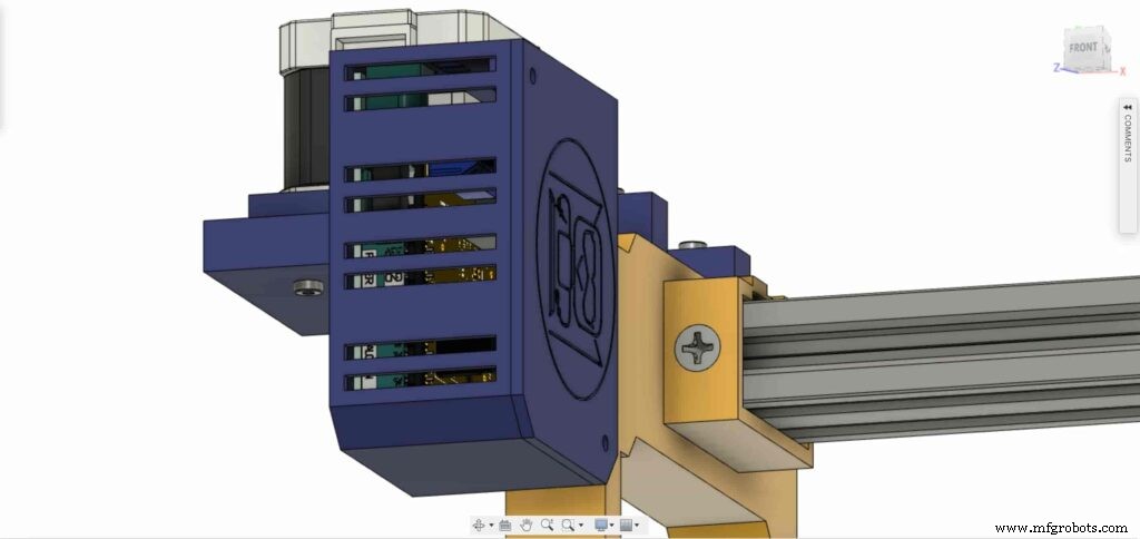
用两个 M3 螺钉和螺母关闭外壳盒顶面,就是这样!

步进电机测试控制
将所有部件组装在一起后,我们需要对其进行测试以确保所有部件都正确安装到位。现在,我们需要通过 A4988 步进电机驱动器将步进电机与 Arduino 板连接起来,并编写一些代码来运行它。
A4988 stepper motor driver
To control any stepper motor using the Arduino board or any microcontroller, you will need a stepper motor driver which works as a translator, takes commands from the Arduino board and translate it to the language that the motor understands.
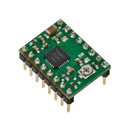
there are a lot of stepper motor drivers out there but we will use the A4988 driver . This driver allows us to control one bipolar motor at up to 2A output current per coil, it’s very simple to interface with the Arduino board you only need two digital pins to fully control your motor step and direction, allows you to control the maximum current output easily with an onboard potentiometer, and gives you a micro-step resolution down to 1/16 micro-step.
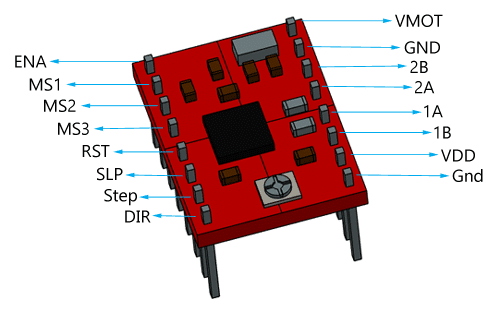
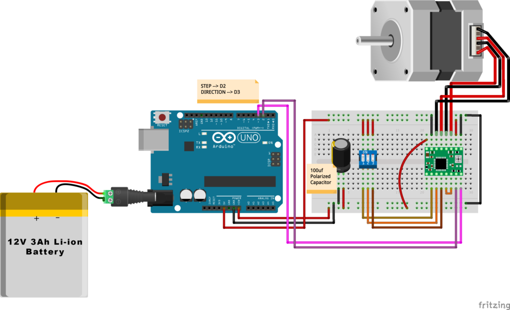
VMOT, GND: It’s the power connection pins for the stepper motor itself, it can be 8V-35V. In our case, we are connecting a 12V 3A power source on those pins with a 100uf decoupling capacitor to protect the A4998 board from any power spikes.
2B, 2A: the output pins for the stepper motor first coil which can deliver up to 2A.
1A, 1B: the output pins for the stepper motor second coil which can deliver up to 2A as well.
VDD, GND: Used for driving the internal logic circuitry, it can be 3V to 5.5V. It’s totally isolated from the VMOT pin.
EN: Stands for “Enable” it’s an active LOW(0V) input pin, which means when this pin pulled LOW(0V) the A4988 chip is enabled. And when pulled HIGH(5V) the A4988 chip is disabled. By default, this pin is pulled LOW(0V). So, the chip is always enabled unless you pull it HIGH(5V).
MS1, MS2, MS3: Through these pins, you can select your motor microstepping resolution(step size). The A4988 gives you five different microstep resolutions (full step, half step, quarter step, Eighth step, Sixteenth step) . By applying appropriate logic levels to these three pins we can set the motors to one of the five step resolutions.
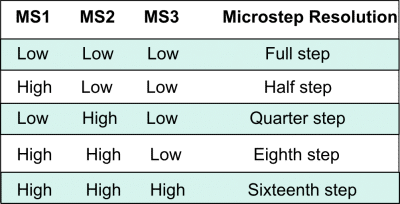
By default, the MS1, MS2, MS3 pins have internal pull-down resistors. So leaving these three microstep selection pins disconnected results in full-step mode.
RST, SLP: The “Reset” pin is an active LOW(0V) input pin, which means when it pulled LOW(0V), all the step inputs are ignored it also resets the translator itself until you pull it HIGH(5V). The “Sleep” pin also an active LOW pin, pulling it LOW, puts the driver in the sleep mode minimizing the power consumption. By default, the “Sleep” pin is pulled HIGH(5V).
STP, DIR: The “Step” pin is responsible for controlling the number of steps that the motor is rotating, each pulse to the “Step” pin corresponds for one microstep in the direction selected by the “Direction” pin, the faster the pulses, the faster the motor will rotate. By applying logic value HIGH(5V) on the “Direction” pin it makes the motor rotate clockwise, by applying LOW(0V) it makes the motor rotate counterclockwise(it may differs from one to another according to your motor wiring with the driver).
NEMA17 Stepper Motor
Stepper motors are DC motors that can rotate in precise increments, they are used in many applications like 3D printers to align the printhead and CNC machines to control the movement of the cutting tool and this is because they are very accurate and precise.
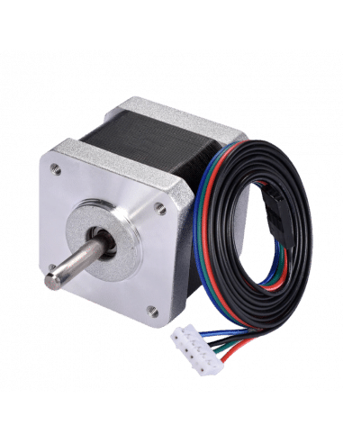
Unlike DC motors, stepper motors are controlled by applying DC electrical pulses to their internal coils. Each pulse makes the shaft advance by one step or a fraction of step which is called “Microstepping”. So, you can control precisely how many steps or even fraction steps you want the motor shaft to move. Another great advantage of using stepper motors is that it can move very precisely and accurately at very slow speeds without even stalling.
The type of motor we are using in this project is the NEMA 17 Bipolar stepper motor . The bipolar stepper motor has two internal coils and it usually has four wires, two wires per coil. unlike the Bipolar stepper motor which has five wires. The “Step Angle” of the motor is 1.8° which indicates how much the shaft advances in each full step, the motor works on 9V but if you want to get the maximum power of it use a 12V power source.
So, by connecting the stepper motor with the A4988 stepper motor driver, we can control how many steps we need the motor to move and in what direction. Also, we can set the “microstep” mode is it full step, half step, quarter step, ….. Let’s take a look at the wiring diagram.
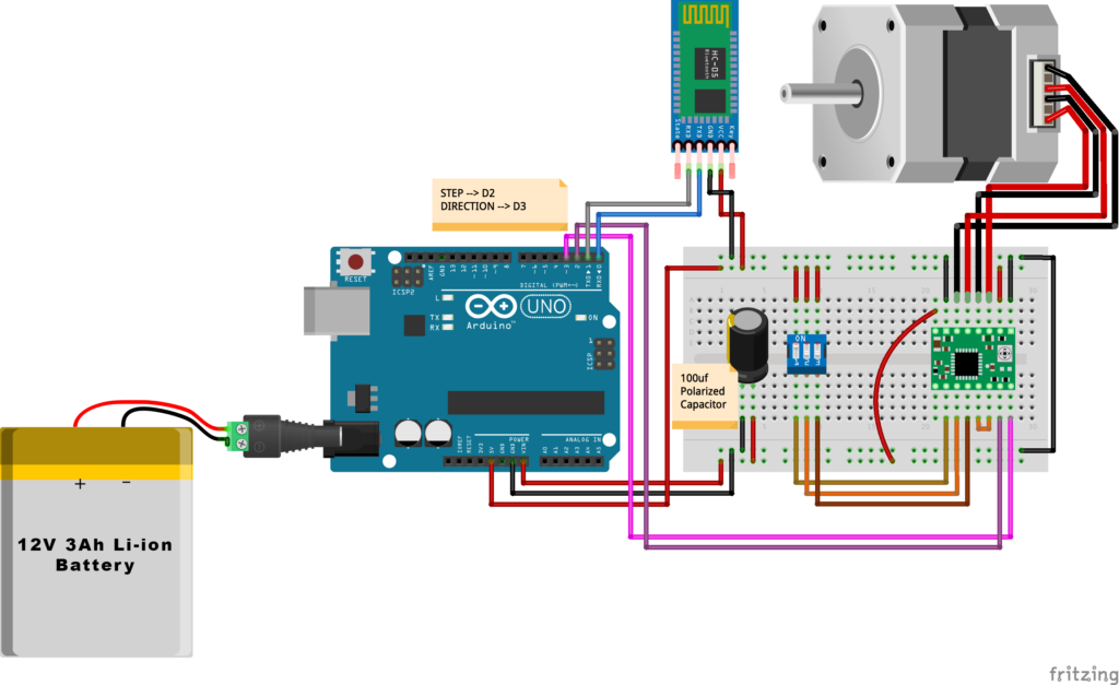
Wiring Diagram
As we stated before, we need to make a small check to make sure that everything we assembled before is right in its place and moving properly. Now, we will wire all the hardware together, the NEMA 17 stepper motor with the A4988 stepper motor driver to the brain, the Arduino board. And using a 12V 3A Lithium-Ion battery to feed the motors with the power it needs.
Arduino Code
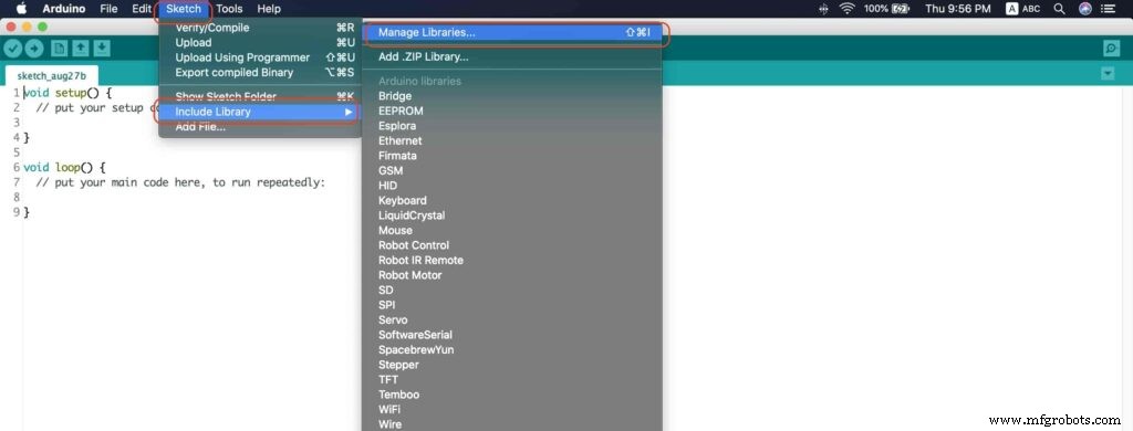
AccelStepper Library Installation
The Installation is pretty simple, we need to open Arduino IDE. From the “Sketch” menu. Select Include Library –> Manage Libraries…
A new window should appear, search for “AccelStepper” and install the library made by “Mike McCauley”. Easy right!
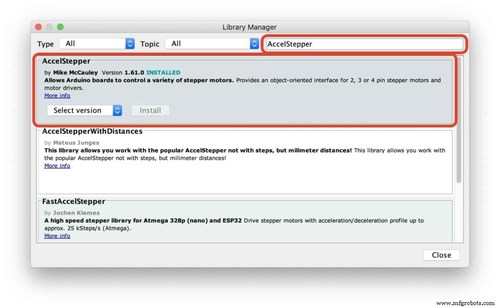
After installing the AccelStepper library, you should see it in the examples menu.
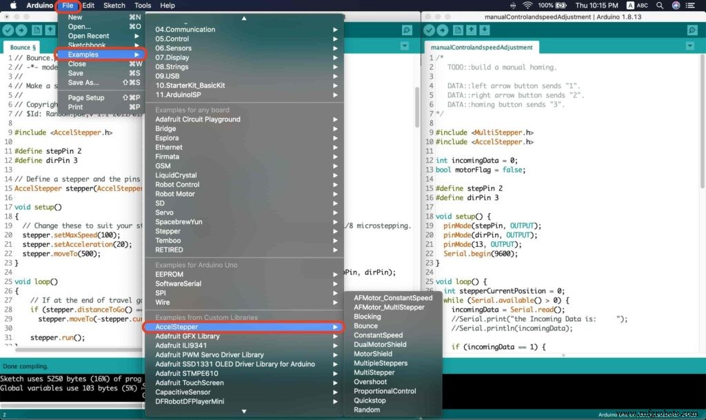
I wanna make sure that the AccelStepper library is installed correctly and my stepper motor connection with the A4988 motor driver is right and my power management is fine. So, let’s write some lines of code to run our stepper motor forward and backward.
// Bounce stepper test program
// Make a single stepper bounce from one limit to another
// Copyright (C) 2020 makesomestuff.org

#include
#define stepPin 2
#define dirPin 3 // Define a stepper and the pins it will use

AccelStepper stepper(AccelStepper::DRIVER, stepPin, dirPin); //create an object. the pin "2" is the step pin, "3" is the direction pin.

void setup()
{
 // Change these to suit your stepper if you want
 stepper.setMaxSpeed(100);
 stepper.setAcceleration(20);
 stepper.moveTo(500);
}

void loop()
{
 // If at the end of travel go to the other end
 if (stepper.distanceToGo() ==0)
 stepper.moveTo(-stepper.currentPosition());
 stepper.run();
}
The code logic is pretty straightforward, we initialized an object from the AccelStepper library, we defined two constants (stepPin, dirPin) that two digital pins is used by the A4988 stepper motor driver to control the movement of the motor itself.
#include

#define stepPin 2
#define dirPin 3 // Define a stepper and the pins it will use

AccelStepper stepper(AccelStepper::DRIVER, stepPin, dirPin); //create an object. the pin "2" is the step pin, "3" is the direction pin.
Inside the void setup function, we set the Max. speed of the stepper motor to 100 steps/sec. Also, we set the acceleration/deceleration rate to 20 steps/sec. lastly, we used the moveTo() function to tell the motor to move 500 steps.
void setup()
{
 // Change these to suit your stepper if you want
 stepper.setMaxSpeed(100);
 stepper.setAcceleration(20);
 stepper.moveTo(500);
}
Inside the void loop function, we are checking if the motor reached it’s position or not. If it reached the position, it will bounce back. and if it didn’t reach it’s position yet, it will keep running.
void loop()
{
 // If at the end of travel go to the other end
 if (stepper.distanceToGo() ==0)
 stepper.moveTo(-stepper.currentPosition());
 stepper.run();
}
Camera Slider Full Wireless Control
We have done great things so far. Let’s continue! The next step after testing everything, is to work on the mobile app that we will use to control the camera slider movement and send the orders to it. Also, we need to work on the Arduino code that will receive the data from the mobile app and according to these data it will take some actions like moving the motor, changing speed, acceleration, and so on…
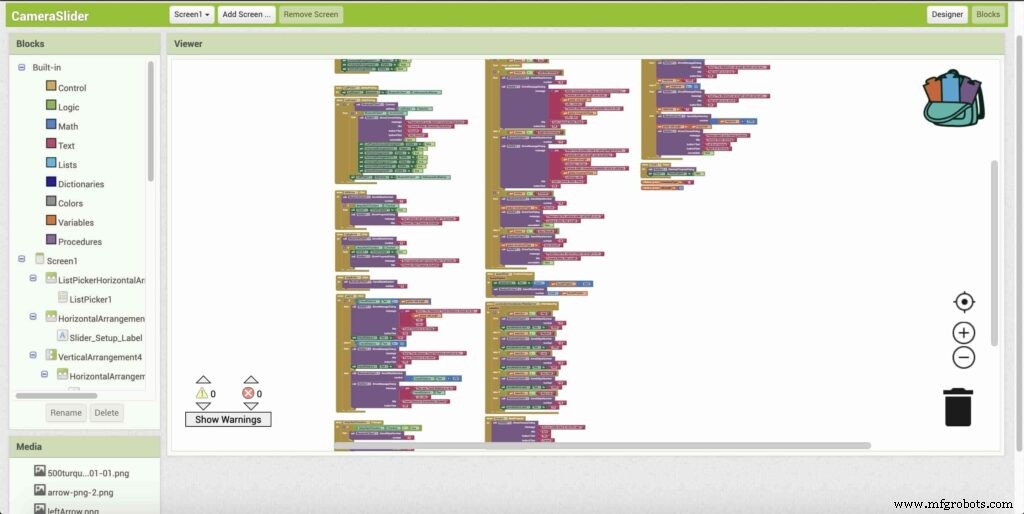
Building The Mobile App
To build the mobile app, I used the MIT App inventor tool that allows you to create mobile apps that run on any Android smartphone. The tool is pretty simple since you only drag and drop some pre-made code blocks to build the logic of your program, also you use some premade blocks to build the app user interface. You can access the source of the mobile app from the link down below. Feel free to edit and share, it’s open-source. Mobile App Source
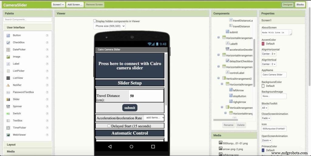
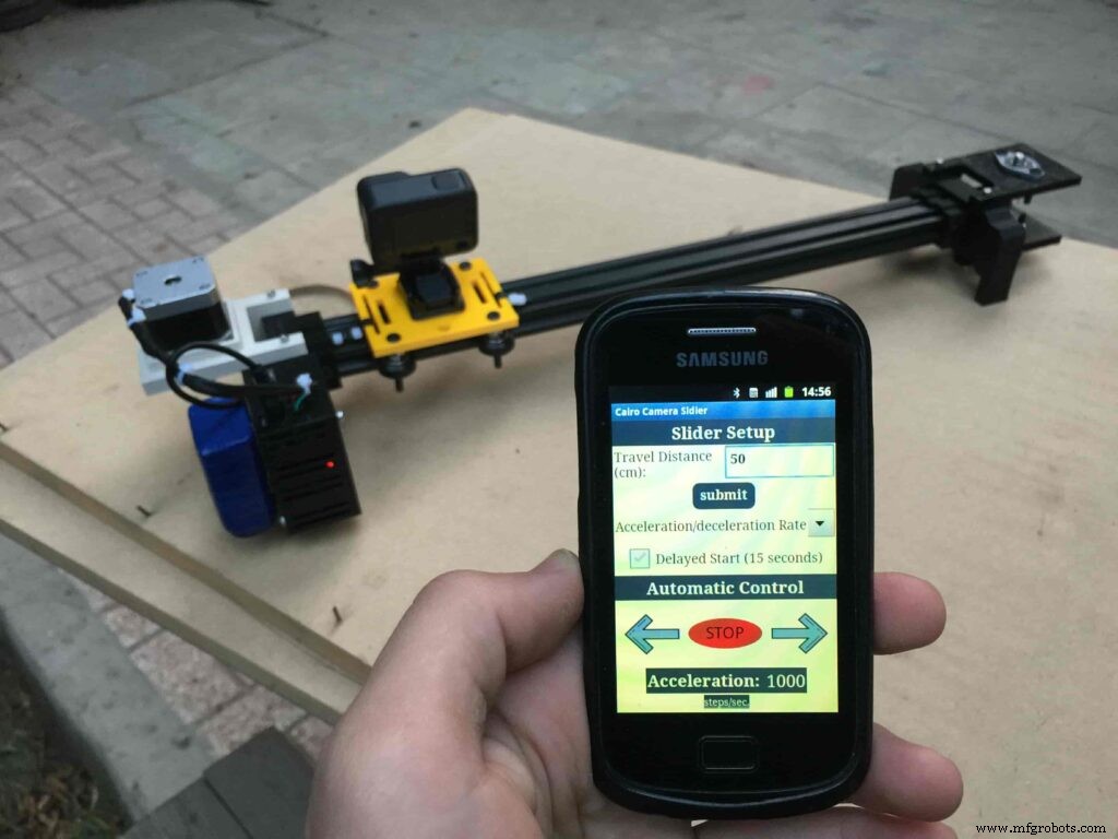
The image down below, a brief explanation for each button function and how it works.
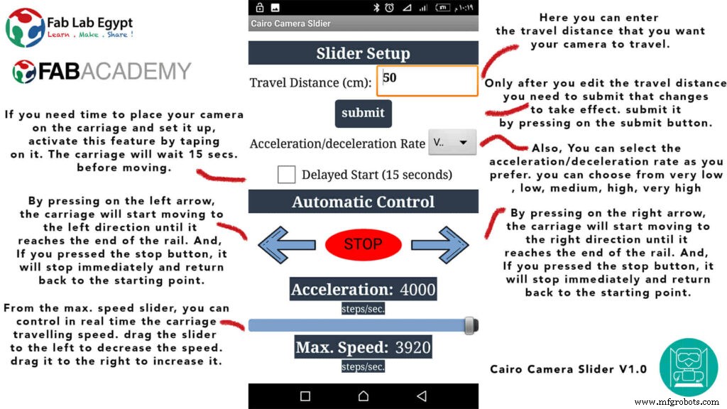
That mobile app will communicate with the Cairo camera slider wirelessly over the Bluetooth communication. So, the next step is to connect a Bluetooth module to the last circuit we built before and upload some lines of code to the Arduino board to be able to establish the communication between the mobile app and the Cairo camera slider.
Wiring Diagram
It’s the time to connect all things together, previously we connected the stepper motor, stepper motor driver, Arduino UNO, and the battery together and tested the circuit and it worked fine. Now, and after building the mobile app, we need to connect the HC-05 Bluetooth module to our circuit.
To make it wireless we will use the HC-05 Bluetooth module which has wide use, it can set as slave or master as well (unlike the HC-06 module which can work only as a slave) which means that you can make a Bluetooth connection between two different Arduino boards. the HC-05 Bluetooth module is an SPP (Serial Port Protocol) module, which means that it communicates with the Arduino board via the Serial communication. You only need to connect the Tx and the Rx pins between the HC-05 module and the Arduino UNO board.
- Tx(Arduino) --> Rx(HC-05)
- Rx(Arduino) --> Tx(HC-05)
- 5V(Arduino) --> VCC(HC-05)
- GNND(Arduino) --> GND(HC-05)
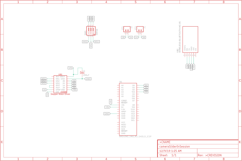
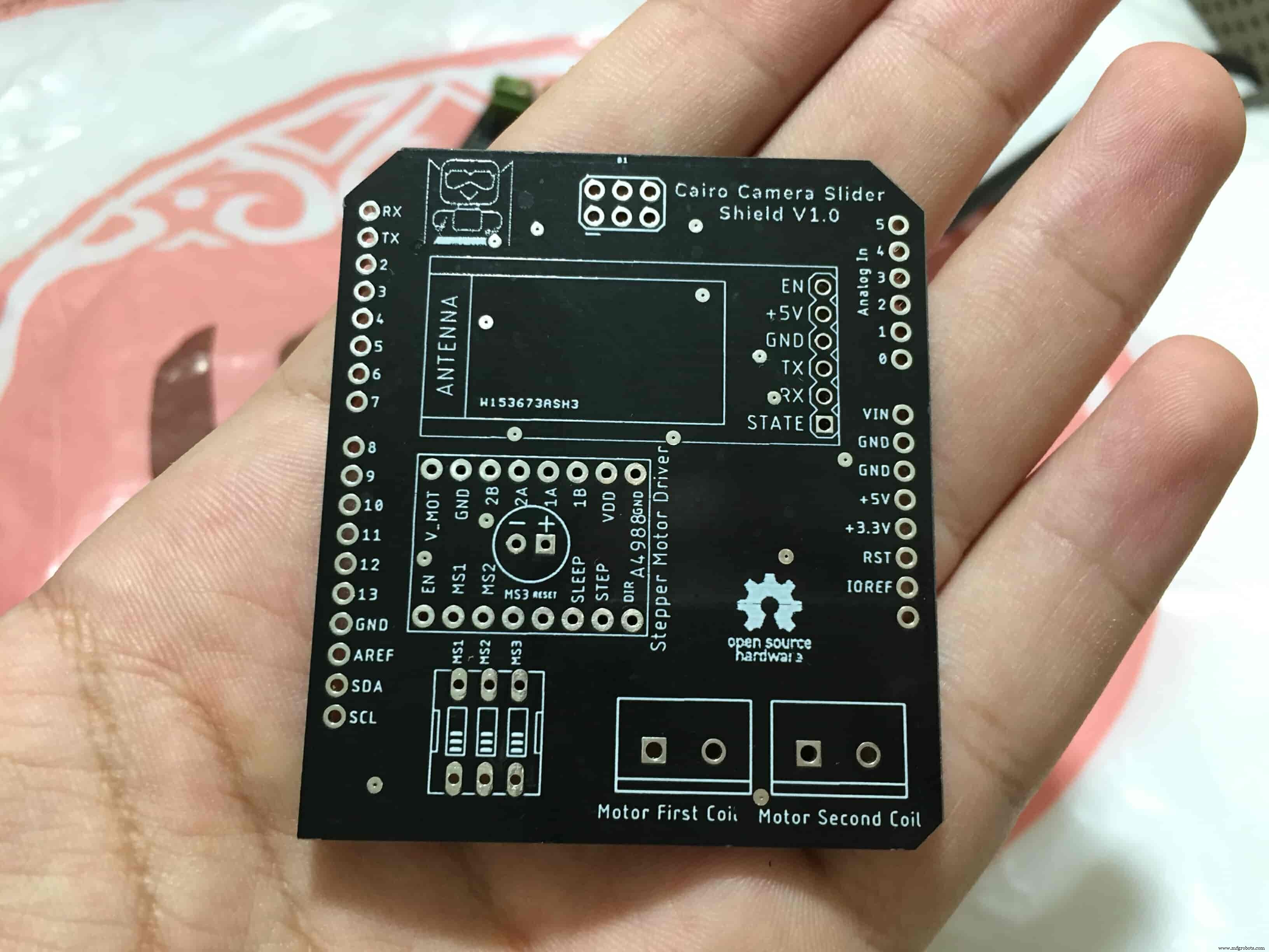
Schematic and PCB Fabrication
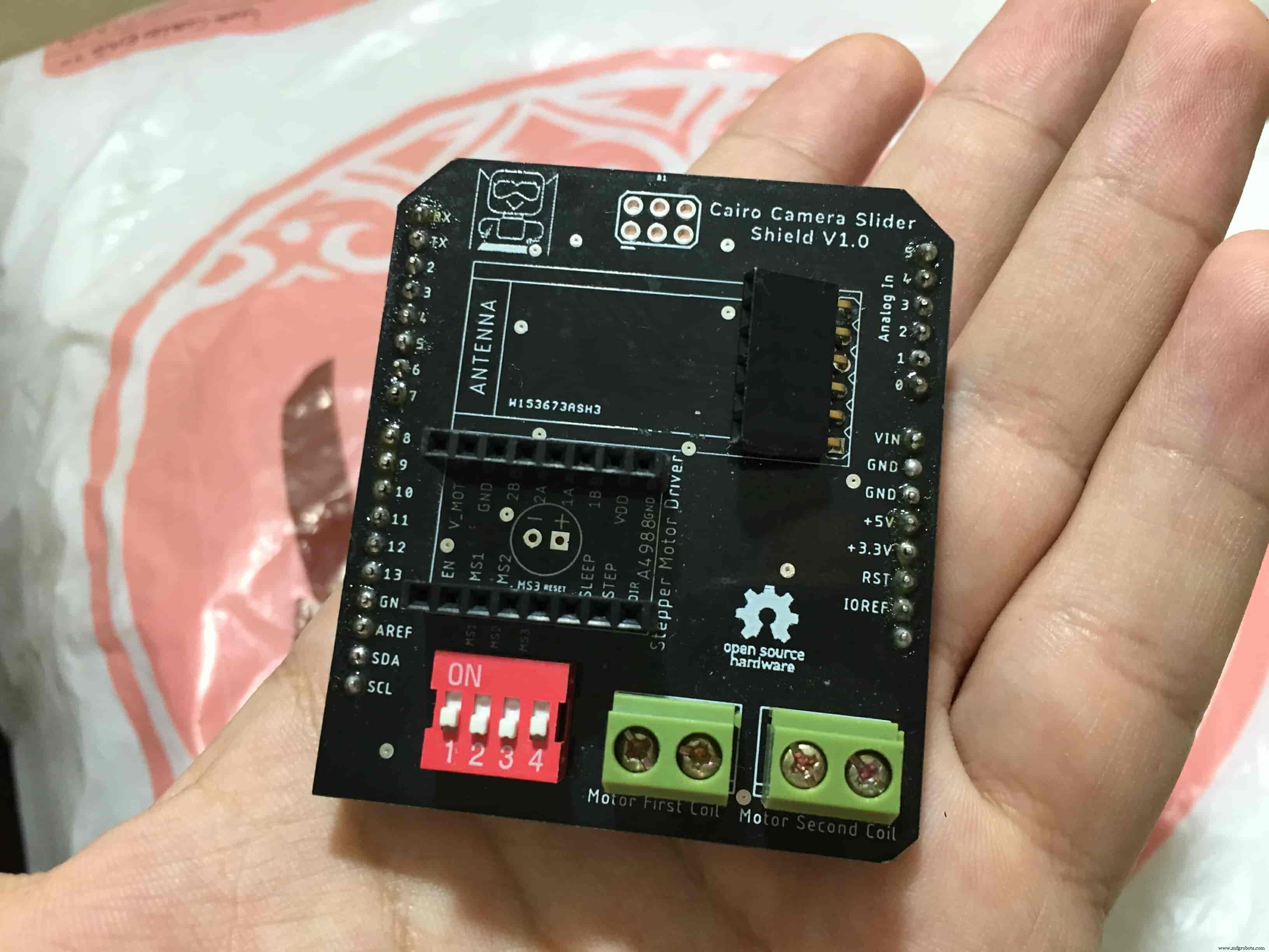
男子! I don’t like breadboarding a big circuit like this. So, I designed a super pretty Arduino UNO shield PCB board that keeps all my components in place without worrying about the jumper wires or even the connections. All you need to do is to place your component on the Arduino shield PCB, insert the HC-05 Bluetooth module, A4988 stepper motor driver, and the battery in their places. and install the shield on top of the Arduino board. that’s it!
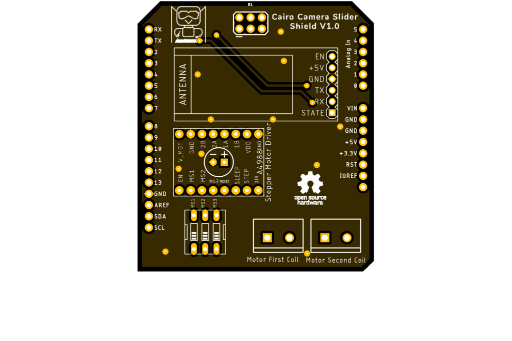
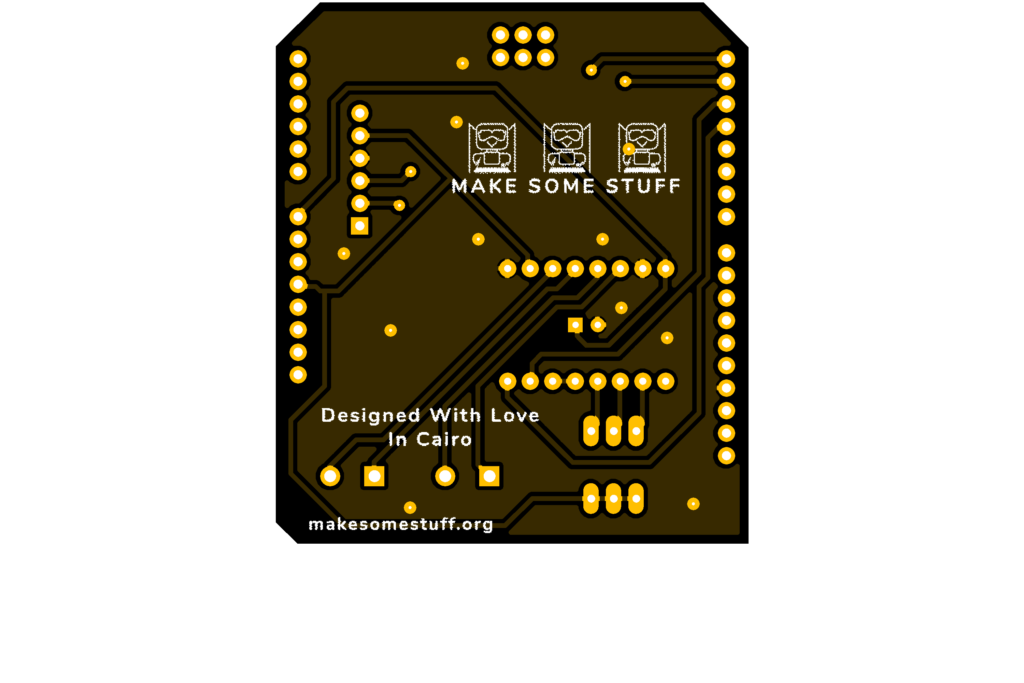
I fabricated my PCB at PCBWay the quality was very good, in a few days the package arrived in Egypt safely. and I paid just 5$ for the fabrication which is amazing. The coolest thing that I was able to check the order fabrication and processing status online on my account panel and track everything happening to my baby board like I was there inside the factory.
you can download the PCB design source files or even ordering the Cairo Camera Slider Arduino Shield PCB from the PCBWay website. PCB Source Files &Ordering

Arduino Code And Bluetooth Communication
/*
 TODO::Update the arduino program to Make the user able to choose the motor driver micro stepping mode. find and equation that helps to automatically adjust the the "steps" variable value.
 TODO::update the mobile app to ask the user on the beginning only about the [homing position(done), microstepping mode].
 TODO::Update the arduino program to make the code only iterates around the "homing position" &"microstepping mode" only once on the void setup() function.

 DATA::left arrow button sends --> 1.
 DATA::right arrow button sends --> 2.
 DATA::stop button sends --> 3.

 DATA::rail length (1cm - 1000cm) --> (201 - 1200).

 DATA::motor acceleration spinner Very High --> 14.
 DATA::motor acceleration spinner High --> 11
 DATA::motor acceleration spinner Medium --> 12
 DATA::motor acceleration spinner Low --> 13
 DATA::motor acceleration spinner Very Low --> 15

 DATA::motor speed slider (1 step/sec. - 4000 step/sec.) --> (5001 - 9000).

 DATA::delay start checkbox is true --> 7.
 DATA::delay start checkbox is false --> 8.

 DATA::left end homing --> 16.
 DATA::right end homing --> 17.

 DATA::Smooth movement Type --> 18.
 DATA::Very Smooth movement Type --> 19.

 1301 --> 2300
*/

#include
#include

#define stepPin 2
#define dirPin 3

bool homingPositionFlag =false;
int startupSetupFlag =0;
bool delayedStart =false;

int incomingData =0;
int movementDistance =50;
long steps =0; //50cm rail by default @1/8 microstepping.
int microStepResolution =0; //4 or 16
long railLength =0;
int sliderSpeed =10;

AccelStepper stepper(AccelStepper::DRIVER, stepPin, dirPin); //create an object. the pin "2" is the step pin, "3" is the direction pin.

void setup() {
 pinMode(stepPin, OUTPUT);
 pinMode(dirPin, OUTPUT);
 Serial.begin(9600);

 stepper.setMaxSpeed(10.00); //The fastest motor speed that can be reliably supported is about 4000 steps per second at a clock frequency of 16 MHz on Arduino such as Uno
 stepper.setAcceleration(500.00); //1600 (40%) (Medium Acceleration rate)

 while (startupSetupFlag <3) {
 if (Serial.available()> 1) {
 unsigned int dataOne =Serial.read();
 unsigned int dataOne1 =Serial.read();
 unsigned int incomingData =(dataOne1 * 256) + dataOne;

 //**************************************************************Motor Homing Part**************************************************
 if (incomingData ==16) { //left end homing position.
 stepper.setCurrentPosition(steps);
 homingPositionFlag =false;
 startupSetupFlag++;
 } else if (incomingData ==17) { //right end homing position.
 stepper.setCurrentPosition(-(steps));
 homingPositionFlag =true;
 startupSetupFlag++;
 }
 //**************************************************************microstep resolution Part**************************************************
 if (incomingData ==18) {
 microStepResolution =4; //50cm rail length @1/4 microstep resolution.
 startupSetupFlag++;
 } else if (incomingData ==19) {
 microStepResolution =16; //50cm rail length @1/16 microstep resolution.
 startupSetupFlag++;
 }

 if (incomingData>=1301 &&incomingData <=2300) {
 railLength =incomingData - 1300; //from raw data to cm.
 if (microStepResolution ==4) {
 steps =((6100L * railLength) / 50L);
 startupSetupFlag++;
 }
 else if (microStepResolution ==16) {
 steps =((25000L * railLength) / 50L);
 startupSetupFlag++;
 }
 }
 }
 //Serial.println(startupSetupFlag);
 }
 /*
 * *********** *********** **********For Debugging Purposes* *********** *********** **********
 Serial.print("rail length:");
 Serial.print(railLength);
 Serial.print(" number of steps:");
 Serial.print(steps);
 Serial.print(" Homing position:");
 Serial.print(stepper.currentPosition());
 Serial.print(" microstep resolution:");
 Serial.println(microStepResolution);*/
}

void loop() {

 if (Serial.available()> 1) {

 unsigned int dataOne =Serial.read();
 unsigned int dataOne1 =Serial.read();
 unsigned int incomingData =(dataOne1 * 256) + dataOne;
 //Serial.print("raw data:");
 //Serial.println(incomingData);

 //**************************************************************Motor Control Part**************************************************
 if (incomingData ==1 &&stepper.isRunning() ==false &&stepper.currentPosition() !=6050 &&homingPositionFlag ==true) {
 if (delayedStart ==true) { //use millis to delay 15 seconds.
 delay(15000); //wait 15 seconds.
 }
 stepper.setCurrentPosition(0);
 stepper.moveTo(steps); //from end to end (@ 1/4 step).
 homingPositionFlag =false;

 /*Serial.print("rail length:");
 Serial.print(railLength);
 Serial.print(" number of steps:");
 Serial.print(steps);
 Serial.print(" Homing position:");
 Serial.print(stepper.currentPosition());
 Serial.print(" microstep resolution:");
 Serial.println(microStepResolution);*/
 }

 else if (incomingData ==2 &&stepper.isRunning() ==false &&stepper.currentPosition() !=-6050 &&homingPositionFlag ==false) {
 if (delayedStart ==true) { //use millis to delay 15 seconds.
 delay(15000); //wait 15 seconds.
 }
 stepper.setCurrentPosition(0);
 stepper.moveTo(-(steps)); //from end to end (@ 1/4 step).
 homingPositionFlag =true;

 /*Serial.print("rail length:");
 Serial.print(railLength);
 Serial.print(" number of steps:");
 Serial.print(steps);
 Serial.print(" Homing position:");
 Serial.print(stepper.currentPosition());
 Serial.print(" microstep resolution:");
 Serial.println(microStepResolution);*/
 }

 else if (incomingData ==3 &&stepper.isRunning() ==true) {
 homing();
 }

 //**************************************************************Set Max. Speed Part**************************************************
 else if (incomingData>=5001 &&incomingData <=9000) {
 sliderSpeed =incomingData - 5000;
 stepper.setMaxSpeed(sliderSpeed);
 }

 //**************************************************************Set Delayed Start Part**************************************************
 else if (incomingData ==7) { //delayed start (15 seconds) is checked "true"
 delayedStart =true;
 }
 else if (incomingData ==8) { //delayed start (15 seconds) is not checked "false"
 delayedStart =false;
 }

 //**************************************************************Set movement distance Part**************************************************
 else if (incomingData>=201 &&incomingData <=1200) { //convertin from rail length into number of steps. (upto 10 meters)
 movementDistance =incomingData - 200; //from raw data to cm.
 if (microStepResolution ==4) {
 steps =((6100L * movementDistance) / 50L);
 }
 else if (microStepResolution ==16) {
 steps =((25000L * movementDistance) / 50L);
 }
 /*Serial.print("rail length:");
 Serial.print(movementDistance);
 Serial.print(" number of steps:");
 Serial.println(steps);*/
 }

 //**************************************************************Set Acceleration Part**************************************************
 else if (incomingData ==11 &&stepper.isRunning() ==false) { //HIGH
 stepper.setAcceleration(3000);
 }

 else if (incomingData ==12 &&stepper.isRunning() ==false) { //Medium
 stepper.setAcceleration(1000);
 }

 else if (incomingData ==13 &&stepper.isRunning() ==false) { //Low
 stepper.setAcceleration(500);
 }

 else if (incomingData ==14 &&stepper.isRunning() ==false) { //Very High
 stepper.setAcceleration(4000);
 }

 else if (incomingData ==15 &&stepper.isRunning() ==false) { //Very Low
 stepper.setAcceleration(10);
 }
 }
 stepper.run();
}

void homing() {
 if (stepper.currentPosition()> 0) {
 homingPositionFlag =true;
 } else {
 homingPositionFlag =false;
 }
 stepper.moveTo(0);
}
Code Logic
We’re using the amazing AccelStepper Arduino library that provides an object-oriented interface for 2, 3, 4 pins stepper motors to control it’s movement precisely.
#define stepPin 2
#define dirPin 3

bool homingPositionFlag =false;

int startupSetupFlag =0;
bool delayedStart =false;

int incomingData =0;
int movementDistance =50;

long steps =0; //50cm rail by default @1/8 microstepping.
int microStepResolution =0; //4 or 16

long railLength =0;
int sliderSpeed =10;

AccelStepper stepper(AccelStepper::DRIVER, stepPin, dirPin); //create an object. the pin "2" is the step pin, "3" is the direction pin.
when you open the mobile app and get connected to the Cairo camera slider it will ask you about the micro-stepping mode that you set the A4988 motor driver to work at. it’s very important to choose the correct micro-stepping mode. The Cairo camera slider only supports the 1/4 and 1/16 micro-step resolution. If you chose a wrong micro-step mode it will affect the distance calculations causing the camera carriage to hit the slider limits. So, be careful!
- 1/4 --> Smooth.
- 1/16 --> Very Smooth.

//**************************************************************microstep resolution Part**************************************************
if (incomingData ==18) {
 microStepResolution =4; //50cm rail length @1/4 microstep resolution.
 startupSetupFlag++;

} else if (incomingData ==19) {
 microStepResolution =16; //50cm rail length @1/16 microstep resolution.
 startupSetupFlag++;
}
It sets the camera slider homing if it’s left or right side homing. the homing position, once you click on right or left side homing a specific piece of data will get sent from the mobile app to the Arduino board according to the homing position that you have chosen.

void setup() {
 pinMode(stepPin, OUTPUT);
 pinMode(dirPin, OUTPUT);
 Serial.begin(9600);

 stepper.setMaxSpeed(10.00); //The fastest motor speed that can be reliably supported is about 4000 steps per second at a clock frequency of 16 MHz on Arduino such as Uno
 stepper.setAcceleration(500.00); //1600 (40%) (Medium Acceleration rate)

 while (startupSetupFlag <3) {
 if (Serial.available()> 1) {
 unsigned int dataOne =Serial.read();
 unsigned int dataOne1 =Serial.read();
 unsigned int incomingData =(dataOne1 * 256) + dataOne;

 //**************************************************************Motor Homing Part**************************************************
 if (incomingData ==16) { //left end homing position.
 stepper.setCurrentPosition(steps);
 homingPositionFlag =false;
 startupSetupFlag++;
 }
 else if (incomingData ==17) { //right end homing position.
 stepper.setCurrentPosition(-(steps));
 homingPositionFlag =true;
 startupSetupFlag++;
 }
now it sets how many steps should the stepper motor moves without hitting the camera carriage with the camera slider right or left legs. it reads and saves the rail length according to the value that the user enters in the mobile app. So, depending on the micro-step resolution that the user selected before, and the rail length I can calculate the number of steps that the motor should rotate to reach the limits of the slider rail without hitting the right or left legs.

if (incomingData>=1301 &&incomingData <=2300) {
 railLength =incomingData - 1300; //from raw data to cm.
 if (microStepResolution ==4) {
 steps =((6100L * railLength) / 50L);
 startupSetupFlag++;
 }
 else if (microStepResolution ==16) {
 steps =((25000L * railLength) / 50L);
 startupSetupFlag++;
 }
 }
 }
 //Serial.println(startupSetupFlag);
 }
inside the loop function, it reads the mobile app incoming data and according to these data it takes different actions, like moving the stepper motor clockwise, moving anti-clockwise, stop and return back to the starting point, and changing the traveling speed, so on…
void loop() {

 if (Serial.available()> 1) {

 unsigned int dataOne =Serial.read();
 unsigned int dataOne1 =Serial.read();
 unsigned int incomingData =(dataOne1 * 256) + dataOne;
 //Serial.print("raw data:");
 //Serial.println(incomingData);

 //**************************************************************Motor Control Part**************************************************
 if (incomingData ==1 &&stepper.isRunning() ==false &&stepper.currentPosition() !=6050 &&homingPositionFlag ==true) {
 if (delayedStart ==true) { //use millis to delay 15 seconds.
 delay(15000); //wait 15 seconds.
 }
 stepper.setCurrentPosition(0);
 stepper.moveTo(steps); //from end to end (@ 1/4 step).
 homingPositionFlag =false;

 /*Serial.print("rail length:");
 Serial.print(railLength);
 Serial.print(" number of steps:");
 Serial.print(steps);
 Serial.print(" Homing position:");
 Serial.print(stepper.currentPosition());
 Serial.print(" microstep resolution:");
 Serial.println(microStepResolution);*/
 }

 else if (incomingData ==2 &&stepper.isRunning() ==false &&stepper.currentPosition() !=-6050 &&homingPositionFlag ==false) {
 if (delayedStart ==true) { //use millis to delay 15 seconds.
 delay(15000); //wait 15 seconds.
 }
 stepper.setCurrentPosition(0);
 stepper.moveTo(-(steps)); //from end to end (@ 1/4 step).
 homingPositionFlag =true;

 /*Serial.print("rail length:");
 Serial.print(railLength);
 Serial.print(" number of steps:");
 Serial.print(steps);
 Serial.print(" Homing position:");
 Serial.print(stepper.currentPosition());
 Serial.print(" microstep resolution:");
 Serial.println(microStepResolution);*/
 }

 else if (incomingData ==3 &&stepper.isRunning() ==true) {
 homing();
 }

 //**************************************************************Set Max. Speed Part**************************************************
 else if (incomingData>=5001 &&incomingData <=9000) {
 sliderSpeed =incomingData - 5000;
 stepper.setMaxSpeed(sliderSpeed);
 }

 //**************************************************************Set Delayed Start Part**************************************************
 else if (incomingData ==7) { //delayed start (15 seconds) is checked "true"
 delayedStart =true;
 }
 else if (incomingData ==8) { //delayed start (15 seconds) is not checked "false"
 delayedStart =false;
 }

 //**************************************************************Set movement distance Part**************************************************
 else if (incomingData>=201 &&incomingData <=1200) { //convertin from rail length into number of steps. (upto 10 meters)
 movementDistance =incomingData - 200; //from raw data to cm.
 if (microStepResolution ==4) {
 steps =((6100L * movementDistance) / 50L);
 }
 else if (microStepResolution ==16) {
 steps =((25000L * movementDistance) / 50L);
 }
 /*Serial.print("rail length:");
 Serial.print(movementDistance);
 Serial.print(" number of steps:");
 Serial.println(steps);*/
 }

 //**************************************************************Set Acceleration Part**************************************************
 else if (incomingData ==11 &&stepper.isRunning() ==false) { //HIGH
 stepper.setAcceleration(3000);
 }

 else if (incomingData ==12 &&stepper.isRunning() ==false) { //Medium
 stepper.setAcceleration(1000);
 }

 else if (incomingData ==13 &&stepper.isRunning() ==false) { //Low
 stepper.setAcceleration(500);
 }

 else if (incomingData ==14 &&stepper.isRunning() ==false) { //Very High
 stepper.setAcceleration(4000);
 }

 else if (incomingData ==15 &&stepper.isRunning() ==false) { //Very Low
 stepper.setAcceleration(10);
 }
 }
 stepper.run();
}

void homing() {
 if (stepper.currentPosition()> 0) {
 homingPositionFlag =true;
 } else {
 homingPositionFlag =false;
 }
 stepper.moveTo(0);
}
Cairo Camera Slider User Guide &troubleshooting
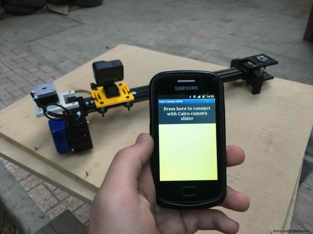
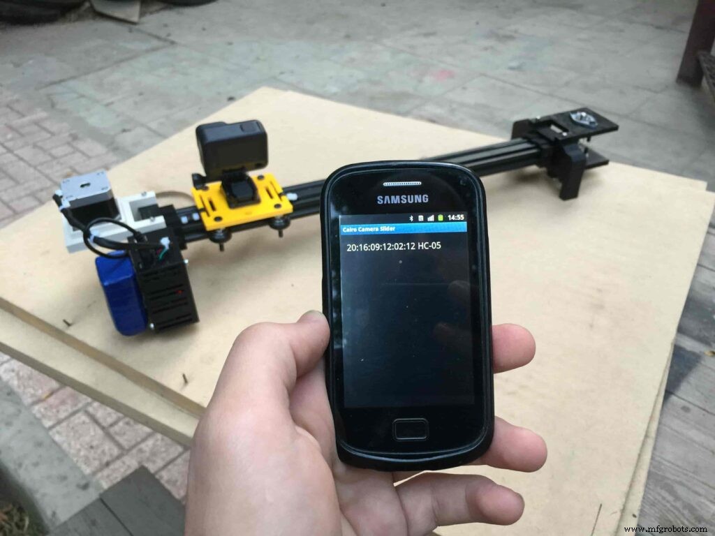
After connecting the 12V power source to the Arduino UNO board that distributes power to the Cairo camera slider Arduino shield as well, turn on the Bluetooth on your mobile, search for new devices, pair with the HC-05 device, and open the mobile app then press on the “Press here to connect with Cairo camera slider” button. It will show up the menu of the paired Bluetooth devices, select the HC-05 Bluetooth device.
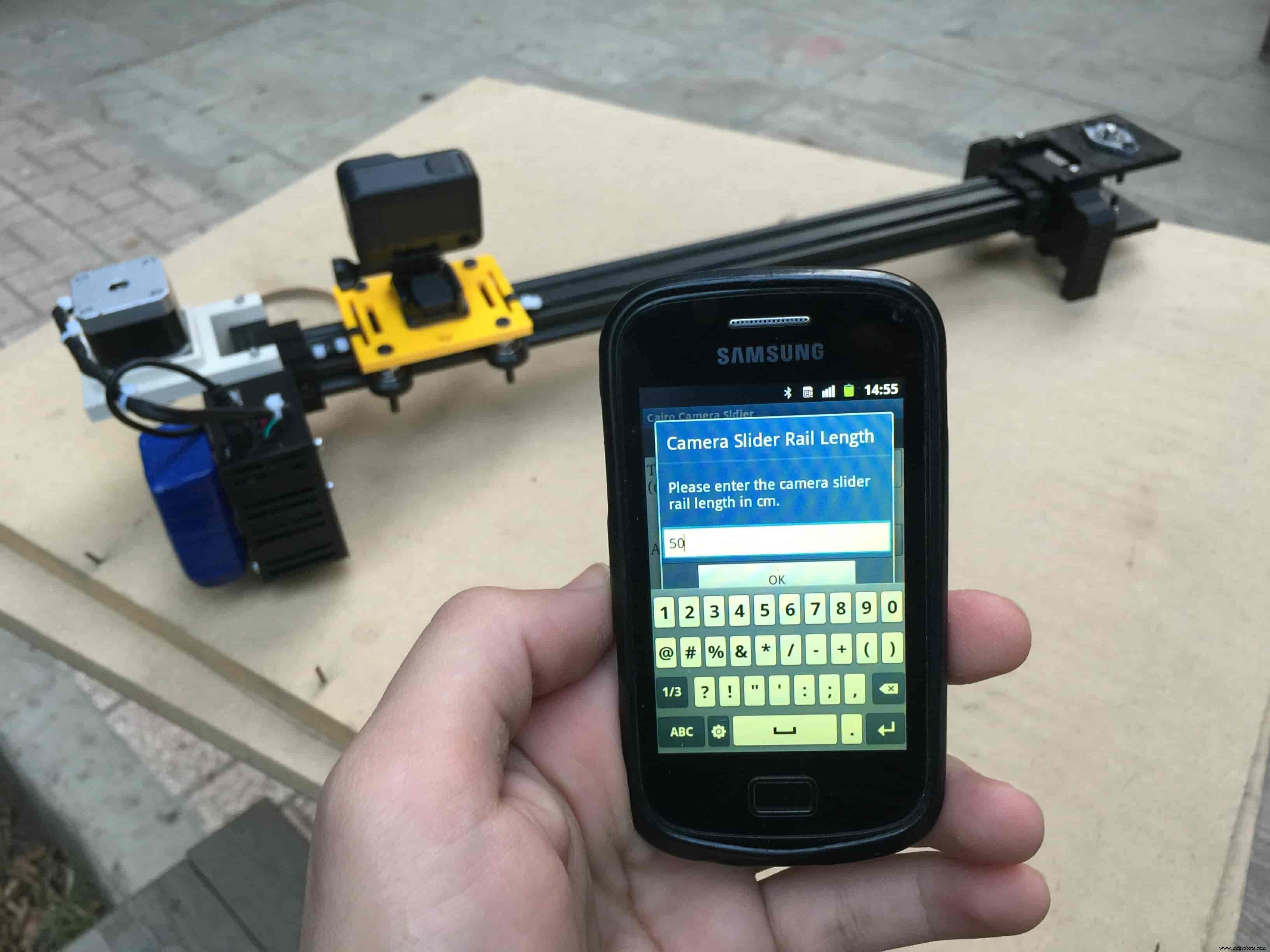
After connecting successfully with the Control board, the mobile app will ask you some questions to set up some parameters. First question will ask you about the micro-step resolution of the stepper motor driver if it’s smooth(1/4 micro-step), or very smooth(1/16 micro-step). select the mode According to the micro-stepping resolution mode that you set the A4988 driver at. If you selected a wrong mode The Cairo camera slider will not work correctly.
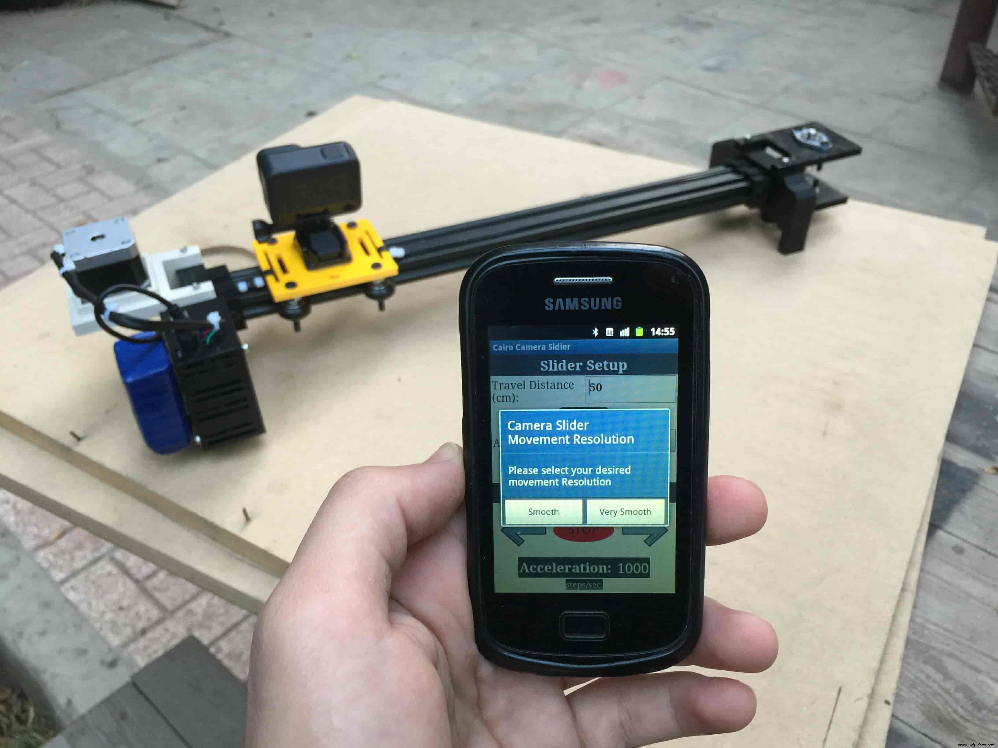
Then, it will ask you about the aluminum rail length that you are using in your camera slider. Enter the distance in CM. in my case I’m using a 50cm rail length.
Lastly, it will ask you about the camera carriage homing position, It’s very important to place the camera carriage on one of the two rail ends, the right end or the left end. In my case, the camera carriage is on the left end. So, I selected the left end homing.
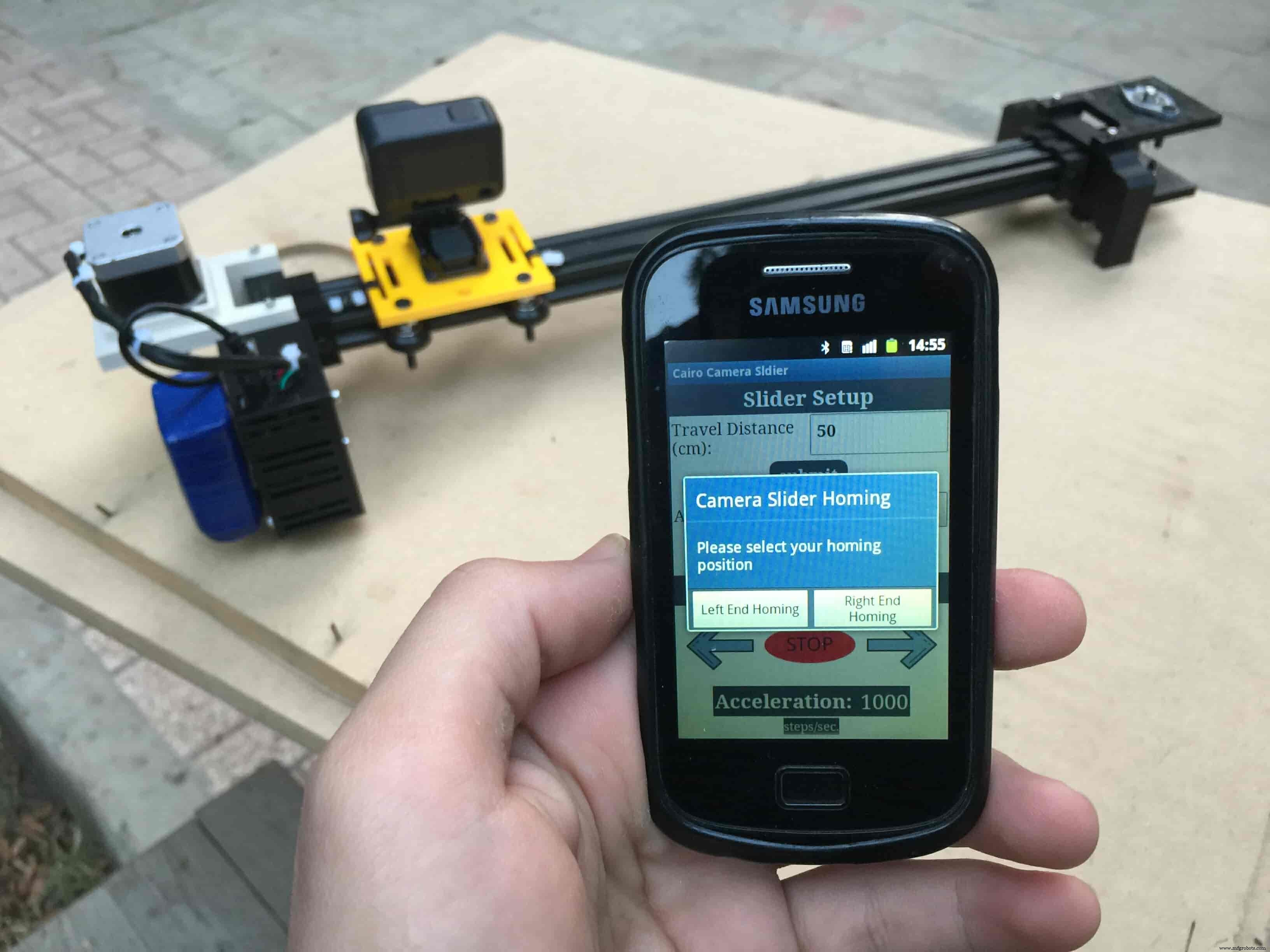
If you started the Cairo camera slider and the camera carriage is on the middle of the rail or not on one of the two rail ends it will cause the carriage to hit the limits when it moves.
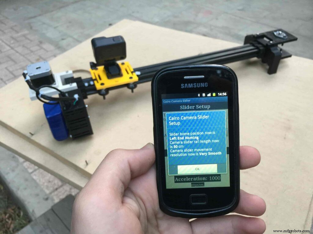
After you finish the set-up process, It will show you the parameters that you have set. And once you click OK, you will be ready to play around with your lovely Cairo camera slider.
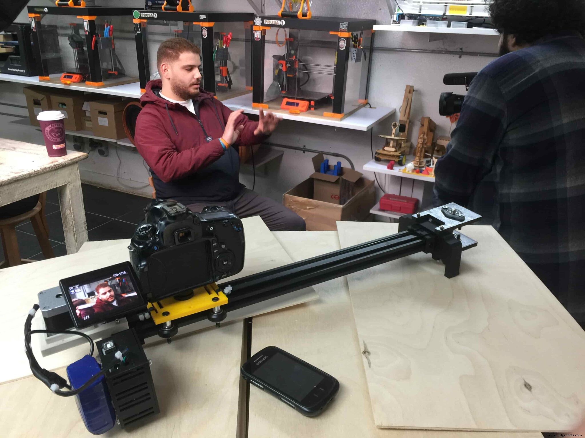
Cairo Camera Slider In-Action
Code
- Cairo Camera Slider Final Code
Cairo Camera Slider Final CodeArduino
/* TODO::Update the arduino program to Make the user able to choose the motor driver micro stepping mode. find and equation that helps to automatically adjust the the "steps" variable value. TODO::update the mobile app to ask the user on the beginning only about the [homing position(done), microstepping mode]. TODO::Update the arduino program to make the code only iterates around the "homing position" &"microstepping mode" only once on the void setup() function. DATA::left arrow button sends --> 1. DATA::right arrow button sends --> 2. DATA::stop button sends --> 3. DATA::rail length (1cm - 1000cm) --> (201 - 1200). DATA::motor acceleration spinner Very High --> 14. DATA::motor acceleration spinner High --> 11 DATA::motor acceleration spinner Medium --> 12 DATA::motor acceleration spinner Low --> 13 DATA::motor acceleration spinner Very Low --> 15 DATA::motor speed slider (1 step/sec. - 4000 step/sec.) --> (5001 - 9000). DATA::delay start checkbox is true --> 7. DATA::delay start checkbox is false --> 8. DATA::left end homing --> 16. DATA::right end homing --> 17. DATA::Smooth movement Type --> 18. DATA::Very Smooth movement Type --> 19. 1301 --> 2300*/#include#include #define stepPin 2#define dirPin 3bool homingPositionFlag =false;int startupSetupFlag =0;bool delayedStart =false;int incomingData =0;int movementDistance =50;long steps =0; //50cm rail by default @1/8 microstepping.int microStepResolution =0; //4 or 16long railLength =0;int sliderSpeed =10;AccelStepper stepper(AccelStepper::DRIVER, stepPin, dirPin); //create an object. the pin "2" is the step pin, "3" is the direction pin.void setup() { pinMode(stepPin, OUTPUT); pinMode(dirPin, OUTPUT); Serial.begin(9600); stepper.setMaxSpeed(10.00); //The fastest motor speed that can be reliably supported is about 4000 steps per second at a clock frequency of 16 MHz on Arduino such as Uno stepper.setAcceleration(500.00); //1600 (40%) (Medium Acceleration rate) while (startupSetupFlag <3) { if (Serial.available()> 1) { unsigned int dataOne =Serial.read(); unsigned int dataOne1 =Serial.read(); unsigned int incomingData =(dataOne1 * 256) + dataOne; //**************************************************************Motor Homing Part************************************************** if (incomingData ==16) { //left end homing position. stepper.setCurrentPosition(steps); homingPositionFlag =false; startupSetupFlag++; } else if (incomingData ==17) { //right end homing position. stepper.setCurrentPosition(-(steps)); homingPositionFlag =true; startupSetupFlag++; } //**************************************************************microstep resolution Part************************************************** if (incomingData ==18) { microStepResolution =4; //50cm rail length @1/4 microstep resolution. startupSetupFlag++; } else if (incomingData ==19) { microStepResolution =16; //50cm rail length @1/16 microstep resolution. startupSetupFlag++; } if (incomingData>=1301 &&incomingData <=2300) { railLength =incomingData - 1300; //from raw data to cm. if (microStepResolution ==4) { steps =((6100L * railLength) / 50L); startupSetupFlag++; } else if (microStepResolution ==16) { steps =((25000L * railLength) / 50L); startupSetupFlag++; } } } //Serial.println(startupSetupFlag); } /* * *********** *********** **********For Debugging Purposes* *********** *********** ********** Serial.print("rail length:"); Serial.print(railLength); Serial.print(" number of steps:"); Serial.print(steps); Serial.print(" Homing position:"); Serial.print(stepper.currentPosition()); Serial.print(" microstep resolution:"); Serial.println(microStepResolution);*/}void loop() { if (Serial.available()> 1) { unsigned int dataOne =Serial.read(); unsigned int dataOne1 =Serial.read(); unsigned int incomingData =(dataOne1 * 256) + dataOne; //Serial.print("raw data:"); //Serial.println(incomingData); //**************************************************************Motor Control Part************************************************** if (incomingData ==1 &&stepper.isRunning() ==false &&stepper.currentPosition() !=6050 &&homingPositionFlag ==true) { if (delayedStart ==true) { //use millis to delay 15 seconds. delay(15000); //wait 15 seconds. } stepper.setCurrentPosition(0); stepper.moveTo(steps); //from end to end (@ 1/4 step). homingPositionFlag =false; /*Serial.print("rail length:"); Serial.print(railLength); Serial.print(" number of steps:"); Serial.print(steps); Serial.print(" Homing position:"); Serial.print(stepper.currentPosition()); Serial.print(" microstep resolution:"); Serial.println(microStepResolution);*/ } else if (incomingData ==2 &&stepper.isRunning() ==false &&stepper.currentPosition() !=-6050 &&homingPositionFlag ==false) { if (delayedStart ==true) { //use millis to delay 15 seconds. delay(15000); //wait 15 seconds. } stepper.setCurrentPosition(0); stepper.moveTo(-(steps)); //from end to end (@ 1/4 step). homingPositionFlag =true; /*Serial.print("rail length:"); Serial.print(railLength); Serial.print(" number of steps:"); Serial.print(steps); Serial.print(" Homing position:"); Serial.print(stepper.currentPosition()); Serial.print(" microstep resolution:"); Serial.println(microStepResolution);*/ } else if (incomingData ==3 &&stepper.isRunning() ==true) { homing(); } //**************************************************************Set Max. Speed Part************************************************** else if (incomingData>=5001 &&incomingData <=9000) { sliderSpeed =incomingData - 5000; stepper.setMaxSpeed(sliderSpeed); } //**************************************************************Set Delayed Start Part************************************************** else if (incomingData ==7) { //delayed start (15 seconds) is checked "true" delayedStart =true; } else if (incomingData ==8) { //delayed start (15 seconds) is not checked "false" delayedStart =false; } //**************************************************************Set movement distance Part************************************************** else if (incomingData>=201 &&incomingData <=1200) { //convertin from rail length into number of steps. (upto 10 meters) movementDistance =incomingData - 200; //from raw data to cm. if (microStepResolution ==4) { steps =((6100L * movementDistance) / 50L); } else if (microStepResolution ==16) { steps =((25000L * movementDistance) / 50L); } /*Serial.print("rail length:"); Serial.print(movementDistance); Serial.print(" number of steps:"); Serial.println(steps);*/ } //**************************************************************Set Acceleration Part************************************************** else if (incomingData ==11 &&stepper.isRunning() ==false) { //HIGH stepper.setAcceleration(3000); } else if (incomingData ==12 &&stepper.isRunning() ==false) { //Medium stepper.setAcceleration(1000); } else if (incomingData ==13 &&stepper.isRunning() ==false) { //Low stepper.setAcceleration(500); } else if (incomingData ==14 &&stepper.isRunning() ==false) { //Very High stepper.setAcceleration(4000); } else if (incomingData ==15 &&stepper.isRunning() ==false) { //Very Low stepper.setAcceleration(10); } } stepper.run();}void homing() { if (stepper.currentPosition()> 0) { homingPositionFlag =true; } else { homingPositionFlag =false; } stepper.moveTo(0);}
Custom parts and enclosures
Cairo Camera Slider STLs
CAD file on thingiverse.comSchematics

制造工艺