

移动远程监控摄像头
组件和用品
 |
| × | 1 | |||
| × | 1 | ||||
 |
| × | 1 | |||
 |
| × | 1 | |||
 |
| × | 1 |
必要的工具和机器
| ||||
| ||||
| ||||
| ||||
| ||||
 |
| |||
|
关于这个项目
这个有趣但复杂的项目将涵盖从设计构建机器人,到 linux (raspberry pi) 中的高级配置,再到构建 Android 应用程序和控制机器人。
因此,据说它比普通项目更具雄心,但我认为通过检查这里的一些想法甚至复制整个项目,你会学到很多东西。
首先,我们将使用有机玻璃、塑料板、带齿轮箱的直流电机和各种电子元件来构建机器人。该设备将能够独立移动两个前轮,并且能够使用它的前灯。然后我们将设置为机器人供电的树莓派并配置项目并安装各种依赖项。然后我们将构建并安装一个 Android 应用程序,并使用它通过摄像头和 wifi 连接远程控制机器人。
将在这里探索技术和概念 :
开发平台:Arduino、树莓派、Android
电子:H桥,用晶体管驱动大负载,红外传感器
Linux:使用docker,docker compose,使用systemctl配置服务,视频流
编程:Android应用、python、arduino语言、串口通信、MQTT
第 1 步:所需事项
零件:
1.有机玻璃板
2. 塑料板(这里也可以使用有机玻璃板)
3. 胶水
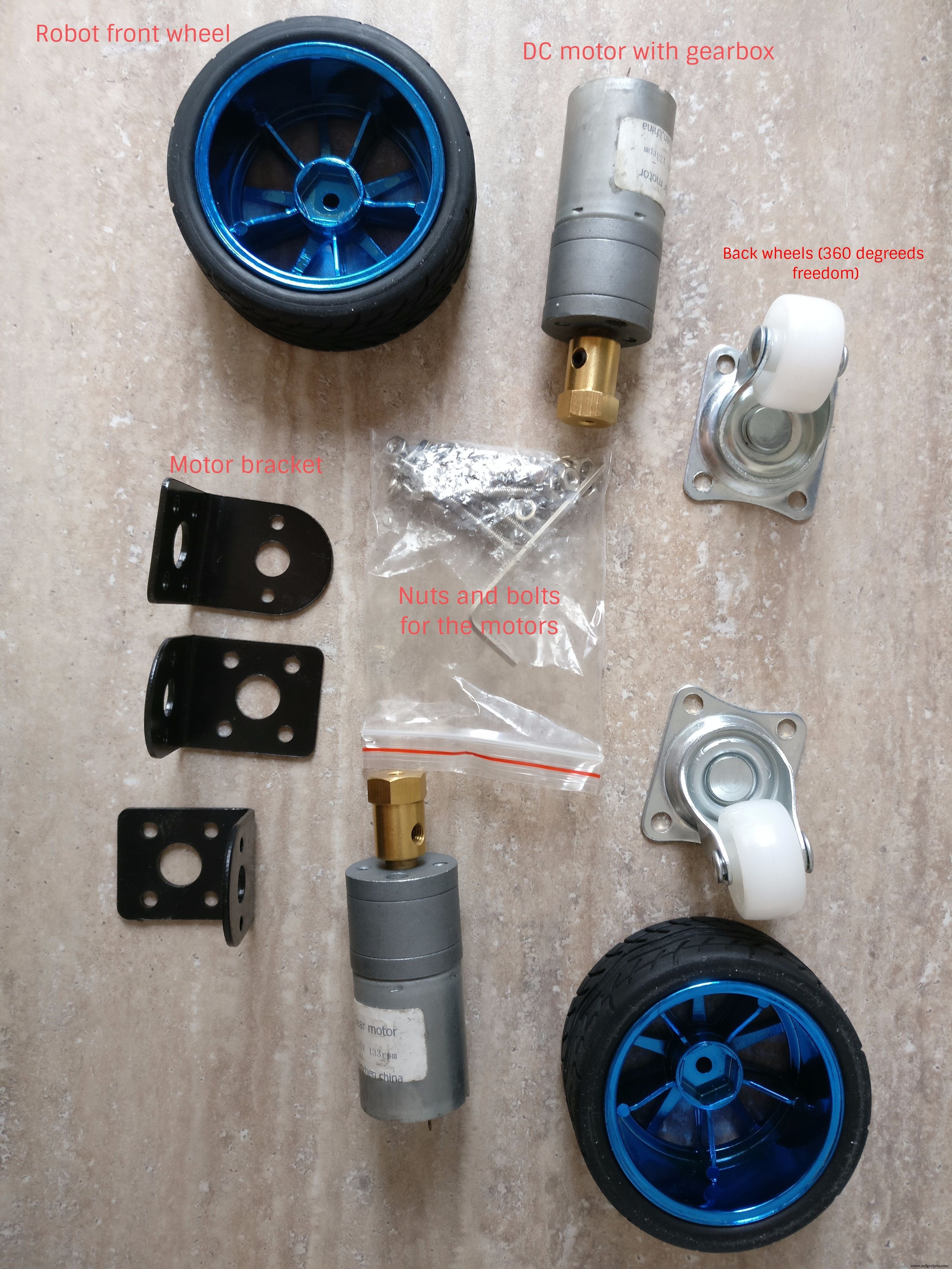
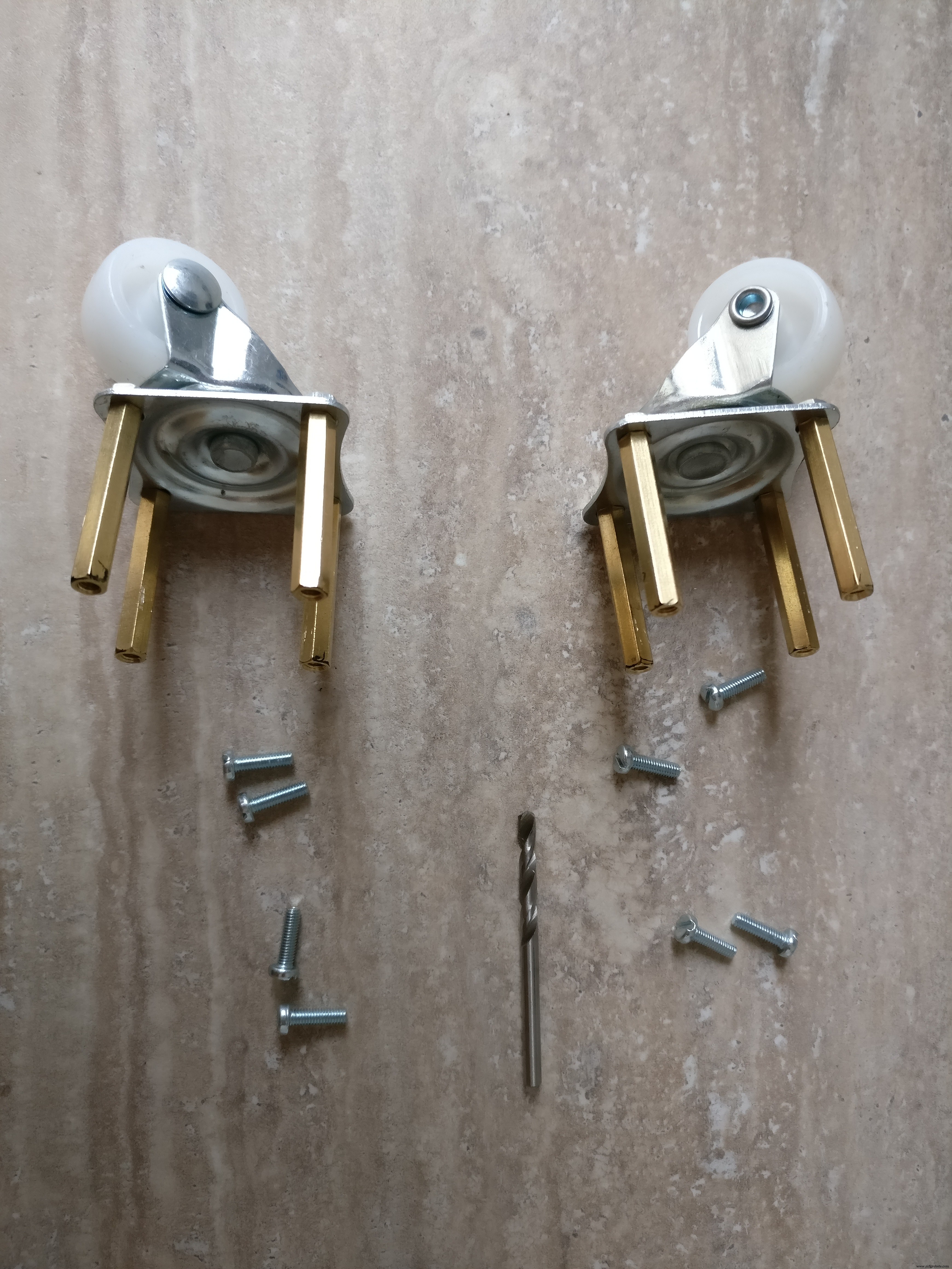
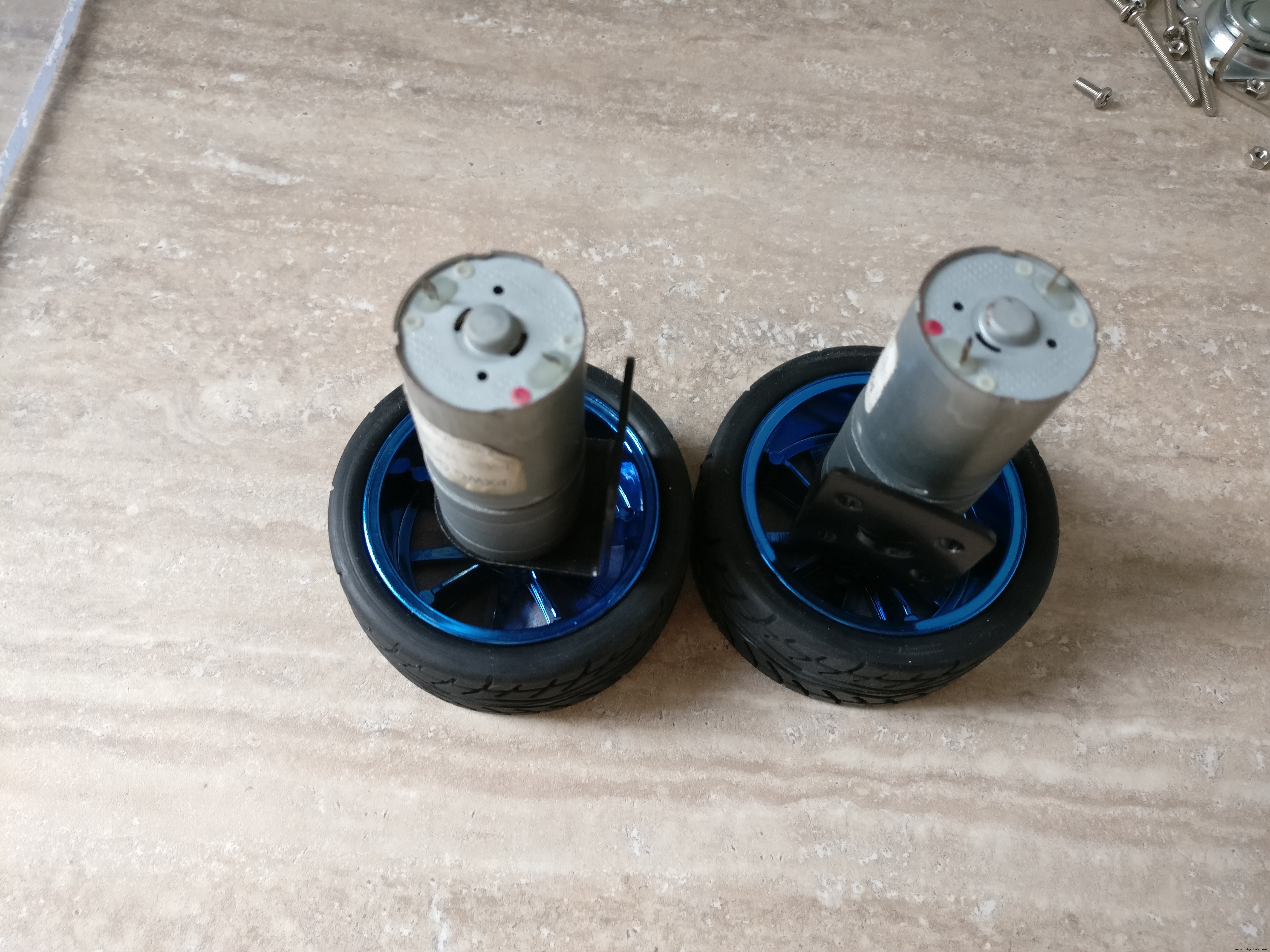
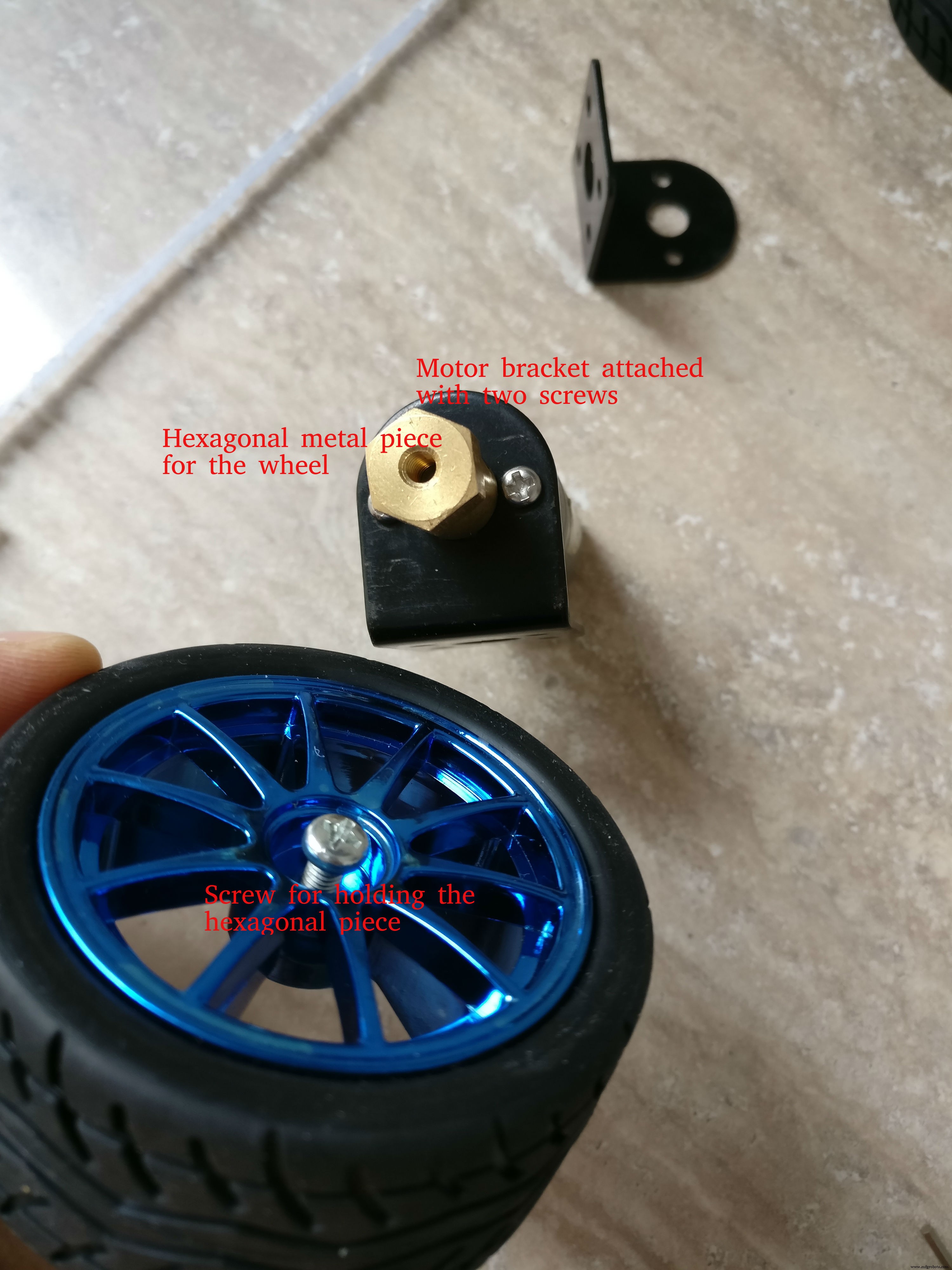
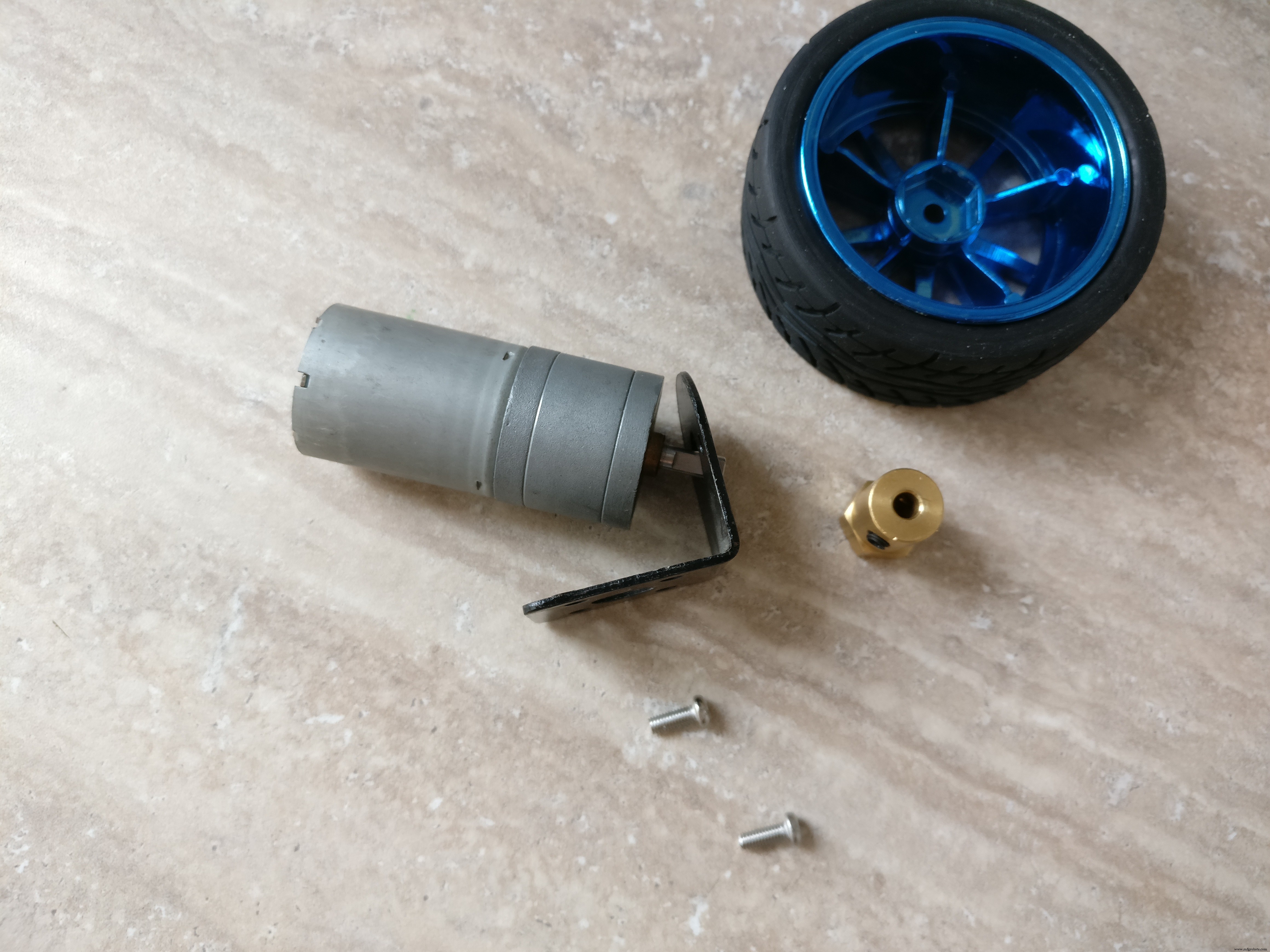
4.轮胎+直流电机带变速箱+支架。小螺母和螺栓,六角金属垫片
6. 2 x 任意方向轮轮胎
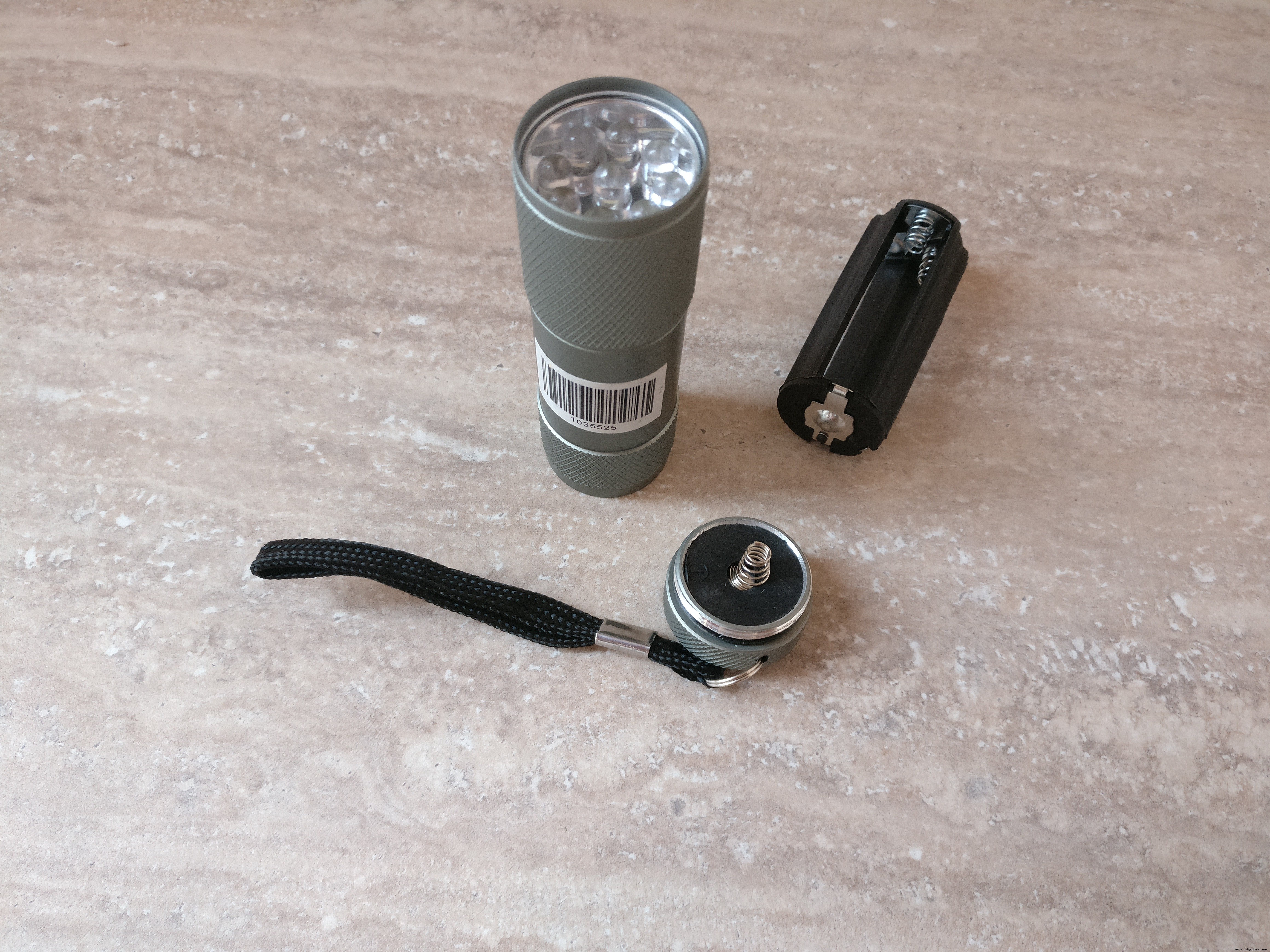
7. 小型LED手电筒(会变成头灯)
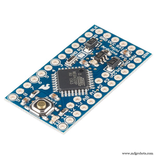
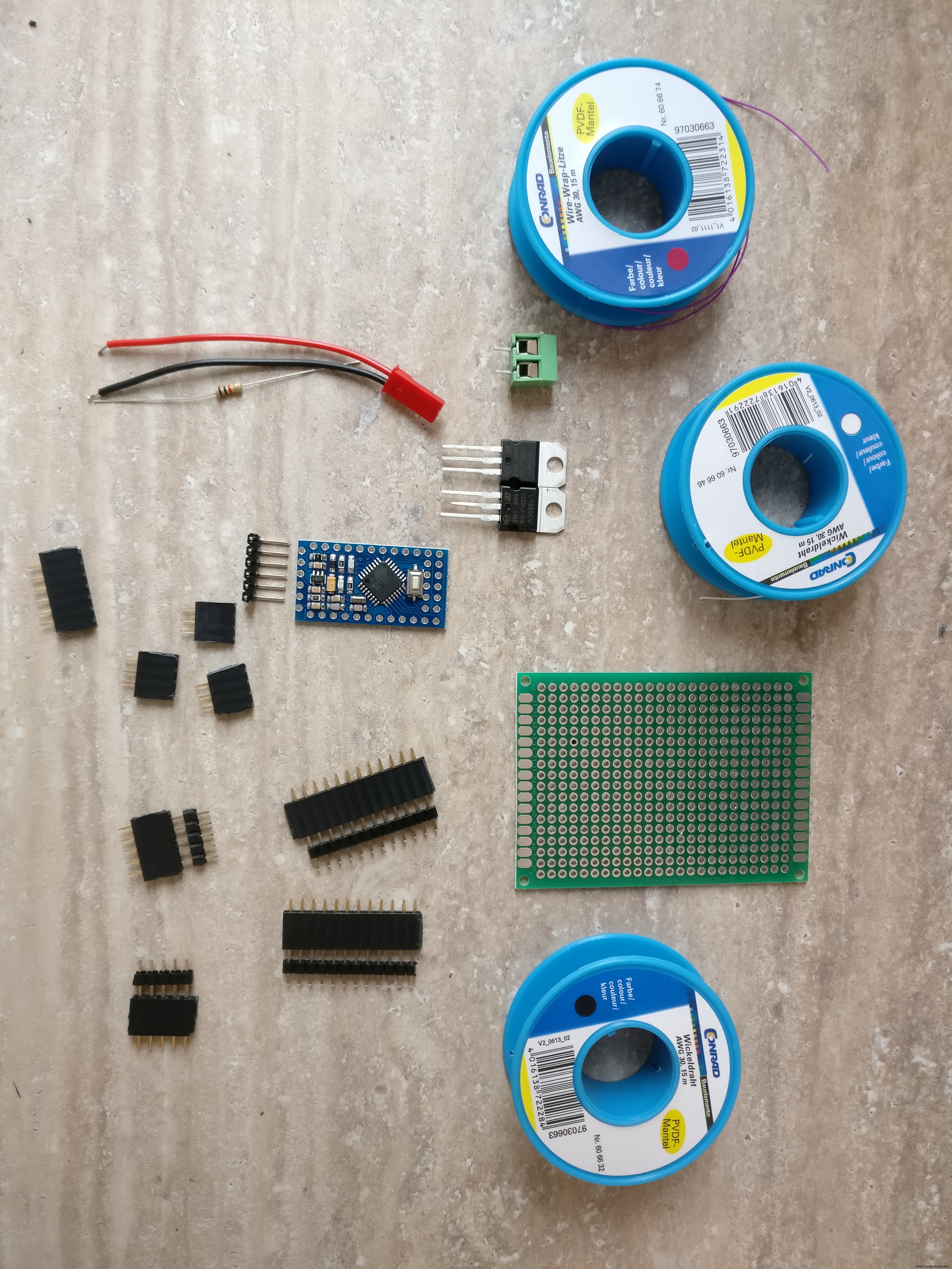
8. Arduino pro mini 328p
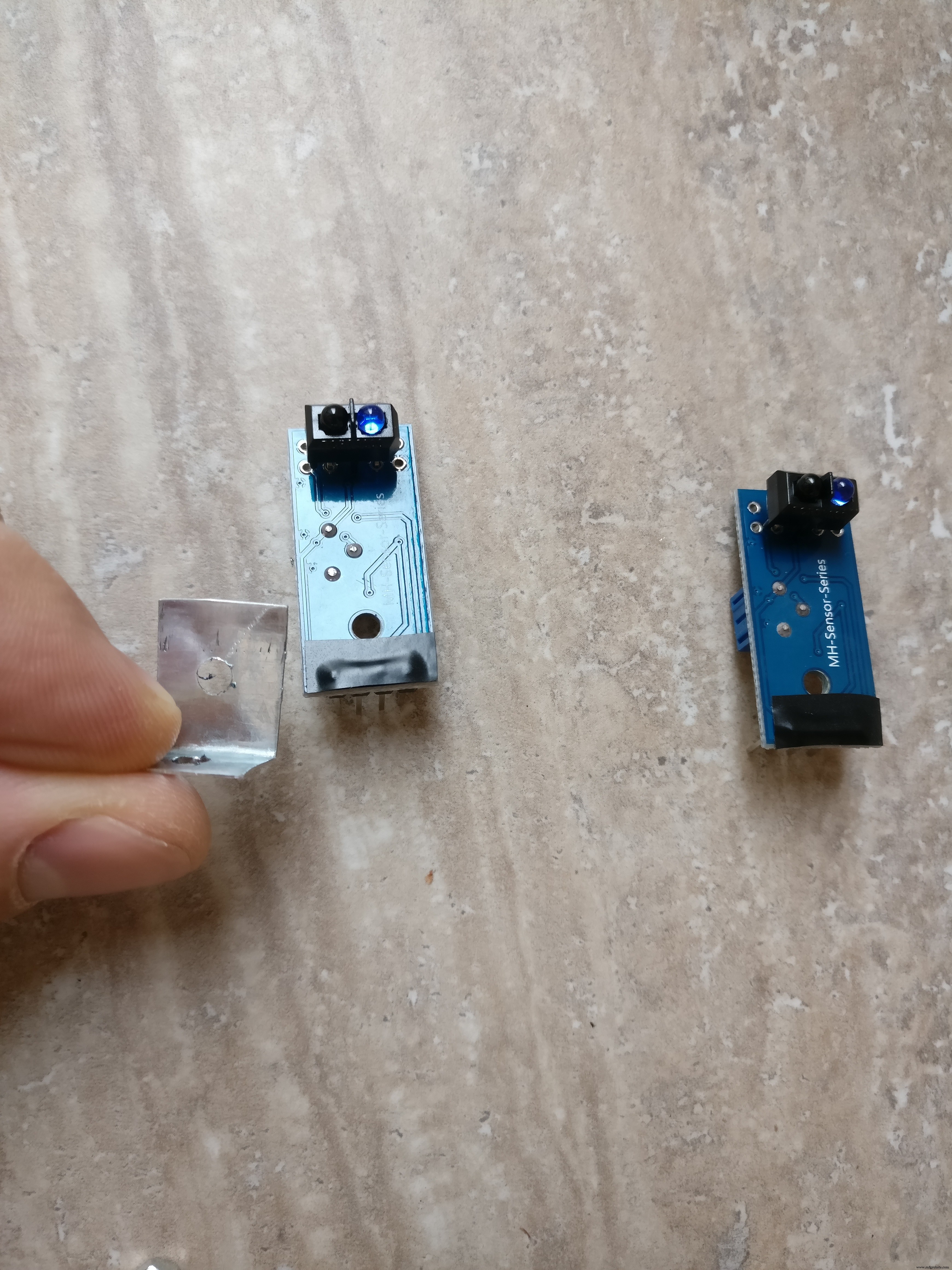
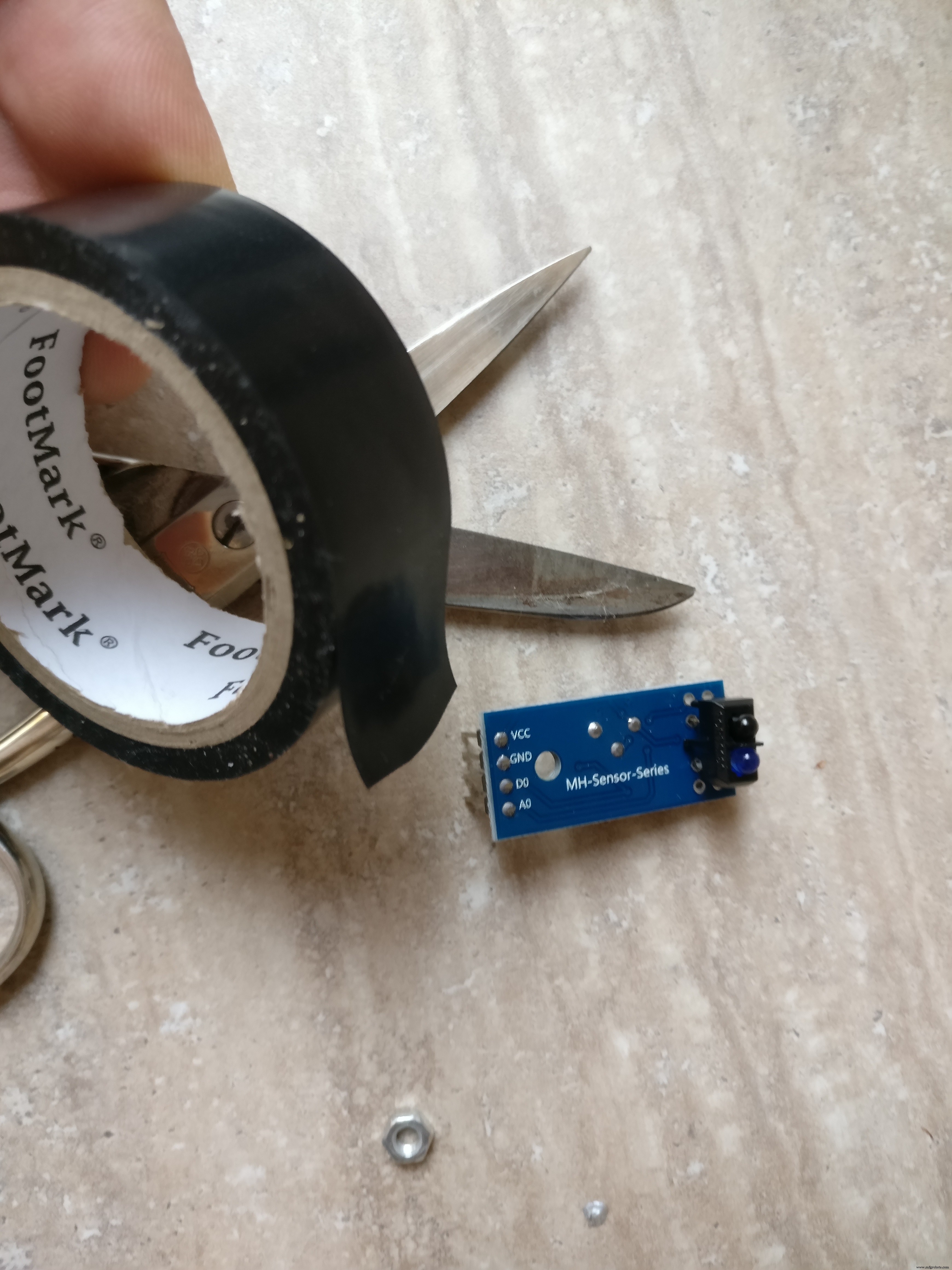
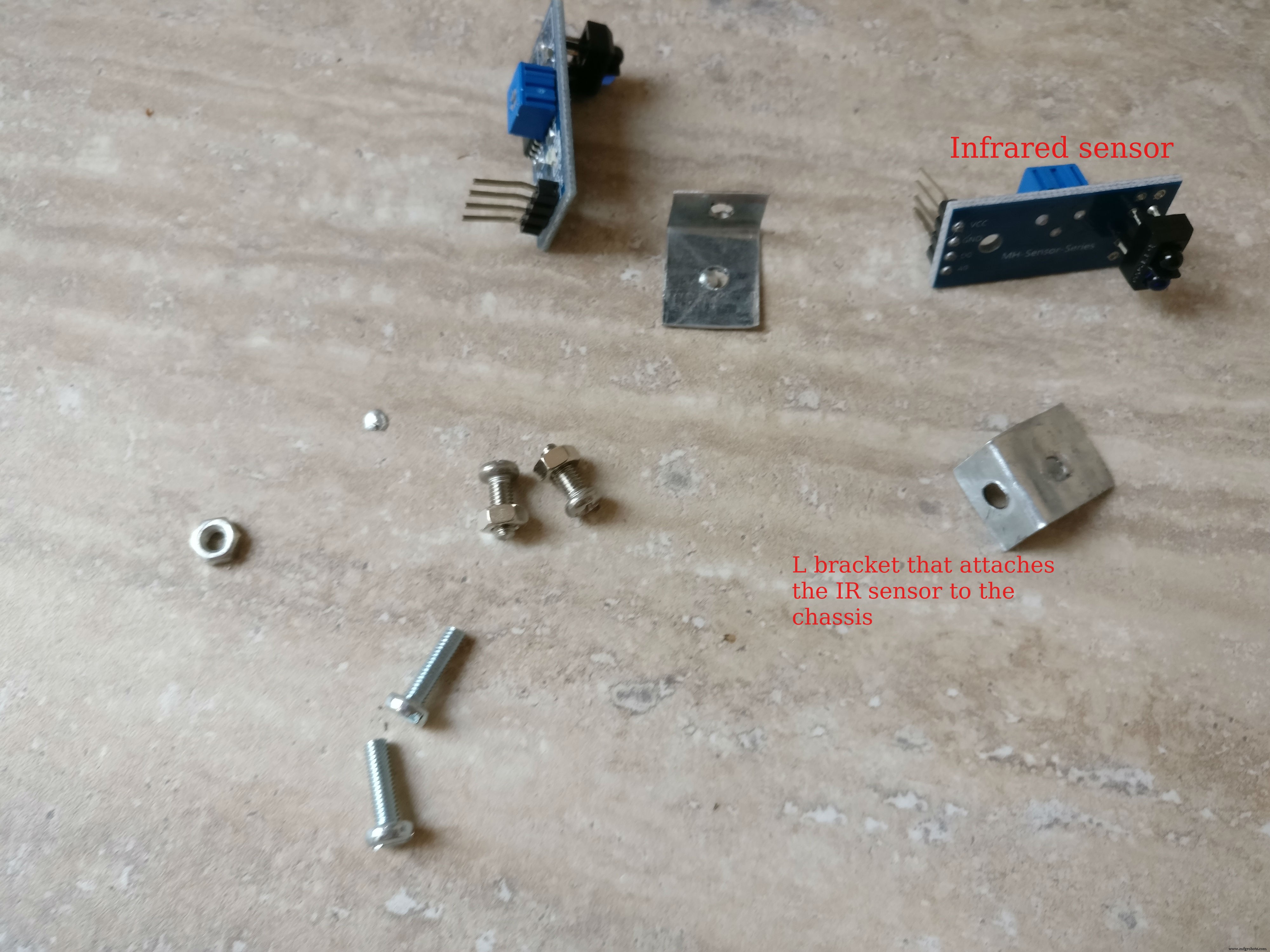
9. 2 x 红外障碍传感器
10. 印刷电路板
11. NPN tranzistor(驱动手电筒)
12. L7805CV 5V稳压器
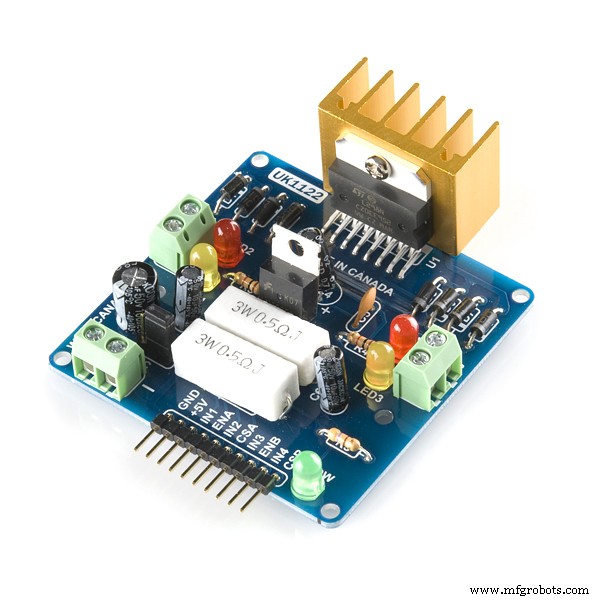
13. L298 H桥
14. Rezistor 220 欧姆
15.公USB连接器
16. 公微型 USB 连接器
17.各种电线
18. 3 v调节器(用于arduino和raspberry pi之间的通信)
19. 公母PCB连接器
20.开/关开关
21. XT-60 母头 LiPo 连接器
22. 2S 1300 mAh LiPo 电池,带 XT-60 连接器
23. 5v 电池组
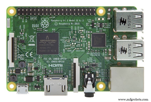
24. 树莓派 3
25.树莓派卡
26.树莓派案例
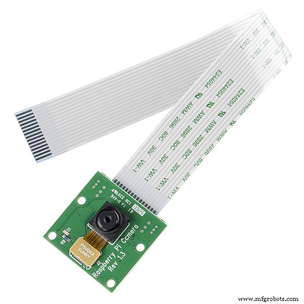
27.树莓派摄像头
工具: 1. USB转串口FTDI适配器FT232RL对arduino pro mini编程
2. Arduino IDE
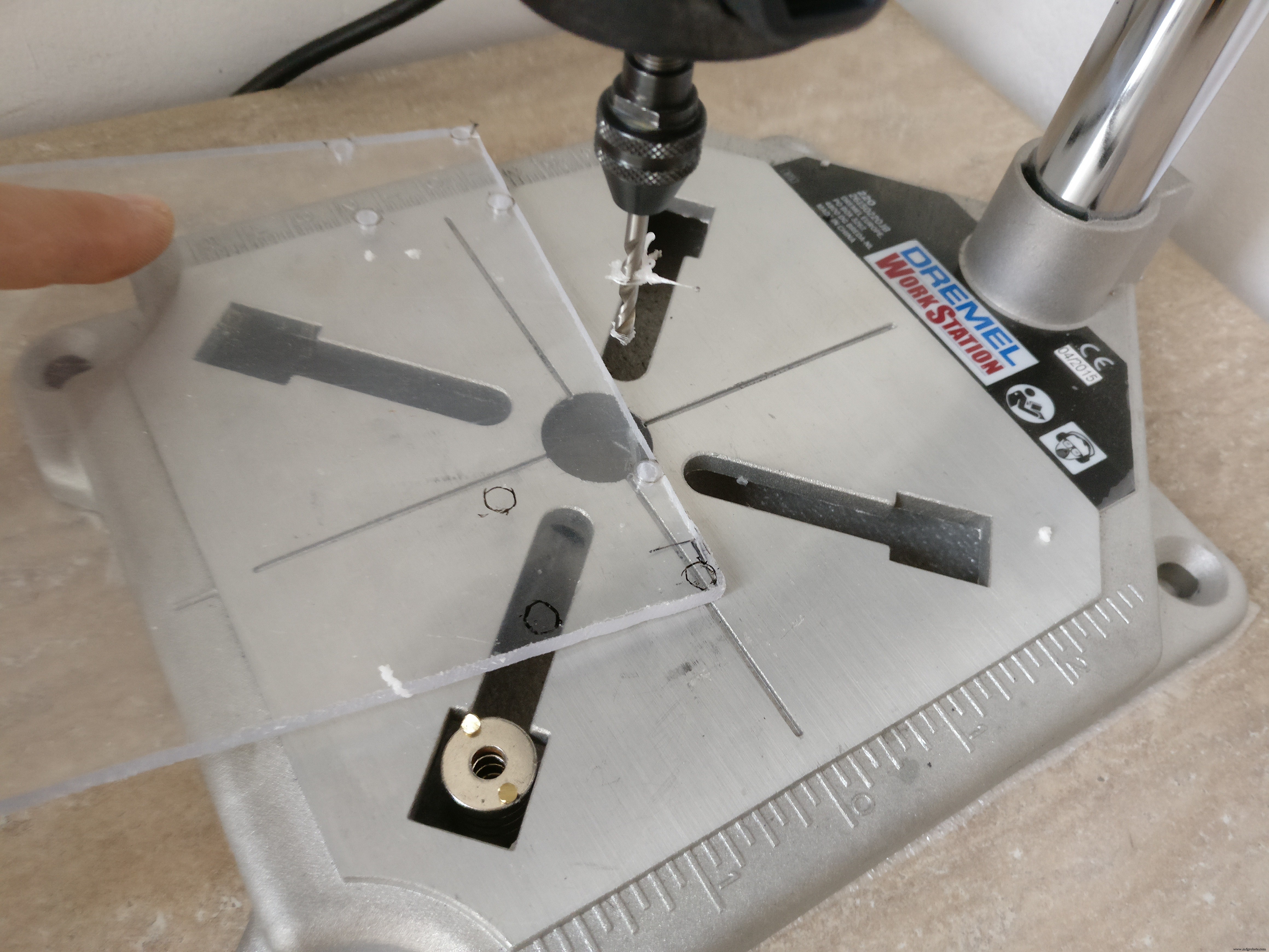
3. 钻孔
4. 细锯片
5. 螺丝刀
6. 烙铁
7. 剪线钳
技能:
1. 焊接,查看本教程
2.基本的arduino编程,这个教程可能有用
3.Linux服务配置、包安装
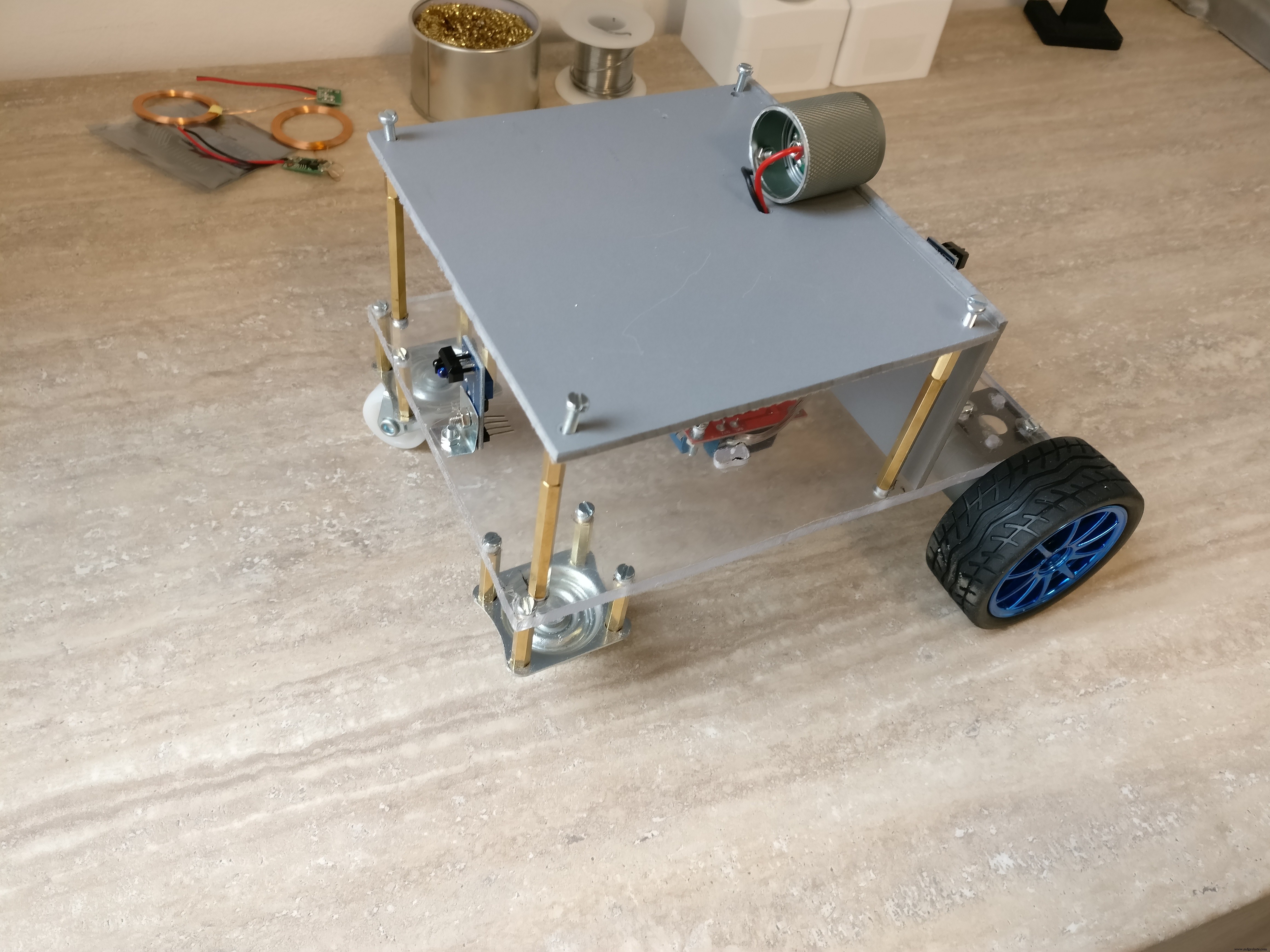
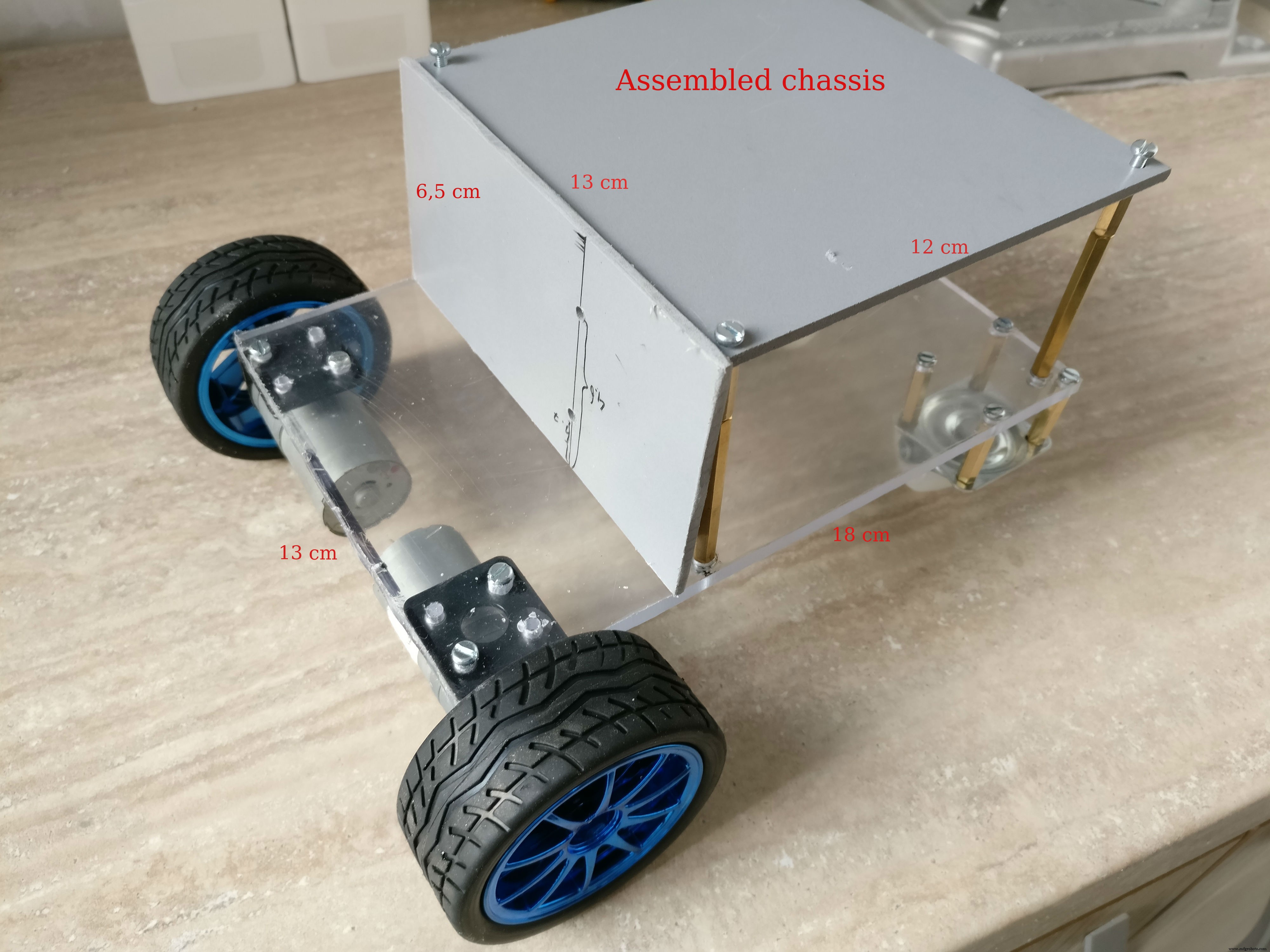
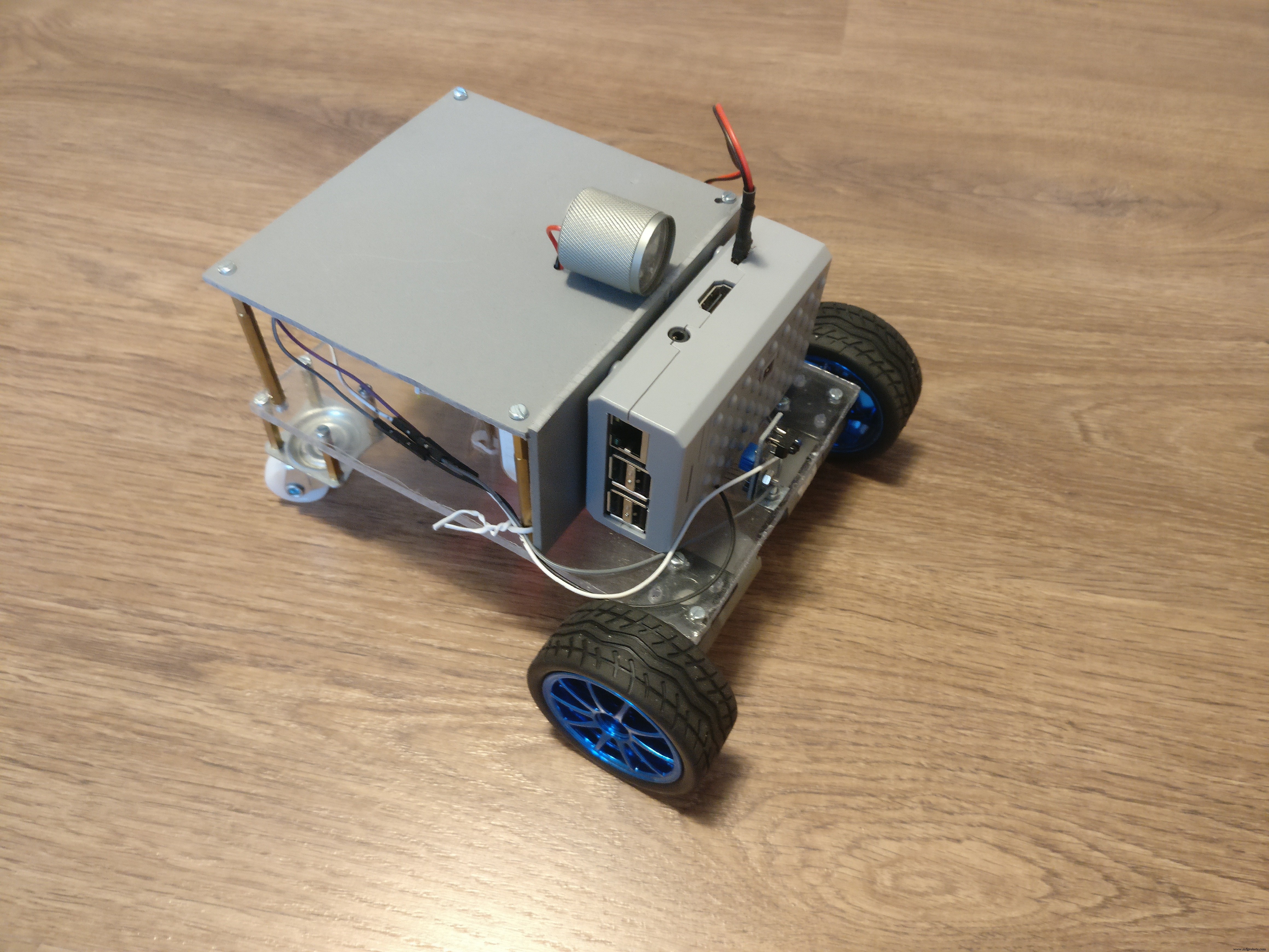
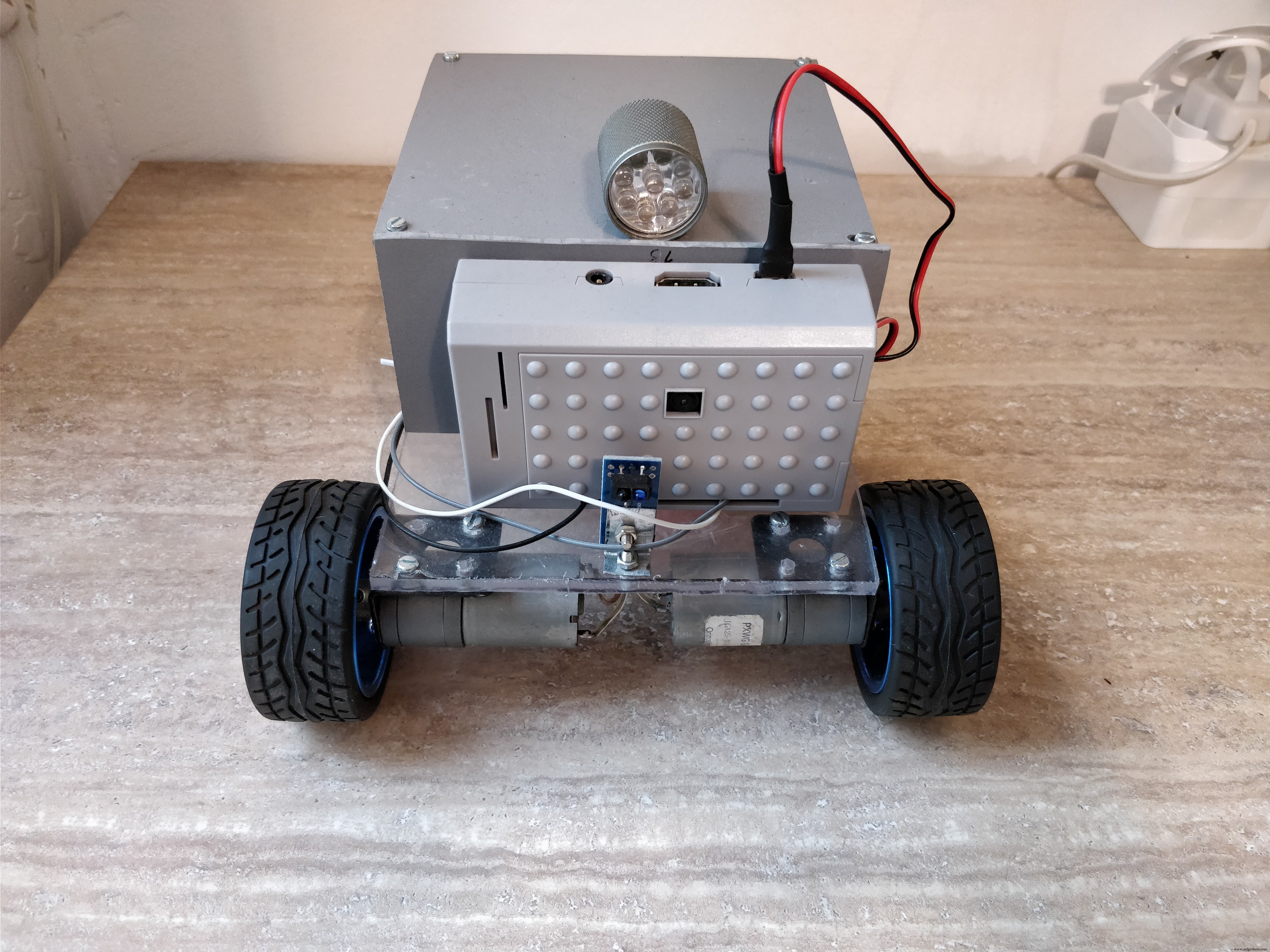
第二步:搭建机器人平台
机器人 我们将要建造的将具有以下规格 :
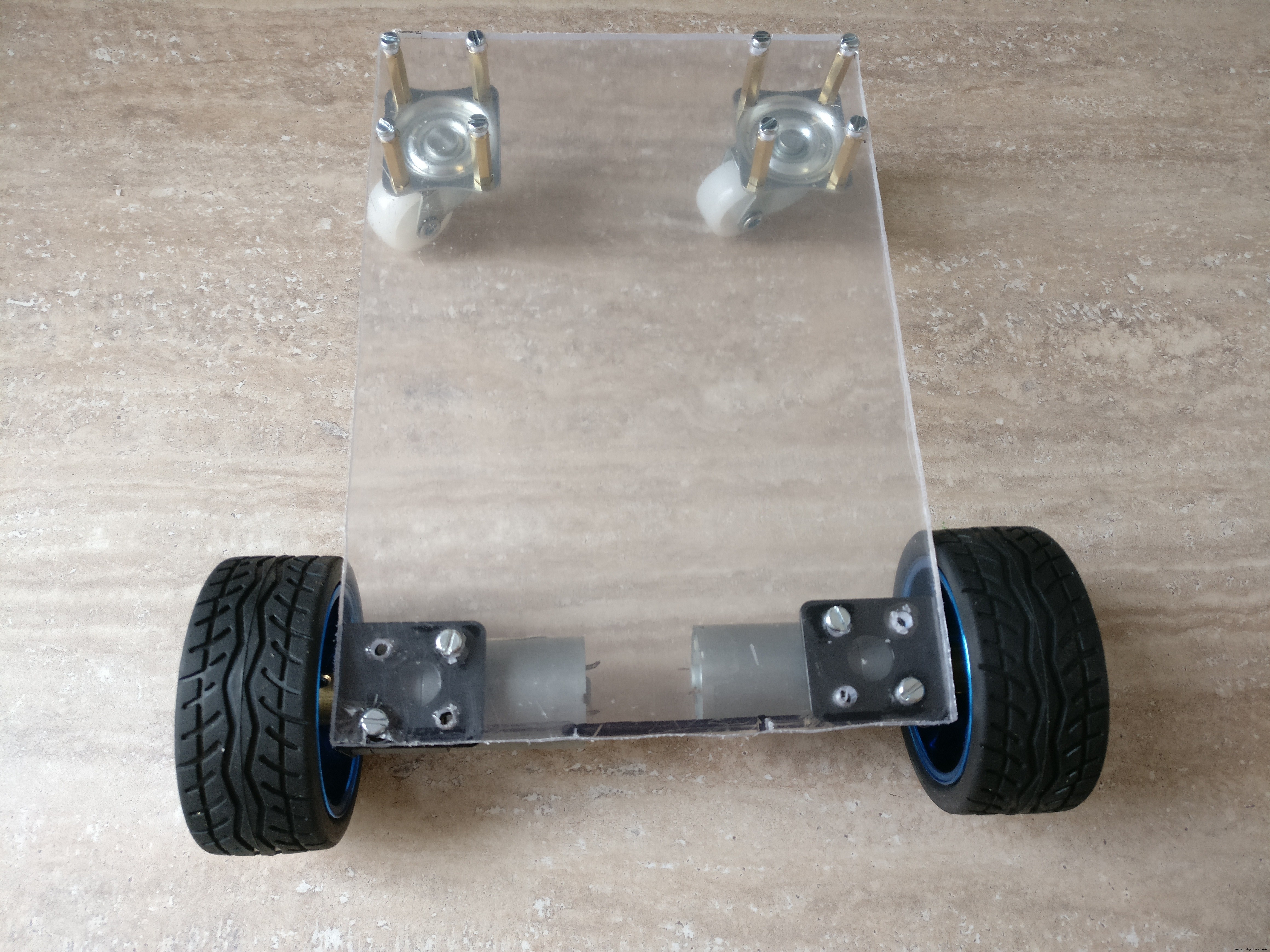
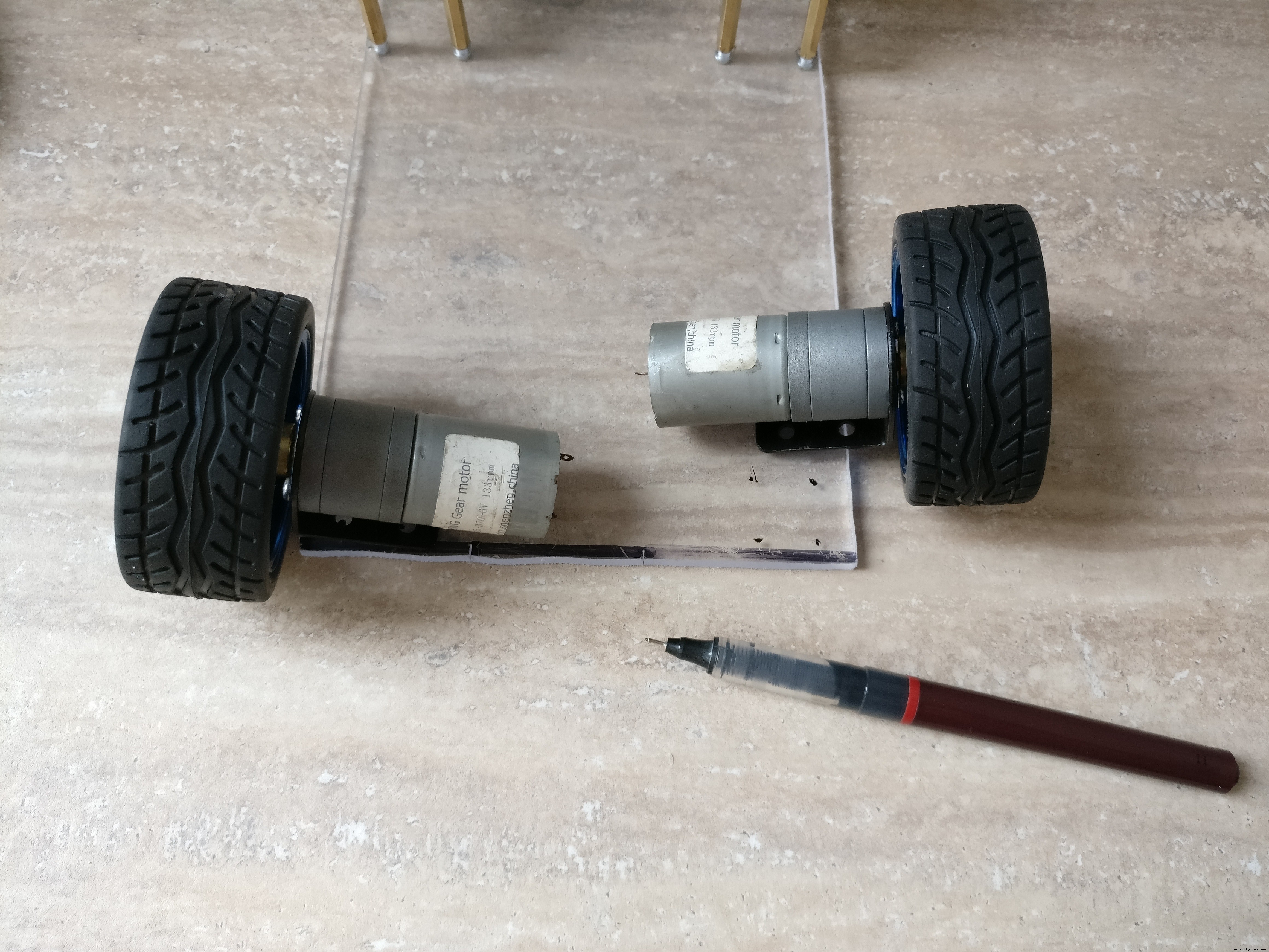
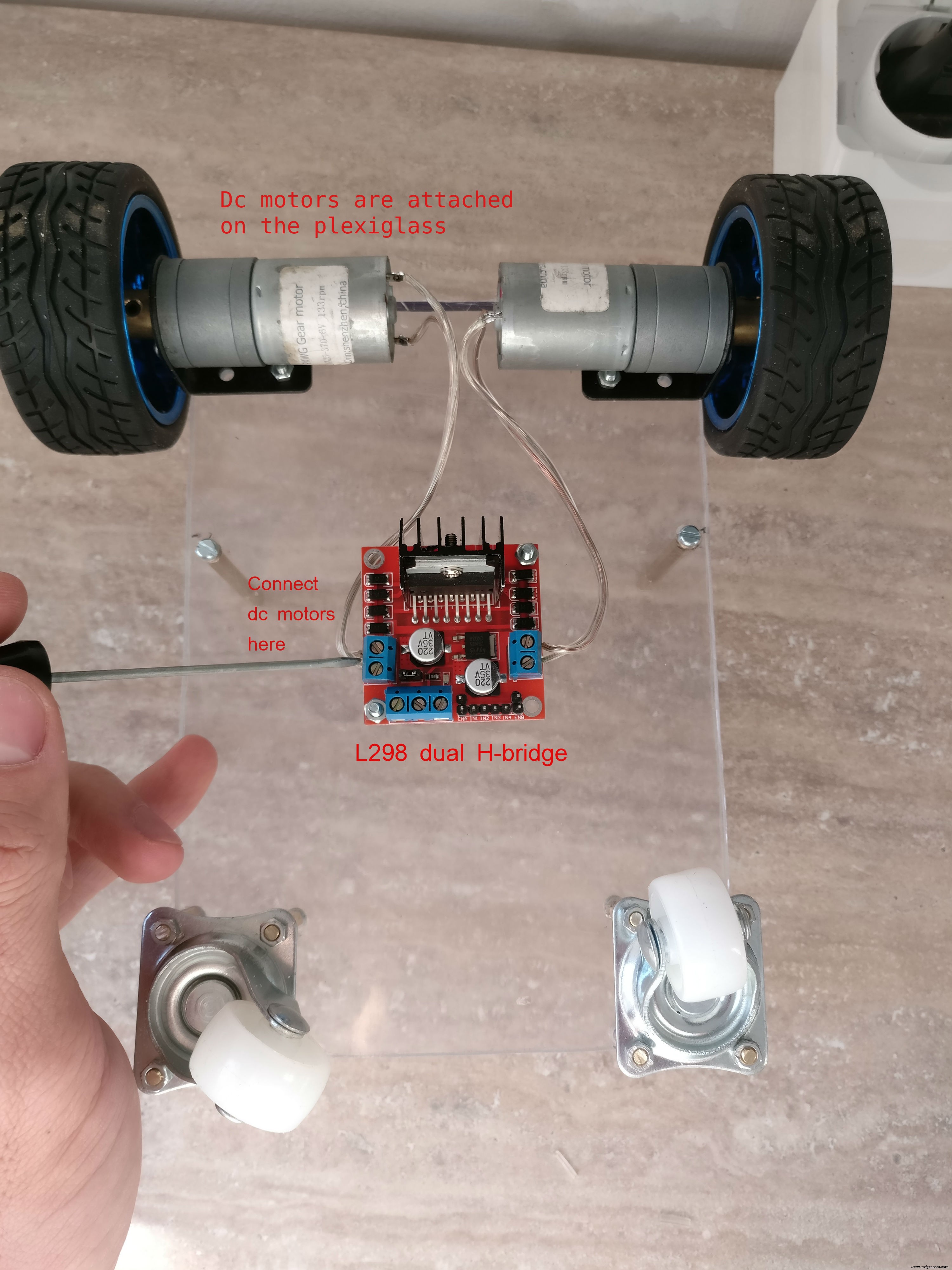
- 两个独立的直流电机对前轮进行牵引
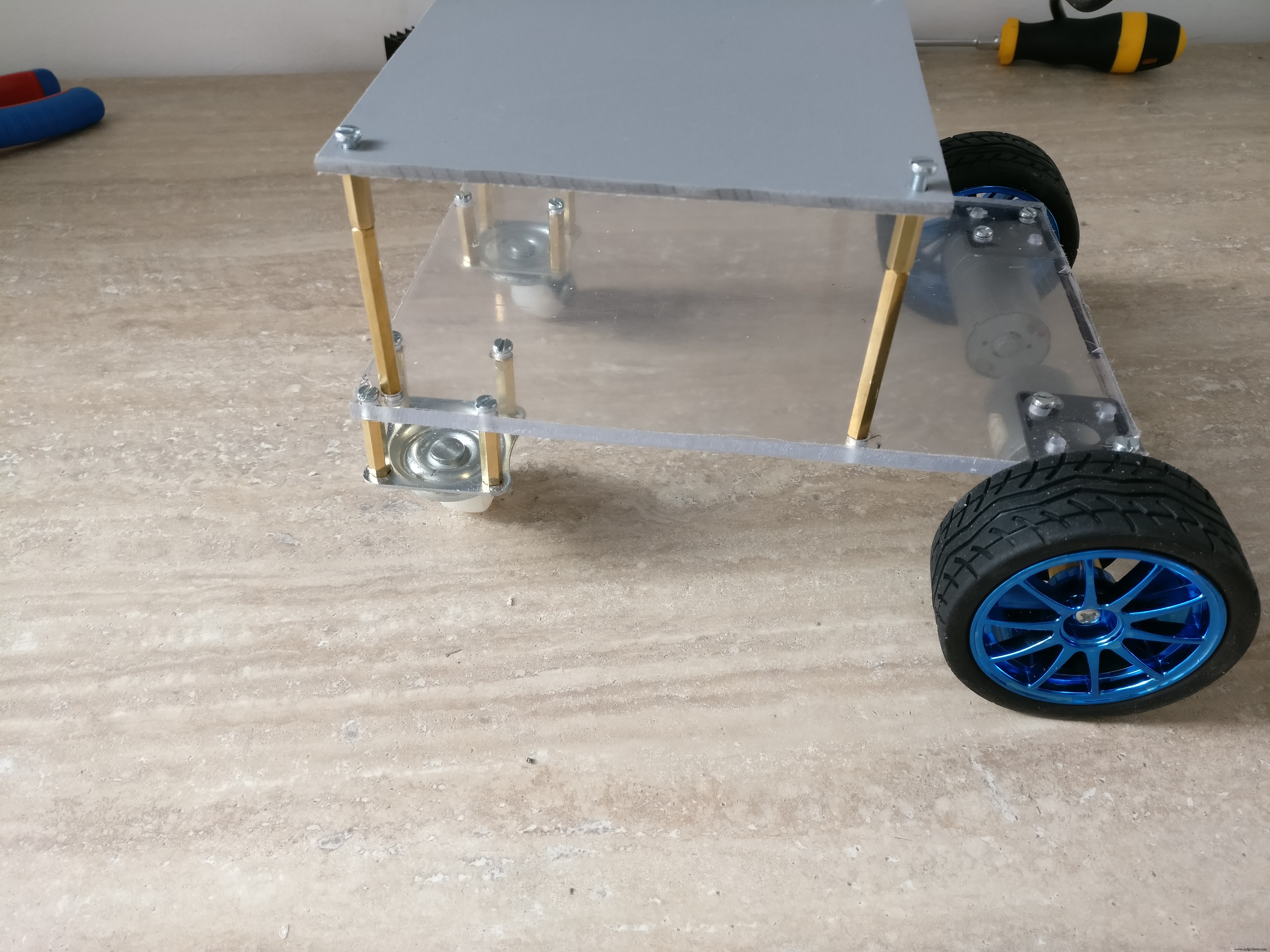
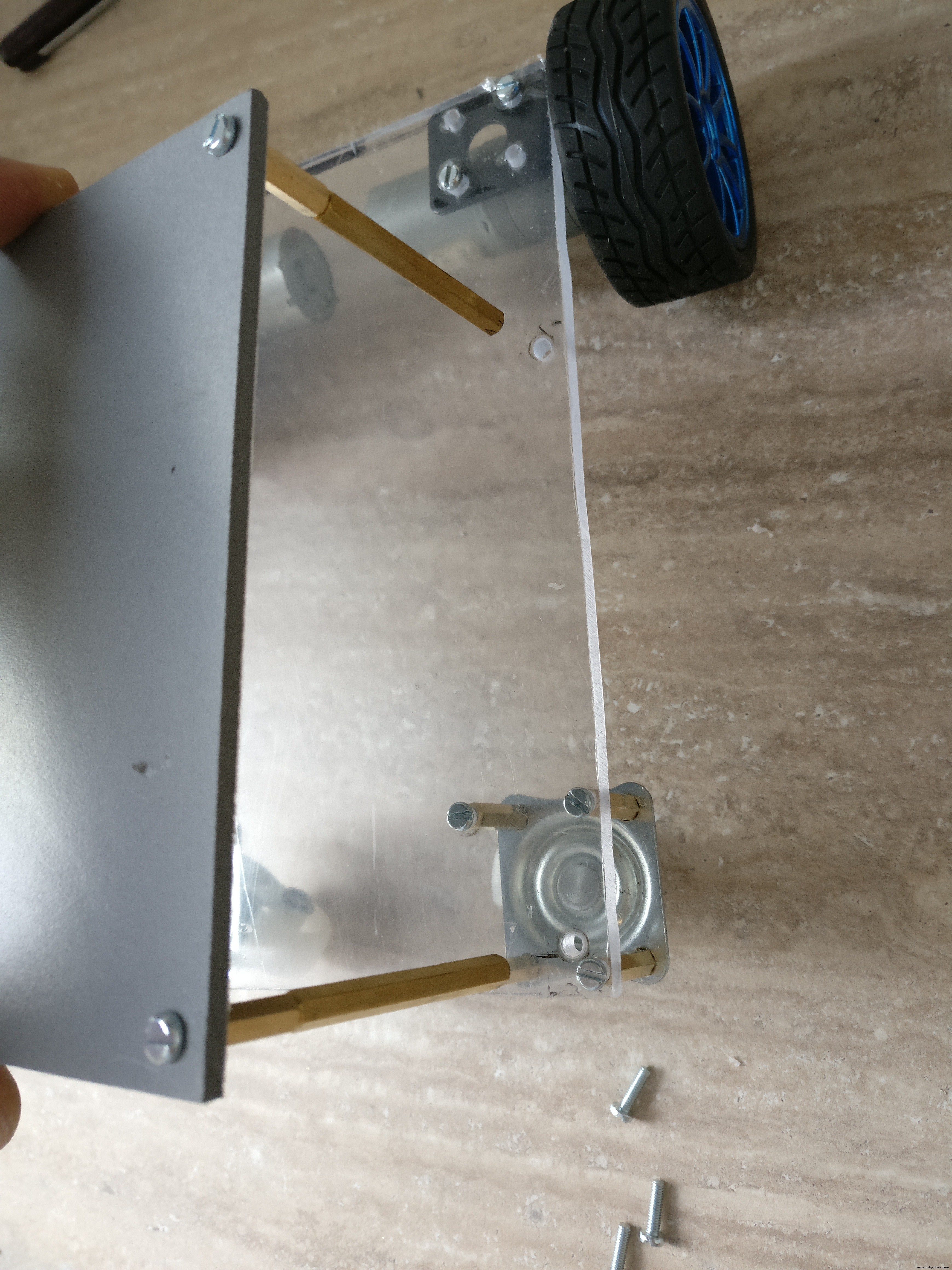
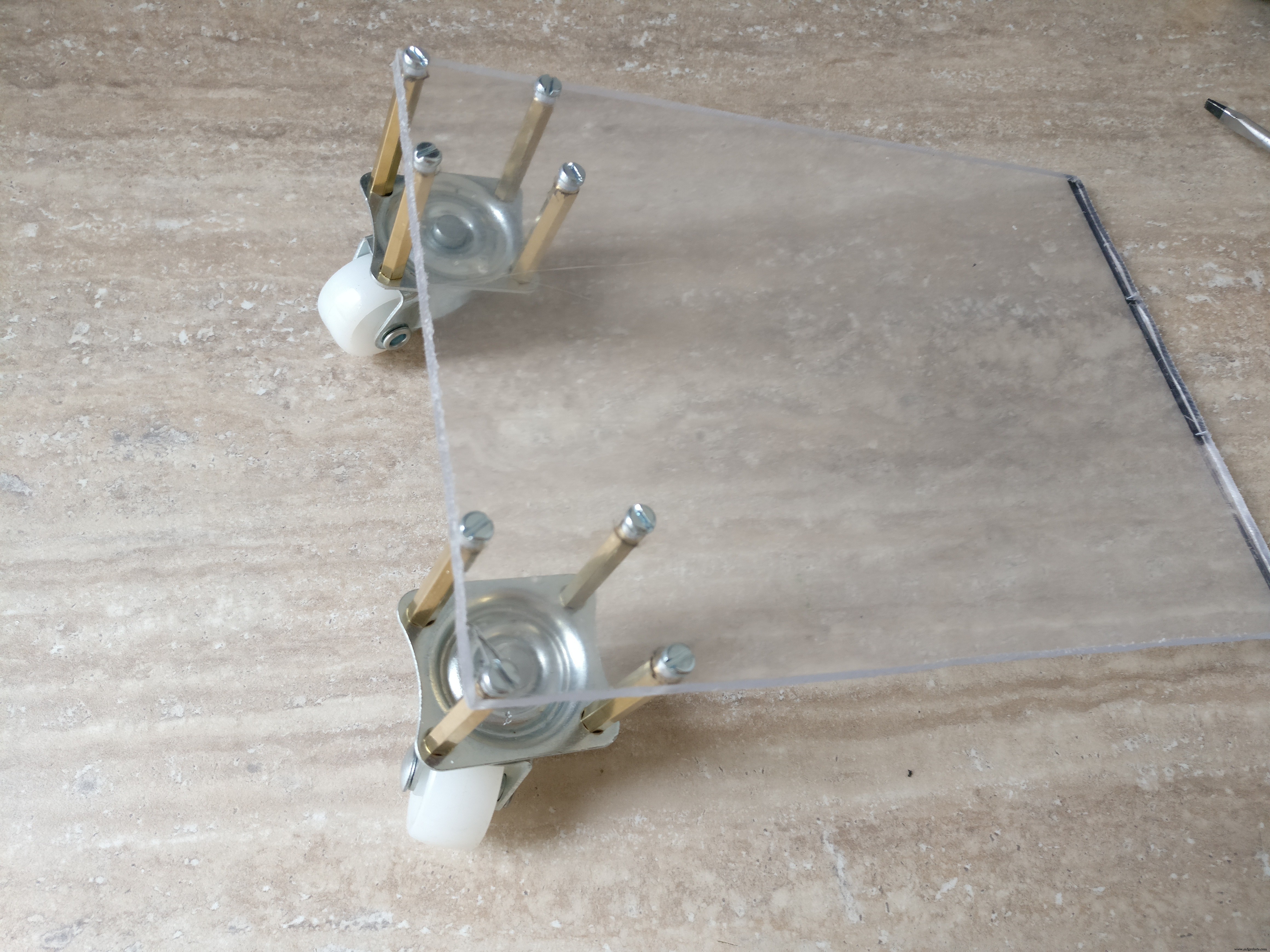
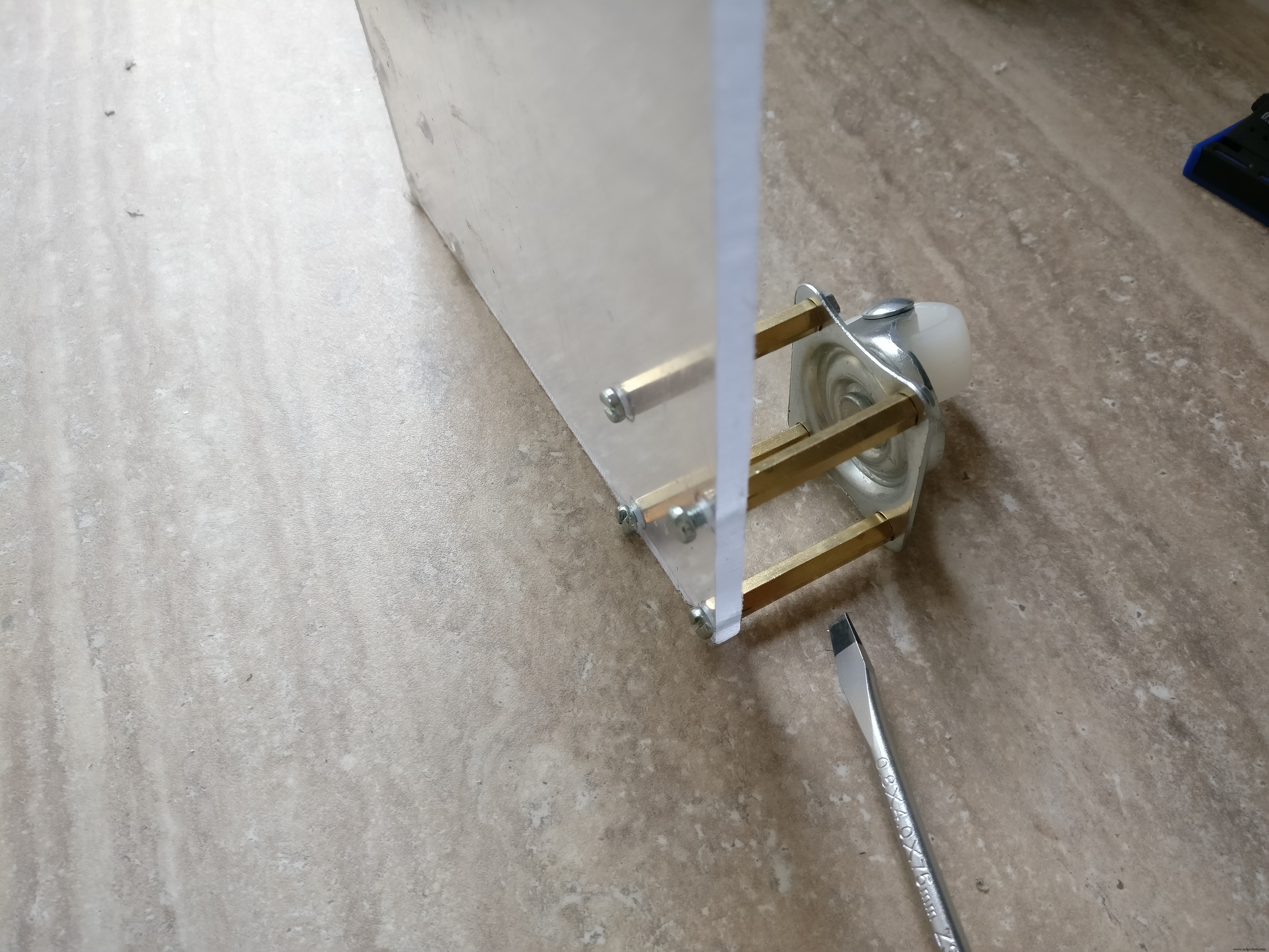
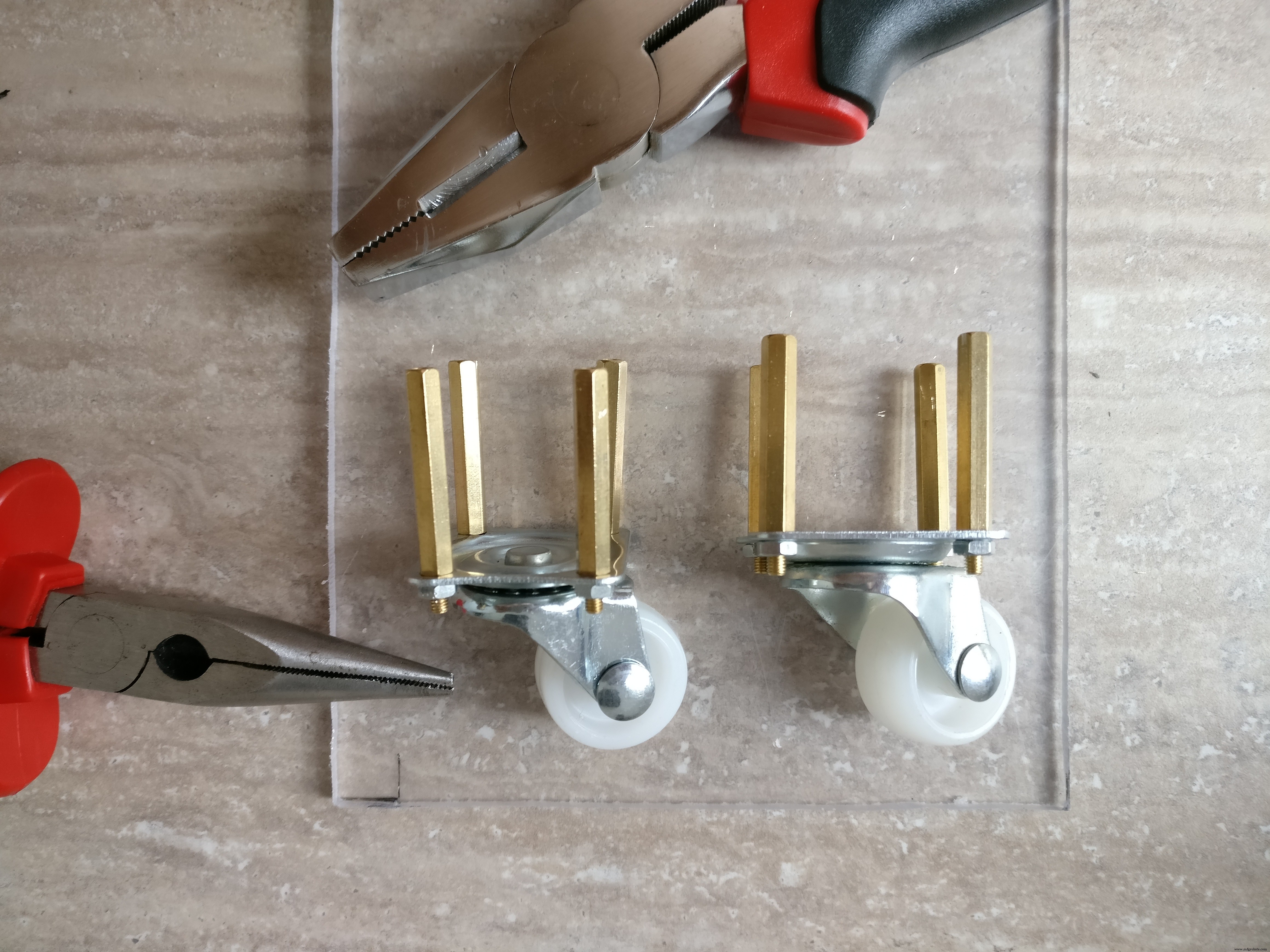
- 后轮应该能够在任何方向360度移动
- 方向由前轮变速控制,不需要单独的方向机构,机器人也可以原地旋转
- 顶部会有灯
- 它应该有足够的空间放置电子设备、电池和带摄像头的树莓派外壳
- 需要几厘米的离地间隙才能克服小障碍
不要忘记查看图像以了解重要的细节和构建技巧。

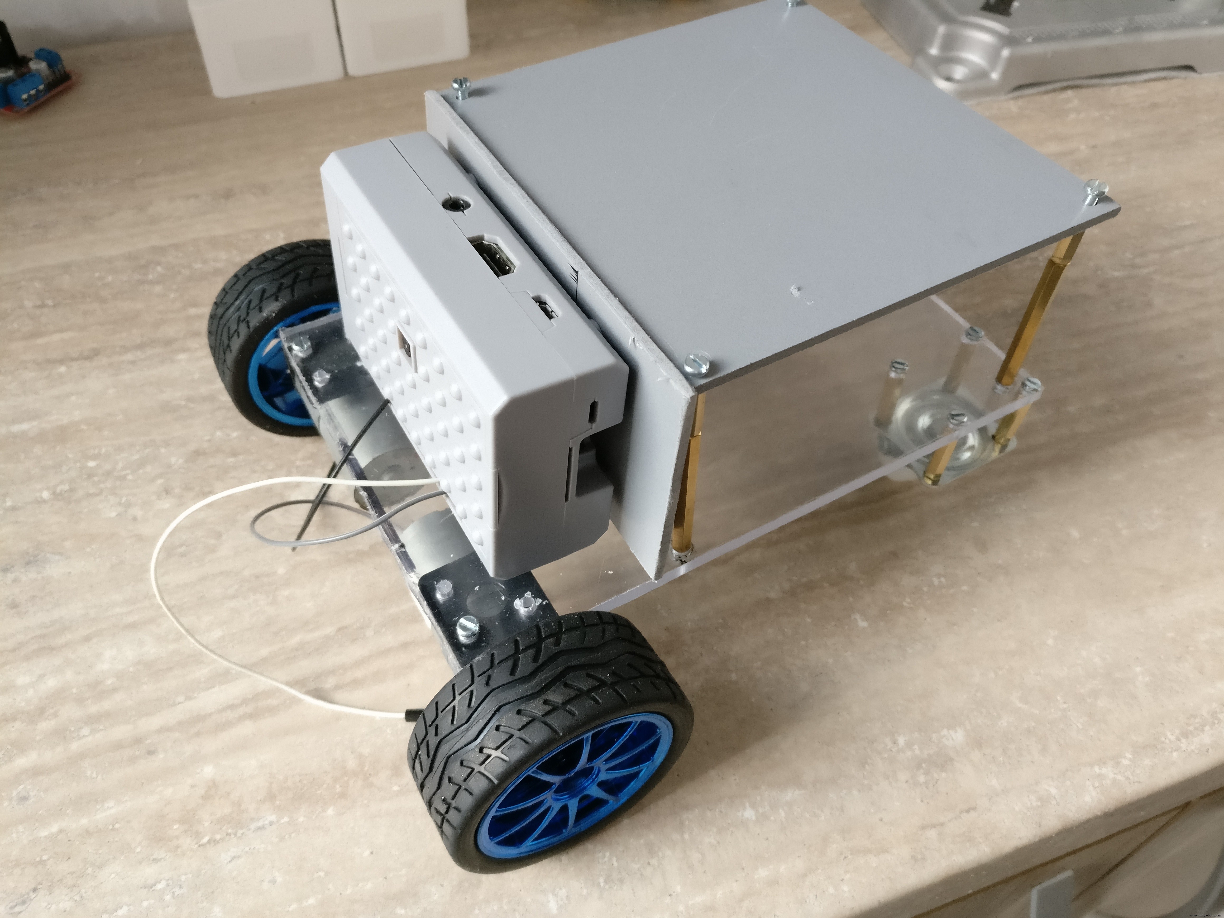


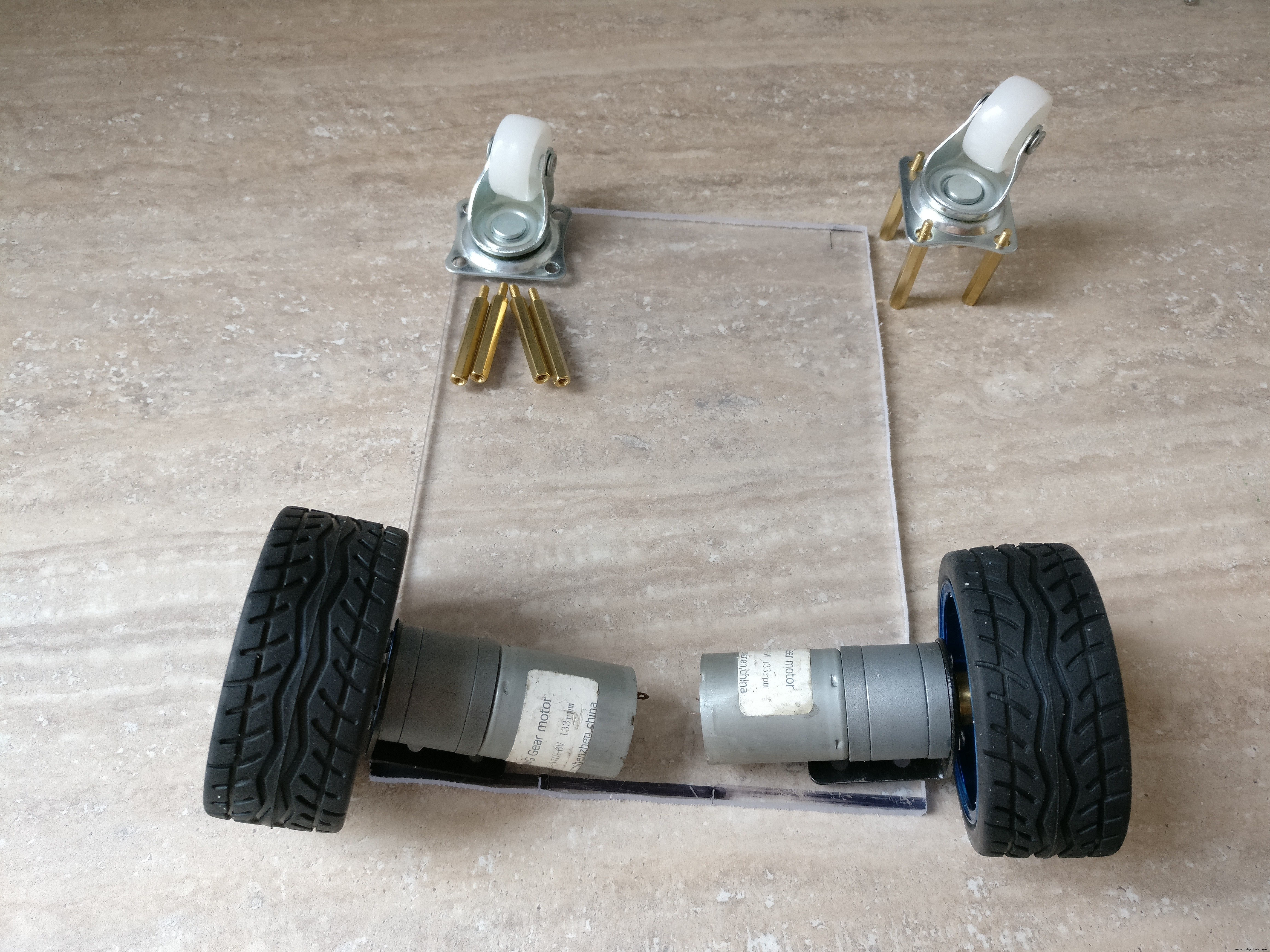
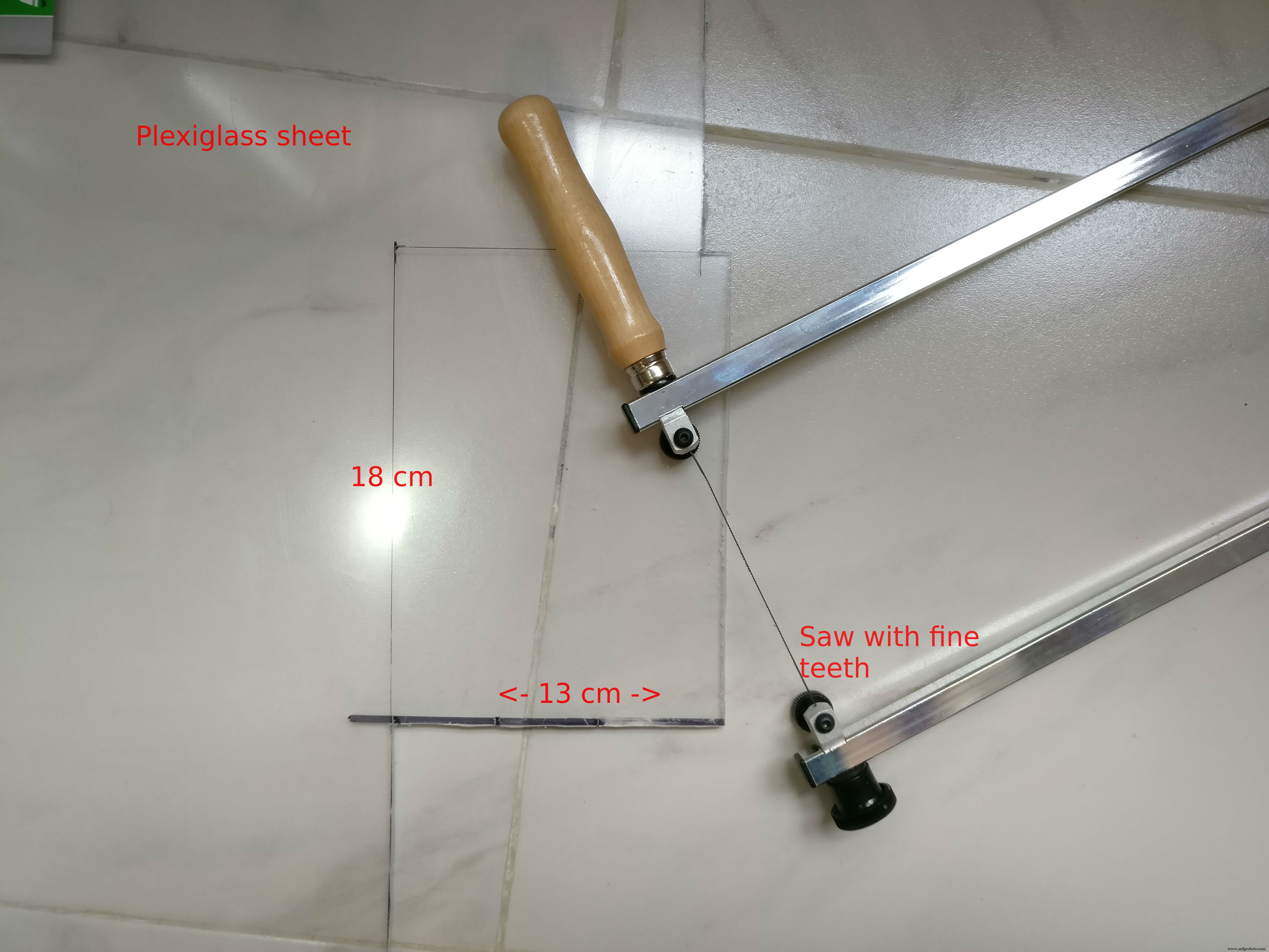

我们将用有机玻璃或硬塑料制造机器人,我都用过它们,但你可以选择任何你想要的。
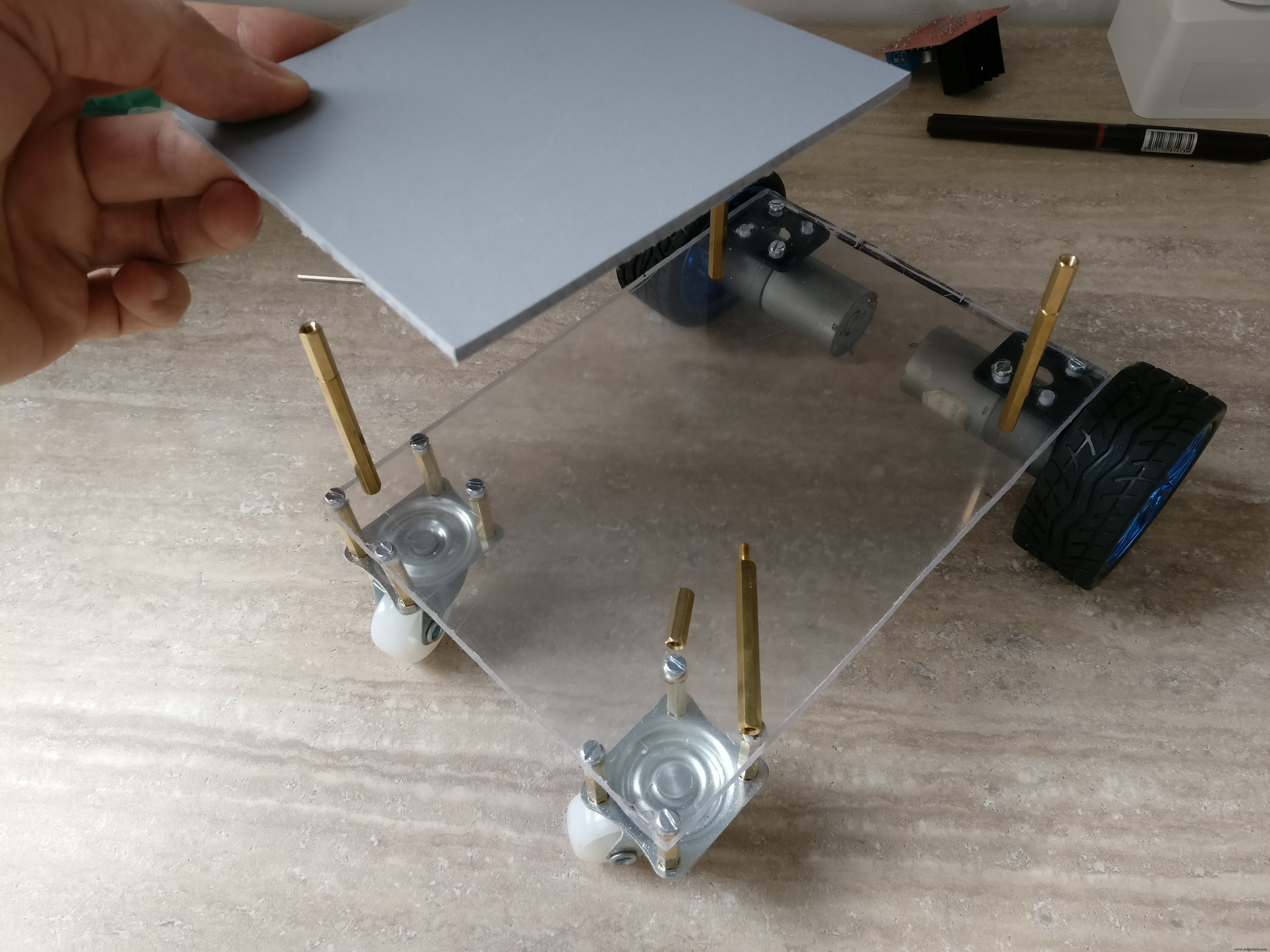
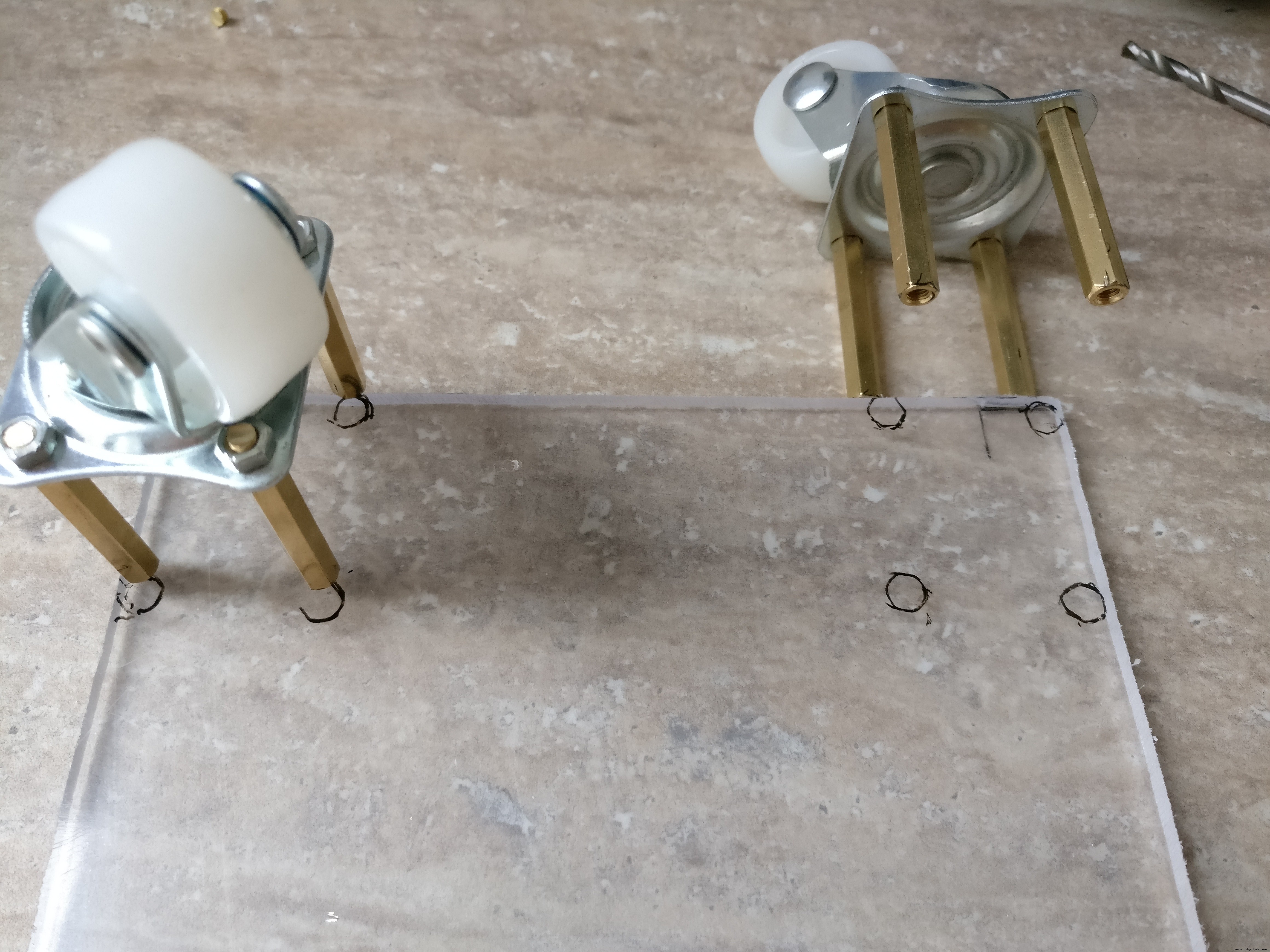
底板 将在底板上为 18 x 13 厘米,直流发动机将用金属支架螺母和螺栓连接。 H 桥将安装在面向地板的板中间。后轮将使用 2 厘米六角金属垫片(一侧公一侧母)连接
需要在 H 桥附近开一个大孔来连接顶部的电子设备。
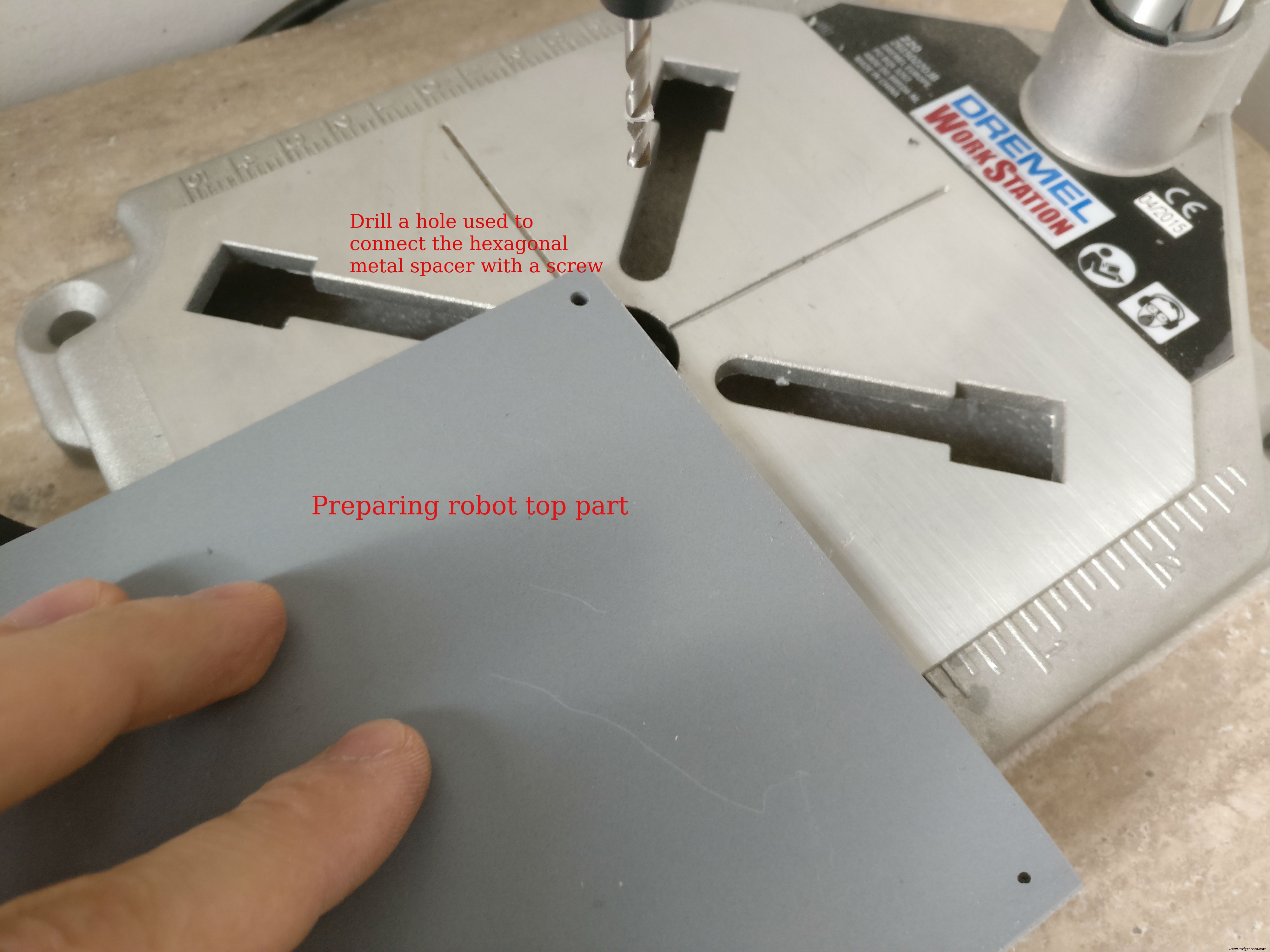
顶部 机器人由两个“L”形板组成,一个是 12 x 13 厘米,另一个是 6,5 x 13 厘米。塑料板将粘在一起。这些板将为电子设备提供盖板、安装前灯的位置和树莓派外壳的支撑。顶部将使用 6 厘米六角金属垫片从底部连接 )
第 3 步:构建电子设备


引脚分配(arduino):
手电筒:D3
左电机:PWM (D5), EN1, EN2(A4, A5)
右马达:PWM (D6), EN1, EN2(A3, A2)
红外传感器:正面(A0),背面(A1)
树莓派通讯引脚:Tx:D11,Rx:D10
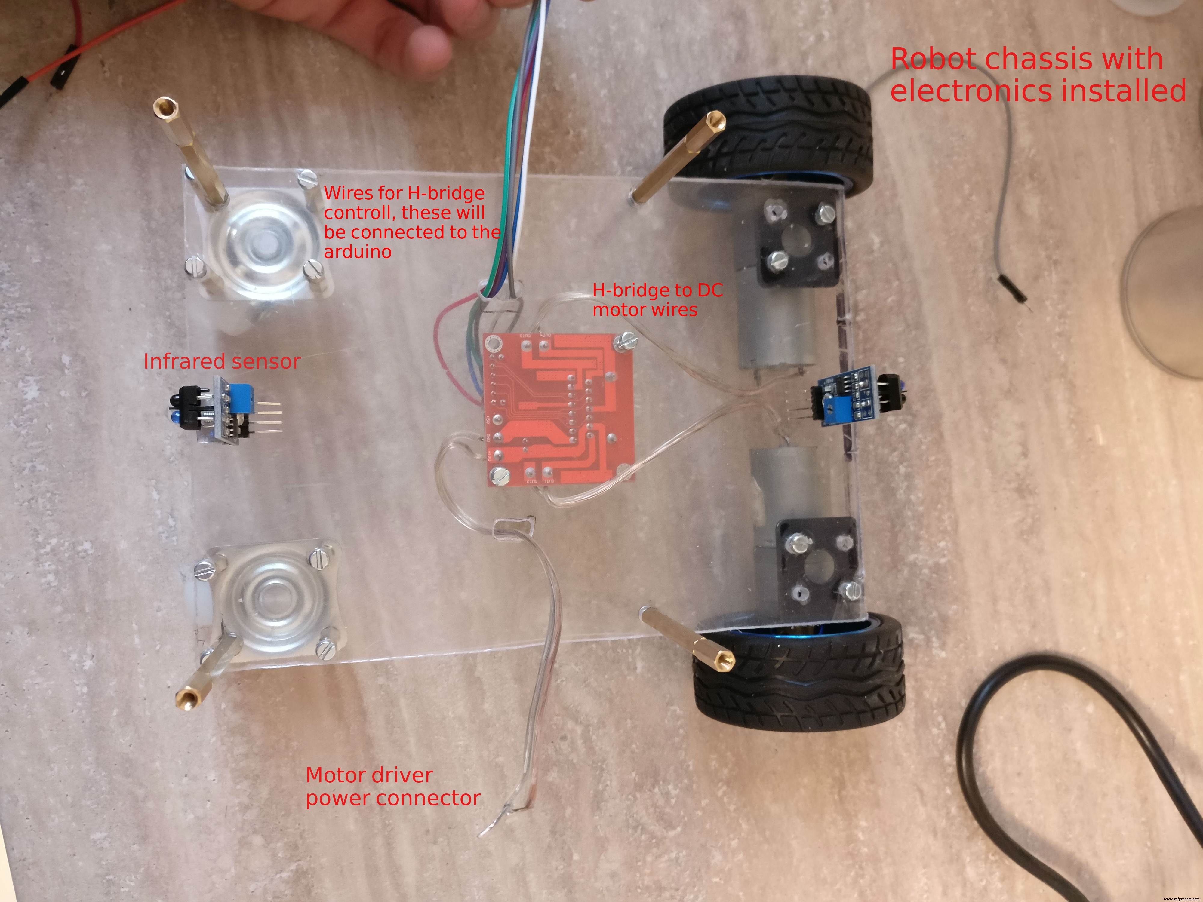
构建 PCB,组装
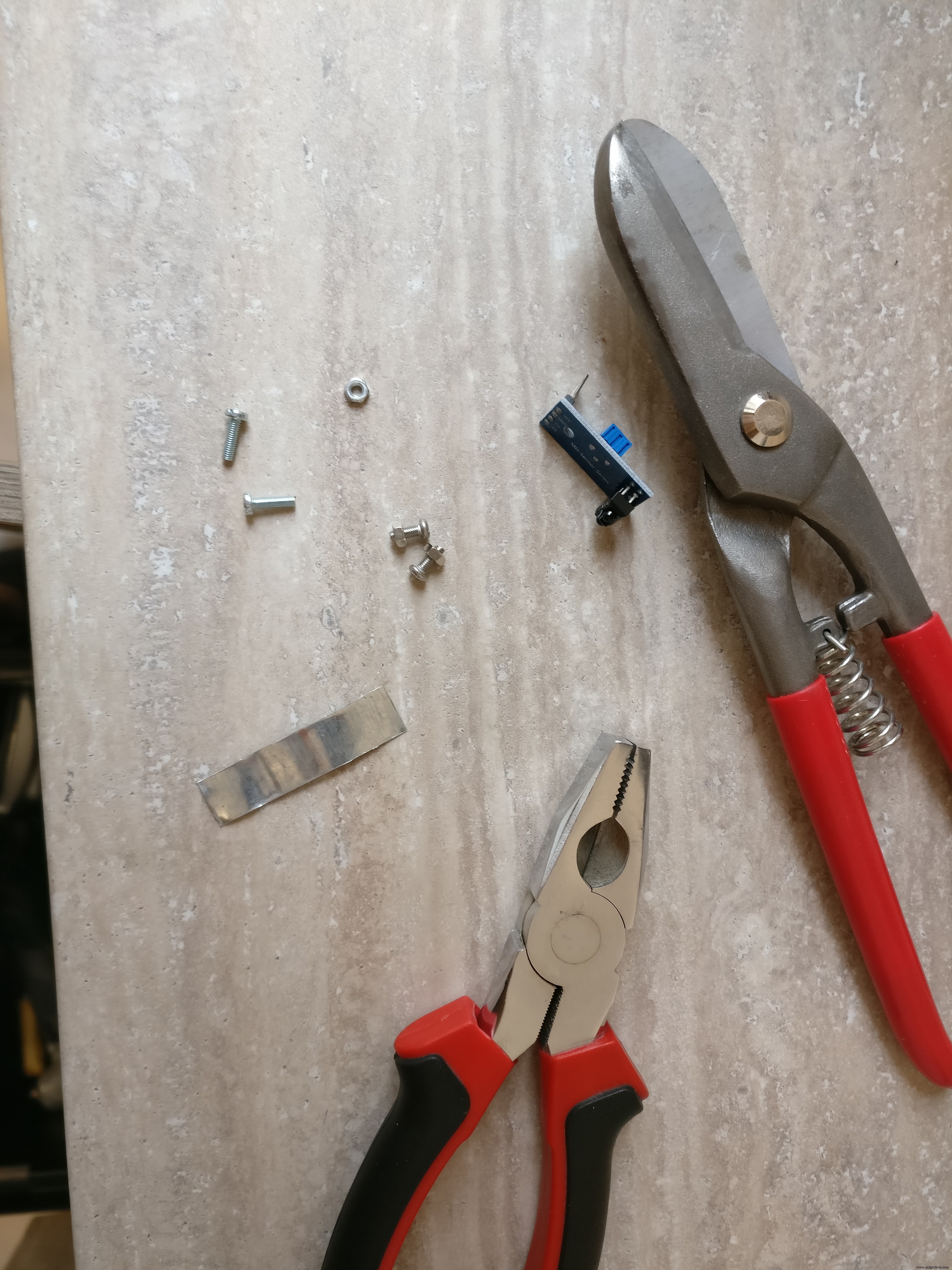
1. 在最后一步中,我们已经在机器人的地板侧安装了 H 桥。我们还需要安装两个红外传感器 一个在前面,一个在后面。我们将使用小金属板将它们安装在底盘上。金属板呈“L”形,有两个孔。我们将使用螺母和螺栓将其安装在底盘上。传感器将位于底盘中间,一个在前,一个在后。
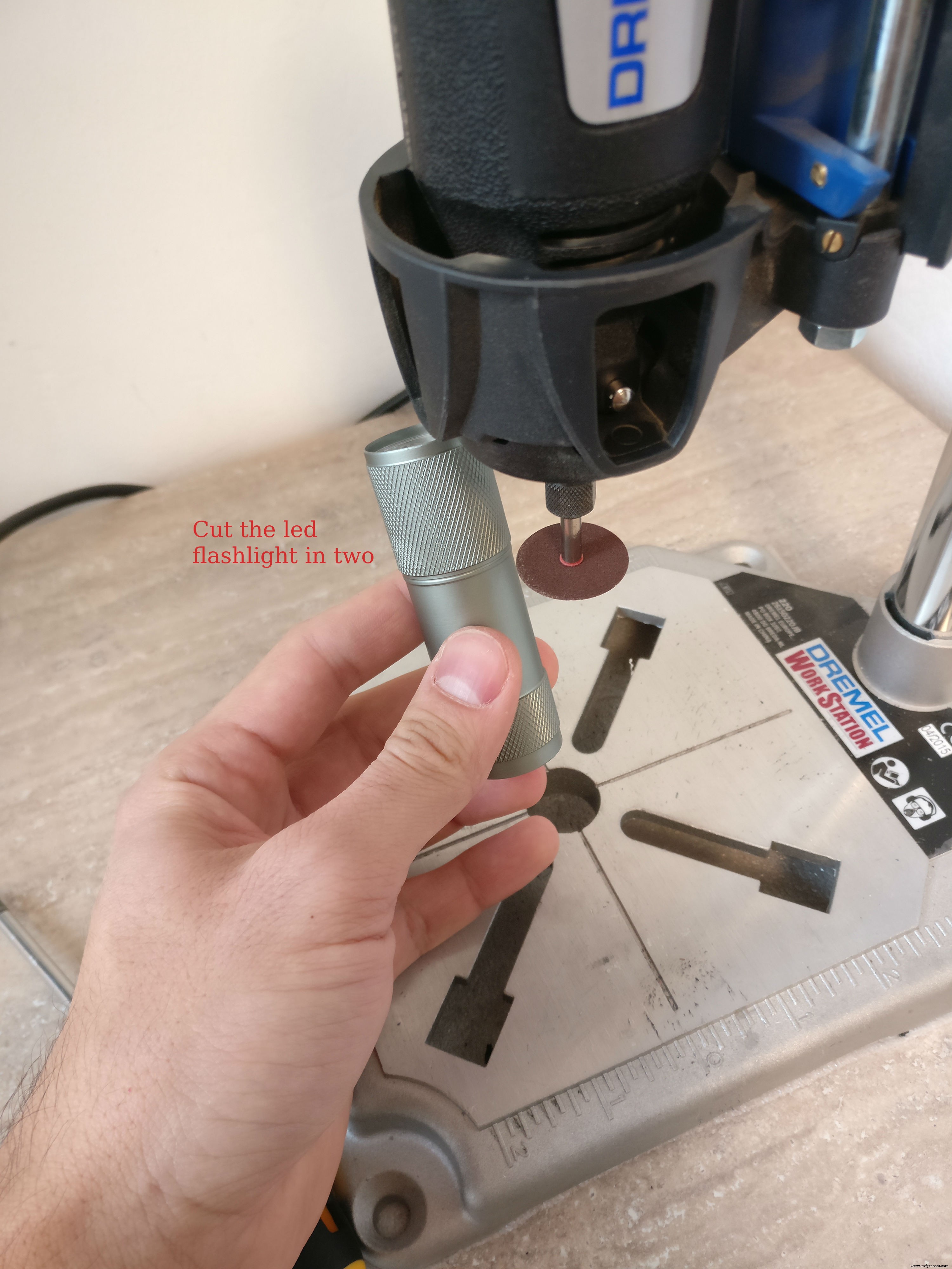
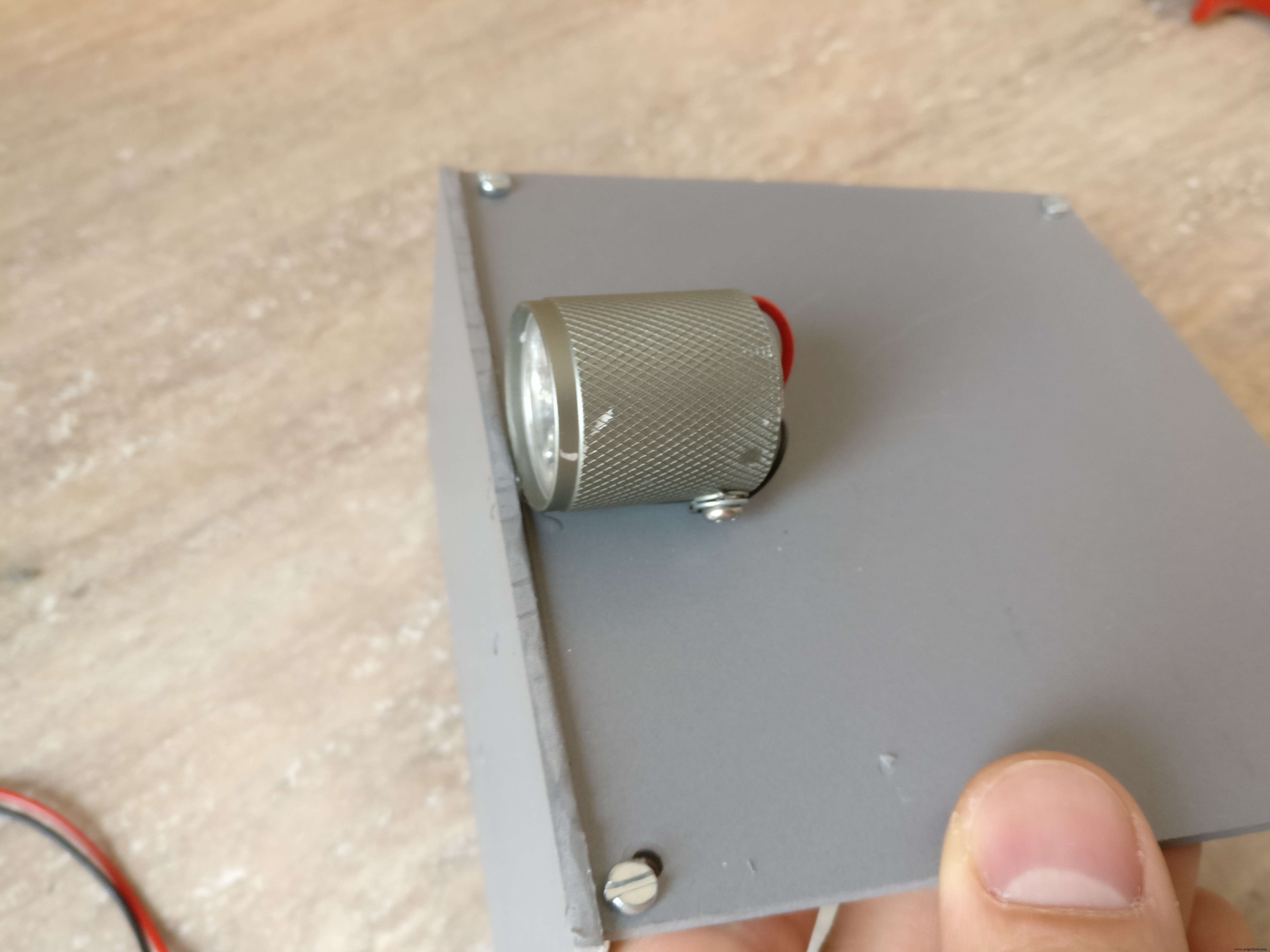
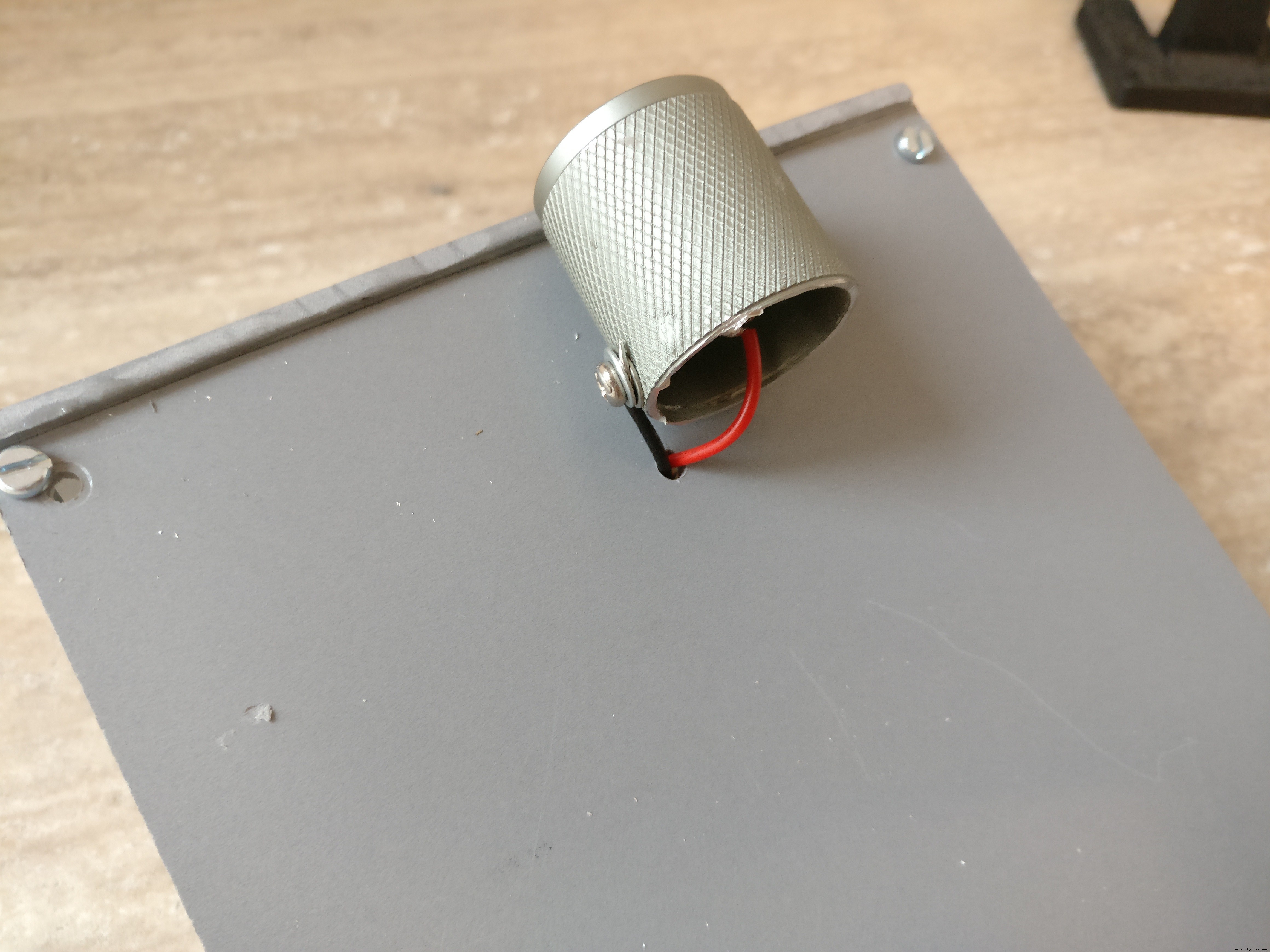
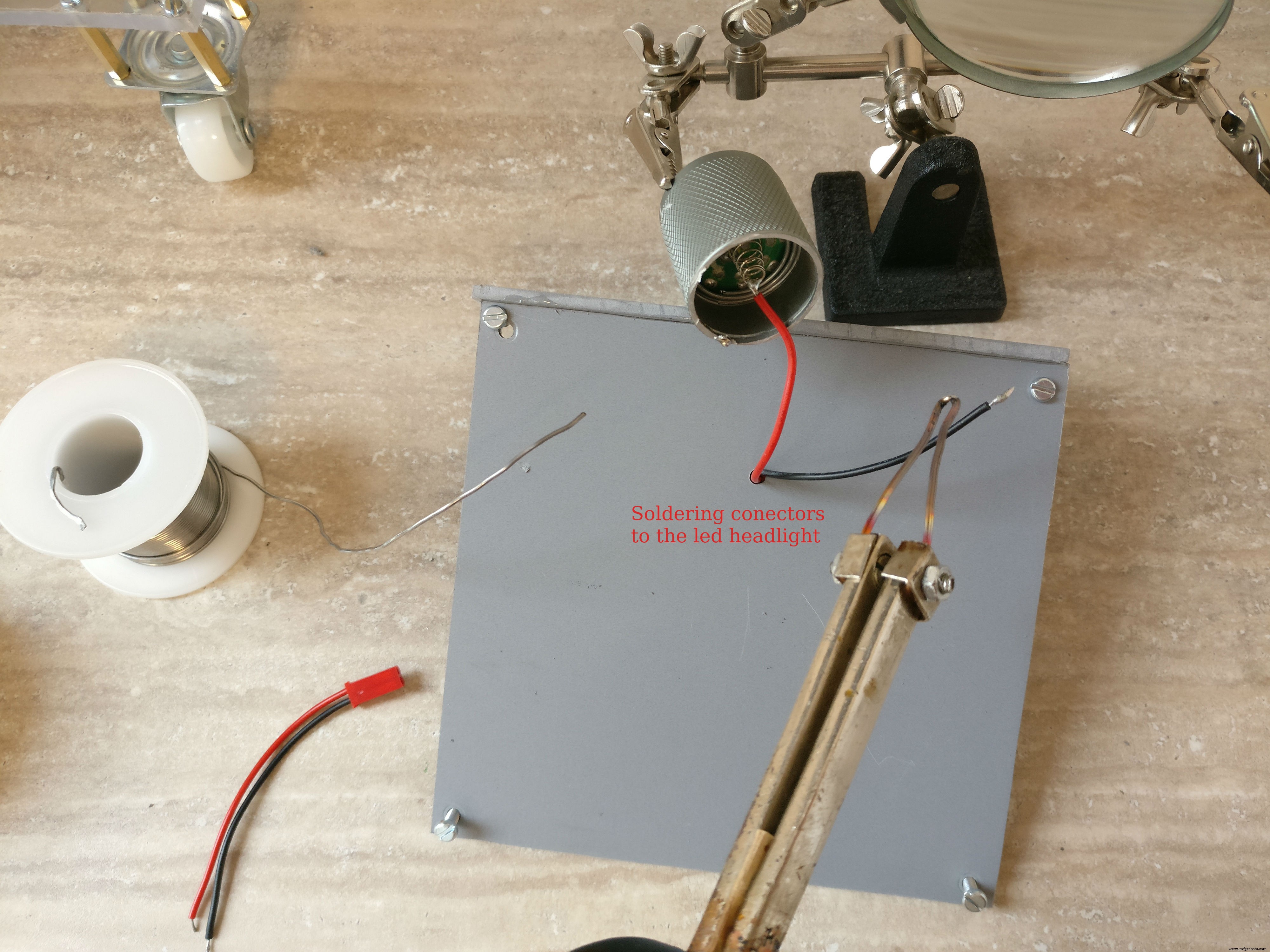
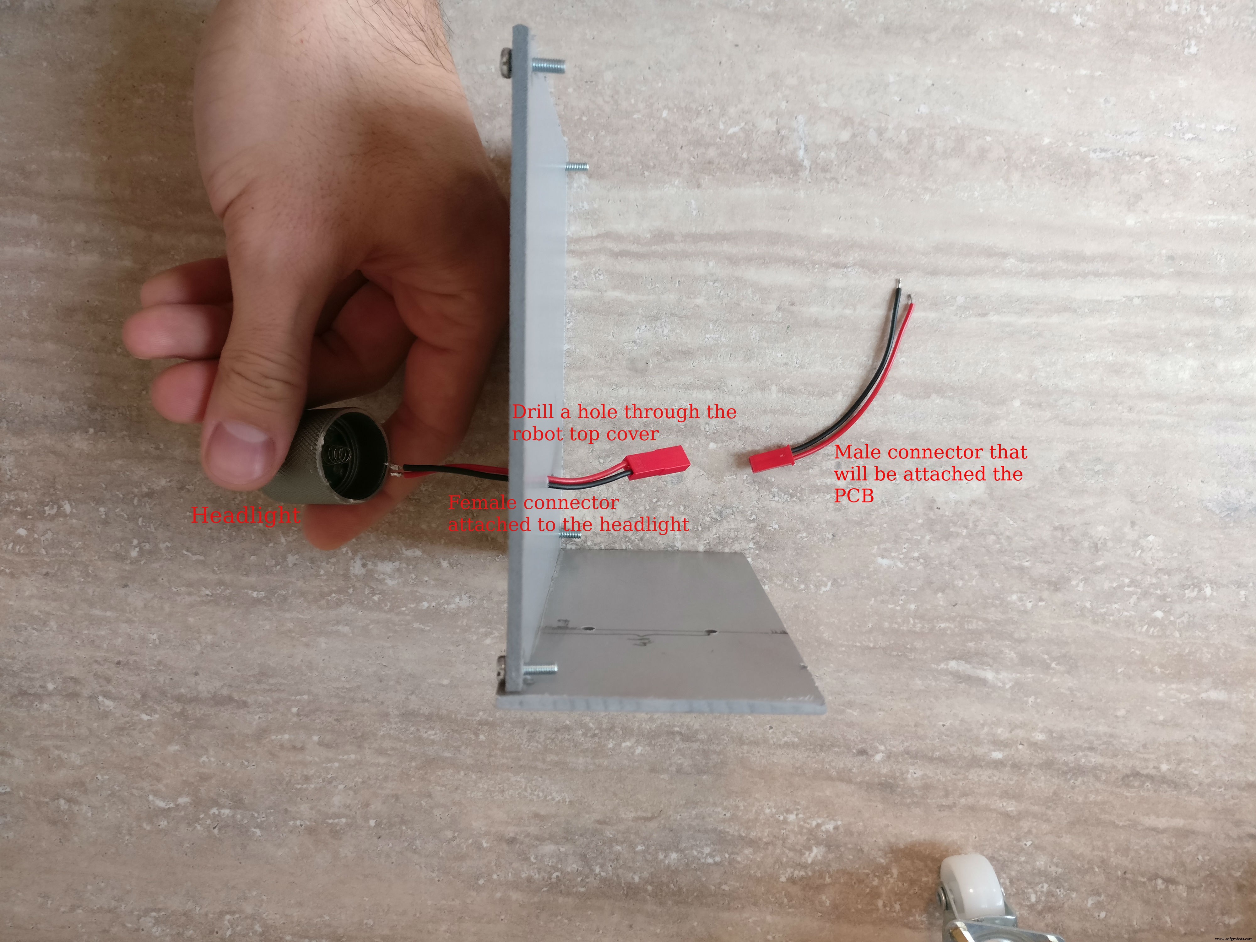
2. 接下来是大灯 部分,为此我使用了 5 伏 LED 手电筒。我切断了只露出“头部”部分的前灯,并焊接了两根电线为其供电。然后我将前灯粘在机器人顶部的中间,并在前灯附近钻了一个孔,将电缆穿过孔并将一个小的母两线连接器焊接到它上面。
3. 组装 树莓派外壳。 您将需要一个树莓派、一个 pi 相机、至少 4 GB 的存储卡、一个 pi 相机连接器。插入安装了最新 Raspian 的卡,然后将 pi 摄像头连接器小心地插入树莓派上,然后将其插入摄像头,然后合上外壳。
如果您不知道如何安装 Raspian 操作系统,请查看此链接。
有关如何安装和启用摄像头的更多信息,请查看这篇官方文章。
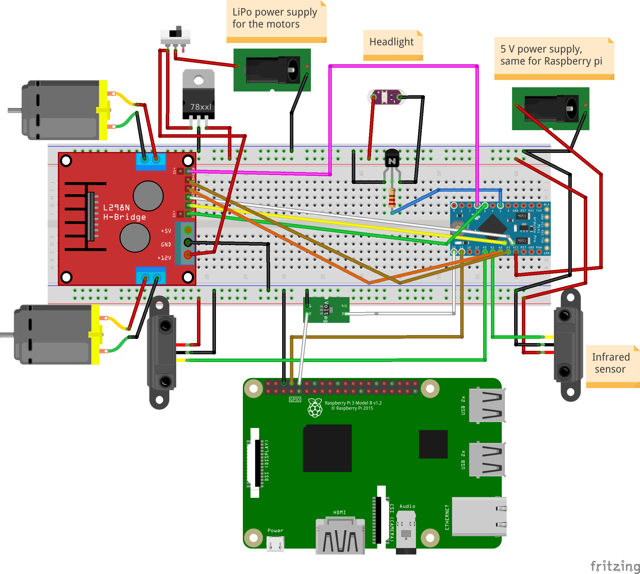
4. 使用主要电子元件构建 PCB。 我附上了 fzz 格式的fritzing 原理图和图片。可以作为参考哦,如何搭建电子设备。
焊接步骤:
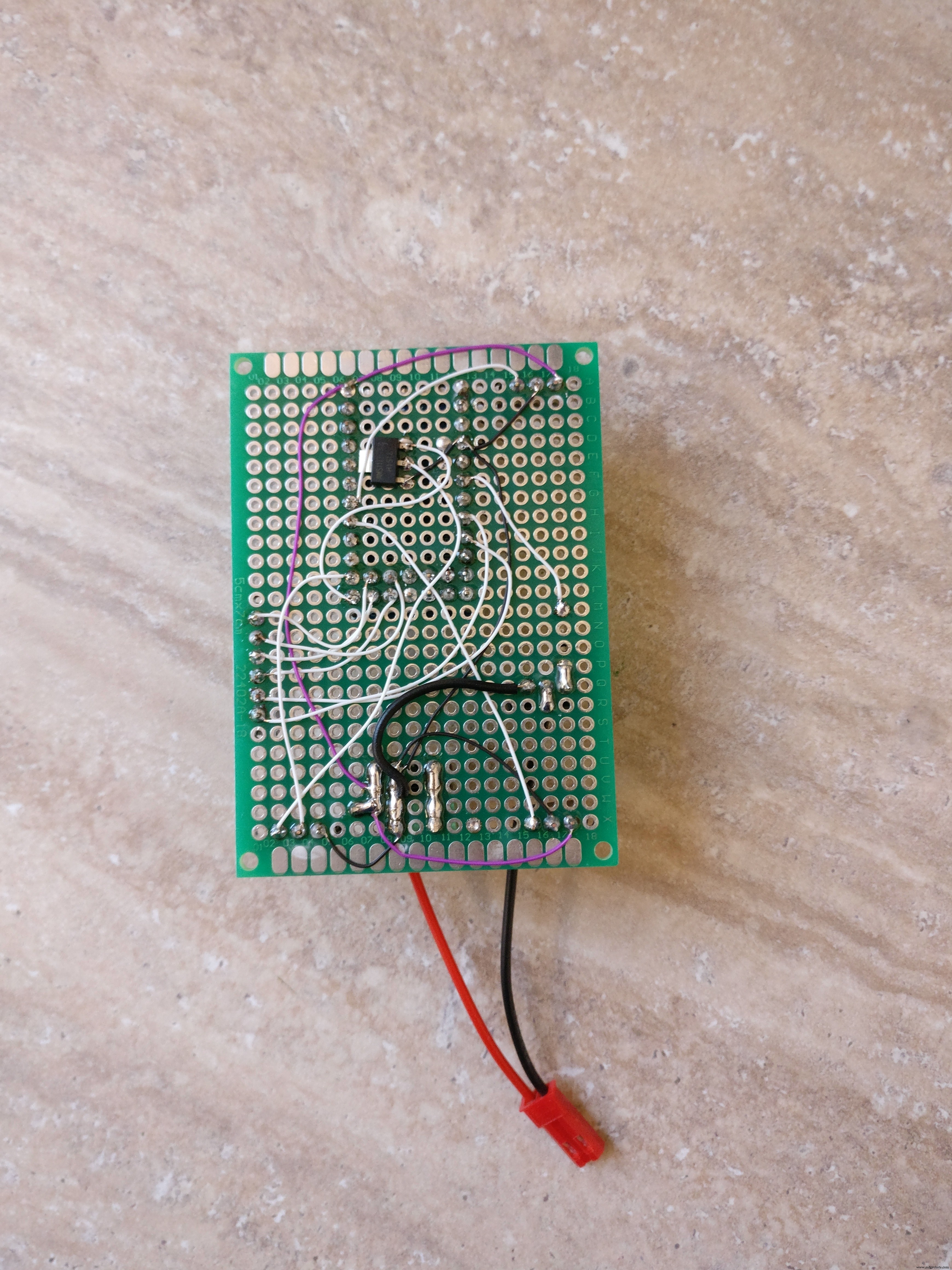
a. 切割母 PCB 连接器,微控制器有两个 12 针连接器和两个 5 针连接器,红外传感器有两个 3 针连接器,H 桥有一个六针连接器,树莓派通信有一个针连接器(地面,TX,RX)b. 在所有连接器都被切断后,必须焊接在 PCB 背面
c. 焊接KF301-2P连接器
d. 将 NPN 晶体管和相应的电阻焊接到它的基极
e. 焊接 L7805CV 5V 稳压器
f. 焊接 3.3 伏稳压器 在arduino转树莓派TX线上
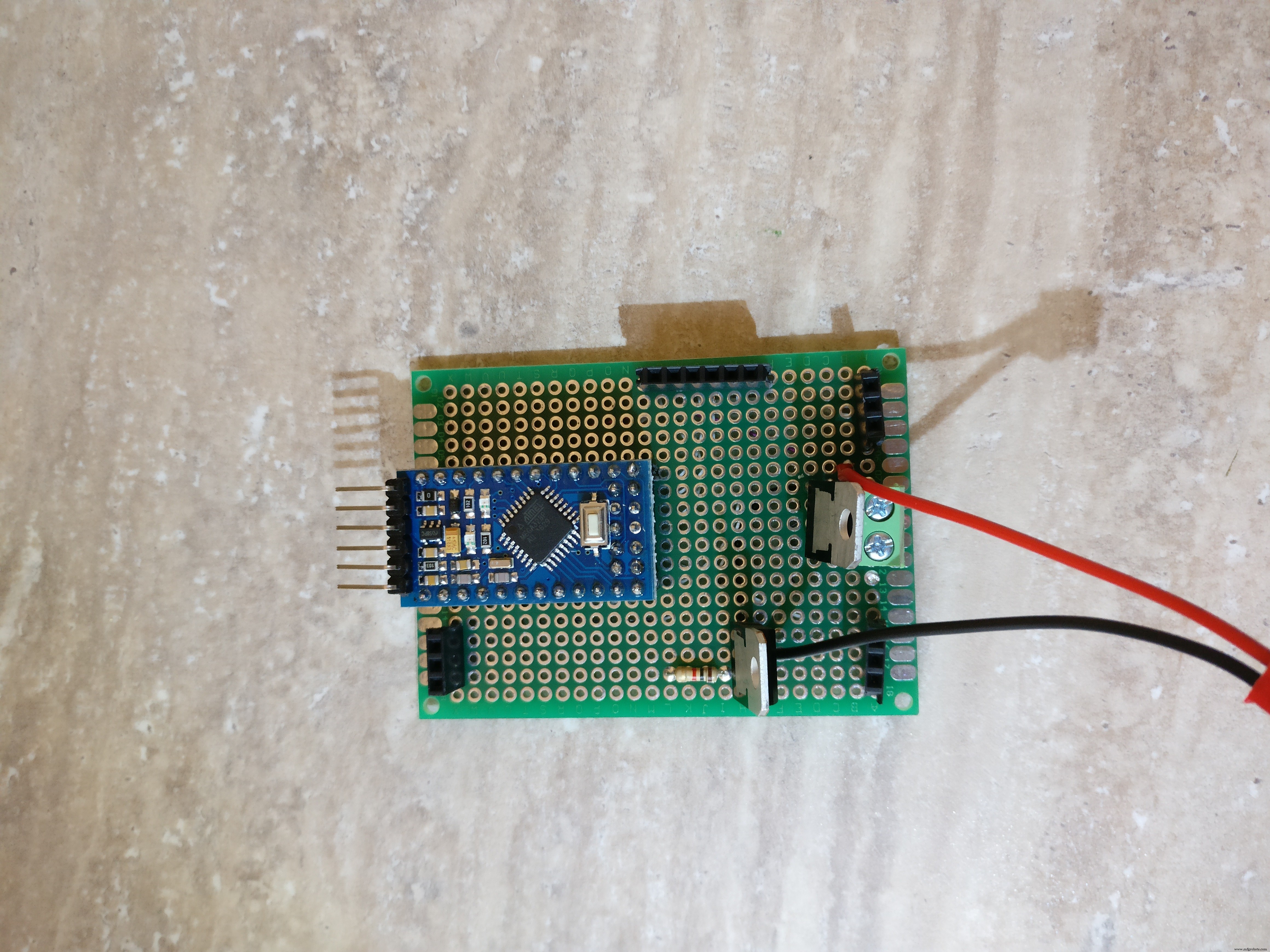
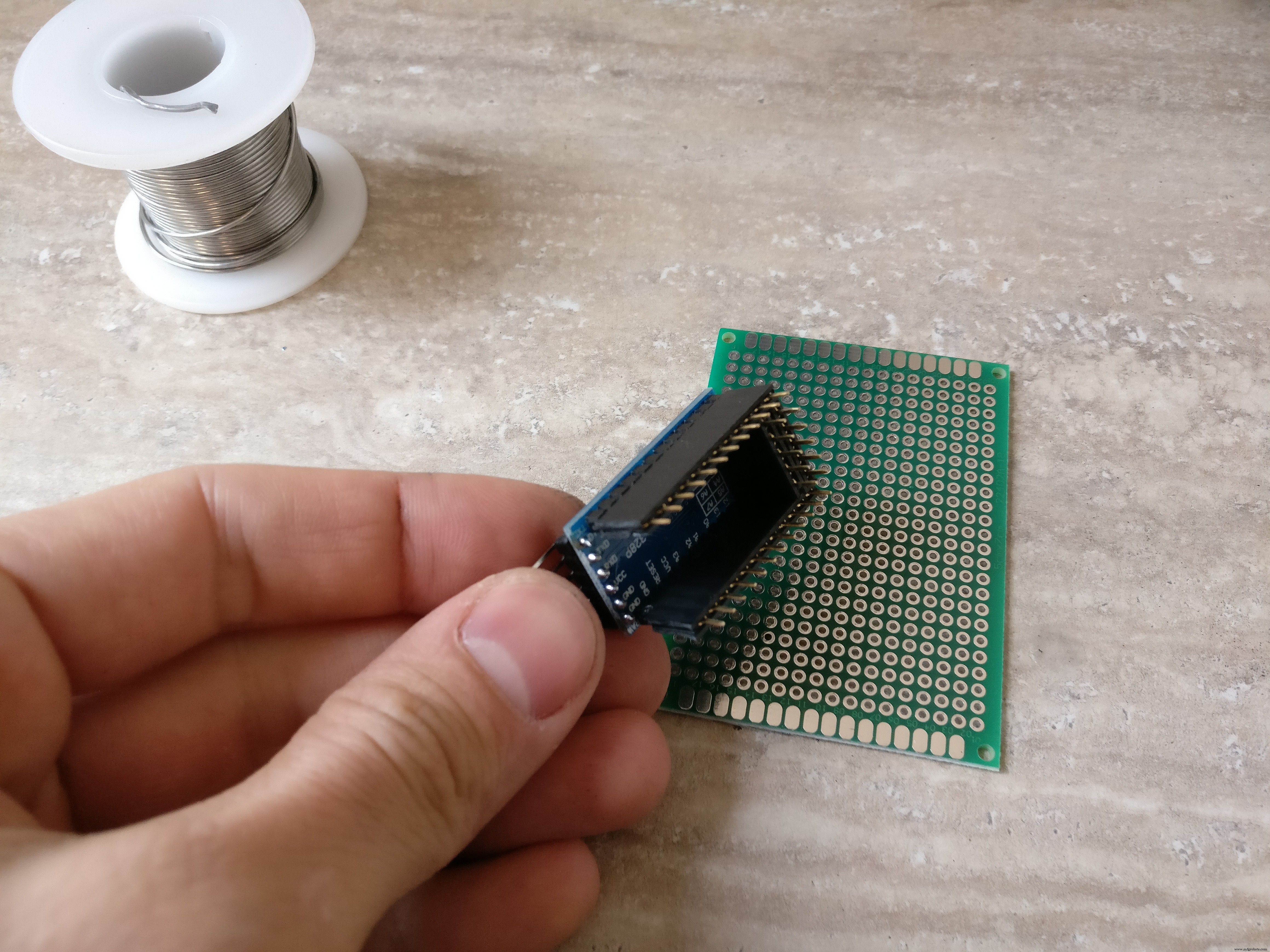
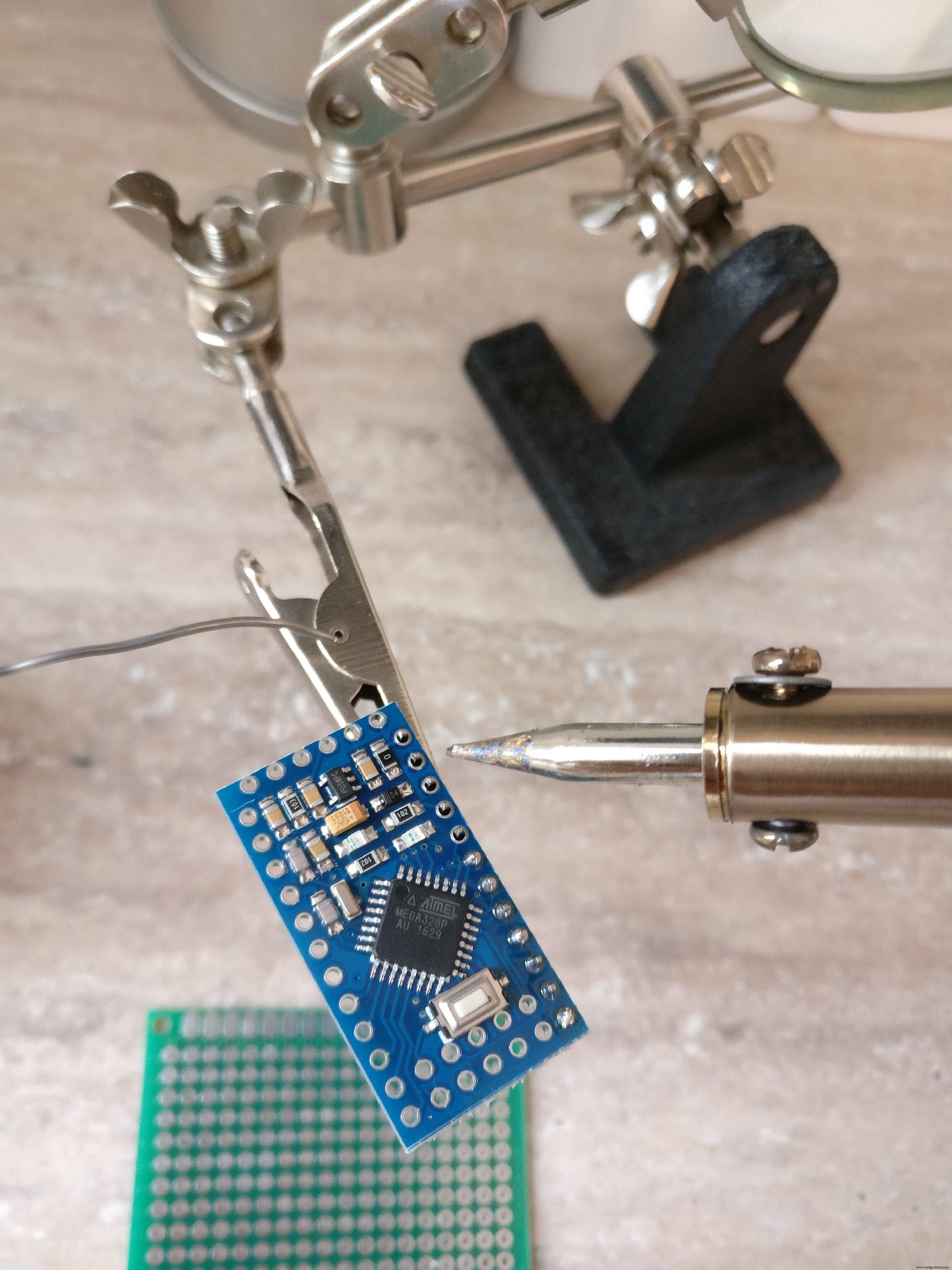
g. 将公针焊接到 arduino pro mini
h。 根据fritzig原理图焊接所有红色(+),黑色(-)和白色(信号)细线
我。 将公连接器焊接到手电筒的面包板上
5.连接器
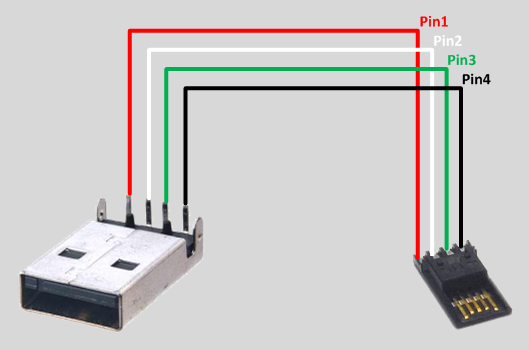
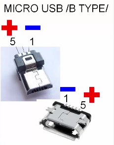
a. 构建从 5V USB 电池组到 raspberry pi 和 arduino 的连接器,您将需要一个 A 型 USB 公连接器、一个黑色和红色电线公微型 USB 连接器、热缩管和一个母对母面包板连接器。首先将母对母连接器一分为二,这些部分将进入 arduino 负极和正极公针。 A 型 USB 连接器将使用微型 USB 连接器向 arduino 和树莓派供电。检查焊接 USB 提示的图像。
b. 构建连接器 将 LiPo 电池连接到电子板,您需要一个 XT-60 女性 LiPo 连接器、红色和黑色电线、热缩管和一个能够处理 10 A 的小开关。黑色电线将直接从 XT-60 连接到电子板(KF301-2P插入式螺丝连接器),红线将通过小开关连接
c. 使用母-公面包板连接器将机器人的两个红外传感器连接到 PCB 上相应的母连接器
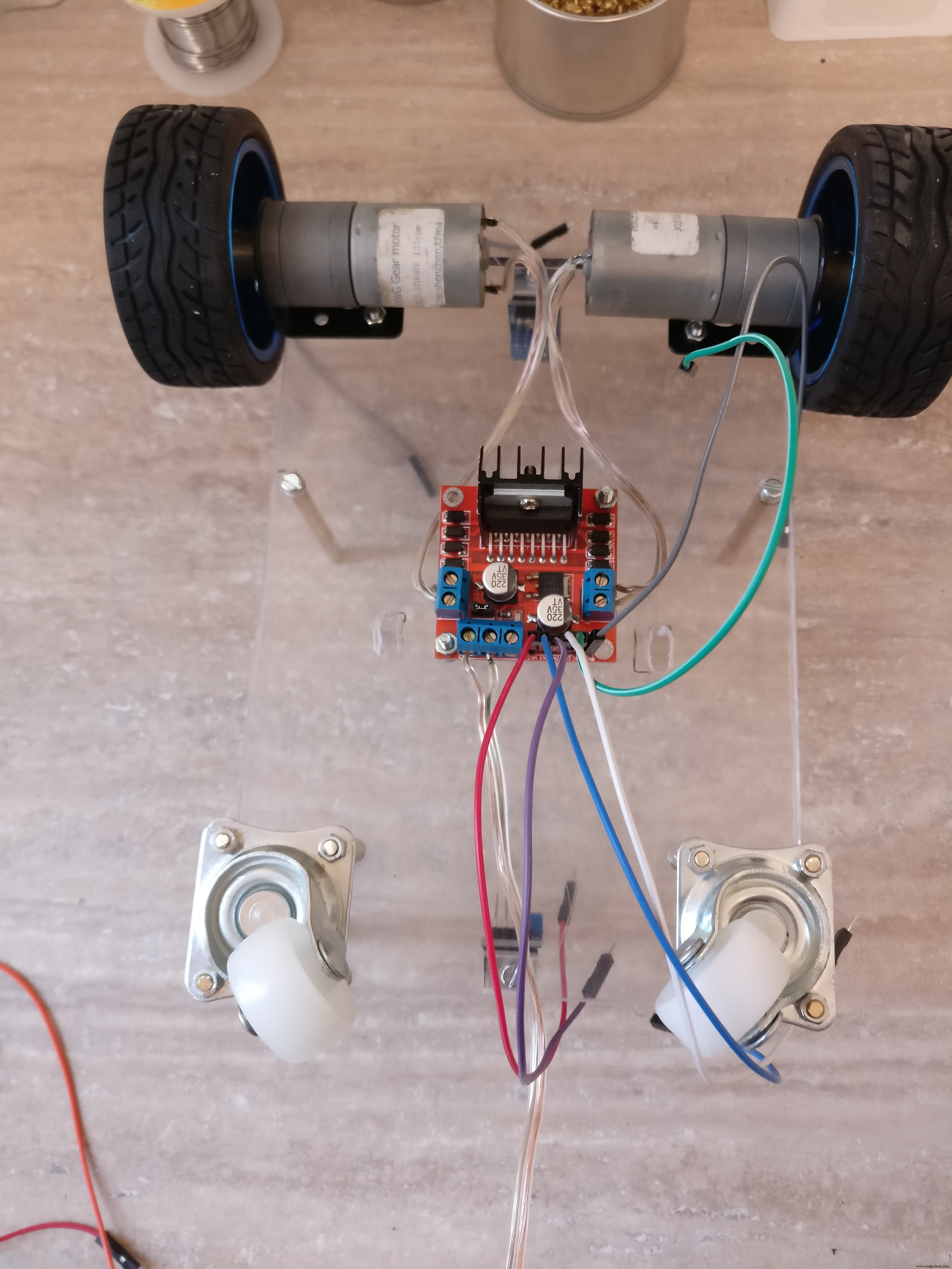
d. 使用公-母面包板连接器将 H 桥连接到 6 针母连接器和 PCB
e. 将电机正负端子连接到 H 桥
f. 将H桥主电源连接到PCB上的KF301-2P插入式螺丝连接器
6. 在将 arduino 放置到 PCB 之前,使用放大镜和万用表仔细检查一切
第 4 步:Arduino 代码
首先我需要回答一个重要的问题: 为什么必须存在中间 arduino 层而不是将 Pi 直接连接到电子设备?
1. 它更模块化,你可以在没有PI的另一个项目中重用arduino机器人
2. 为了安全起见,更换 3 美元的 arduino pro mini 比更换 Pi(35 美元)更便宜
3. 一个 arduino,它不像 pi 那样被操作系统打断,所以为电机实现 PWM 控制更有效,每秒轮询前后传感器几次
4. 如果 python 脚本中可能出现错误,机器人可能会一直运行,耗尽电池,如果没有监督,可能会损坏它或着火,在 arduino 草图中,它更可靠,因为它不依赖于操作系统
5. 解耦系统更容易调试
好的,我已经介绍了为什么部分,我将解释一下 arduino 草图。它基本上做了两件事:
1. 它接收 电机和灯光命令 从串行线驱动电机或切换灯
例如:
* "M:-25:16; " 表示(-25 左),和(16 次方),它将转化为左电机 17% 和右电机 32%,方向向前 * "M:44:19; " 表示 (44 向右) 和 (19 次方) 它将转换为:左马达 38%,右马达 5% 和方向前进
* "L:1; " 表示灯和 "L:0 " 灯灭
2. 它轮询红外传感器 从机器人的后面和前面,发送有关距离的数据 通过串口线
首先你需要下载并安装这个库:
主要代码位于这里的github仓库,或者您可以从下面复制粘贴。
使用 FTDI 适配器将代码上传到 arduino。现在您可以向机器人发出命令以查看它的工作,为此只需连接第二条串行线并通过它发送电机或光。一种方法是使用像 HC-05 这样的蓝牙模块,并使用蓝牙应用程序将其连接到手机。然后给它串行命令,如“L:1”
// TextMotorCommandsInterpretter 的来源:"https://github.com/danionescu0/arduino/tree/master/libraries/TextMotorCommandsInterpretter" #include #include const char MOTOR_COMMAND ='M'; const char LIGHT_COMMAND ='L'; /** * 电机命令在毫秒内生效的时间 * 传入的电机命令将持续 maxDurationForMottorCommand * 如果它不会被另一个电机命令重置 */ const long maxDurationForMottorCommand =300; // 调整这个值来限制机器人速度 const byte maxPwmValue =230; // 以毫秒为单位的连续距离传输之间的间隔时间 const long transmissioningInterval =500; const int maxObstacleDetection =1000; // 模拟读取最大检测值 const int minObstacleDetection =500; // 模拟读取最小检测值 const byte FLASH_PIN =3;常量字节 RIGHT_MOTOR_PWM_PIN =5;常量字节 RIGHT_MOTOR_EN1_PIN =A4;常量字节 RIGHT_MOTOR_EN2_PIN =A5; const 字节 LEFT_MOTOR_PWM_PIN =6; const 字节 LEFT_MOTOR_EN1_PIN =A3; const 字节 LEFT_MOTOR_EN2_PIN =A2; const 字节 FRONT_DISTANCE_SENSOR =A0; const 字节 BACK_DISTANCE_SENSOR =A1;软件串口masterComm(11, 10); // RX, TX TextMotorCommandsInterpretter motorCommandsInterpretter(-50, 50, -50, 50);字符串 currentCommand;长 lastCheckedTime;长 lastTransmitTime;布尔 inMotion =假;无效设置(){ Serial.begin(9600); masterComm.begin(9600); masterComm.setTimeout(10); pinMode(FLASH_PIN, OUTPUT); pinMode(LEFT_MOTOR_PWM_PIN,输出); pinMode(LEFT_MOTOR_EN1_PIN, OUTPUT); pinMode(LEFT_MOTOR_EN2_PIN, OUTPUT); pinMode(RIGHT_MOTOR_PWM_PIN,输出); pinMode(RIGHT_MOTOR_EN1_PIN,输出); pinMode(RIGHT_MOTOR_EN2_PIN,输出); lastCheckedTime =毫秒(); lastTransmitTime =毫秒(); } void loop() { if (masterComm.available()> 0) { currentCommand =masterComm.readString();进程命令(); } if (inMotion &&millis() - lastCheckedTime> maxDurationForMottorCommand) { stopMotors(); } if (millis() - lastTransmitTime>传输间隔) { lastTransmitTime =millis(); masterComm.print(getObstacleData()); Serial.print(analogRead(BACK_DISTANCE_SENSOR));Serial.print("---"); Serial.println(getObstacleData()); } /* FOR DEBUG motorCommandsInterpretter.analizeText("M:-14:40;"); Serial.write("Left==");Serial.println(motorCommandsInterpretter.getPercentLeft()); Serial.write("Right==");Serial.println(motorCommandsInterpretter.getPercentRight()); delay(10000);*/} String getObstacleData() { int frontDistance =analogRead(FRONT_DISTANCE_SENSOR); int backDistace =analogRead(BACK_DISTANCE_SENSOR); frontDistance =map(frontDistance, maxObstacleDetection, minObstacleDetection, 0, 10); backDistace =map(backDistace, maxObstacleDetection, minObstacleDetection, 0, 10); return String("F=" + String(frontDistance) + ":B=" + String(backDistance) + ";"); } void processCommand() { switch (currentCommand.charAt(0)) { case (MOTOR_COMMAND):steerCar();休息;案例(LIGHT_COMMAND):toggleLight(currentCommand.charAt(2));休息; } } void steerCar() { motorCommandsInterpretter.analizeText(currentCommand); float percentLeftMotor =motorCommandsInterpretter.getPercentLeft();浮动百分比RightMotor =motorCommandsInterpretter.getPercentRight(); Serial.write("Left=");Serial.println(percentLeftMotor); Serial.write("Right=");Serial.println(percentRightMotor); setMotorsDirection(motorCommandsInterpretter.getDirection());模拟写入(LEFT_MOTOR_PWM_PIN,percentLeftMotor * maxPwmValue);模拟写入(RIGHT_MOTOR_PWM_PIN,percentRightMotor * maxPwmValue); inMotion =真; lastCheckedTime =毫秒(); } void setMotorsDirection(boolean forward) { if (forward) { digitalWrite(LEFT_MOTOR_EN1_PIN, HIGH);数字写入(LEFT_MOTOR_EN2_PIN,低);数字写入(RIGHT_MOTOR_EN1_PIN,高);数字写入(RIGHT_MOTOR_EN2_PIN,低); } else { digitalWrite(LEFT_MOTOR_EN1_PIN, LOW);数字写入(LEFT_MOTOR_EN2_PIN,高);数字写入(RIGHT_MOTOR_EN1_PIN,低);数字写入(RIGHT_MOTOR_EN2_PIN,高); } } void stopMotors() { Serial.println("停止电机");模拟写入(LEFT_MOTOR_PWM_PIN,0);模拟写入(RIGHT_MOTOR_PWM_PIN,0); inMotion =假; } void toggleLight(char command) { Serial.println("Toggle light"); if (command =='1') { digitalWrite(FLASH_PIN, HIGH); } else { digitalWrite(FLASH_PIN, LOW); } }
第 5 步:安装和配置 Raspberry Pi 项目和依赖项
它是如何工作的:
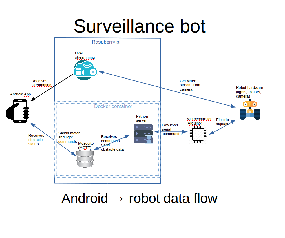
您将在附图中看到我将尝试在上面解释的内容的图表。
a. android 应用程序在 web 视图中显示 uv4l 流。 uv4l 进程在树莓派上运行,捕获来自摄像头的视频输入并将其流式传输。这是一个很棒的工具,具有许多功能
b. 在 android 应用程序中使用控件灯和引擎命令发送到 MQTT 服务器
c. 树莓派上 docker 容器内的 python 服务器侦听 MQTT 命令并使用串行接口将它们传递给 arduino。 arduino 板控制电机和灯。
d. arduino感知机器人前后的距离,通过串口将数据发送到python服务器,python转发给MQTT,由android界面拾取并显示给用户
第一次 您需要在 raspberry pi 上完全安装和配置 Raspbian,并且需要在精神上连接和配置相机。而且所有的配置都将使用ssh完成,所以配置好它是一件好事。
我们无法在此处涵盖所有基本内容,但如有必要,请尝试以下链接:
如果您不知道如何安装 Raspbian 操作系统,请查看此链接。有关如何安装和启用摄像头的更多信息,请查看这篇官方文章。
有关如何在 Raspbian 上配置 ssh,请查看此内容。
如果您希望在 wifi 外部使用 android 应用程序控制您的机器人,您应该考虑在您的 wifi 路由器上进行端口转发,否则您将被限制使用您的 wifi 内部的本地 IP 地址。
要在树莓派上查找本地 IP 地址,请使用“ifconfig”:
ifconfig ..........eth0 Link encap:Ethernet HWaddr b8:27:eb:16:e7:ff inet6 addr:fe80::ff00:f22f:9258:b92b/64 范围: Link UP BROADCAST MULTICAST MTU:1500 指标:1 RX 数据包:0 错误:0 丢弃:0 溢出:0 帧:0 TX 数据包:0 错误:0 丢弃:0 溢出:0 载波:0 冲突:0 txqueuelen:1000 RX 字节:0 (0.0 B) TX bytes:0 (0.0 B) ........ wlan0 Link encap:Ethernet HWaddr 00:c1:41:00:10:f6 inet addr:192.168.0.102 Bcast:192.168.0.255掩码:255.255.255.0 inet6 addr:fe80::e1f4:5112:9cb2:3839/64 Scope:Link UP BROADCAST RUNNING MULTICAST MTU:1500 Metric:1 RX 数据包:1678396 错误:0 丢弃:0 帧溢出:0 超时数据包:381859 错误:0 丢弃:0 溢出:0 载波:0 冲突:0 txqueuelen:1000 RX 字节:259428527 (247.4 MiB) TX 字节:187573084 (178.8 MiB) ..... 我们对 wlan0 inet addr 感兴趣,在我们的例子中是“192.168.0.102”
要转发的端口(默认)是:9090 用于 uv4l,1883 用于 mosquitto。如果这些端口被 Internet 提供商防火墙或其他一些端口禁止,您可以将此端口转发到相同的输出端口。
端口转发是在每个路由器上做的不同的事情,这里有一些教程:这个,你也可以尝试在谷歌上搜索“port forwarding your_router_model " 以查看更多相关结果。
先决条件:
a. 使用命令行安装git
b. 在home文件夹中克隆github项目:
文件夹位置很重要,因为在 docker-compose.yml 中,位置被硬编码为:/home/pi/robot-camera-platform:/root/debug 如果您需要更改位置,请更改 docker-compose 中的值也是
git clone https://github.com/danionescu0/robot-camera-platform.git C。禁用 pi 的串行控制台,如果您不知道如何操作,请查看此链接
安装 Uv4l 流媒体:
chmod +x uv4l/install.sh chmod +x uv4l/start.sh sh ./uv4l/install.sh 如果此操作失败或您需要了解有关 uv4l 的更多详细信息,请查看本教程。
配置:
a. 通过编辑 uv4l/start.sh 您可以配置视频流的以下方面:密码、端口、帧率、带、高度、旋转和其他一些小方面
b. 编辑 config.py 并替换 password 使用您在 mosquitto 服务器上设置的密码
c. 编辑 docker-container/mosquitto/Dockerfile 并替换这一行
RUN mosquitto_passwd -b /etc/mosquitto/pwfile user your_password 使用您自己的 mosquitto 用户名和密码
d. 编辑 config.py 并替换串口 和你自己的波特率,我建议你保持波特率。如果你想改变它,不要忘记在 arduino-sketch 上编辑它
测试 uv4l 安装 a. 开始吧:
sh ./uv4l/start.sh b. 在浏览器中测试地址:http://your_ip:9090/stream
c. 别了
sudo pkill uv4l
安装 docker 和 docker-compose
关于docker安装:https://www.raspberrypi.org/blog/docker-comes-to-...
关于docker-compose安装:https://www.raspberrypi.org/blog/docker-comes-to-...
重新启动/启动时自动启动服务
通过使服务自动启动,您将无需通过 ssh 手动登录然后手动激活所有服务,我们将使用 systemctl 来完成此操作。
a. 将 systemctl 文件夹中的 systemctl 文件夹中的文件复制到 /etc/systemd/system/
b. 启用服务
sudo systemctl enable robots-camera.service sudo systemctl enable robots-camera-video.service c. 重启
d. 可选,检查状态:
sudo systemctl status robots-camera.service sudo systemctl status robots-camera-video.service
第 6 步:配置和构建 Android 应用程序
我们都大功告成了,在这一步中,我们将安装 android 应用程序。这些都是先决条件:
1. 克隆github项目:
git clone https://github.com/danionescu0/android-robot-camera The next steps involves setting up your environment, i'll just enumerate them and give a link to a specialized tutorial, in case you don't know how to do it.
2. Enable developer options on your android phone. You can find out more here:https://developer.android.com/studio/debug/dev-opt...
3. Download and install Android studio:https://developer.android.com/studio/index.html?ut... and this https://www.javaworld.com/article/3095406/android/...
4. Import project :https://developer.android.com/studio/intro/migrate...
Now we're going to configure the the streaming and MQTT credentials:
5. Edit ./app/src/main/values/passwords.xml and configure MQTT and streaming
The MQTT host should be something like:1883
The streaming host should be something like:
6. Upload and run the application
Step 7:Using the Robot and Debugging
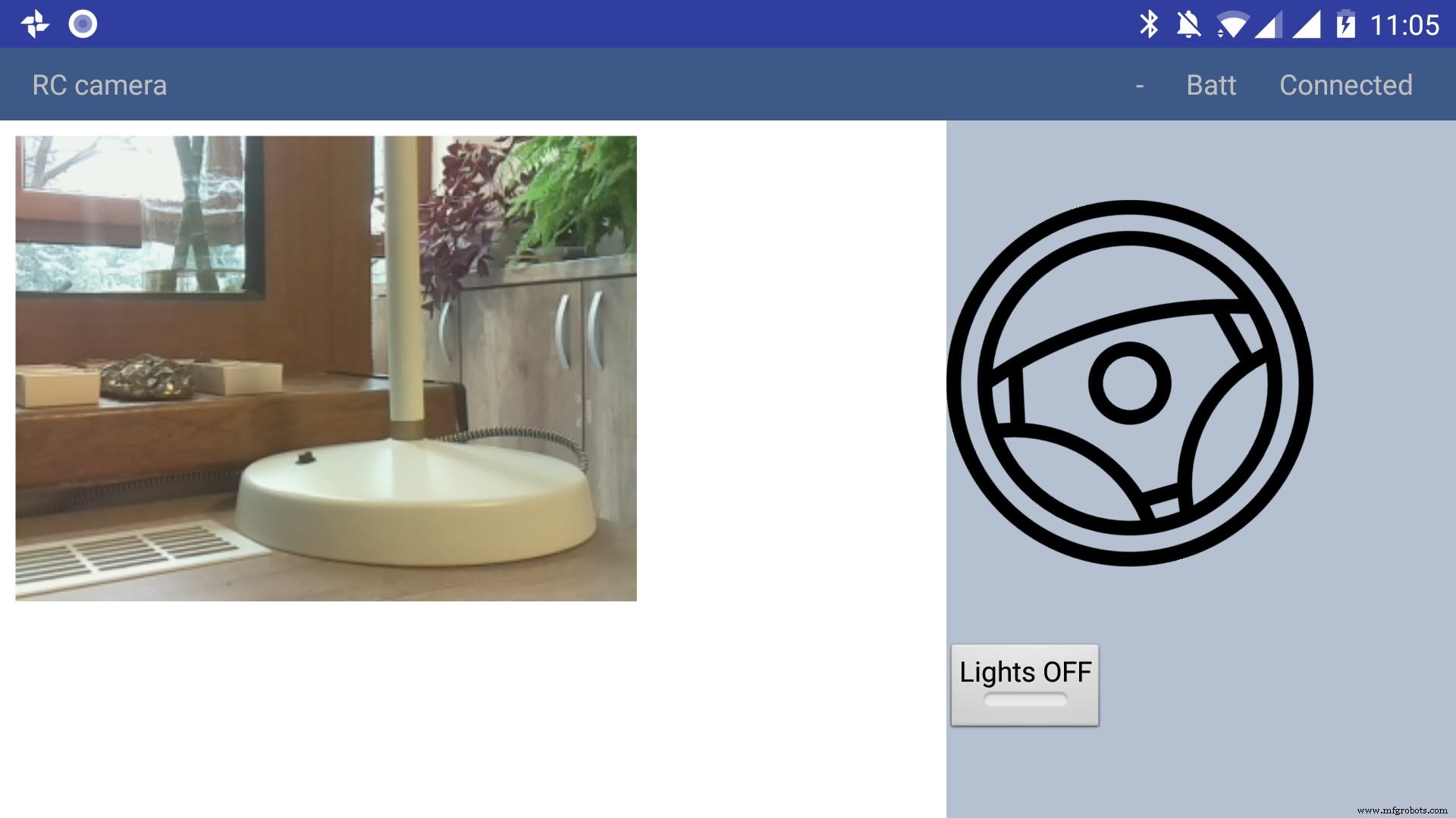
Using the app
The application has only a main screen, in the left of the screen the streamming image is displayed. On the right
there are the controls. The main control is a steering wheel, touch the steering wheel in the direction you wish the robot to move. Below the steering wheel there is a headlight button, touch it to toggle the light.
In the top right corner there is a text like :"- Batt Connected".
* First dash means no obstacles, if there is an obstacle in front or in the back of the robot it will be signaled with a small arrow pointing in front or in the back.
* The "Batt" status is not implemented yet.
* "Connected" means that MQTT server is connected so the robot can be used, the other possible value is "Disconnected"
Debugging can be done on multiple layers:
1. On the arduino layer
- Connect the FTDI adapter to the second serial line to the laptop (RX to pin 11 and TX to pin 10) and issue motor commands and light commands to see if the robot responds to these commands
- Double check the connections, if the motors are moving backwards reverse the both motor wires, if one motor is moving backwards reverse the it's wires
- Check if the arduino is connected properly to the H-bridge, check this link for more information
2. On the rasberry pi layer
- Check docker is running the two containers (mosquitto and python server)
pi@raspberrypi:~ $ docker ps CONTAINER ID IMAGE COMMAND CREATED STATUS PORTS NAMES 473a56da2230 dockercontainer_python-server "python /root/debu..." 9 months ago Up 4 hours dockercontainer_python-server_1 3e0b1933d310 robot-camera-mosquitto "/usr/bin/entry.sh..." 9 months ago Up 4 hours 0.0.0.0:1883->1883/tcp dockercontainer_mosquitto_1 - Check the processes are running on specified ports, you should look for 9090 (streamming) and 1883 (mosquitto)
pi@raspberrypi:~ $ netstat -nltp (Not all processes could be identified, non-owned process info will not be shown, you would have to be root to see it all.) Active Internet connections (only servers) Proto Recv-Q Send-Q Local Address Foreign Address State PID/Program name tcp 0 0 0.0.0.0:9090 0.0.0.0:* LISTEN - tcp 0 0 0.0.0.0:5900 0.0.0.0:* LISTEN - tcp 0 0 0.0.0.0:8080 0.0.0.0:* LISTEN - tcp 0 0 0.0.0.0:22 0.0.0.0:* LISTEN - tcp6 0 0 :::1883 :::* LISTEN - tcp6 0 0 :::5900 :::* LISTEN - tcp6 0 0 :::22 :::* LISTEN - - Check the serial port exists (it's the correct one) and it's specified in the project config.py
pi@raspberrypi:~ $ ls -l /dev/ttyS0 crw-rw---- 1 root dialout 4, 64 Jan 14 19:59 /dev/ttyS0 - Stop the docker process and manually connect to serial using picocom
Then issue motor and light commands directly to see if the robot responds
sudo systemctl start robot-camera.service picocom -b 9600 /dev/ttyS0 # now issue motor and light commands to test the robot - Check if the serial console is deactivated on the raspberry pi
- Check the streaming and MQTT are accessible outside the raspberry pi suing a mosquitto client (for MQTT) and checking the streaming in a web browser)
3. Android application layer
- Check all the necessary steps to enable the phone into debugging mode (check this out)
- Make sure you've set up the passwords and endpoints correctly in the passwords.xml
- Check the streaming and MQTT are accessible outside the raspberry pi suing a mosquitto client (for MQTT) and checking the streaming in a web browser)
- See the top right corner of the app and check for "Connected"
- Use the android debugger to check for errors
Step 8:Other Use Cases, Extending the Code
Another use case is a object following robot .The robot will follow an object of a specific color and size threshold
Check above for the video.
Because this is out of scope of this tutorial i'll just give you some hints:
First install dependencies using pip, the installation process will be quite slow
sudo pip3 install -r /home/pi/robot-camera-platform/navigation/requirements.txt - make sure python 3.x is installed though
- In navigation/config_navigation.py you'll find:
hsv_bounds =( (24, 86, 6), (77, 255, 255) ) object_size_threshold =(10, 100) HSV means hue saturation value, and for our color object detection to work it has a lower and an upper bound, our object color will have to be in this range to be detected. Here you can find a visual HSV object threshold detector.
Object size threshold means the smallest and the highest object radius size (in percents from width) which will be considered a detection.
- install and configure VNC (more information of how to install VNC here)
- Run the object tracking script in VNC graphical interface in a terminal. This will enable you to view the video, with a circle drawn over it. The circle means that the object has been detected.
python3 object_tracking.py colored-object --show-video OR Run the object tracking script with no video output:
python3 object_tracking.py colored-object I think the main advantage of this platform is versatility , it can be adapted easily to other interesting usages, some of my ideas:
- Following a person by face recognition
- Patrolling and reporting movement
- Replace the wifi with a 3G modem and the robot can be controlled outside, maybe exploring dangerous zones
This being a very complex project i assume that there will be errors, i will appreciate if you ask me anything in the comments area.
If you like my project please my youtube channel for more interesting stuff.
代码
Android application
https://github.com/danionescu0/android-robot-cameraMain repository for arduino, python code
https://github.com/danionescu0/robot-camera-platform示意图
sketch_nWf7cZeUWL.fzzMain repository for arduino, python code
The main repositoryhttps://github.com/danionescu0/robot-camera-platformAndroid application
https://github.com/danionescu0/android-robot-camera制造工艺