

自己种植 | GIY
组件和用品
 |
| × | 1 | |||
 |
| × | 1 | |||
 |
| × | 1 | |||
 |
| × | 4 | |||
 |
| × | 1 | |||
 |
| × | 1 | |||
 |
| × | 1 | |||
 |
| × | 1 | |||
 |
| × | 1 | |||
 |
| × | 1 |
必要的工具和机器
| |
| |||
| |
|
应用和在线服务
 |
| |||
 |
|
关于这个项目
简介
在观看了由麻省理工学院开放农业计划主任 Caleb Harper 发表的关于数字农业的 TED 演讲后,我受到了极大的启发,该演讲提出了以下主题:这台计算机将在未来种植你的食物 .他在演讲中提出的最重要的问题真正激发了我的灵感,如果我们能在世界任何地方的室内种植美味、营养丰富的食物会怎样?这个想法诞生了!
所以,我想做的是像盒子或孵化器这样的东西,它能够创造生长所需的理想气候条件,准确提供植物所需的光和养分。我想将阳光模拟器、灌溉系统和气候控制器整合到一个优雅而现代的设计中。

我计划通过实施以下技术来达到预期的结果:
种植 LED 灯 - 植物中的叶绿素主要只对两种波长有反应,分别为 450nm 和 650nm。我计划使用的 LED 系统将结合使用红色和蓝色 LED 灯,以提供完美的组合,以帮助植物生长和开花生长。
超声波雾化器 (造雾器)- 我想使用一种新的灌溉方法,我最近为自己发现了这种方法,称为气培法 (FogPonics),通过注入肥料的雾气给植物浇水。
自动营养计量 - 该系统会在植物需要的时候自动为植物提供营养。
水传感系统 - 我想为我的系统配备 pH 和 TDS(总溶解固体)传感器,以帮助保持水库中最适合植物的平衡 pH 值,并了解和提醒何时添加营养。
水交换系统 - 系统应配备自动换水装置。我想让这个过程变得简单,只需点击一个按钮即可控制。
风控系统 - 它允许对系统内部的温度和湿度进行精确控制,低至一个度。背后的技术涉及使用温度/湿度传感器(如 DHT22 或 DHT11)来接收数据,并使用带有线圈的风扇进行相应的调节。
移动应用 - 我真的很想建立我人生中的第一次应用程序!该应用程序应包括有关 pH 值、温度、湿度、营养素、ppm 等的实时信息以及随时间变化的图表表示,以便跟踪统计数据并在社交媒体上分享生长进度。我还想实施智能警报,让我知道系统何时需要我的暗示。我不仅要在手机上接收数据表示,还要能够在系统内设置气候条件!
不幸的是,我不是第一个想出这种想法的人,但想出创意的最好方法是改进现有的!
市场上有几个类似的项目可用,然而,尽管有所有的优点,但它们也有一些缺点,比如占用太多空间或太小、太贵、一次只种植一种作物等。我做了很多仔细研究分析现有项目的优势和劣势,并考虑市场反应,想出一个新的先进的开源系统,减少劣势,只实现最好的功能。
很有野心,不是吗?但是让我们试一试
实验
处理植物是非常耗时的!它们通常需要几周到几个月的时间才能成长,我必须为此做好准备!
因为我已经知道我想要为我的最终项目构建什么,所以我必须提前处理它,不要把一切都留到最后一刻。所以,我会尽快开始测试和实验!
我想知道的第一件事是使用营养丰富的雾种植植物的事实 并种植 LED 灯 在土壤和自然阳光下比传统系统更好!理论上应该是这样的,但我不相信任何东西,直到我尝试过!
所以我决定开始我自己的实验,这需要一些时间,它包括将植物分成几组:
- (土壤 + 阳光) - 这组将在绝对自然的条件下生长,种植在土壤中,并放置在窗台上。
- (雾 + 阳光) - 这组会被放在一个容器里,里面会有营养丰富的雾气,也放在同一个窗台上
- (土壤 + 种植 LED 灯) - 该组将在土壤中,但将使用人造 Grow LED 灯而不是阳光
- (雾 + 生长 LED 灯) - 这应该是HERO group) 因为我未来的系统将实现这两个功能,生长的 LED 灯和营养丰富的云雾,我希望发现这种组合会显示出最好的结果!
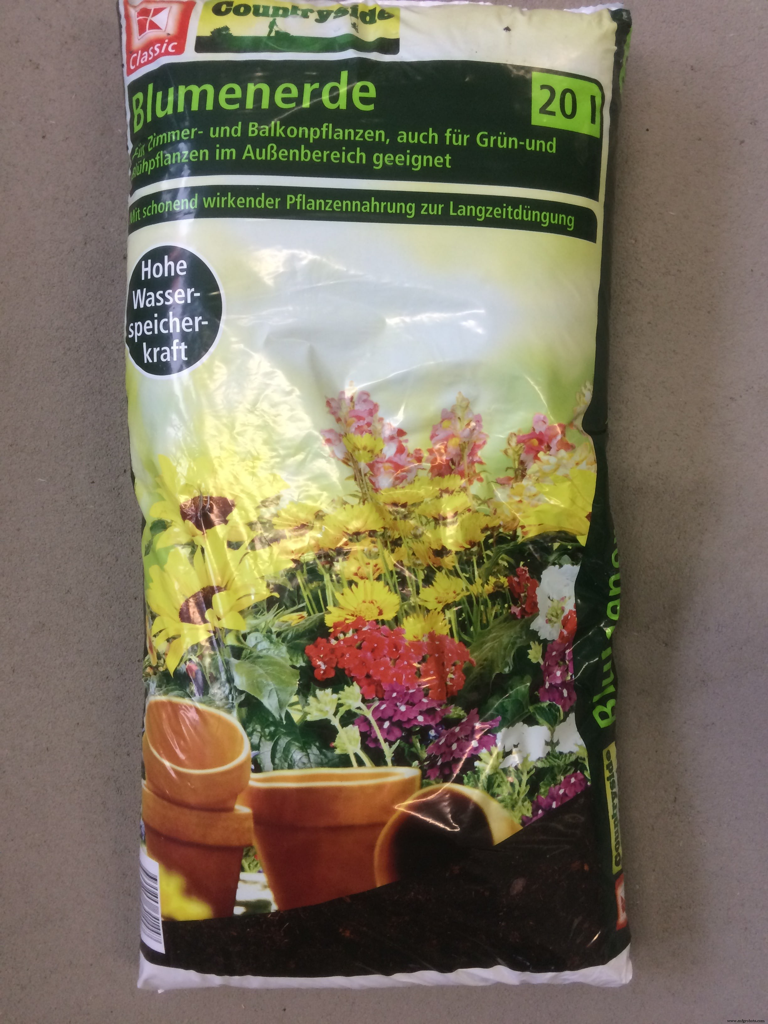
在当地的德国 Kaufland 商店的植物部,我买了混合草药的种子。这些将是我的测试婴儿 :p
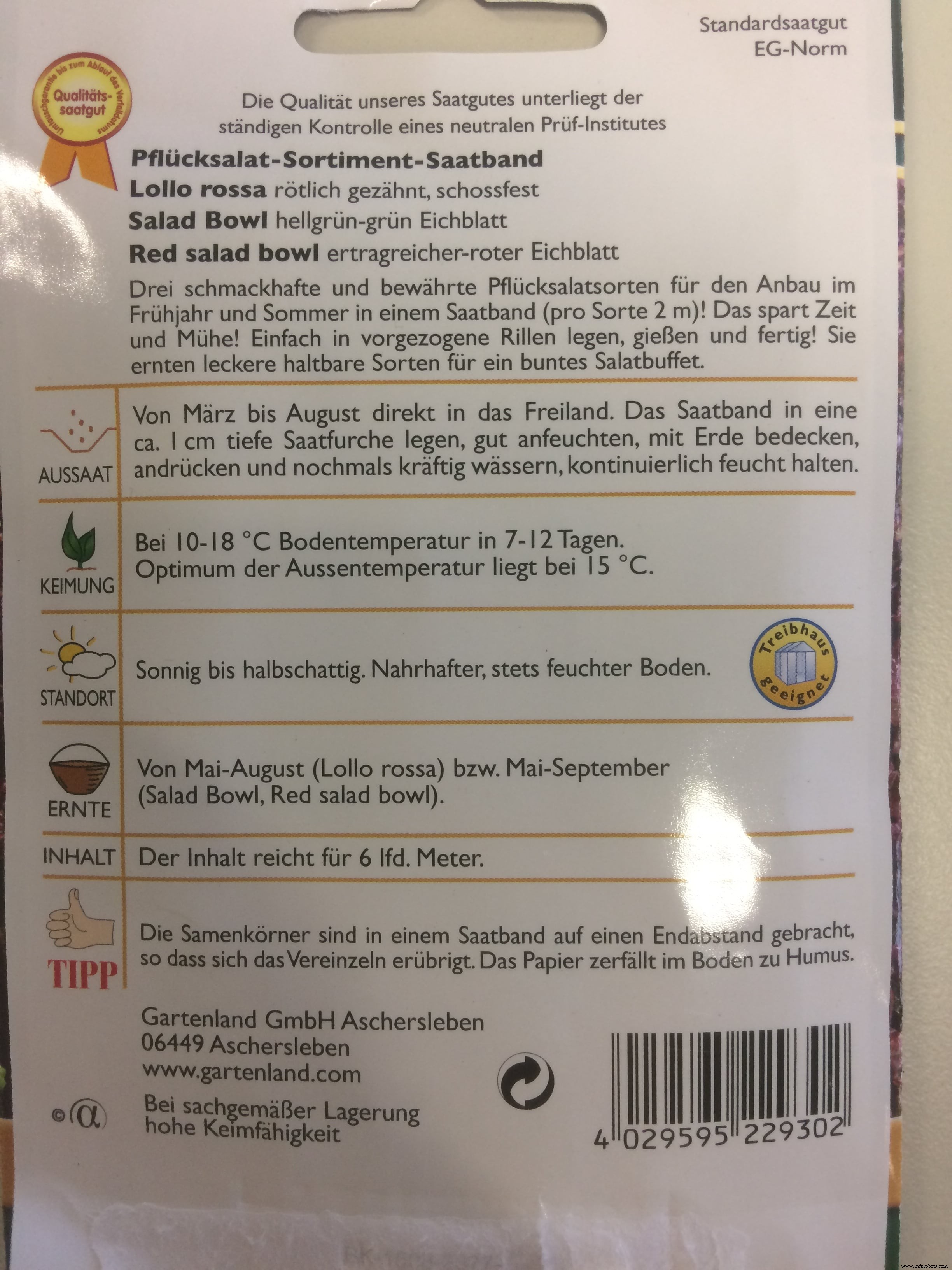
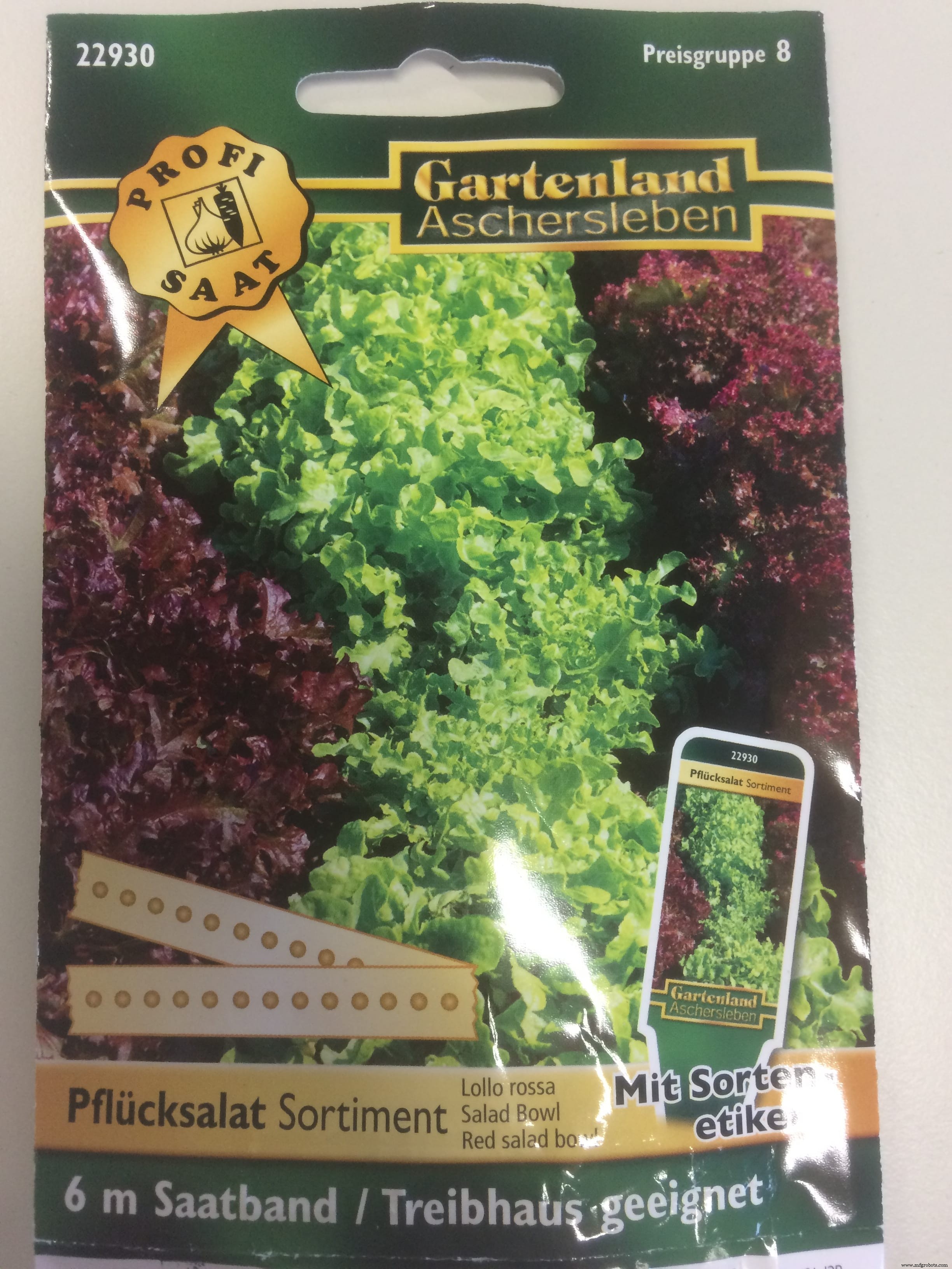
这是我生命中第一次种植任何东西 :D 如果我做错了什么,请不要评判我!)
之前查了几个教程,才知道要先发芽。我有一个塑料容器,我把种子放在那里,然后用纸巾盖住。在这个阶段,他们需要几乎100%的湿度,这就是为什么我用喷雾器给纸巾浇水,并用塑料袋盖住容器,这样水就不会蒸发。
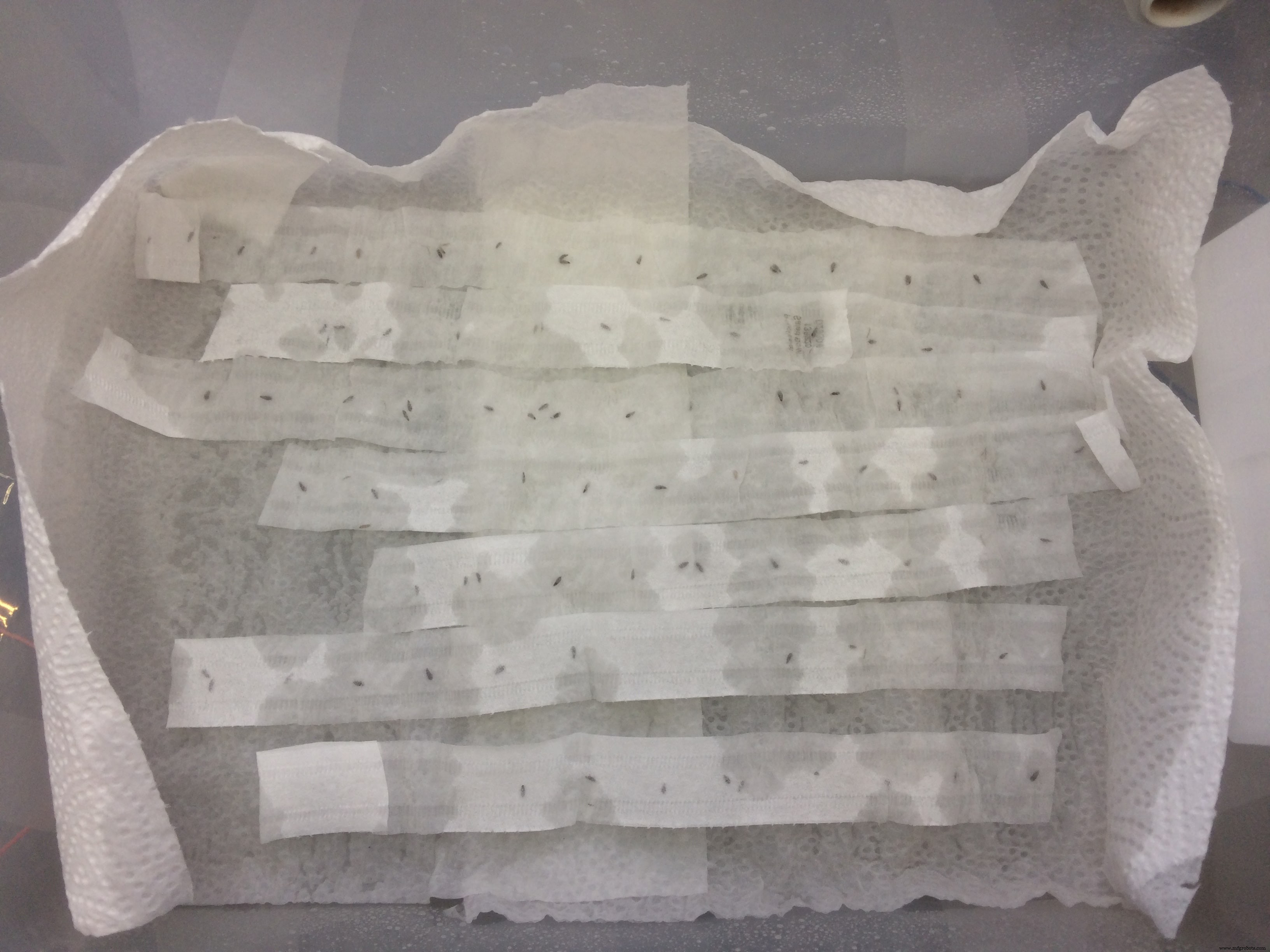
我把种子放了1.5周,打开容器的时候真的很惊喜!
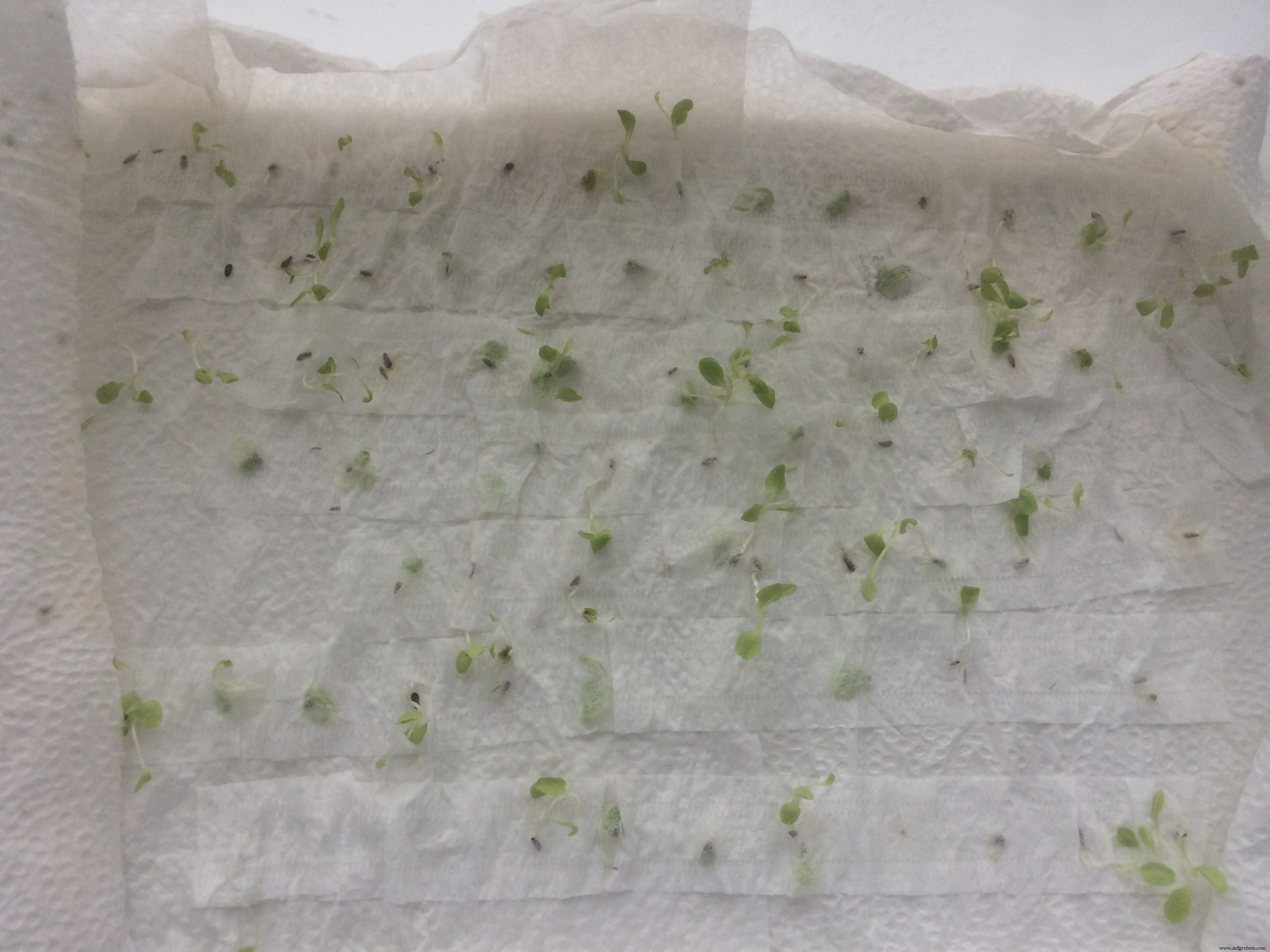
几乎所有的种子都发芽了!我像个孩子一样快乐)
接下来,我必须选择最好的小植物,那些茎最粗的植物,而且整体看起来更大更好。
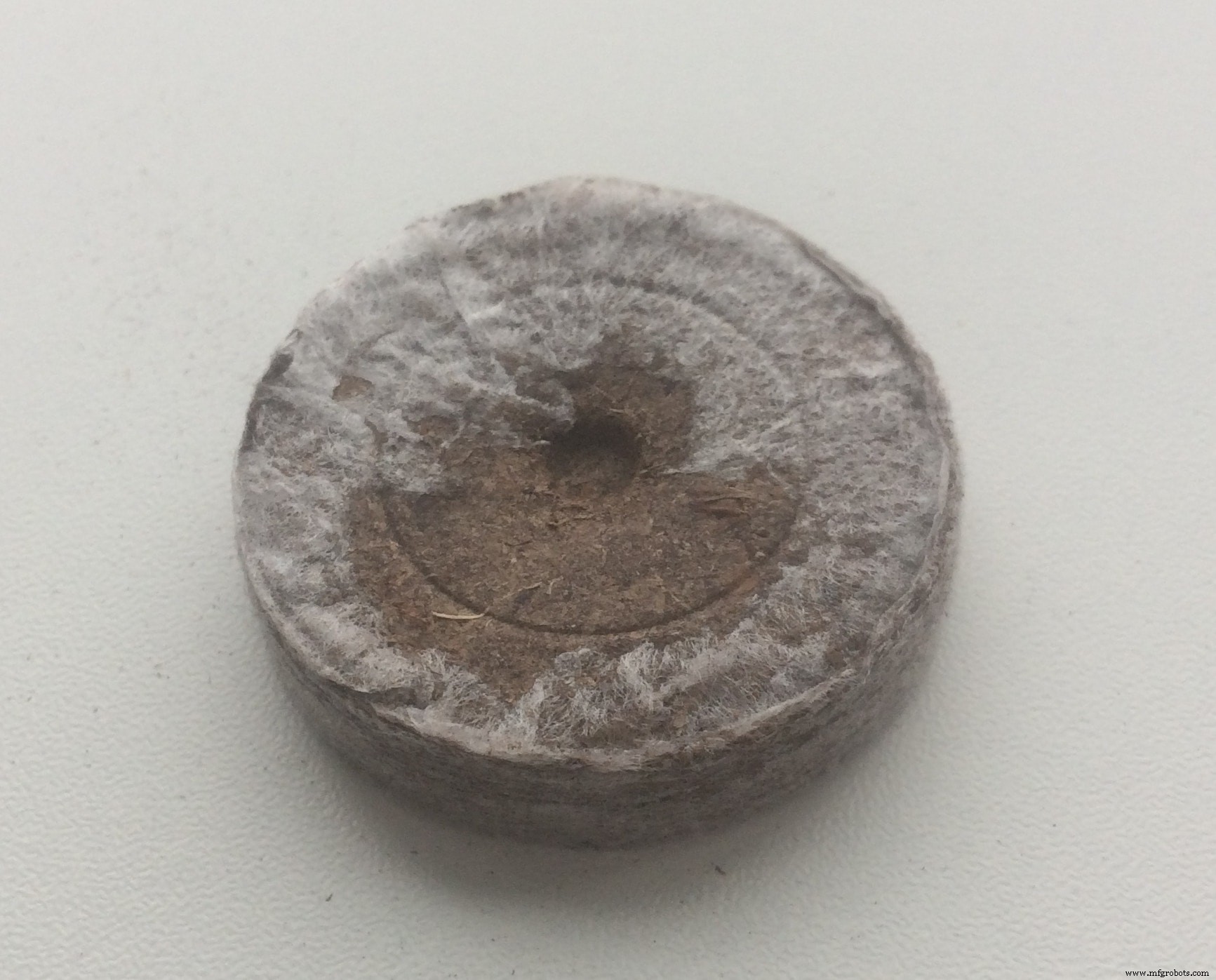
在我关注的教程(YouTube 博主)中,这家伙建议将小植物种植到任何类型的培养基中,直到它们长出所谓的“第二片叶子”。我在亚马逊上订购了椰子椰壳颗粒 .它们是有机的,具有与土壤相似的特性,最酷的是当颗粒被浇水时,它们的尺寸会变大 6 倍。
我还买了一个盒子,里面有种植专用的隔板!我只花了 2 欧元就得到了它,这让事情变得更有条理。我把椰子粒放在盒子的隔板里,给它们浇水直到它们完全水合,把小植物放在中间,然后用盒子套件附带的透明塑料片盖住盒子。
我的小温室长这样:
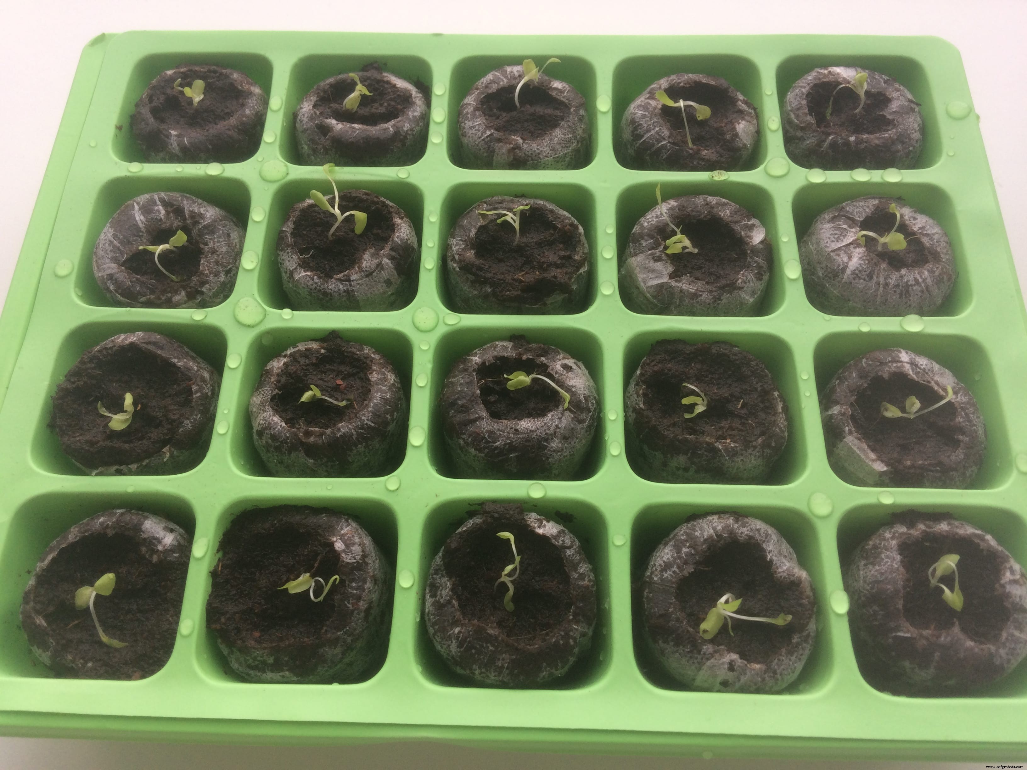
我关上盒子,放了一个星期!
当我再次打开它时,我很惊讶!他们居然变大了!我无法想象我可以设法种植一些植物,我几乎无法照顾自己 :D
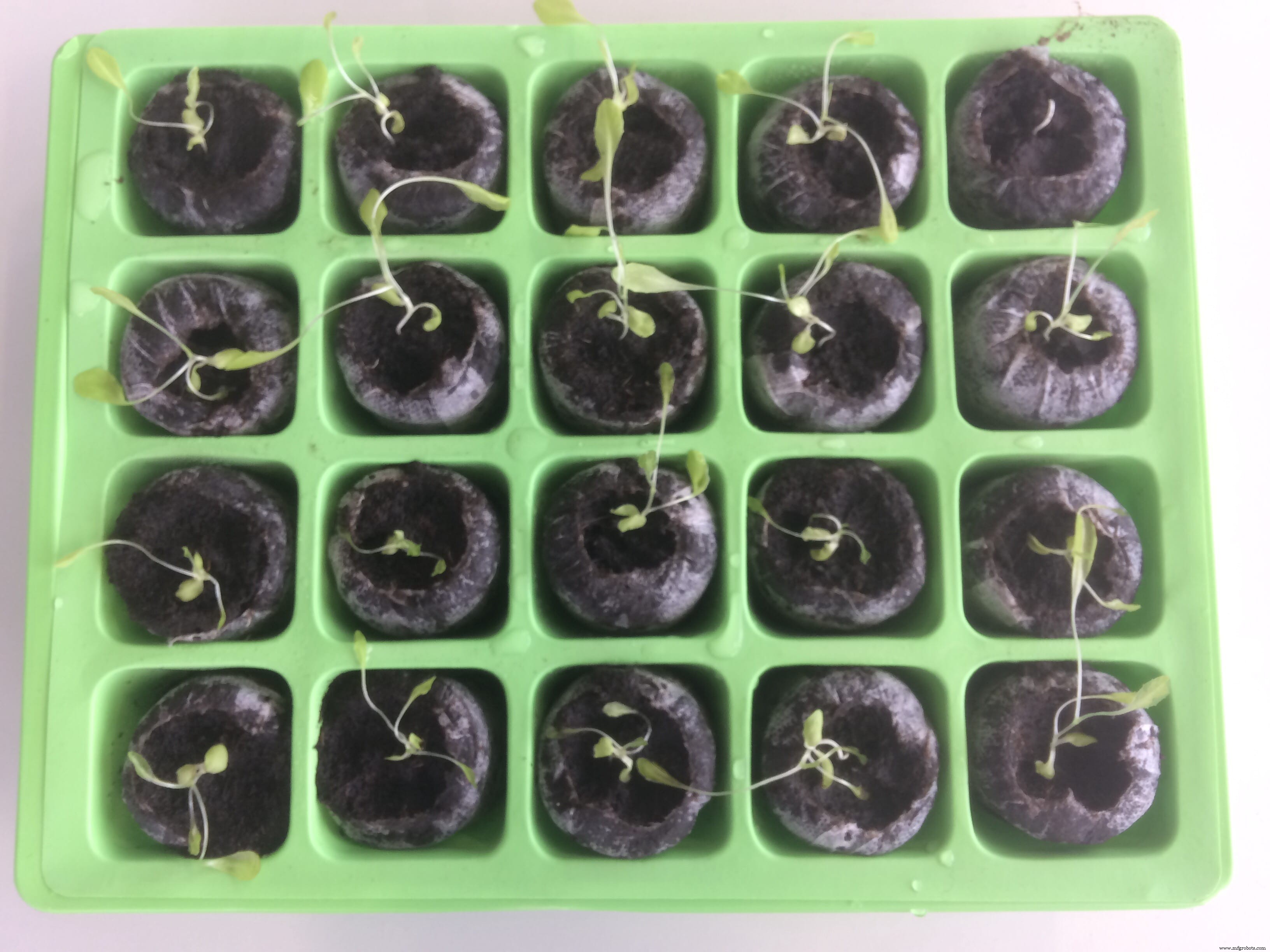
一星期后,差别就很明显了!
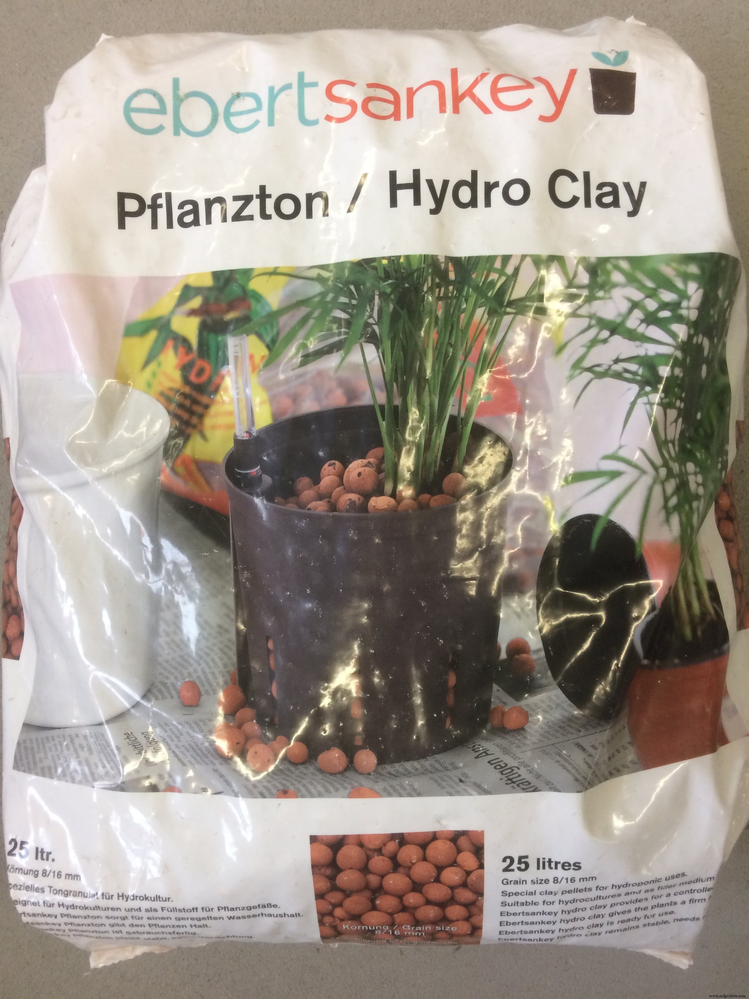
现在当我看到第一个根时,我可以将它们放在土壤和粘土球中,然后开始尝试雾!
在计算机辅助设计周期间,我设计了用于放置植物的网杯
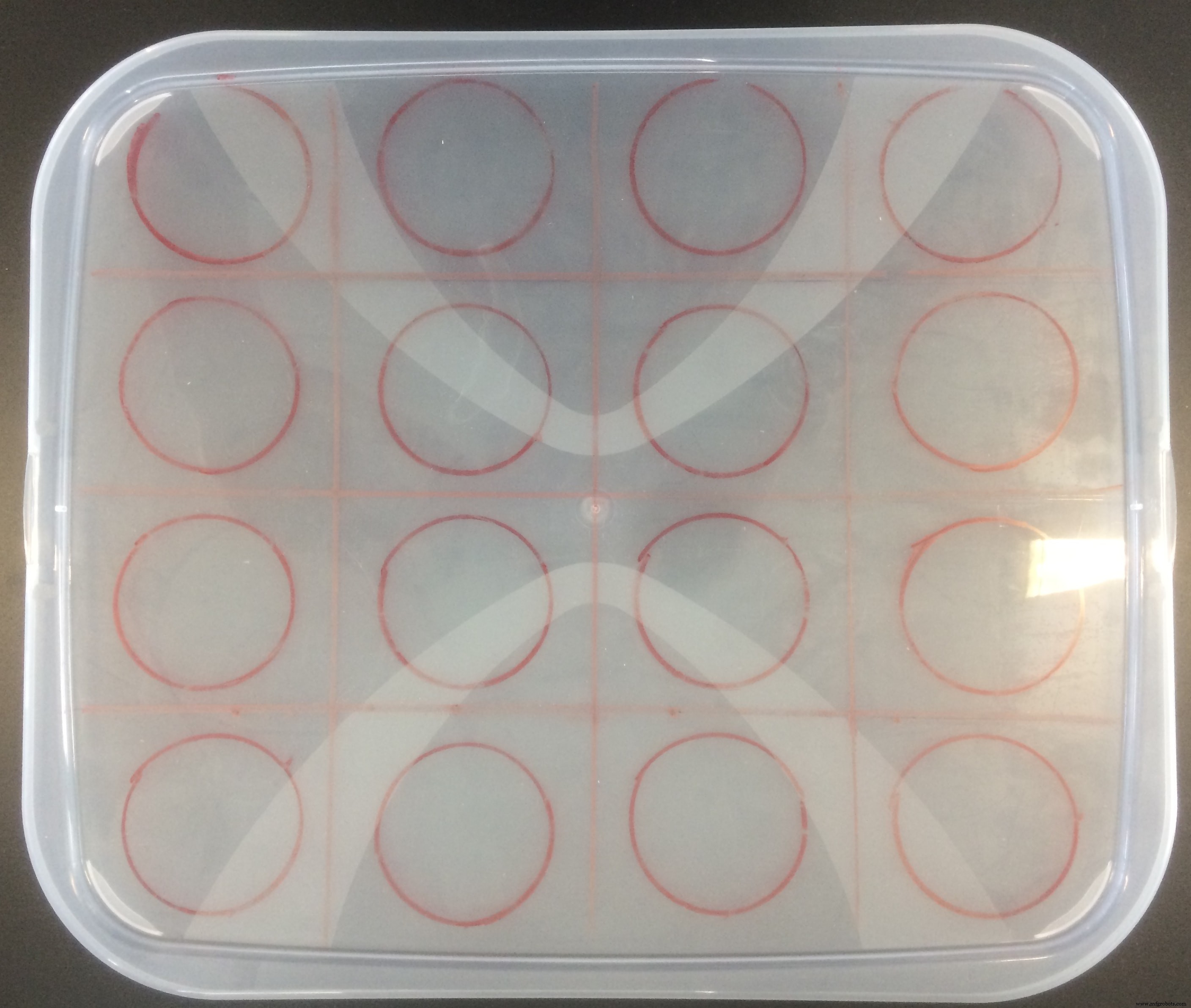
我还在当地一家商店买了一个我需要的近似尺寸的塑料容器,并画出了要钻孔的孔!
这是我组装的测试系统,里面有椰子颗粒、粘土球和土壤中的植物!
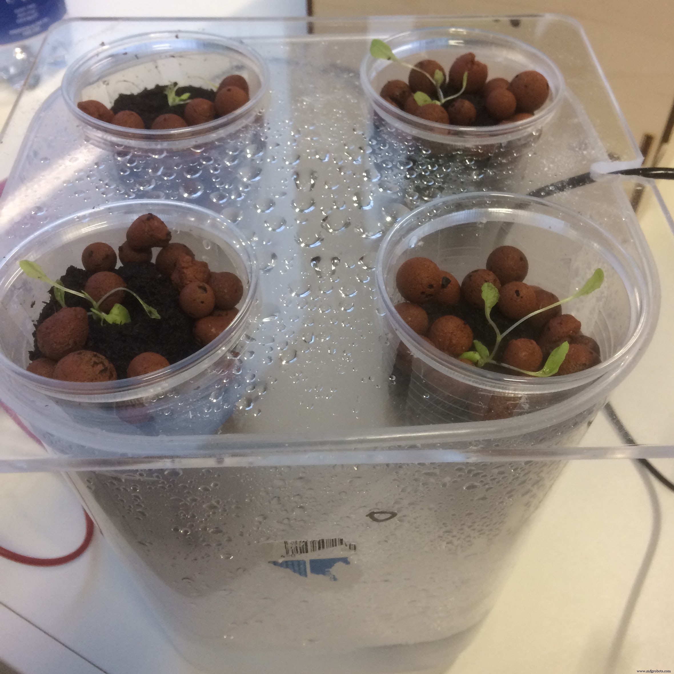
老实说,结果可能会更好:D
在我的雾系统中,只有少数植物存活下来。我的猜测是因为不断增长的介质!雾气不足以使粘土球保持湿润,土壤也不湿润。
复活节假期!
复活节假期期间我什么也没做,而且因为实验室关闭,所有系统也都关闭了。所以,我的植物都死了
怀着新的想法,我决定制作另一个系统,但这次使用的是基于先前观察的另一种生长介质
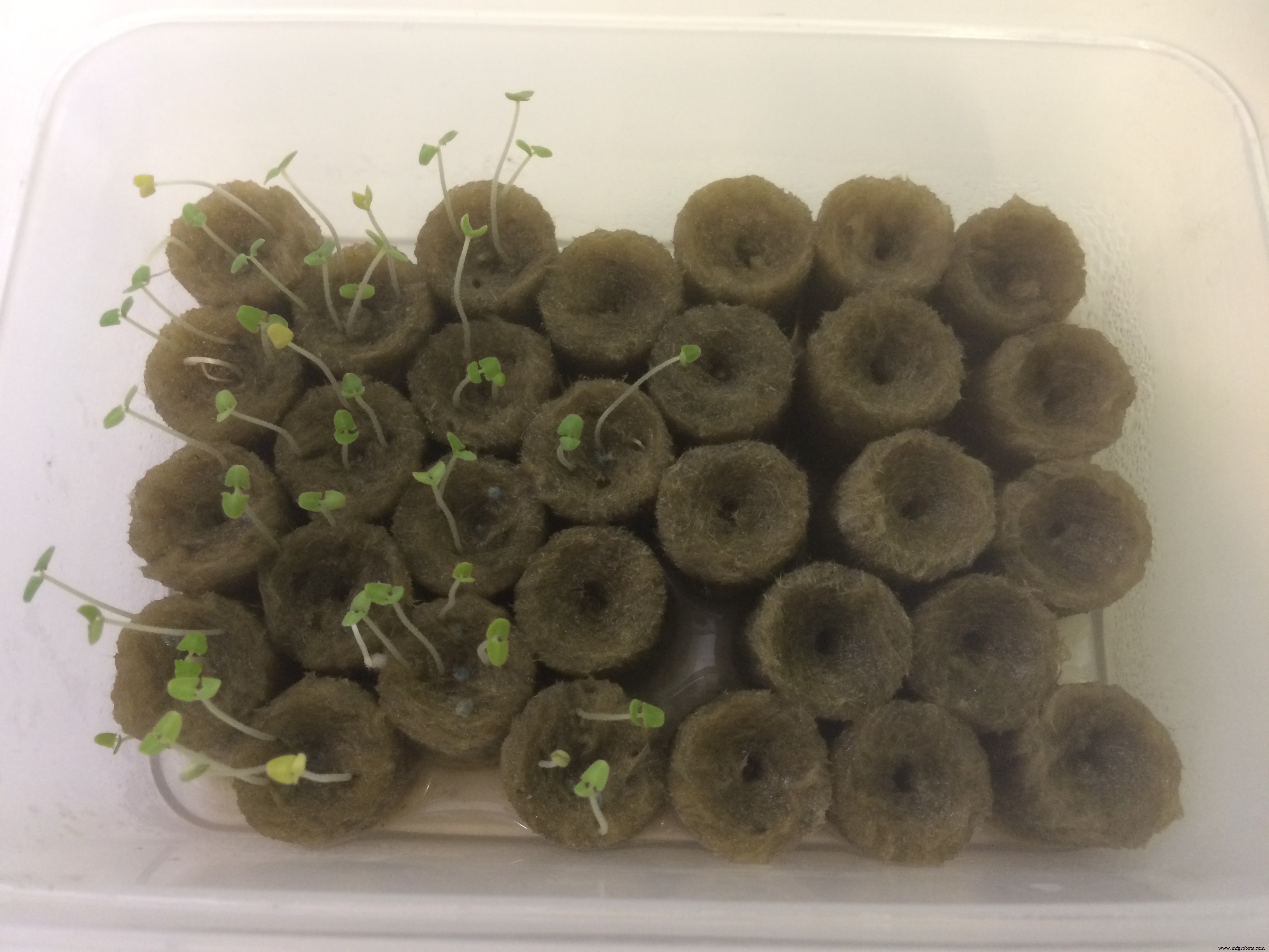
我为这个系统选择的生长介质是 Rock Wool .我在我们当地的宜家商店买的。我也从他们部门买了几颗种子

然后我将新种子放入岩棉中发芽一周!
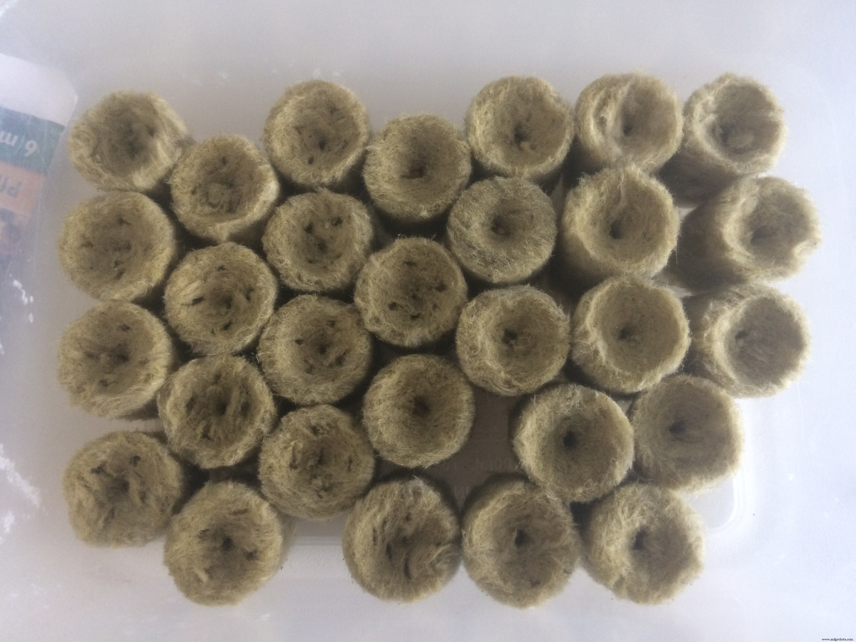
一周后,我检查了我的盒子,发现一种种子成功了,另一种失败了!由于时间不够,我继续发芽的种子
同时,我设置了另一个雾系统,并会尝试增加其工作时间,看看我是否可以使用雾发芽,ONLY FOG!
我会继续尝试不同的参数和设置,看看我能达到多远!)
电子设计与生产
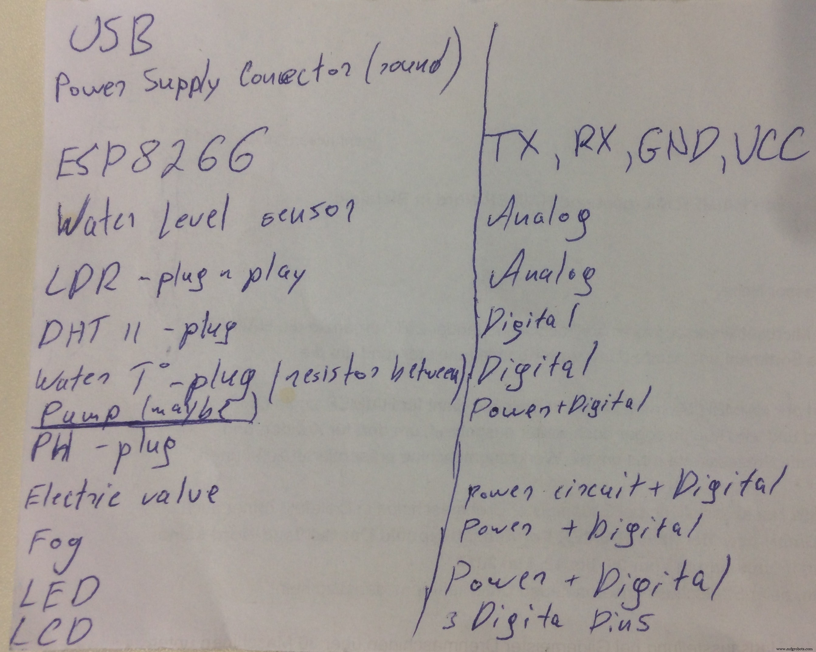
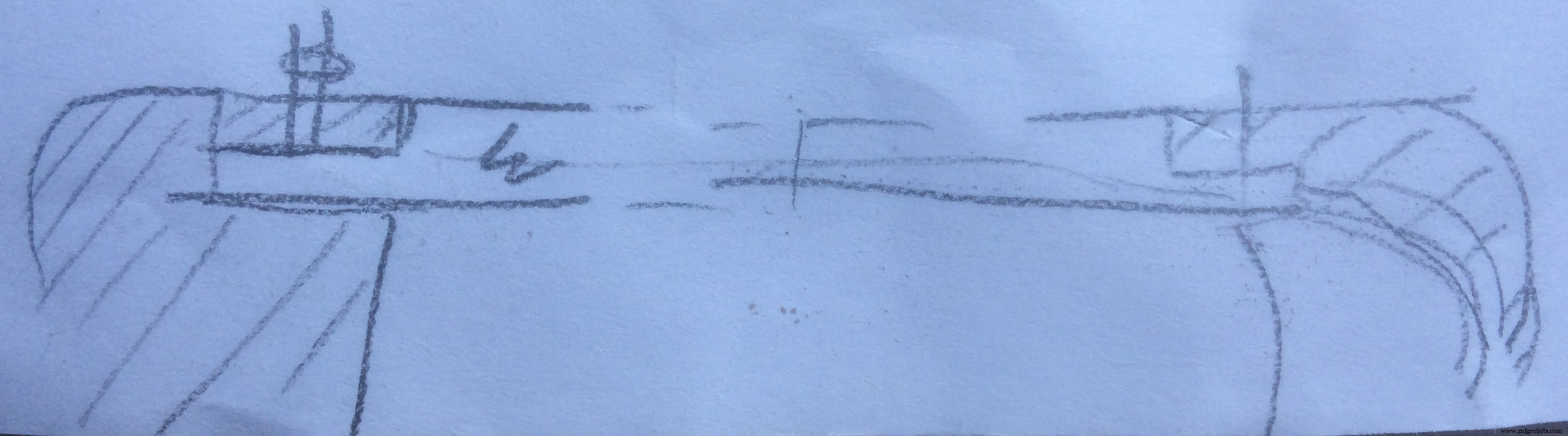
在开始设计最终电路板之前,我坐下来在一张纸上画出电路板必须实施和满足的所有功能和要求!我还会跟踪将要使用多少个引脚,以便更好地估计并决定哪个将成为最终的微处理器
这是应该在板上的草图:
在哪块板上使用的最终选择是 satshakit 来自 Daniele Ingrassia 和 FABLEO 作者:乔纳森·格林纳姆
satshakit 是 100% Arduino IDE 和库兼容的、可制造的和开源板,也是 Fabkit 的改进版本。
与 Fabkit 相比的主要改进和功能有:
- 16Mhz 而不是 8Mhz
- 晶体代替谐振器
- 成本更低(7-9 欧元 vs 13 欧元)
- 100% 兼容默认的 Arduino IDE(satshakit 被识别为 Arduino UNO)
- ADC6/7 已连接而不是 ADC6/7 未连接(satshakit 激光和 cnc)
- 更大的空间便于焊接(satshakit 激光和 cnc)
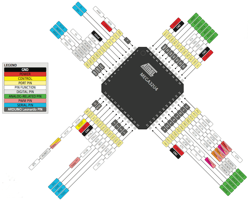
另一方面,FabLeo 具有非常相似的功能,加上硬件 USB!因为之前已经用过ATmega328p,所以想尝试一些新的东西,决定以FabLeo的设计为起点
我的圣经 此分配的 #1 指南是 ATmega32u4 引出线
为了设计电路板,我将使用的软件是 EAGLE (易于应用的图形布局编辑器)是一个灵活且可扩展的 EDA 原理图捕获、PCB 布局、自动布线器和 CAM 程序。 EAGLE 因其免费软件许可证和网络上丰富的组件库而受到爱好者的欢迎。
Eagle 有两个同时用于设计电路板的窗口:
- 原理图 (.sch) - 逻辑组件
- 电路板布局 (.brd) 对于我们铣削的实际板
安装 EAGLE 后,我想做的第一件事是创建新原理图 .电子学中的原理图是表示电路的图。它使用符号来表示真实世界的电子元件。最基本的符号是一个简单的导体(迹线),简单地显示为一条线。如果导线在图中连接,则它们在交叉点处显示为一个点。
为了将我的组件放置在原理图上,我必须下载并使用特殊的库 . Eagle 有很多我们可以使用的内置组件库。 fab 网络还维护了一个不断更新的库:
fab.lbr
为了安装库,在 EAGLE 环境中,转到顶部工具栏并选择 Library 菜单。然后选择use 并打开 .lbr 我刚刚下载的文件。
现在我可以去添加组件 并选择库,我选择要放置的组件。
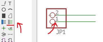
当我将所有组件都放在我的原理图上时,我必须将它们中的每一个都连接到微处理器的引脚上。在 EAGLE 左侧菜单中,单击 Net , 命令允许我绘制绿线并连接引脚。重要的是从引脚上的小线开始连接(我在图片上标记了它)
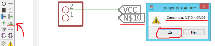
为了避免多个连接,我将使用标签。 .在 EAGLE 左侧菜单中,我按 Add Label 并将其添加到我的连接线的末尾。如果我按右键单击 然后选择name ,我可以将标签与我用于微处理器引脚的名称相同,并以这种方式连接!
如果我做的一切都正确,应该会出现一条消息,指出:您确定要将标签 (N$10) 与 GND 连接吗?
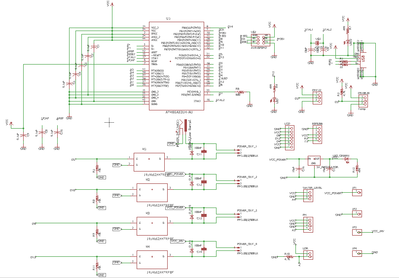
在这个阶段,在化学中,重要的是逻辑 所有的连接,而不是它看起来的样子。我把所有的组件都放好后,按照逻辑连接起来,就是这个样子:
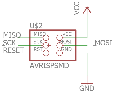
我添加了 AVRISP 针头,并按照连接器的顺序放置它们。这些引脚将用于对我的电路板进行编程。
这是USB的原理图 电路和晶体一起
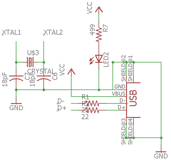
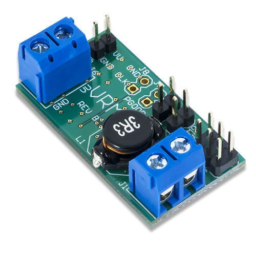
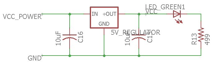
我还添加了一个电压调节器 电路将输入12V转换成5V为整板供电
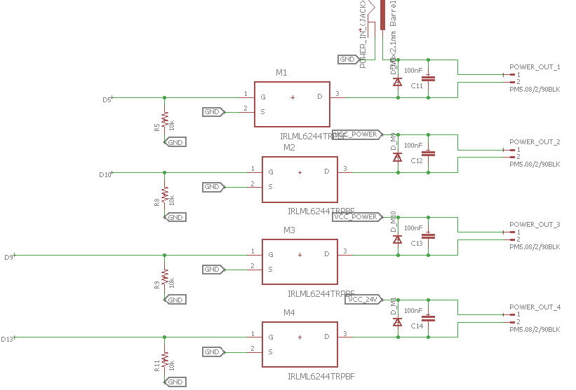
该板的重要特性之一是 MOSFET 电路,我添加了其中的4个,3个直接连接到输入(12V),一个将连接到升压稳压器。最后一个将用于为24V工作的雾供电
仔细检查所有连接后,我可以继续下一步,即电路板布局 .在顶部菜单上,我按 Generate/Switch to Board .
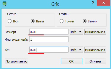
我做的第一件事是增加 Grid 解决。我去查看 菜单,然后按 Grid , 并将值更改为 0.01 .这将使我在绘制路线时更加精确。
令人惊讶的是,我迄今为止制作的最复杂的电路板的布线也是最快的!)我为自己感到自豪。做板子的经验对提高速度有很好的影响。完成路由后,这就是小野兽的样子:
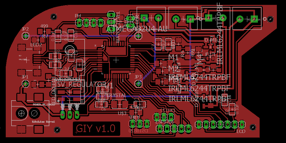
对于这个板,我也使用了我之前学到的技巧。我在组件周围绘制一个多边形,然后按右键单击 在多边形线上,我将名称更改为 GND。这将填充多边形内的整个区域,并使其成为 GND。
这将节省大量的时间、空间和精力
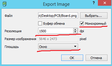
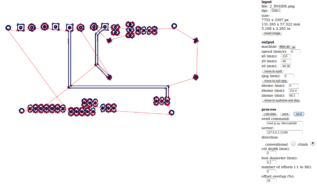
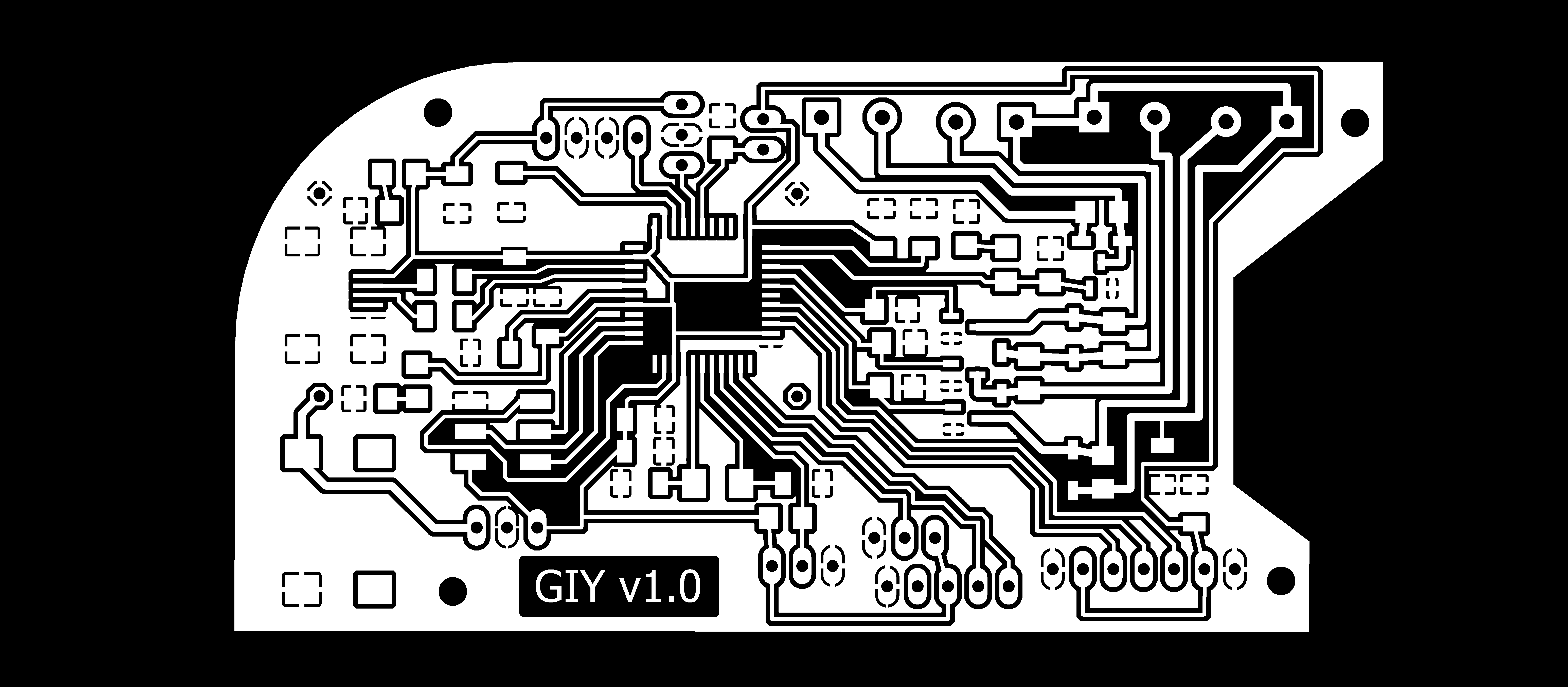
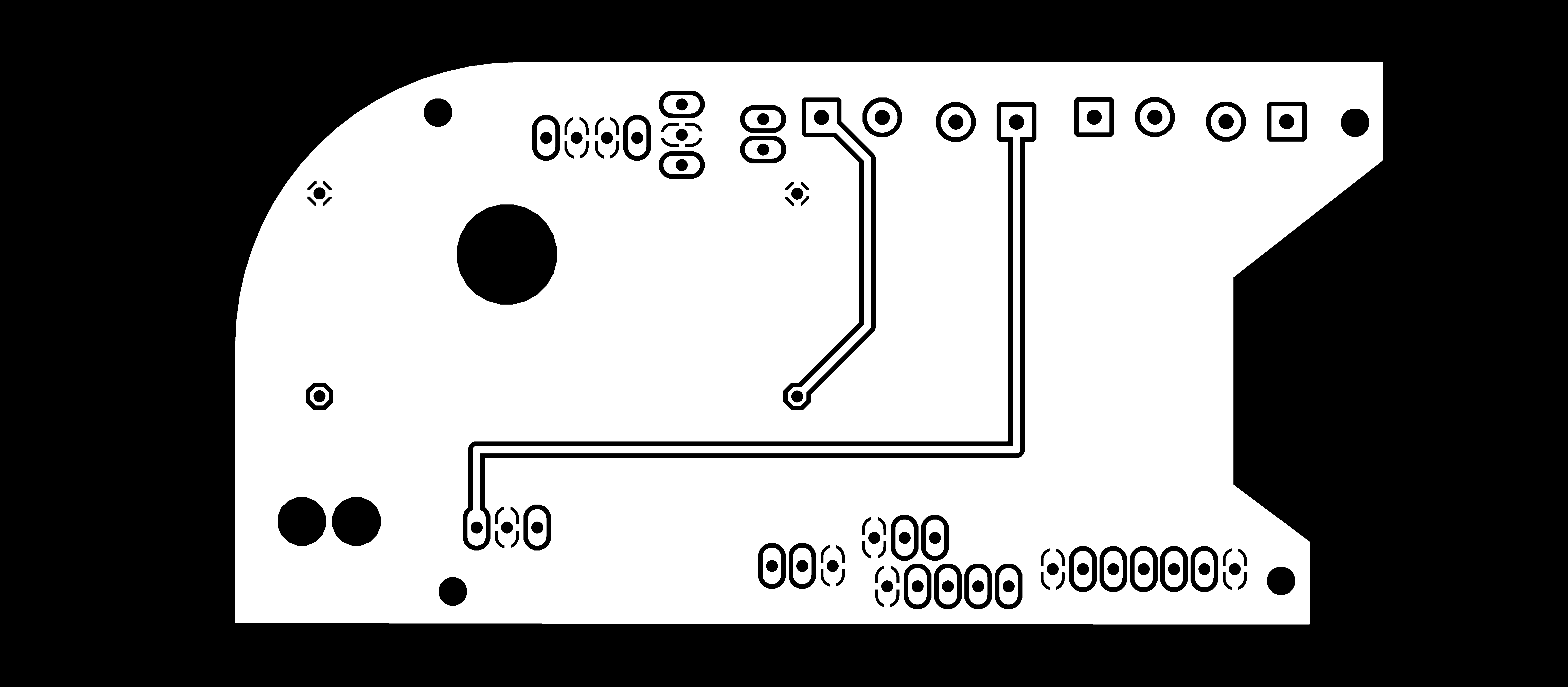
当我仔细检查所有内容时,我可以导出 我的文件为 .png 图片。
在出现的窗口中,我将分辨率提高到 1500 dpi , 点击 monochrome , 然后选择 window 模式。
要编辑 .png 图像,我将使用在 GIMP 中打开我的图像 ,并使用矩形选择工具 ,我选择的图像从四面八方留出一些空间。在我按下 File 之后 和复制 所选区域。要继续处理所选图片,我再次单击 File , 和 从剪贴板创建
这是我在所有编辑后得到的:
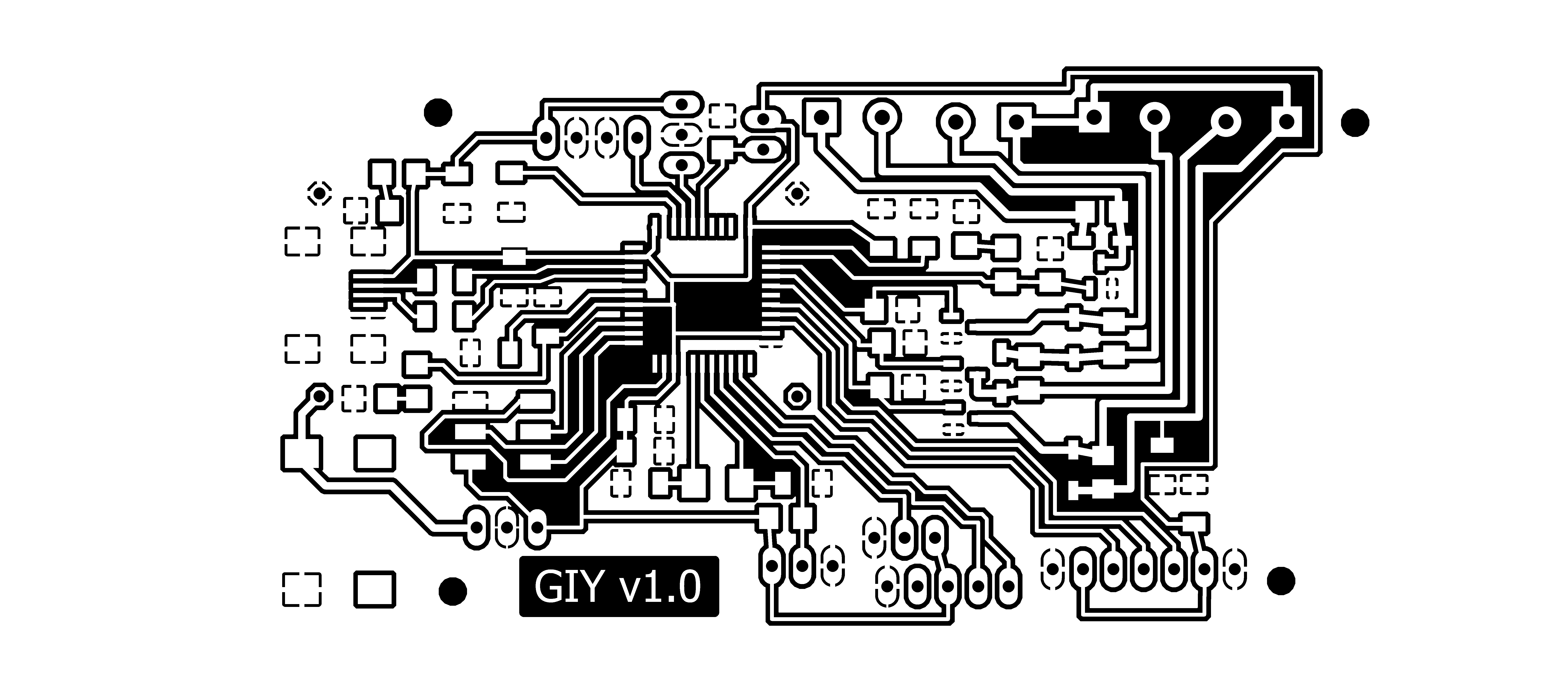
此图像已准备好打印,我将其称为 Inside_Cut
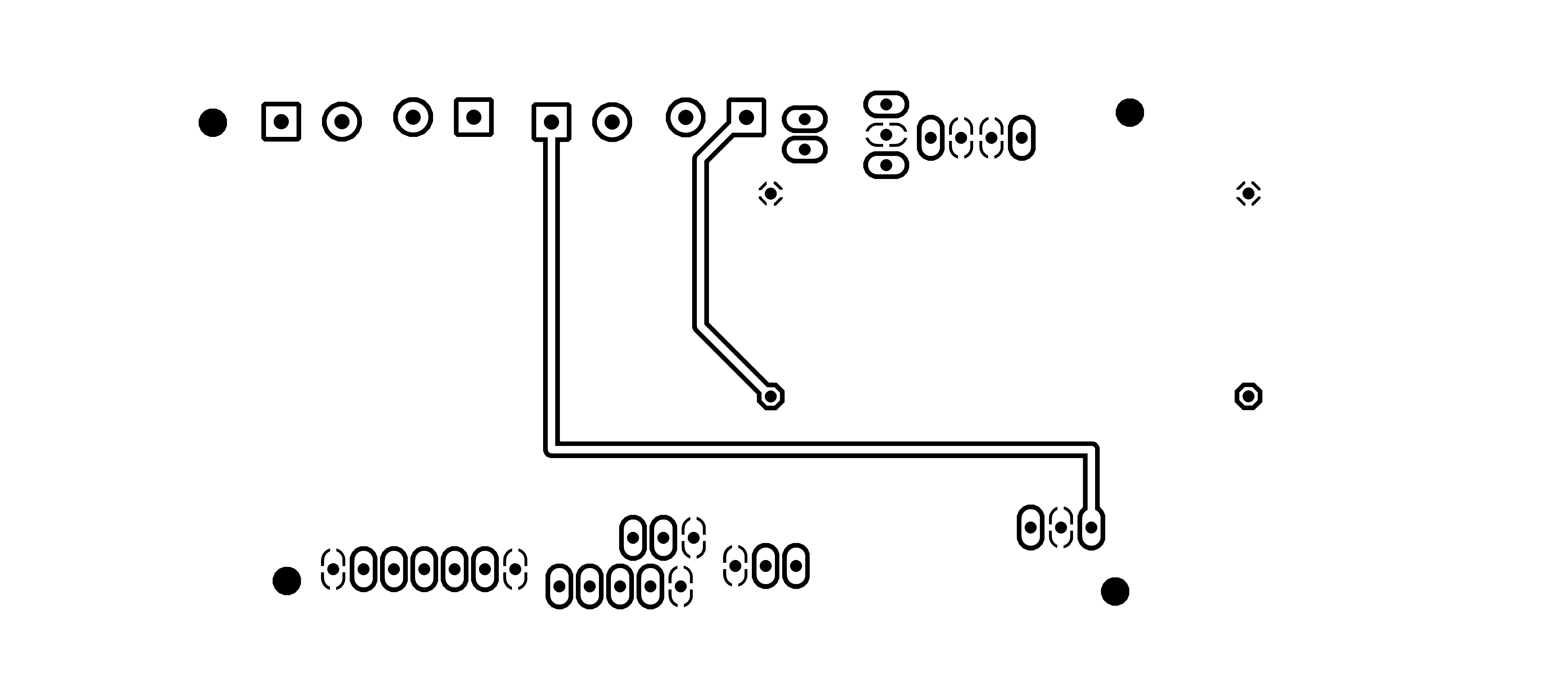
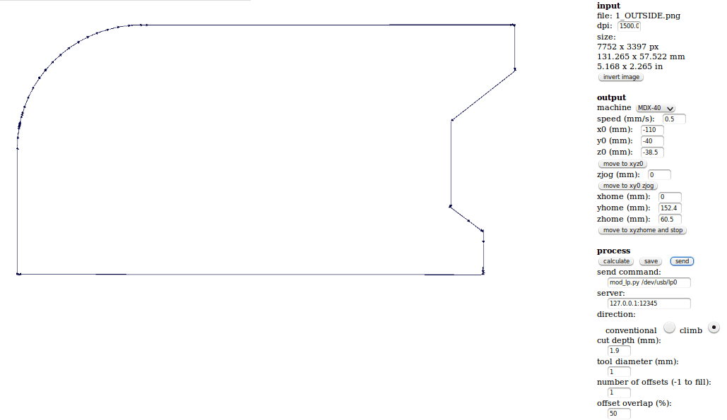
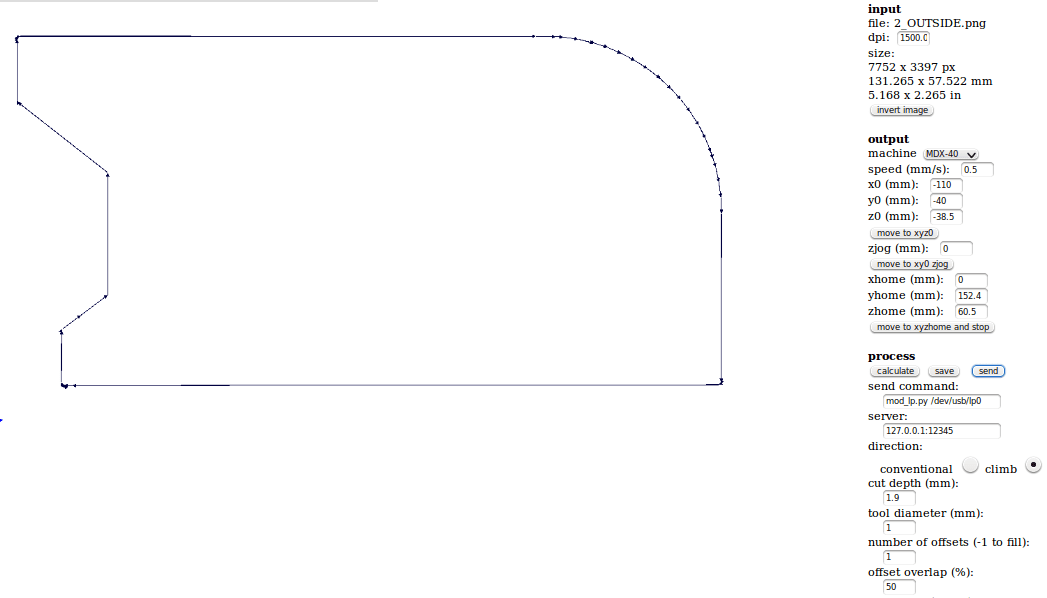
我为外切准备流程 ,这就是我得到的:

因为我的板子是双面的,我得磨两块,然后把它们粘在一起。唯一要记住的是底部必须水平镜像
底部 Inside_Cut

底部Outside_Cut
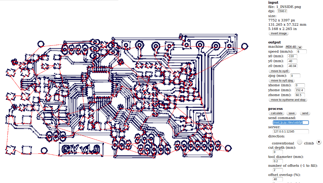
现在我可以继续使用数控铣床了。所以,我再次使用了 FabModules 将 .PNG 文件转换为 Gcodes 对于罗兰机器。
让我们开始使用 Fab 模块。当我在浏览器窗口中引入ip地址时,第一个出现的界面是:

在我按下灰色按钮后输入格式 ,应该会出现一个新菜单,其中包含加载 .PNG 图像的选项。这里我上传第一张图片,也就是里面的雕刻。完成后,Fab Modules 中会出现图像的预览,也会显示其他字段和其他参数
在窗口的右侧,我们有许多输入参数。为了能够移动机器,我们必须输入以下参数:
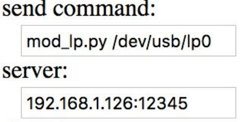
mod_lp.py /dev/usb/lp0 进入发送命令 字段
hostname_of_your_machine 进入服务器 字段(只是没有http或/的地址)
为了移动机器,我只需在相应的字段中输入 x、y 和 z 位置坐标。在移动机器之前,我必须确保 zjog 参数始终设置为 0,即使它会自动更改。要移动机器,我必须按 move to xyz0 按钮。
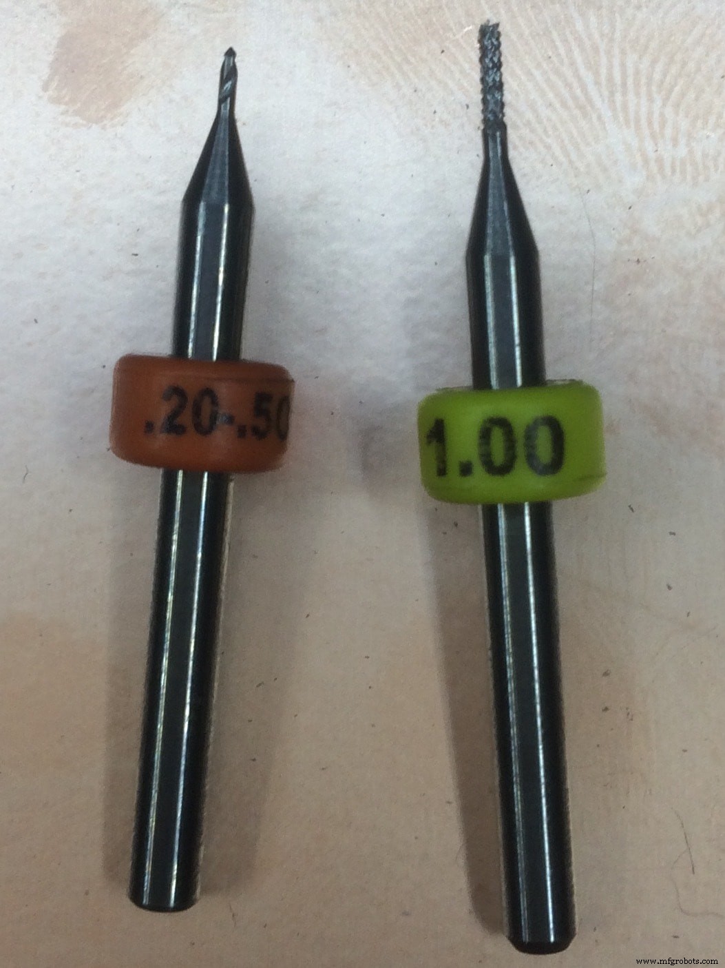
* 一个小生活小窍门 是用万用表检查工具和表面是否有连接。作为雕刻 PCB 的工具,建议使用 0.2 mm 的直径 及以下,切割时我们可以使用 1 mm 工具。
所以我的最终设置是这样的:
对于外切,设置保持不变,除了 Z 轴的值,因为我用 1mm 工具替换了 0.2mm 工具。这是它的样子:
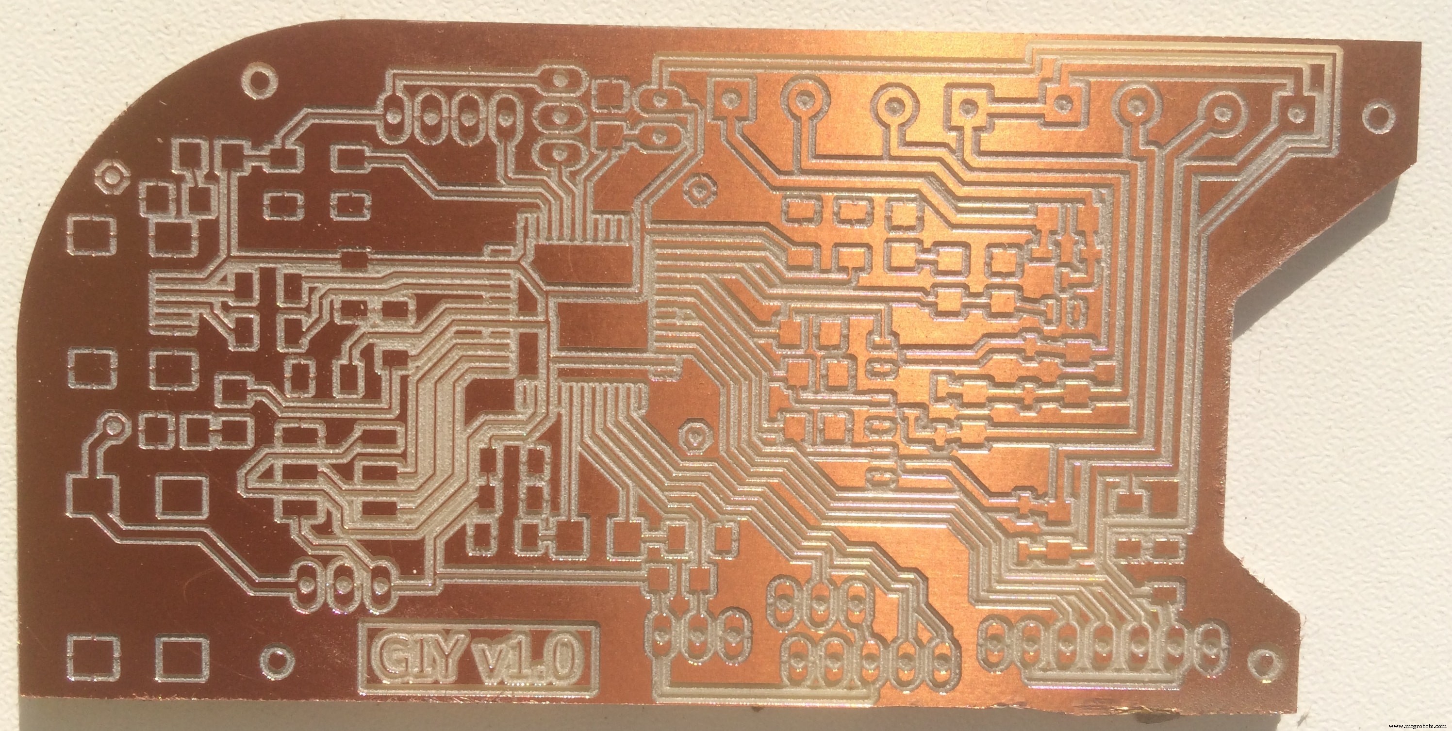
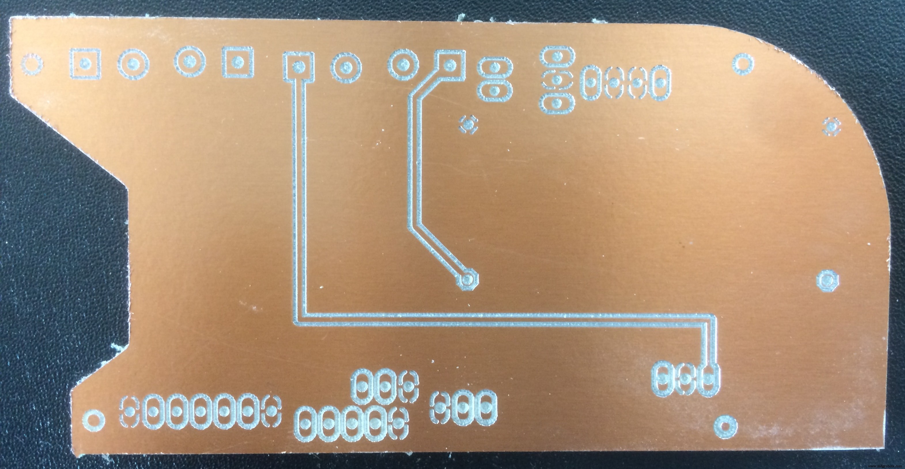
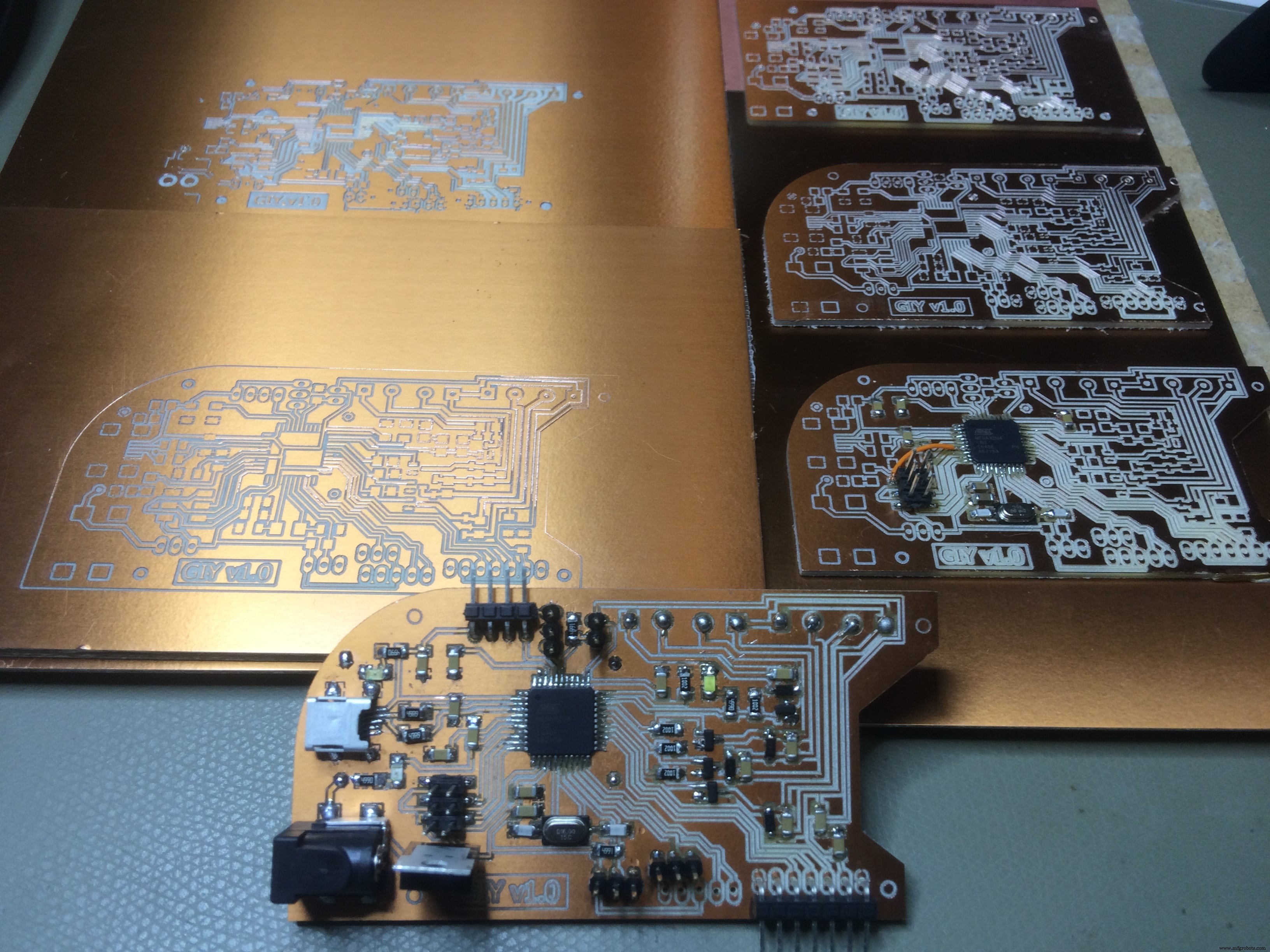
对底部重复相同的过程 并铣削内部和外部零件:
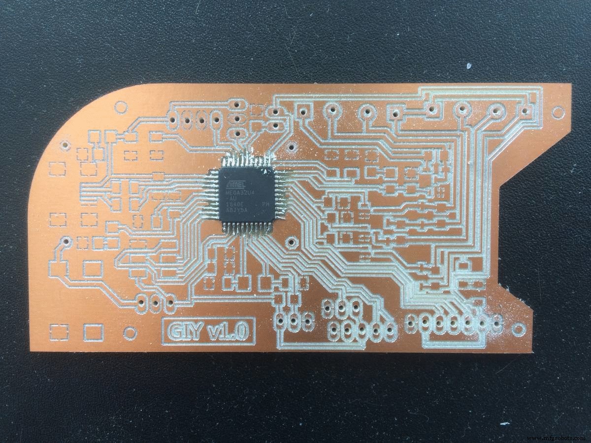
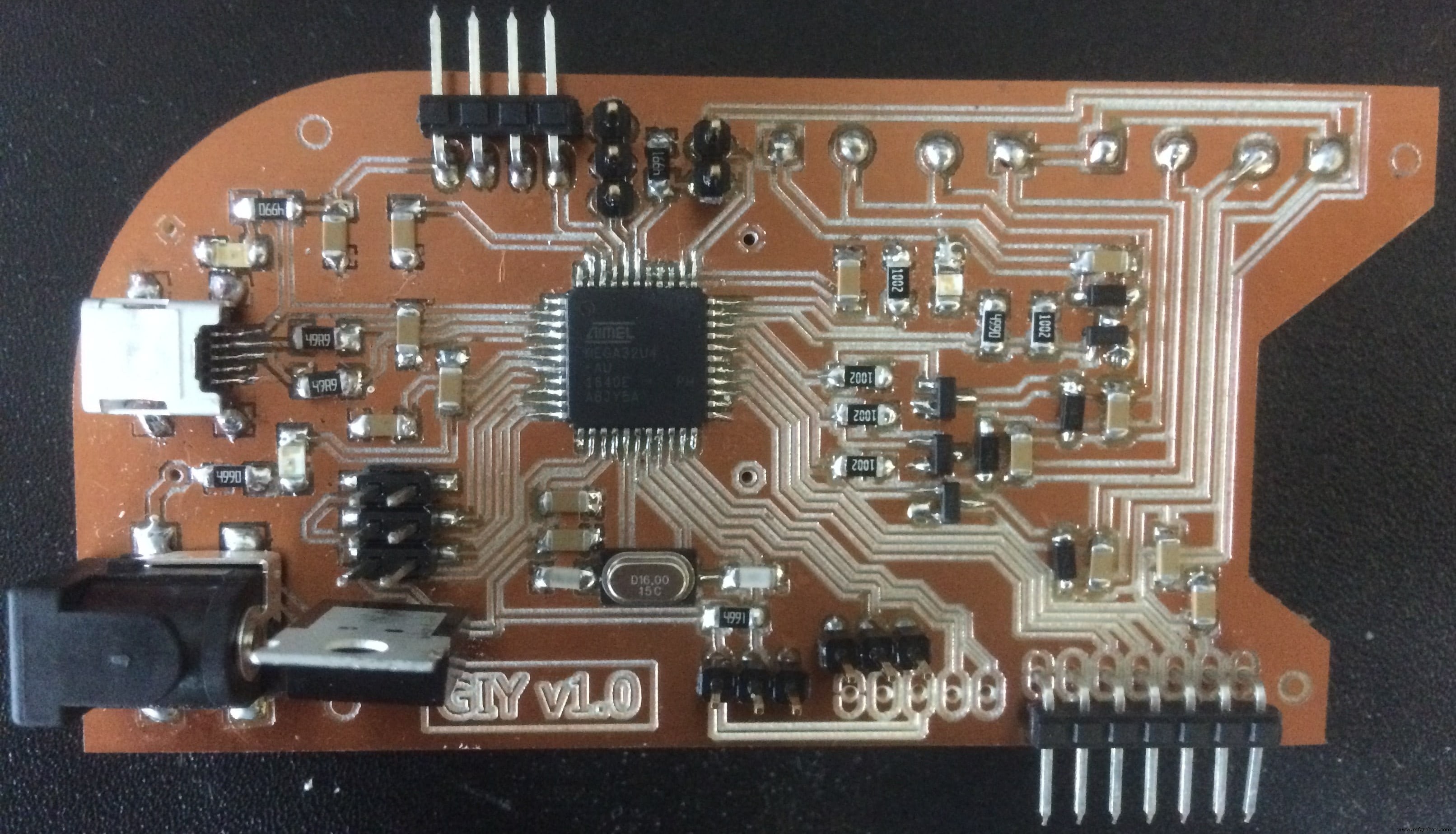
这是Top的最终结果 部分:
而底部 部分:
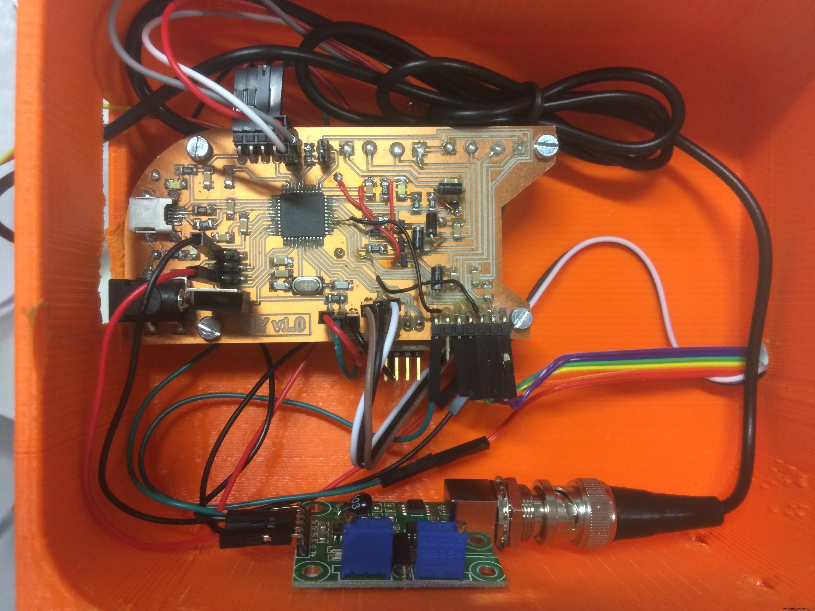
现在让我们焊接这个!
In order to make sure that I soldered everything in a right way, after each component soldered, I used the multimeter to check if there is conductivity between the component and the traces.
Short animation of the process:
When I plugged in the PCB board to check if everything is fine, I noticed an error. From experience, I know that the error was from a short circuit, because the computer was disconecting the Arduino all the time I connect the VCC and GND to it. So my guess was that somewhere on the board VCC and GND are connected, and using the multimeter, I confirmed that I was right.
It was late, and I got so f*ckin' mad because of that, took me one hour under the microscope to find that little mistake. Here it is:
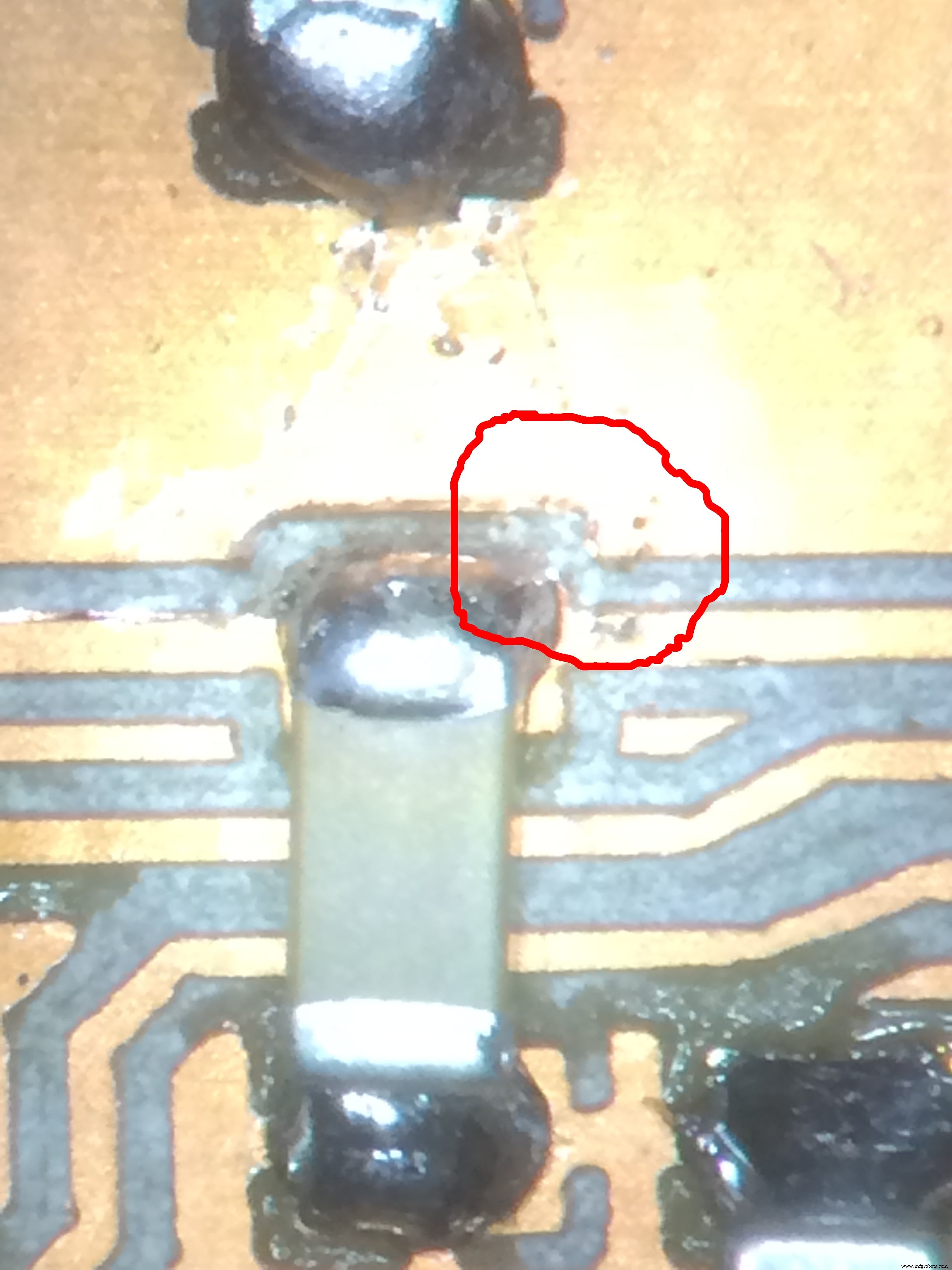
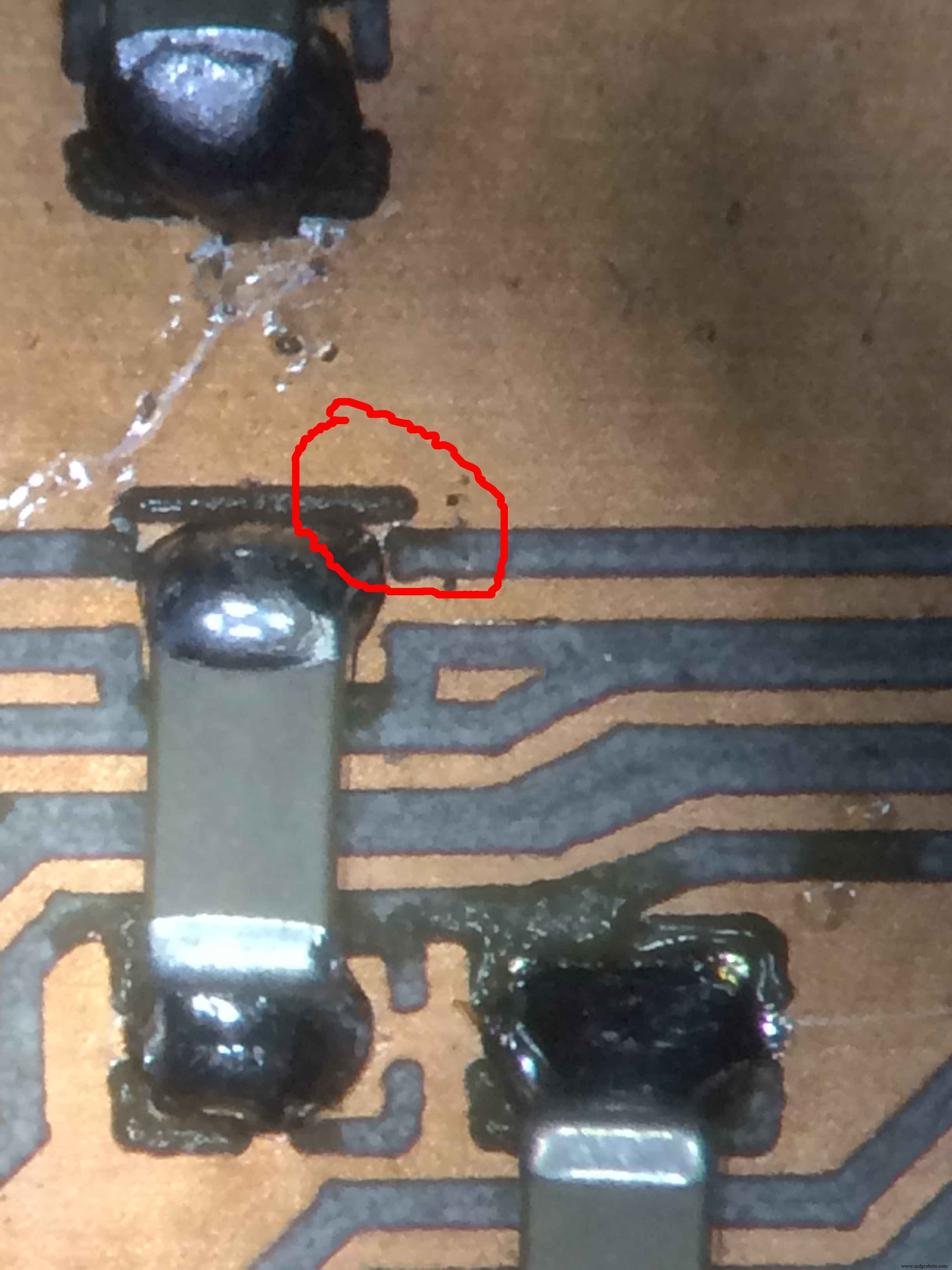
I fixed it by scratching with a knife, and increasing the isolation!
Another thing is placing the Step Up Voltage Reguator on the back side of my board.
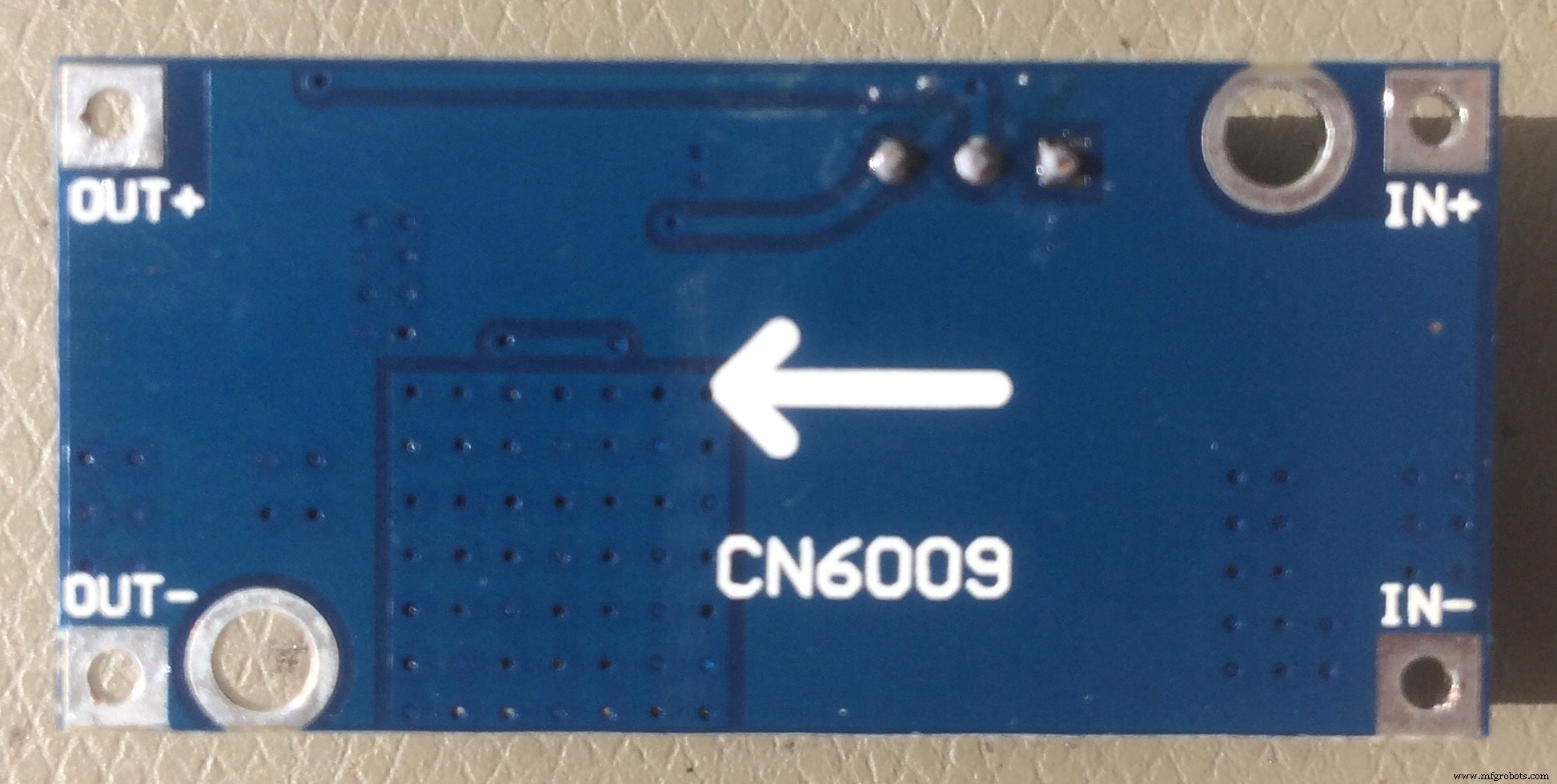
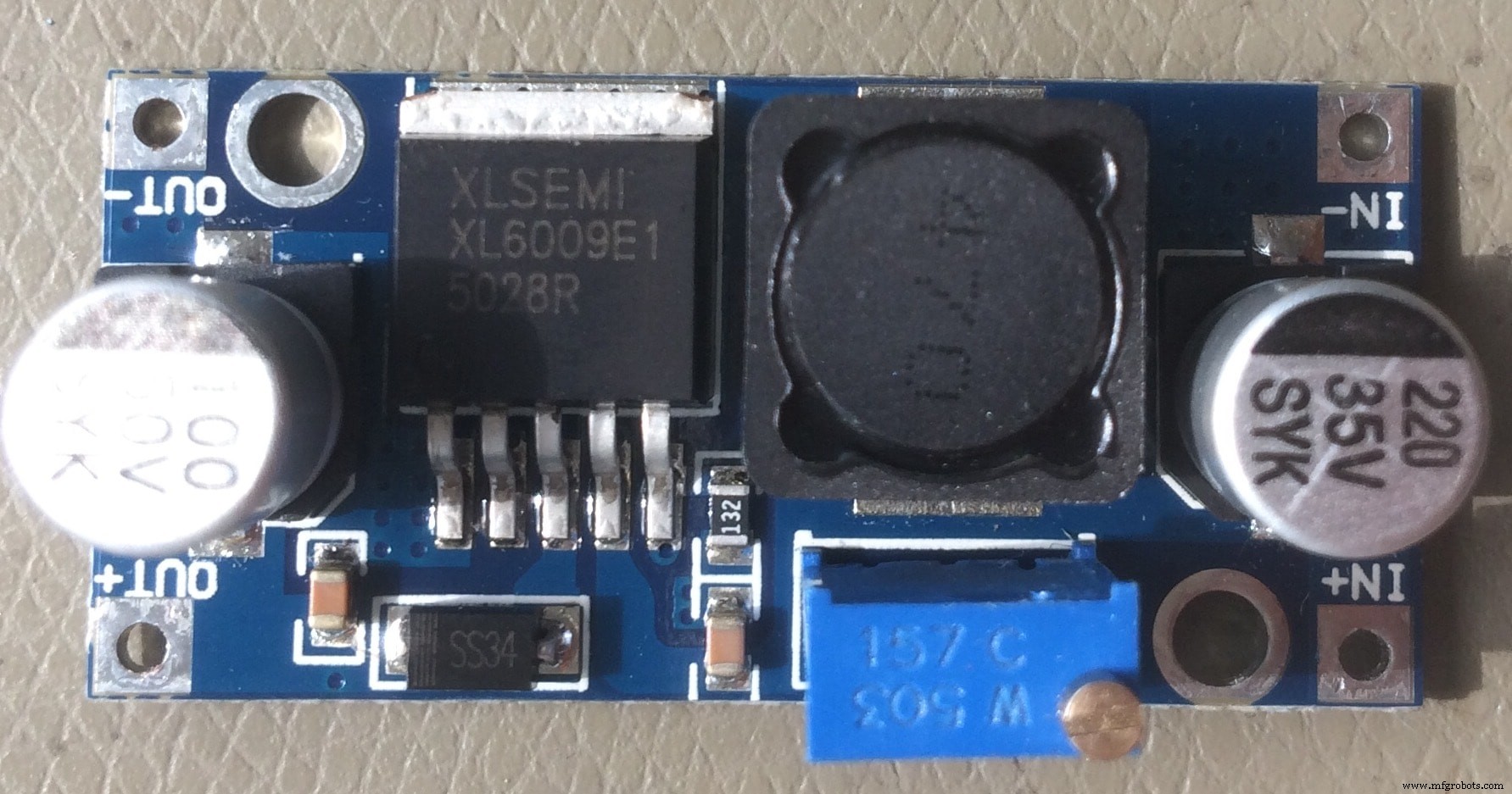
I measured the dimensions in advance, and designed predrilled holes to fix it with the pinheaders. But before soldering it on the back side, I have to calibrate it.
The idea is that when I power the board with 12V, the step up will output 24V necessary for the Ultrasonic Atomizer, which is connected to the MOSFET circuit
I used the bench power supply, with a fixed 12V, to measure the output voltage using a multimeter.
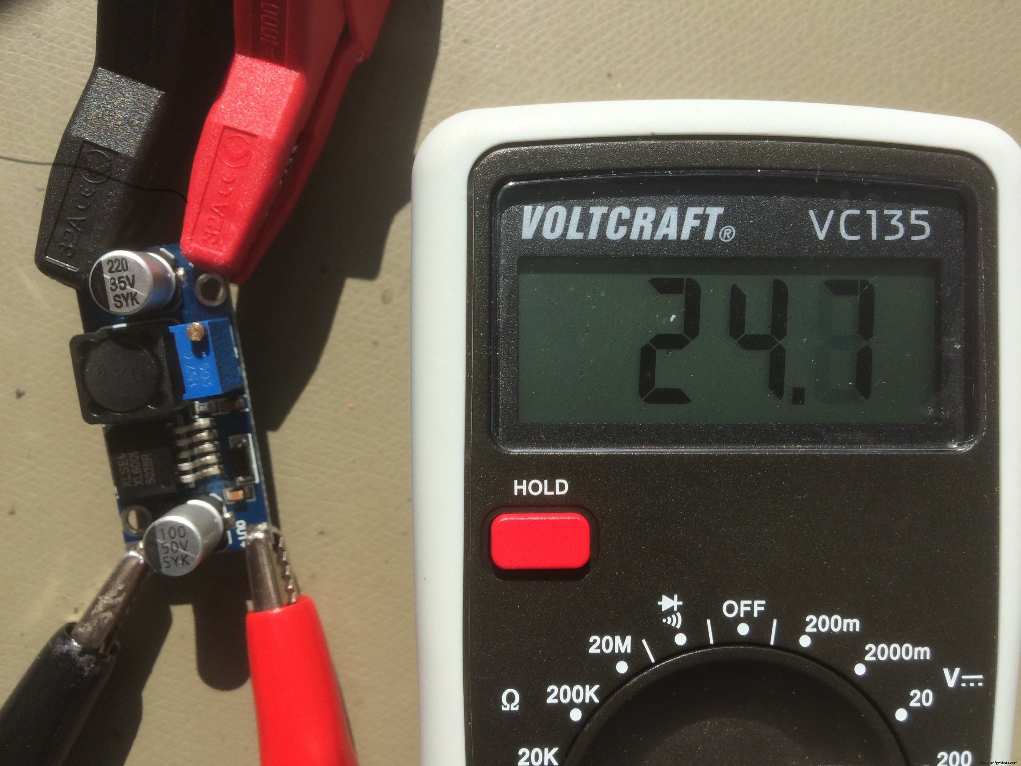
After I adjust the output to the one that I need, 24V in my case, I can solder it to the back side of my board!
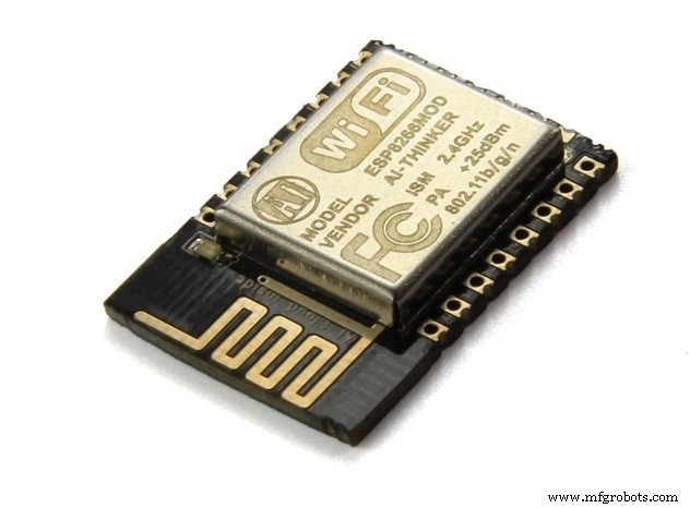
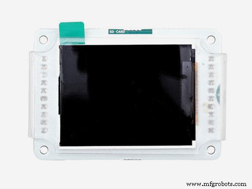
Also on the back side, I placed the WiFi board which I made during the Networking and Communications week!
So, here is The BEAST :
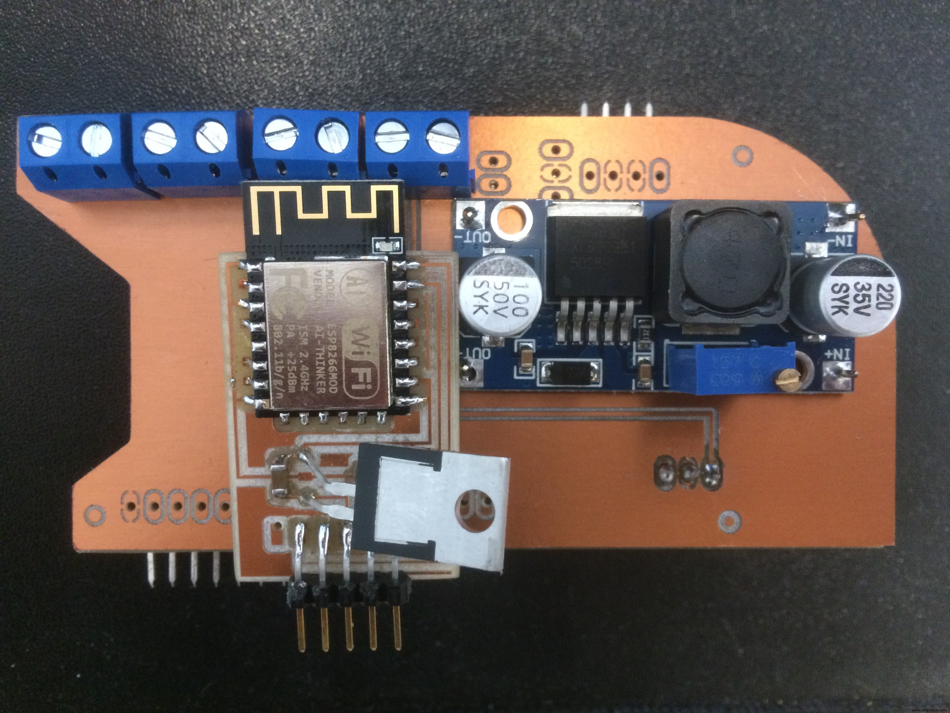
A HERO picture for those who may think that it was easy, and everything went smooth :D
Download Files:
GIY Schematics (.sch)
GIY Layout (.brd)
Board#1 Internal Cut(.png)
Board#1 External Cut (.png)
Board#2 Internal Cut (.png)
Board#2 External Cut (.png)
Wiring &Embedded programming (I/O Devices)
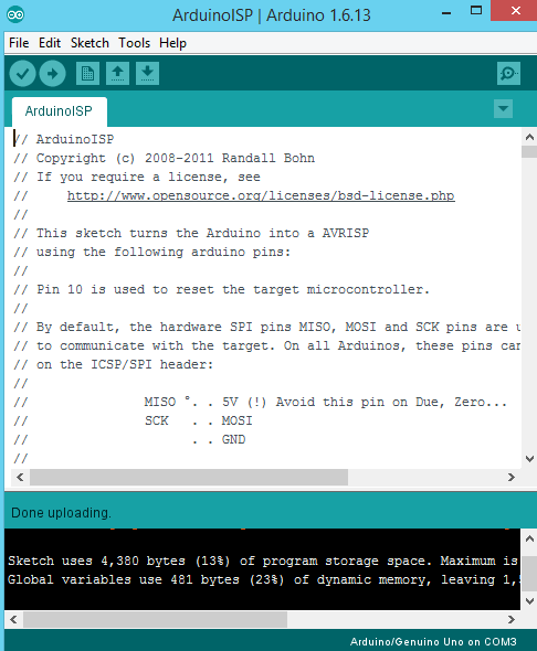
To program my board I used Arduino IDE . I connect the arduino board to the USB hub, in the tools menu select the right board (Arduino Leonardo) and the port, after go to File --> examples and open the Arduino as ISP 草图。 Upload the code.
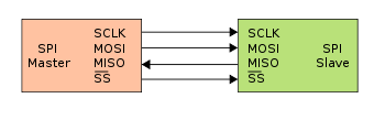
After I see done uploading, which means that the code is uploaded to the board, I disconnect the arduino from the PC. The next step is to connect my PCB board to Arduino using some wires. The connection scheme is this one:
- SCLK:Serial Clock (output from master) ----------> Arduino Pin 13
- MOSI:Master Output Slave Input ----------> Arduino Pin 11
- MISO:Master Input Slave Output ----------> Arduino Pin 12
- VCC:Positive supply voltage ----------> Arduino VCC
- GND:Ground ----------> Arduino GND
- RST:----------> Arduino Pin 10
I connect the arduino board to the USB hub. Under Tools select the right board, select Arduino as ISP programmer, double check the parameters, and press the Burn Bootloader 按钮。
And I see Done Uploading! Good sign)
To test the board, I upload the basic Blink example code:
Ohh, I LOVE that BLINK :D Now let's go to sensors!
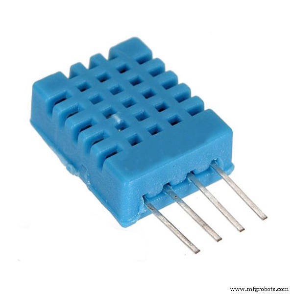
First sensor that I want to use is DHT11 - Temperature &Humidity Sensor
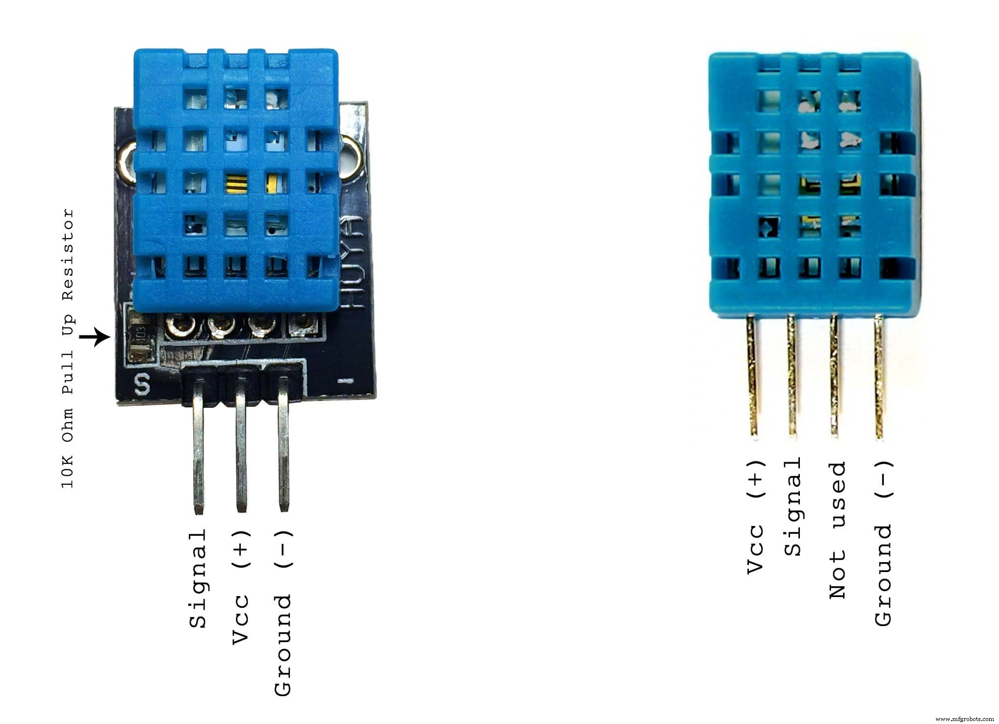
These sensors are very basic and slow, but are great for hobbyists who want to do some basic data logging. The DHT sensors are made of two parts, a capacitive humidity sensor and a thermistor. There is also a very basic chip inside that does some analog to digital conversion and spits out a digital signal with the temperature and humidity. The digital signal is fairly easy to read using any microcontroller.
Some characteristics:
- Ultra low cost
- 3 to 5V power and I/O
- 2.5mA max current use during conversion (while requesting data)
- Good for 20-80% humidity readings with 5% accuracy
- Good for 0-50°C temperature readings ±2°C accuracy
- No more than 1 Hz sampling rate (once every second)
- Body size 15.5mm x 12mm x 5.5mm
- 4 pins with 0.1" spacing
The wiring is pretty easy, just VCC, GND, and any Digital Pin! In my case, I designed in advance the connection for this sensor.
To test it, I will upload a simple sketch. The sketch includes the library DHT.h
So here is the code:
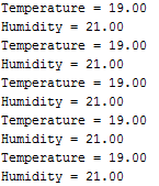
// DHT11 Temperature and Humidity Sensors Example#include "DHT.h" //include DHT library#define DHTPIN 2 //define as DHTPIN the Pin 2 used to connect the Sensor#define DHTTYPE DHT11 //define the sensor used(DHT11)DHT dht(DHTPIN, DHTTYPE); //create an instance of DHTvoid setup() { Serial.begin(9600); //initialize the Serial communication dht.begin(); //initialize the Serial communication}void loop() { float h =dht.readHumidity(); // reading Humidity float t =dht.readTemperature(); // read Temperature as Celsius (the default) Serial.print("Temperature ="); Serial.println(t, 2); //print the temperature Serial.print("Humidity =");; Serial.println(h, 2); //print the humidity delay(2000); //wait 2 seconds } When I open the Serial Monitor, this is what I get:
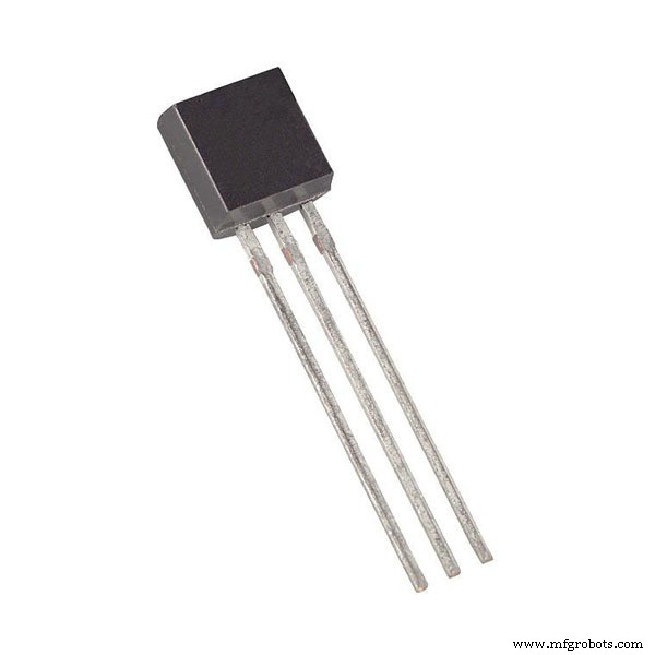
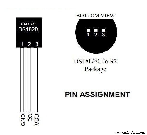
Another sensor which I want to use is DS18B20 - One Wire Digital Temperature Sensor
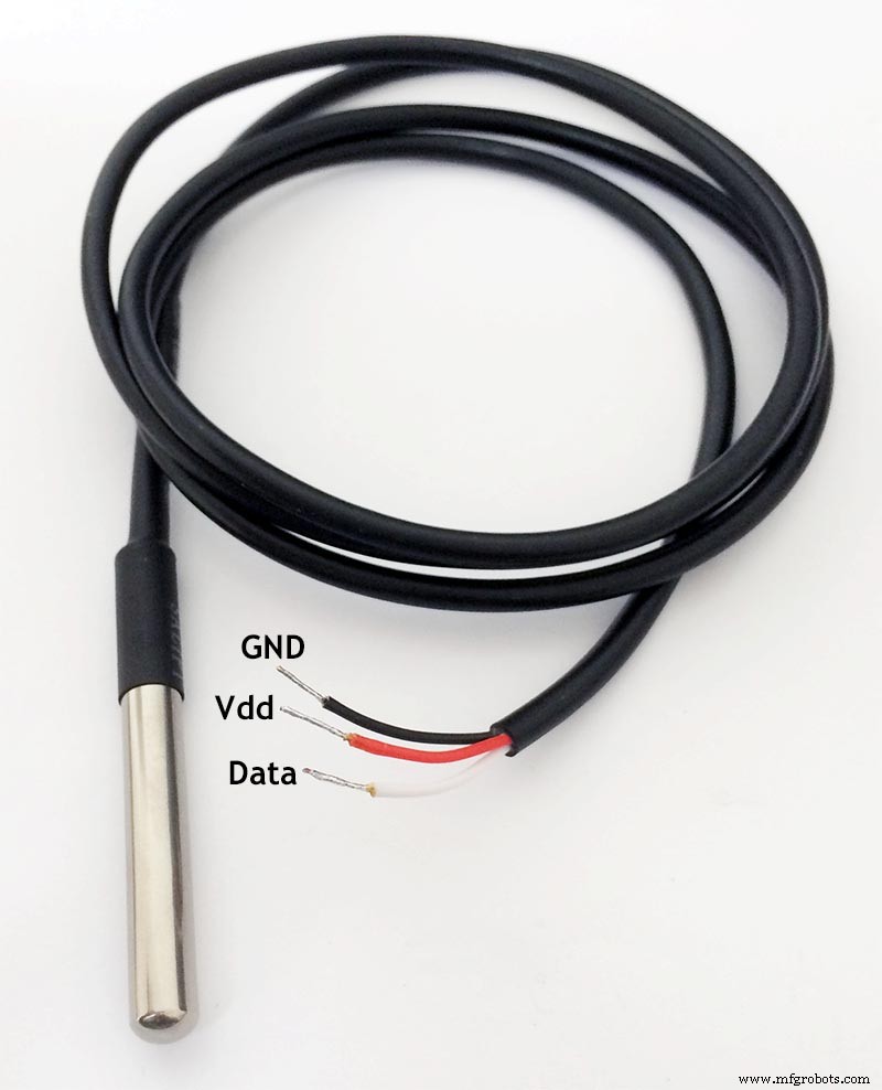
DS18B20 is 1-Wire digital temperature sensor from Maxim IC. Reports degrees in Celsius with 9 to 12-bit precision, from -55 to 125 (+/-0.5). Each sensor has a unique 64-Bit Serial number etched into it - allows for a huge number of sensors to be used on one data bus.
This is by far one of the most simple digital sensors to hookup. Aside from power and ground, it has a single digital signal pin that I will be connecting to digital pin which I designed in advance. It also requires a 4.7k pull-up resistor between the signal and power pin, which unfortunately I forgot to place on my PCB. That is why, I will solder it manually directly to the sensor cables.
Before I start, I have to download the libraries:OneWire.h and DallasTemperature.h
Upload the following sketch:
// First we include the libraries#include #include #define ONE_WIRE_BUS 3 // Setup a oneWire instance to communicate with any OneWire devices, (not just Maxim/Dallas temperature ICs) OneWire oneWire(ONE_WIRE_BUS); // Pass our oneWire reference to Dallas Temperature. DallasTemperature sensors(&oneWire);void setup(void) { // start serial port Serial.begin(9600); sensors.begin(); } void loop(void) { // call sensors.requestTemperatures() to issue a global temperature (request to all devices on the bus)sensors.requestTemperatures(); // Send the command to get temperature readings Serial.print("Temperature is:"); Serial.print(sensors.getTempCByIndex(0)); //You can have more than one DS18B20 on the same bus. 0 refers to the first IC on the wire delay(1000); } The funny thing is that after I successfully programmed the sensor, It stopped working while I was integrating all the sensors together! I spend quite a long time trying to figure out why it does not work, but due to the limited time, I decided to use another DS18B20 sensor which was available in our FabLab stock, and waterproof it by myself!
So I took the sensor, and used the datasheet to properly solder the cables, and isolate them from each other using shrink tubes
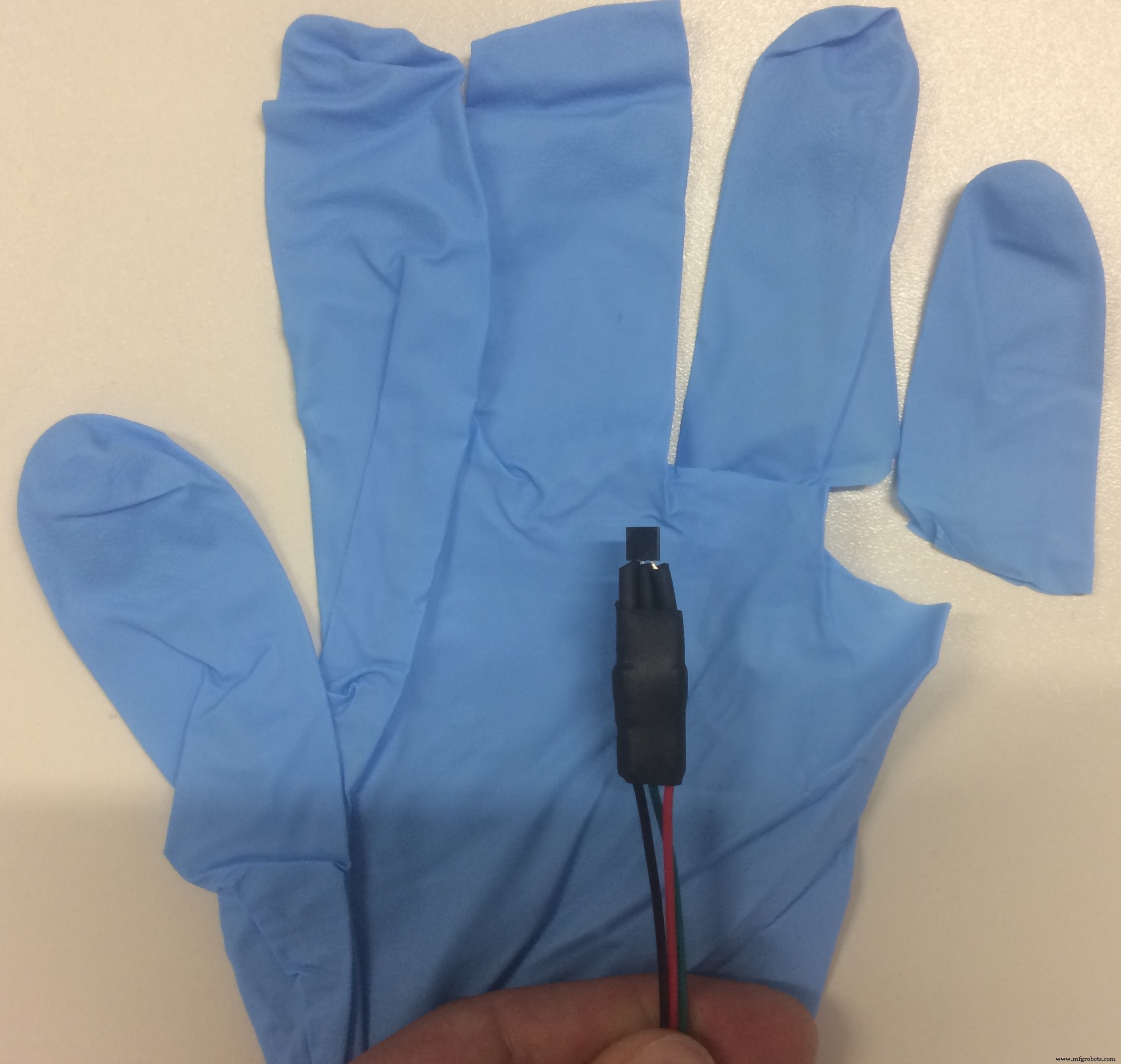
I guess you have got the idea how I am going to waterproof it, right? :D Mama ama engineer!
Said &DONE!
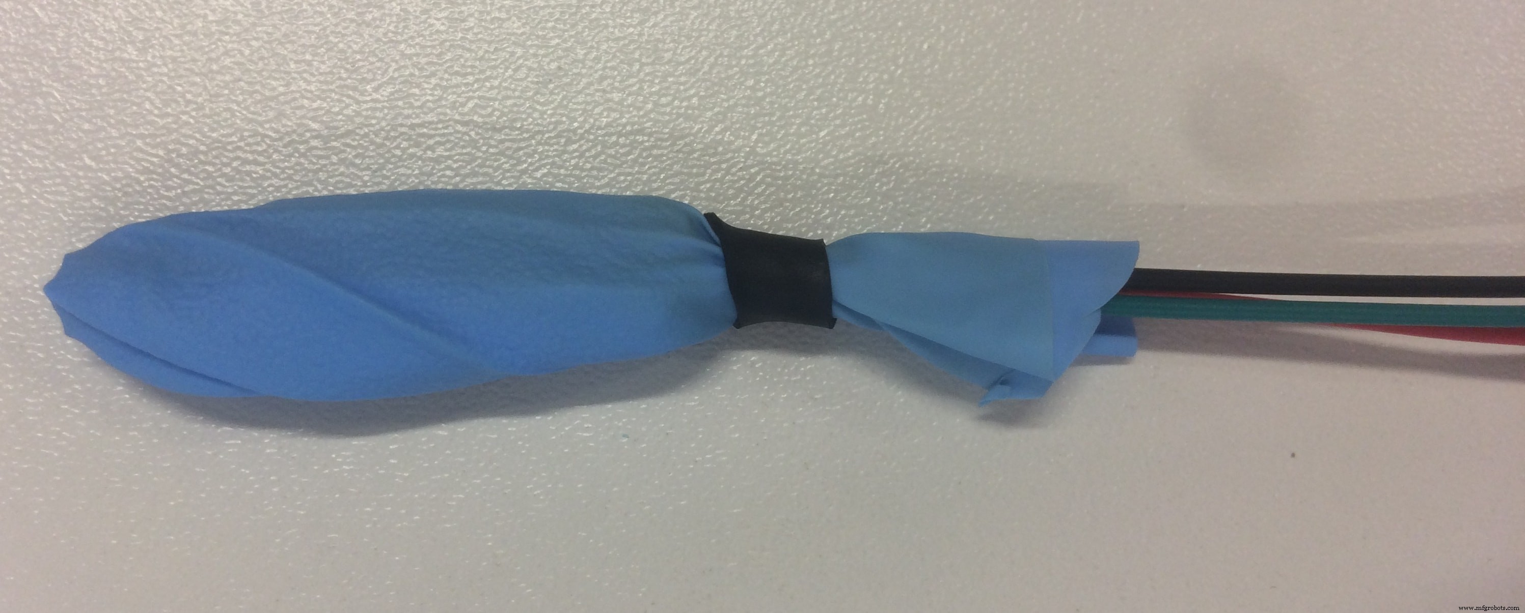
Yeah, I know what it looks like :D but I assure you, its just a hand waterproof sensor. The most important is that it works, and does not leak when submerged in water!
And we go to the next sensor which is LDR =Light Dependent Resistor
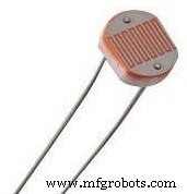
LDR is a passive electronic component, basically a resistor which has a resistance that varies depending of the light intensity. The resistance is very high in darkness, almost high as 1MΩ but when there is light that falls on the LDR, the resistance is falling down to a few KΩ (10-20kΩ @ 10 lux, 2-4kOmega; @ 100 lux) depending on the model.
The LDR gives out an analog voltage when connected to Vcc (5V), which varies in magnitude in direct proportion to the input light intensity on it. That is, the greater the intensity of light, the greater the corresponding voltage from the LDR will be. Since the LDR gives out an analog voltage, it is connected to the analog input pin on the Arduino. The Arduino, with its built-in ADC (Analog to Digital Converter), then converts the analog voltage (from 0-5V) into a digital value in the range of (0-1023). When there is sufficient light in its environment or on its surface, the converted digital values read from the LDR through the Arduino will be in the range of 800-1023.
Here is the sketch code to test the sensor:
int sensorPin =A0; /* select the input pin for LDR */int sensorValue =0; /* variable to store the value coming from the sensor */void setup(void) { Serial.begin(9600); /* start serial port */} void loop(void) { sensorValue =analogRead(sensorPin); // read the value from the sensor // We'll have a few threshholds, qualitatively determined Serial.print("LDR Value ="); Serial.print(sensorValue); if (sensorValue <100) { Serial.println(" (Dark)"); } else if (sensorValue <200) { Serial.println(" (Dim)"); } else if (sensorValue <500) { Serial.println(" (Light)"); } else if (sensorValue <800) { Serial.println(" (Bright)"); } else { Serial.println(" (Very bright)"); } delay(3000);} Next is Water Level Sensor
I want to have a water level sensor in order to receive an alarm when the water container is empty, and its time to add some water. Because I did not think about it in advance, and we did not have any water level sensor in our stock, I decided that I can make my own water sensor!
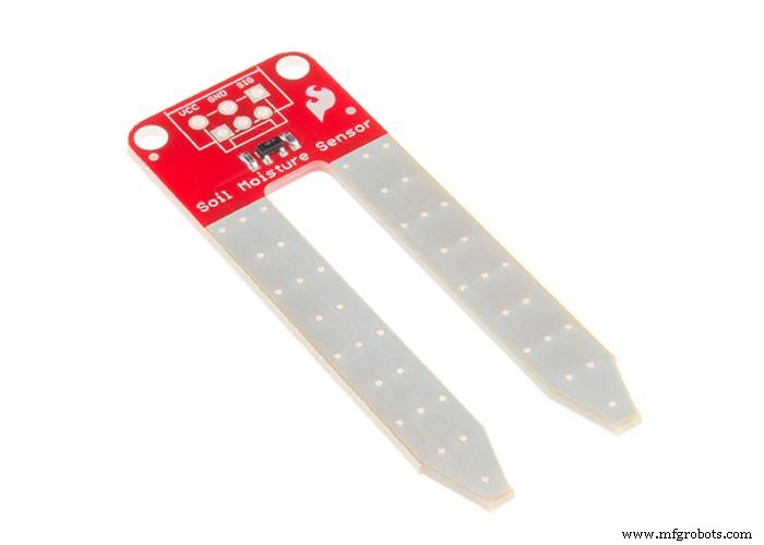
I decided to use the materials available, in my case the Soil Moisture Sensor . The basic principle of the water level sensor is to measure electric conductivity, which is the same for the soil moisture sensor. I thought that If I can calibrate the sensor in a way that will fulfil my requirements, I can use the moisture sensor like an water level sensor) In principle, this is an analog sensor and the data that we will read will be values from 0 to 1024, and the rest is just math!
But as it often happens, the reality is slightly different. When the sensor is not in touch with the water, the analog value is 0, and when I submerge only the tip, the value goes to 800. I used the following sketch to read the values:
/* Print values from analog pin A4 to serial monitor */void setup(){ Serial.begin(9600); }void loop(){ Serial.println(analogRead(A4)); delay(100);} After I can read the values, I calibrated the sensor to give out three different responses:EMPTY! - when the value is 0, LOW when the values are around 800, and Full when the values are more than 900!
Graphic LCD Display
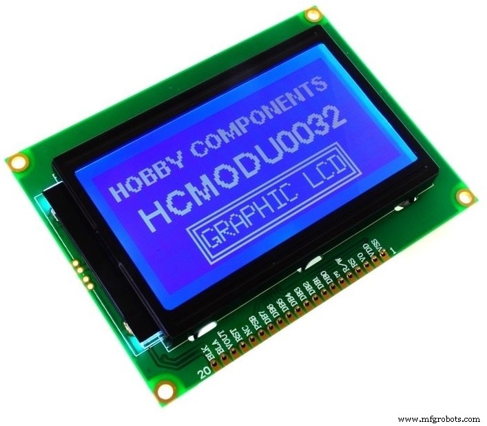
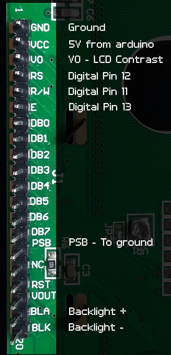
Because usually the LCD displays use a lot of pins, I had to find a way to connect the 128×64 screen in another way, and I DID!!! This way alows using only 3 Digital Pins on the board which is awesome because I may need the rest of the pins for other stuff, and it does not create a mess of wires. I premade the pins for the LCD on my PCB, and this is how I connected everything:
After I connect the LCD, It's time to programm it!
First of all, I have to download the U8glib library from HERE. Another important thing is the declared pins used in the code. The one I used are the following: U8GLIB_ST7920_128X64 u8g(4, 12, 6, U8G_PIN_NONE)
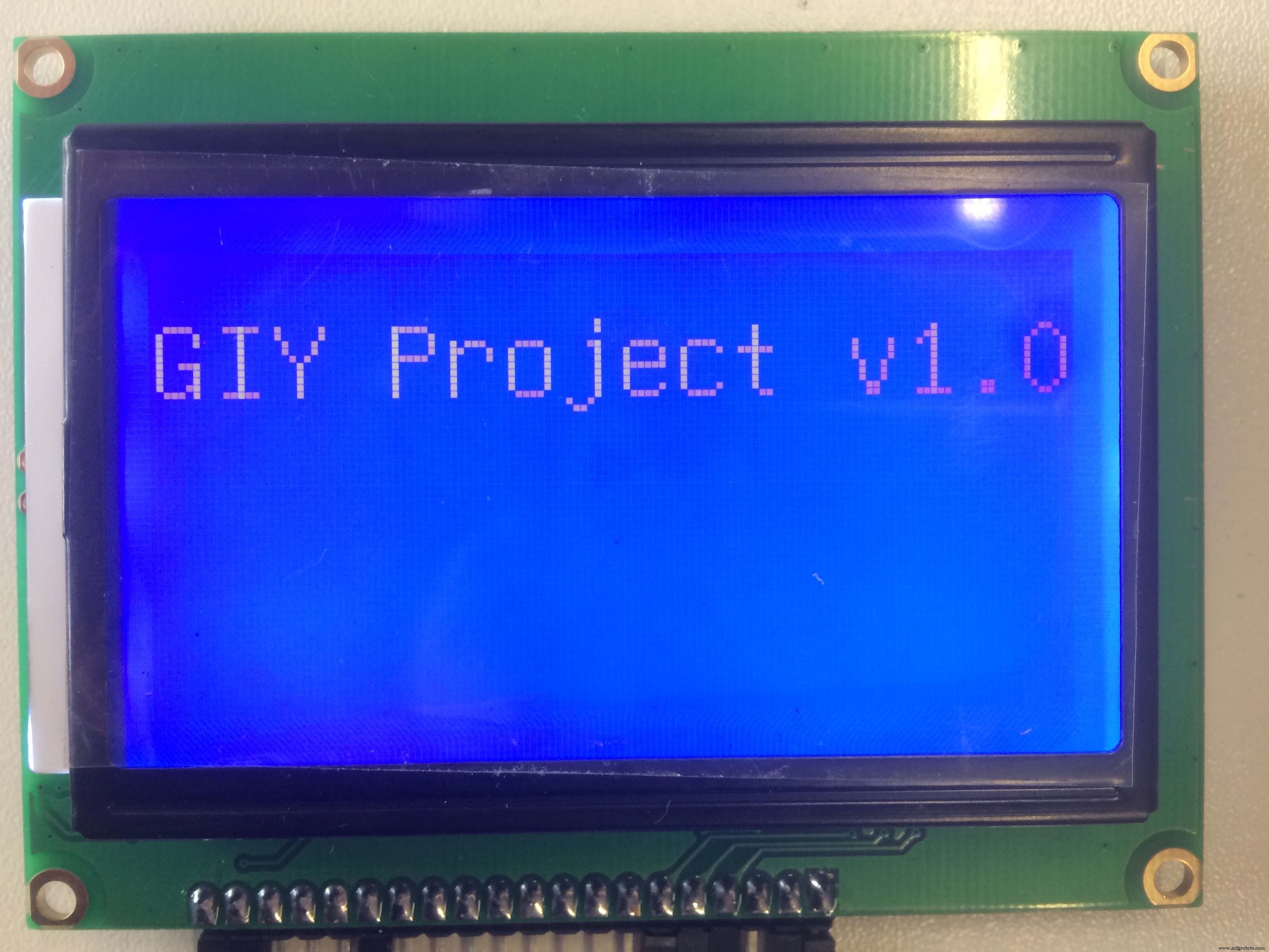
Using the "HELLO WORLD" library example, I came up with this test code:
#include "U8glib.h"U8GLIB_ST7920_128X64 u8g(4, 12, 6, U8G_PIN_NONE);void draw(void) { // graphic commands to redraw the complete screen should be placed here u8g.setFont(u8g_font_unifont); u8g.setPrintPos(0, 20); // call procedure from base class, http://arduino.cc/en/Serial/Print u8g.print("GIY Project v1.0!");}void setup(void) { // flip screen, if required // u8g.setRot180();}void loop(void) { // picture loop u8g.firstPage();做{画(); } while( u8g.nextPage() ); // rebuild the picture after some delay delay(500);} And this is what I get:
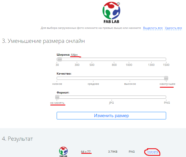
One cool idea that came to my mind was to display the FabLab logo for some seconds, all the time when the display is powered. I spent quite a lot of time on doing this, but I finally did it! In order to display it on the Graphic LCD, I had to have a (.bmp) format picture, and display it as a bitmap.
First thing which I did was download the FabLab logo from the internet as a (.png) file, and reduce it significantly in size, so it fits my small LCD borders. I used the following online service to do that:LINK
These are the configurations I used:
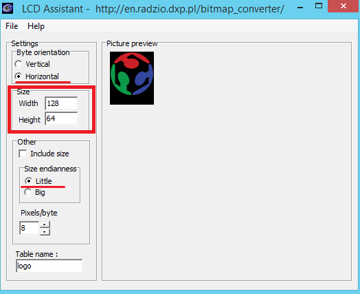
The next step is to convert my small picture into (.bmp) format. I used the following online service to do that:LINK
Now, after I have my (.bmp) file, in order to place it into my code, I have to convert it into HEX 大批。 I used a nice tool called LCD Assistant . To load up an image in LCD Assistant, go to File> Load Image. A preview of the image should open up, make sure it’s the right size – 128 pixels wide, 64 pixels tall . Also make sure the Byte orientation is set to Horizontal and the Size endianness is set to Little . These are the configurations for my LCD Display:
Then I go to File> Save output to generate a temporary text 文件。 Open that text file to have a look at my shiny new array.
pH Sensor
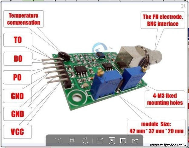
I should admit that this is the most tricky sensor from all that I played with! It is really hard to find any info about the sensor which I am using (logo ph sensor v1.1) , so I decided to make a detailed description about it!
The probe is like a (tiny) battery when placed in a liquid. Depending the pH it output a positive or negative voltage of a couple of millivolts. This value is too small and other tech stuff like impedance make it unusable directly with an Arduino, that's why you need an "op amp". The op amp board just convert the millivolts of the probe into to something acceptable for Arduino (positive between 0 and 5v).
There are 3 common buffer solutions used for pH measurement:pH 4.01, pH 6.86 and pH 9.18 (7.0 and 10.0 exists). I suggest the powder instead the liquid because it's cheaper, expire after longer and the powder can't be contaminated (vs bottle). You should read the product instructions but usually you have to put the content of the bag into 250ml of water and stir. You can use any water with an average pH (6-8) because the powder will saturate the water at the correct pH level. I personally use tap water (pH 7.4) and didn't see any difference between distilled, and demineralized water. Buffers are not stable in the time, this means that you cannot keep the solution for weeks or months.
Now let's talk more about the sensor that I am using!
- Pin To:Should be the temperature but I can't make it work
- Pin Po:Analog input signal
- Pin To:Should be the temperature but I can't make it work
- Pin Do:High/Low 3.3v adjustable limit.
- Pin G/GND:Probe ground. It is useful when the ground is not the same as your Arduino. In some circumstances the ground voltage of the liquid to measure can be different.
- Pin G/GND:Power ground (direct from the board).
- Pin V+/VCC:Input power 5V DC (direct from the board).
- Blue potentiometer (close to BNC):pH offset.
- Blue potentiometer (close to pins):limit adjustment.
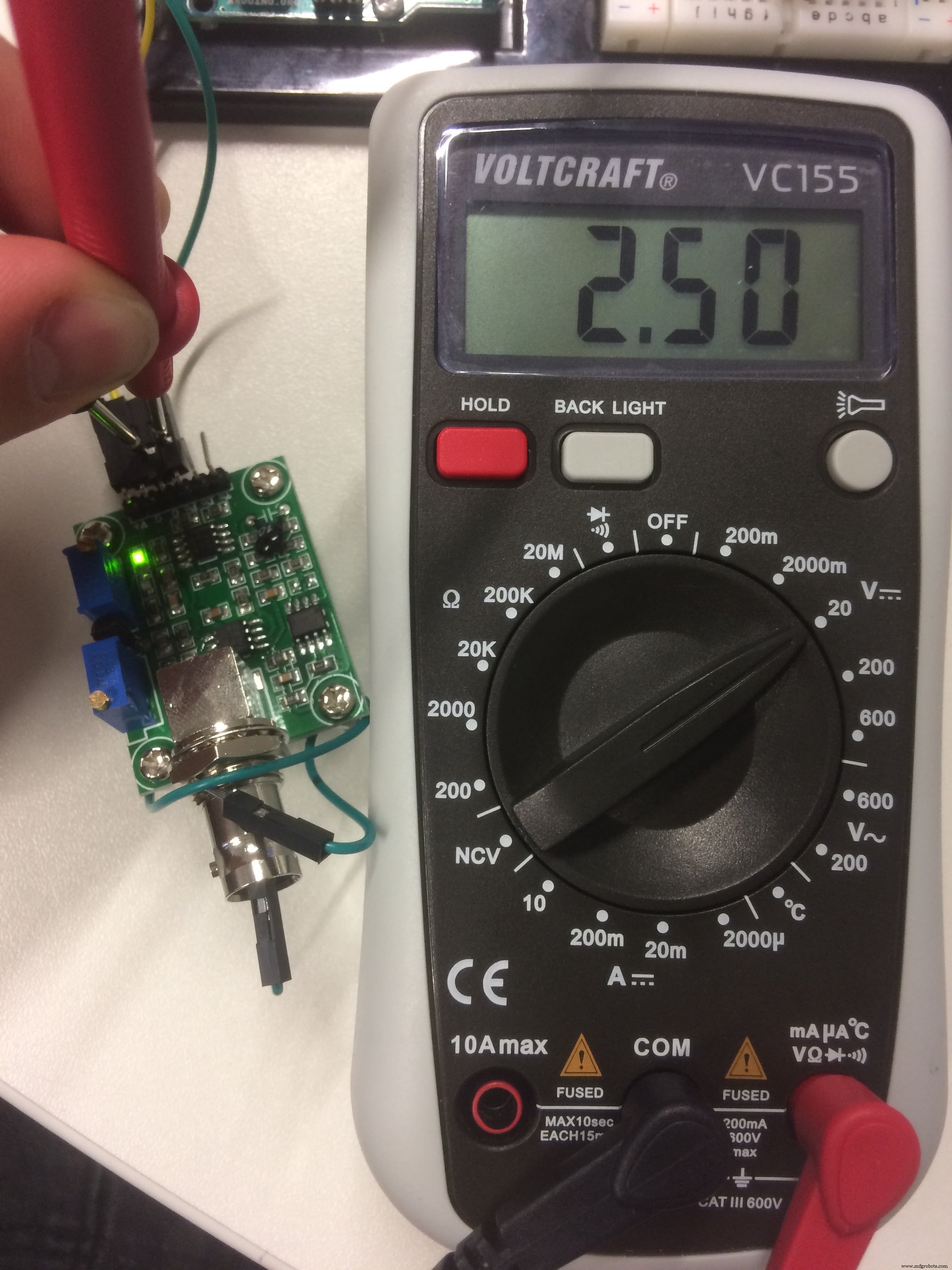
Now let's try to calibrate the sensor! There are 2 different parameters, the "offset" value and the "step" value
The offset is the shifting of all pH values to a specific voltage range. If a pH 7 output a voltage of 2.2v and pH 8 a voltage of 2.1v, then a shift of +0.3v move the pH 7 to 2.5v and the pH 8 to 2.4v. This can be done on the board or via software but it's probably easier on the board because it's probe independent and there are less programming to do.
Connect GND (both) and Vcc to Arduino GND and 5v. Remove the probe and do a short circuit between the the small BNC hole and the external part of BNC. Put a voltmeter (or Arduino) to measure the voltage between GND and Po. Adjust the pot (close BNC) until the output is 2.5v. Now the pH 7 have an exact value of 2.5v (511 with analogRead function) because the probe will output 0 millivolt.
To calibrate the steps I need one or more buffer solutions depending on the range and precision required. Ideally it is better to know the range of the measure with the system. I use water between pH 5 and pH 7, then I choose the buffer 4.01 (and 6.86 to verify my stuff). If you usually measure pH between 8 and 10 choose buffer 9.18 (eventually 6.86 also).
I connect the (clean) probe and put it in the buffer, then let it stabilize for a minute. I know it's stable when it goes up and down (3.04 then 3.05 then 3.03 then 3.04).Take note of the voltmeter (or Arduino) value, in my example it's 3.05v.
That's all, now I can use it with the code below.
int ph_pin =A7; //This is the pin number connected to Povoid setup() { Serial.begin(9600);}void loop() { int measure =analogRead(ph_pin); Serial.print("Measure:"); Serial.print(measure); double voltage =5 / 1024.0 * measure; //classic digital to voltage conversion Serial.print("\tVoltage:"); Serial.print(voltage, 3); // PH_step =(voltage@PH7 - voltage@PH4) / (PH7 - PH4) // PH_probe =PH7 - ((voltage@PH7 - voltage@probe) / PH_step) float Po =7 + ((2.5 - voltage) / 0.18); Serial.print("\tPH:"); Serial.print(Po, 3); Serial.println(""); delay(2000);} The PH_step calculation is quite simple. I take the difference between the two known voltage, in my example 2.5v@pH7 and 3.05v@pH4.01 which is -0.55v. It's the voltage range equivalent of the pH range from 7 to 4.01, which is 2.99 pH units. A small division of the voltage by pH units gives a volts per pH number (0, 1839... in my case).
The PH_probe is calculated by taking the known pH 7 voltage (2.5v) where we add some PH_step to match the probe voltage. This means that a pH of 8 has a voltage value of 2.5v (pH 7) + 0.1839 (1 unit/step); pH 9 then is 2.5v + 0.1839 + 0.1839 =2.87v.
No magic, JUST MATH :D
MOSFET output:
I connected the RGB LED stripe and the Ultrasonic Atomizer to the MOSFET circuit outputs, which are controlled by digital pins. For the LED lights, I stated in the setup digitalWrite (LED, HIGH); , which means that the LED will switch on all the time when the system is powered. For the Fog maker, I made an If function depending on the water level value. If there is water, the fog maker is ON, if there is no water, EMPTY!, then the fog is OFF!
Now Let's put things together!
Here I came up with my final code:
#include "dht.h"#include "U8glib.h"#include #include #define DHT11_PIN 2 // what digital pin we're connected to#define ONE_WIRE_BUS 3#define WATER_LEVEL A4#define LDR_PIN A3#define PH_PIN A5#define GROW_LIGHT 10#define FOG_PUMP 13int waterLevel;int LightLevel;int pH;dht DHT;OneWire oneWire(ONE_WIRE_BUS); DallasTemperature waterTemp(&oneWire);U8GLIB_ST7920_128X64 u8g(4, 12, 6, U8G_PIN_NONE);const unsigned char logo [] PROGMEM ={0xFF, 0xFF, 0xFF, 0xFE, 0x7F, 0xFF, 0xFF, 0xFF, 0x00, 0x00, 0x00, 0x00, 0x00, 0x00, 0x00, 0x00,0xFF, 0xFF, 0xFF, 0x00, 0x00, 0xFF, 0xFF, 0xFF, 0x00, 0x00, 0x00, 0x00, 0x00, 0x00, 0x00, 0x00,0xFF, 0xFF, 0xF8, 0x00, 0x00, 0x1F, 0xFF, 0xFF, 0x00, 0x00, 0x00, 0x00, 0x00, 0x00, 0x00, 0x00,0xFF, 0xFF, 0xC0, 0x00, 0x00, 0x03, 0xFF, 0xFF, 0x00, 0x00, 0x00, 0x00, 0x00, 0x00, 0x00, 0x00,0xFF, 0xFF, 0x00, 0x00, 0x00, 0x00, 0xFF, 0xFF, 0x00, 0x00, 0x00, 0x00, 0x00, 0x00, 0x00, 0x00,0xFF, 0xFE, 0x00, 0x03, 0xC0, 0x00, 0x7F, 0xFF, 0x00, 0x00, 0x00, 0x00, 0x00, 0x00, 0x00, 0x00,0xFF, 0xF8, 0x00, 0x07, 0xE0, 0x00, 0x3F, 0xFF, 0x00, 0x00, 0x00, 0x00, 0x00, 0x00, 0x00, 0x00,0xFF, 0xF0, 0x00, 0x1F, 0xF8, 0x00, 0x0F, 0xFF, 0x00, 0x00, 0x00, 0x00, 0x00, 0x00, 0x00, 0x00,0xFF, 0xE0, 0x00, 0x3F, 0xFE, 0x00, 0x07, 0xFF, 0x00, 0x00, 0x00, 0x00, 0x00, 0x00, 0x00, 0x00,0xFF, 0xC0, 0x00, 0x18, 0x1F, 0x00, 0x03, 0xFF, 0x00, 0x00, 0x00, 0x00, 0x00, 0x00, 0x00, 0x00,0xFF, 0x80, 0x00, 0x00, 0x03, 0xC0, 0x01, 0xFF, 0x00, 0x00, 0x00, 0x00, 0x00, 0x00, 0x00, 0x00,0xFF, 0x00, 0x00, 0x00, 0x00, 0xF0, 0x00, 0xFF, 0x00, 0x00, 0x00, 0x00, 0x00, 0x00, 0x00, 0x00,0xFE, 0x00, 0x00, 0x00, 0x00, 0x7C, 0x00, 0x7F, 0x00, 0x00, 0x00, 0x00, 0x00, 0x00, 0x00, 0x00,0xFC, 0x00, 0x00, 0x00, 0x00, 0x3E, 0x00, 0x7F, 0x00, 0x00, 0x00, 0x00, 0x00, 0x00, 0x00, 0x00,0xFC, 0x03, 0x80, 0x00, 0x00, 0x3F, 0x80, 0x3F, 0x00, 0x00, 0x00, 0x00, 0x00, 0x00, 0x00, 0x00,0xF8, 0x07, 0xE0, 0x00, 0x00, 0x1F, 0xE0, 0x1F, 0x00, 0x00, 0x00, 0x00, 0x00, 0x00, 0x00, 0x00,0xFC, 0x1F, 0xF0, 0x00, 0x00, 0x1F, 0xF0, 0x1F, 0x00, 0x00, 0x00, 0x00, 0x00, 0x00, 0x00, 0x00,0xF0, 0x3F, 0xF0, 0x00, 0x00, 0x1F, 0xFC, 0x0F, 0x00, 0x00, 0x00, 0x00, 0x00, 0x00, 0x00, 0x00,0xF0, 0xFF, 0xF0, 0x00, 0x00, 0x1F, 0xFF, 0x0F, 0x00, 0x00, 0x00, 0x00, 0x00, 0x00, 0x00, 0x00,0xE0, 0xFF, 0xF0, 0x00, 0x00, 0x3F, 0xFF, 0x07, 0x00, 0x00, 0x00, 0x00, 0x00, 0x00, 0x00, 0x00,0xE0, 0xFF, 0xF0, 0x00, 0x00, 0x3F, 0xFF, 0x07, 0x00, 0x00, 0x00, 0x00, 0x00, 0x00, 0x00, 0x00,0xC0, 0xFF, 0xF8, 0x00, 0x00, 0x7F, 0xFF, 0x03, 0x00, 0x00, 0x00, 0x00, 0x00, 0x00, 0x00, 0x00,0xC0, 0xFF, 0xFC, 0x00, 0x00, 0xFF, 0xFF, 0x03, 0x00, 0x00, 0x00, 0x00, 0x00, 0x00, 0x00, 0x00,0xC0, 0xFF, 0xFF, 0x00, 0x01, 0xFF, 0xFF, 0x03, 0x00, 0x00, 0x00, 0x00, 0x00, 0x00, 0x00, 0x00,0x80, 0xFF, 0xFF, 0xC0, 0x07, 0xFF, 0xFF, 0x01, 0x00, 0x00, 0x00, 0x00, 0x00, 0x00, 0x00, 0x00,0x80, 0xFF, 0xFF, 0xFF, 0xFF, 0xFF, 0xFF, 0x01, 0x00, 0x00, 0x00, 0x00, 0x00, 0x00, 0x00, 0x00,0x80, 0xFF, 0xFF, 0xFF, 0xFF, 0xFF, 0xFF, 0x01, 0x00, 0x00, 0x00, 0x00, 0x00, 0x00, 0x00, 0x00,0x80, 0xFF, 0xFF, 0xFF, 0xFF, 0xFF, 0xFF, 0x01, 0x00, 0x00, 0x00, 0x00, 0x00, 0x00, 0x00, 0x00,0x80, 0xFE, 0x1F, 0xFF, 0xFF, 0xF0, 0x3C, 0x01, 0x00, 0x00, 0x00, 0x00, 0x00, 0x00, 0x00, 0x00,0x80, 0xF8, 0x03, 0xFF, 0xFF, 0xC0, 0x10, 0x01, 0x00, 0x00, 0x00, 0x00, 0x00, 0x00, 0x00, 0x00,0x80, 0xF0, 0x01, 0xFF, 0xFF, 0x80, 0x00, 0x01, 0x00, 0x00, 0x00, 0x00, 0x00, 0x00, 0x00, 0x00,0x00, 0xF0, 0x00, 0xFF, 0xFF, 0x00, 0x00, 0x01, 0x00, 0x00, 0x00, 0x00, 0x00, 0x00, 0x00, 0x00,0x00, 0xE0, 0x00, 0x7F, 0xFE, 0x00, 0x00, 0x01, 0x00, 0x00, 0x00, 0x00, 0x00, 0x00, 0x00, 0x00,0x80, 0xE0, 0x00, 0x3F, 0xFC, 0x00, 0x00, 0x01, 0x00, 0x00, 0x00, 0x00, 0x00, 0x00, 0x00, 0x00,0x80, 0xE0, 0x00, 0x1F, 0xFC, 0x00, 0x00, 0x01, 0x00, 0x00, 0x00, 0x00, 0x00, 0x00, 0x00, 0x00,0x80, 0xE0, 0x00, 0x1F, 0xF8, 0x00, 0x00, 0x01, 0x00, 0x00, 0x00, 0x00, 0x00, 0x00, 0x00, 0x00,0x80, 0xE0, 0x00, 0x0F, 0xF8, 0x00, 0x00, 0x01, 0x00, 0x00, 0x00, 0x00, 0x00, 0x00, 0x00, 0x00,0x80, 0xE0, 0x00, 0x0F, 0xF0, 0x00, 0x00, 0x01, 0x00, 0x00, 0x00, 0x00, 0x00, 0x00, 0x00, 0x00,0x80, 0xE0, 0x00, 0x0F, 0xF0, 0x00, 0x01, 0x01, 0x00, 0x00, 0x00, 0x00, 0x00, 0x00, 0x00, 0x00,0x80, 0xE0, 0x00, 0x07, 0xF0, 0x00, 0x07, 0x01, 0x00, 0x00, 0x00, 0x00, 0x00, 0x00, 0x00, 0x00,0xC0, 0xF0, 0x00, 0x07, 0xF0, 0x00, 0x07, 0x03, 0x00, 0x00, 0x00, 0x00, 0x00, 0x00, 0x00, 0x00,0xC0, 0xF0, 0x00, 0x07, 0xF0, 0x00, 0x0F, 0x03, 0x00, 0x00, 0x00, 0x00, 0x00, 0x00, 0x00, 0x00,0xC0, 0xF8, 0x00, 0x07, 0xF0, 0x00, 0x0F, 0x03, 0x00, 0x00, 0x00, 0x00, 0x00, 0x00, 0x00, 0x00,0xC0, 0xF8, 0x00, 0x07, 0xF0, 0x00, 0x1F, 0x07, 0x00, 0x00, 0x00, 0x00, 0x00, 0x00, 0x00, 0x00,0xE0, 0xFC, 0x00, 0x07, 0xF0, 0x00, 0x1F, 0x07, 0x00, 0x00, 0x00, 0x00, 0x00, 0x00, 0x00, 0x00,0xE0, 0xFE, 0x00, 0x0F, 0xF0, 0x00, 0x3F, 0x07, 0x00, 0x00, 0x00, 0x00, 0x00, 0x00, 0x00, 0x00,0xF0, 0x3E, 0x00, 0x0F, 0xF0, 0x00, 0x7C, 0x0F, 0x00, 0x00, 0x00, 0x00, 0x00, 0x00, 0x00, 0x00,0xF0, 0x1E, 0x00, 0x1F, 0xF8, 0x00, 0xF8, 0x0F, 0x00, 0x00, 0x00, 0x00, 0x00, 0x00, 0x00, 0x00,0xF8, 0x06, 0x00, 0x1F, 0xFC, 0x01, 0xE0, 0x1F, 0x00, 0x00, 0x00, 0x00, 0x00, 0x00, 0x00, 0x00,0xFC, 0x00, 0x00, 0x7F, 0xFF, 0x0F, 0x80, 0x3F, 0x00, 0x00, 0x00, 0x00, 0x00, 0x00, 0x00, 0x00,0xFC, 0x00, 0x00, 0x7F, 0xFF, 0xFF, 0x00, 0x3F, 0x00, 0x00, 0x00, 0x00, 0x00, 0x00, 0x00, 0x00,0xFE, 0x00, 0x00, 0x7F, 0xFF, 0xFC, 0x00, 0x7F, 0x00, 0x00, 0x00, 0x00, 0x00, 0x00, 0x00, 0x00,0xFF, 0x00, 0x00, 0x7F, 0xFF, 0xF0, 0x00, 0xFF, 0x00, 0x00, 0x00, 0x00, 0x00, 0x00, 0x00, 0x00,0xFF, 0x80, 0x00, 0x7F, 0xFF, 0xC0, 0x01, 0xFF, 0x00, 0x00, 0x00, 0x00, 0x00, 0x00, 0x00, 0x00,0xFF, 0xC0, 0x00, 0x7F, 0xFF, 0x80, 0x03, 0xFF, 0x00, 0x00, 0x00, 0x00, 0x00, 0x00, 0x00, 0x00,0xFF, 0xE0, 0x00, 0x7F, 0xFE, 0x00, 0x07, 0xFF, 0x00, 0x00, 0x00, 0x00, 0x00, 0x00, 0x00, 0x00,0xFF, 0xF0, 0x00, 0x1F, 0xF8, 0x00, 0x0F, 0xFF, 0x00, 0x00, 0x00, 0x00, 0x00, 0x00, 0x00, 0x00,0xFF, 0xF8, 0x00, 0x0F, 0xF0, 0x00, 0x1F, 0xFF, 0x00, 0x00, 0x00, 0x00, 0x00, 0x00, 0x00, 0x00,0xFF, 0xFC, 0x00, 0x03, 0xC0, 0x00, 0x3F, 0xFF, 0x00, 0x00, 0x00, 0x00, 0x00, 0x00, 0x00, 0x00,0xFF, 0xFF, 0x00, 0x00, 0x00, 0x00, 0xFF, 0xFF, 0x00, 0x00, 0x00, 0x00, 0x00, 0x00, 0x00, 0x00,0xFF, 0xFF, 0xC0, 0x00, 0x00, 0x03, 0xFF, 0xFF, 0x00, 0x00, 0x00, 0x00, 0x00, 0x00, 0x00, 0x00,0xFF, 0xFF, 0xF0, 0x00, 0x00, 0x1F, 0xFF, 0xFF, 0x00, 0x00, 0x00, 0x00, 0x00, 0x00, 0x00, 0x00,0xFF, 0xFF, 0xFE, 0x00, 0x00, 0x7F, 0xFF, 0xFF, 0x00, 0x00, 0x00, 0x00, 0x00, 0x00, 0x00, 0x00,0xFF, 0xFF, 0xFF, 0xFD, 0x3F, 0xFF, 0xFF, 0xFF, 0x00, 0x00, 0x00, 0x00, 0x00, 0x00, 0x00, 0x00};bool first;float hum =0.0;double T=0.0;void dht_test(float * humPerc);void setup(void) { waterTemp.begin(); pinMode (GROW_LIGHT, OUTPUT); pinMode (FOG_PUMP, OUTPUT); digitalWrite (GROW_LIGHT, HIGH); first =true; // assign default color value if ( u8g.getMode() ==U8G_MODE_R3G3B2 ) { u8g.setColorIndex(255); // white } else if ( u8g.getMode() ==U8G_MODE_GRAY2BIT ) { u8g.setColorIndex(3); // max intensity } else if ( u8g.getMode() ==U8G_MODE_BW ) { u8g.setColorIndex(1); // pixel on } else if ( u8g.getMode() ==U8G_MODE_HICOLOR ) { u8g.setHiColorByRGB(255,255,255); } // picture loop u8g.firstPage(); do { u8g.drawBitmapP( 32, 0, 16, 64, logo); } while( u8g.nextPage() ); dht_test(&hum);}void RefreshDisplay(float * humPerc, double *T, int *WL, int *LL, int *pH_value) { u8g.setFont(u8g_font_fub11); u8g.setFontRefHeightExtendedText(); u8g.setDefaultForegroundColor(); u8g.setFontPosTop(); u8g.drawStr( 4, 0, "Hum%"); u8g.setPrintPos( 68, 0); u8g.print( *humPerc); u8g.drawStr( 4, 15, "Temp"); u8g.setPrintPos( 68, 15); u8g.print( *T); u8g.drawStr( 4, 30, "Wlvl"); if (*WL ==0){ u8g.drawStr (68, 30,"EMPTY!"); digitalWrite (FOG_PUMP, LOW); } else{ if (*WL <800) u8g.drawStr (68, 30,"LOW"); else { digitalWrite(FOG_PUMP, HIGH); u8g.drawStr (68, 30,"HIGH"); } } if (*LL <100) { u8g.drawStr (68, 45,"Dark"); } else if (*LL <200) { u8g.drawStr (68, 45,"Dim"); } else if (*LL <500) { u8g.drawStr (68, 45, "Light"); } else if (*LL <800) { u8g.drawStr (68, 45,"Bright"); } else { u8g.drawStr (68, 45,"2Bright"); } double voltage =5.0 / 1024.0 * (*pH_value); float Po =7 + ((2.5 - voltage) / 0.18); u8g.drawStr (4, 45,"pH"); u8g.setPrintPos( 28, 45); u8g.print( Po); }void loop(void) {waterTemp.requestTemperatures();T =waterTemp.getTempCByIndex(0);waterLevel =analogRead(WATER_LEVEL);LightLevel =analogRead(LDR_PIN);pH =analogRead (PH_PIN);char status;int chk =DHT.read11(DHT11_PIN);hum =DHT.humidity; dht_test(&hum); if(first) { first =false; } else { u8g.firstPage(); do { RefreshDisplay(&hum, &T,&waterLevel, &LightLevel, &pH); } while( u8g.nextPage() ); }}void dht_test(float * humPerc) { // Wait a few seconds between measurements. delay(1000);}
Download Files:
GIY Final Code (.ino)
3D Design &3D Printing
Actually for my final system, I used a lot of 3D design and 3D printing technique. I used two different printers, and played a lot with the settings until I got the desired result!
For 3D design, I used which as I mentioned before, is my favourite CAD software! I will not go too much into details of how to create simple shapes, and extrude objects, all this could be found during my Computer-Aided Design week, where I learned how to use diferent softwares, as well as 3D Scanning and Printing week.

The main task was to design the physical appearence of my system! The challenge was that I wanted it to look SEXY!!!
The aesthetics was a very important criteria, as well as functionality! The system should also be assemblable, which makes it even more challenging. I also wanted to integrate the skills which I learned like 3D printing, CNC milling, Laser cutting etc.
Before designing it in the digital world, I made a simple sketch on paper! Here it is:
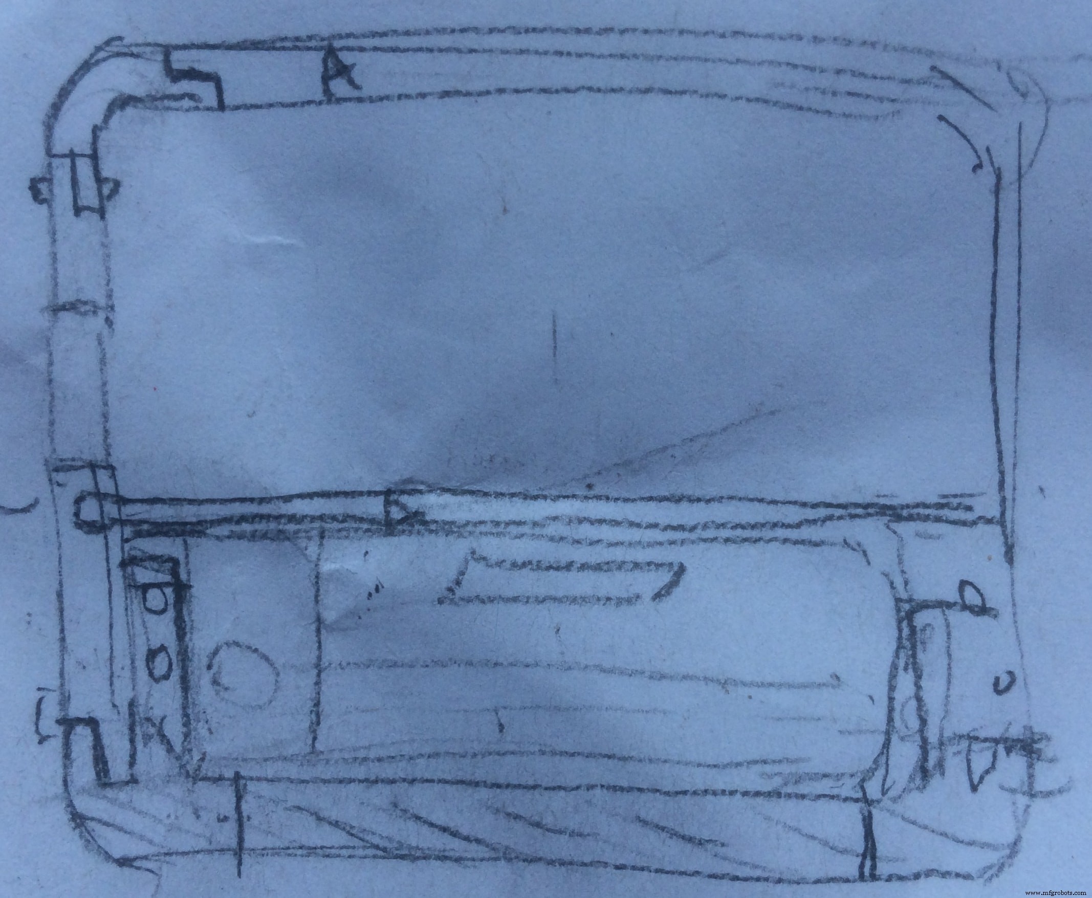
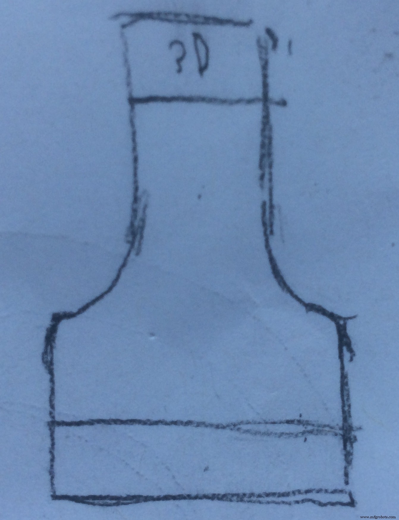
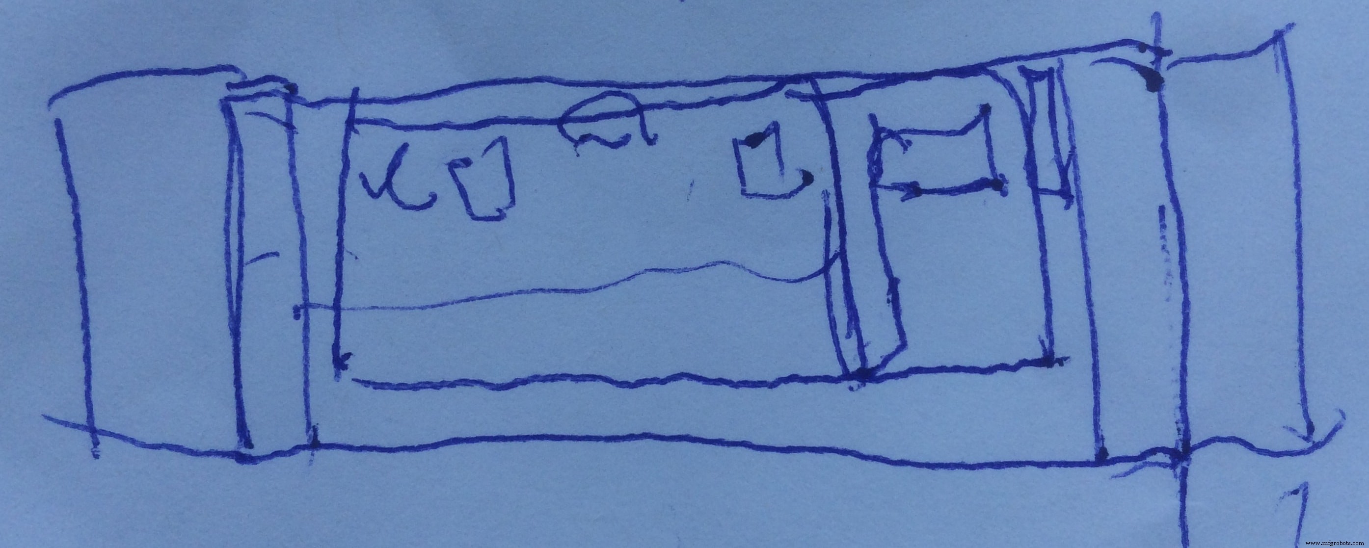
And this is the final 3D design:
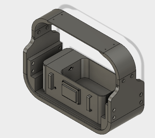
My sexy ass system :D
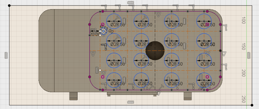
First thing which I designed was the water container . Here it is:
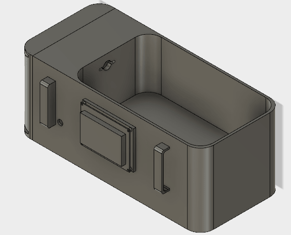
It incorporates several features! First, there is enough space for plants to grow, as well as in the middle I made a hole to place the Ultrasonic Atomizer. It is done because I wanted to level the fogger with the container. The thing is that the water level should be above the fogger by 2cm, so all the water which is leveled with the fogger hight, will not be used (waste)! So if I place the fogger below the container level, I have a water zero level exactly at the point where it should be, zero for the container =2cm above the fogger. In this way, all the water is used!
I also considered the hight of the container. Actually, all the dimensions of the container are measured during the experimental stage!
As you can see, I made a hole on the wall, which will be used for the cables from sensors placed in the water to hide into the electronics section. In the front of the container, I made the slot to attach the graphic display. I also designed some handles to easily remove the container when need!
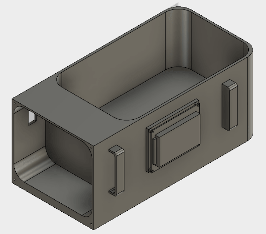
From this perspective, you can see the electronics section. Now its opened, but I also designed a lid to close it. Inside the electronics section, I designed a hole to have access to power and program the board
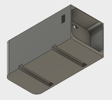
On the bottom side I designed sliders which will be attached to the rest of the system, and make it easier to remove the container when needed, it will also play a role of fixation of the container in place!
And now Let's Print It!
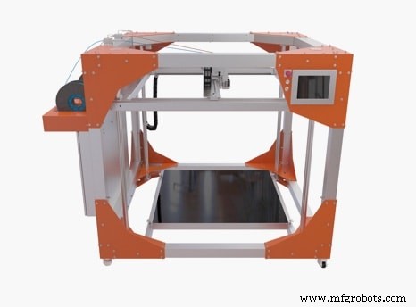
I can proudly announce that the printer which I will be using is called BigRep 3D Printer , only available in our FabLab Kamp-Lintfort. It has a capacity of one cubic meter, and provides the largest FFF build volume for professional and industrial use.
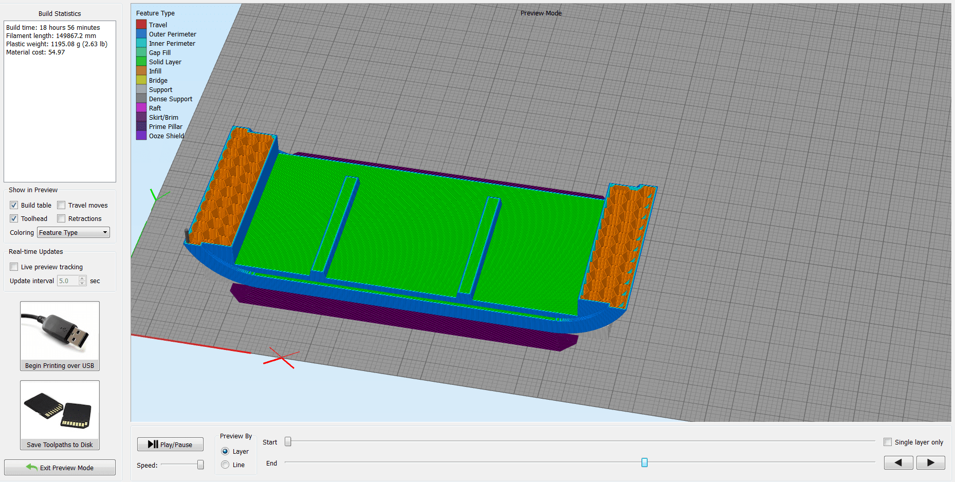
The slicing software which I use is Simplify3D , one of the most advanced slicing tools, in my opinion, with a lot of configurations and options.

I do not think that there is a right and a wrong way to print something, you just have to play with the settings until you find the best options for the specific object to print.
Because this printer is new, there are not too many testings made. So, I had to experiment with the settings, and try, try and again try...
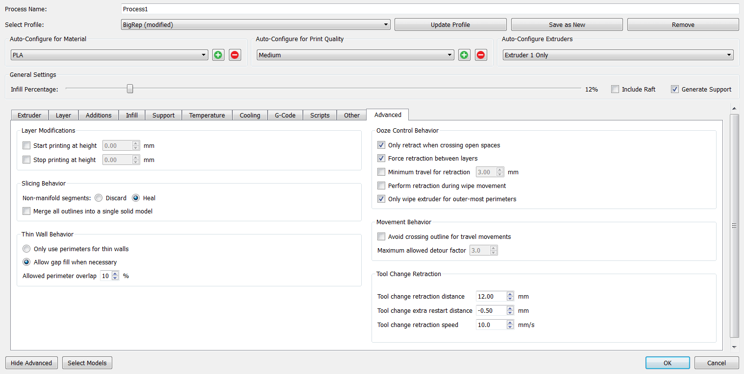
I will show bellow the settings that I will be using for my water container print, but some of them are intuitive.
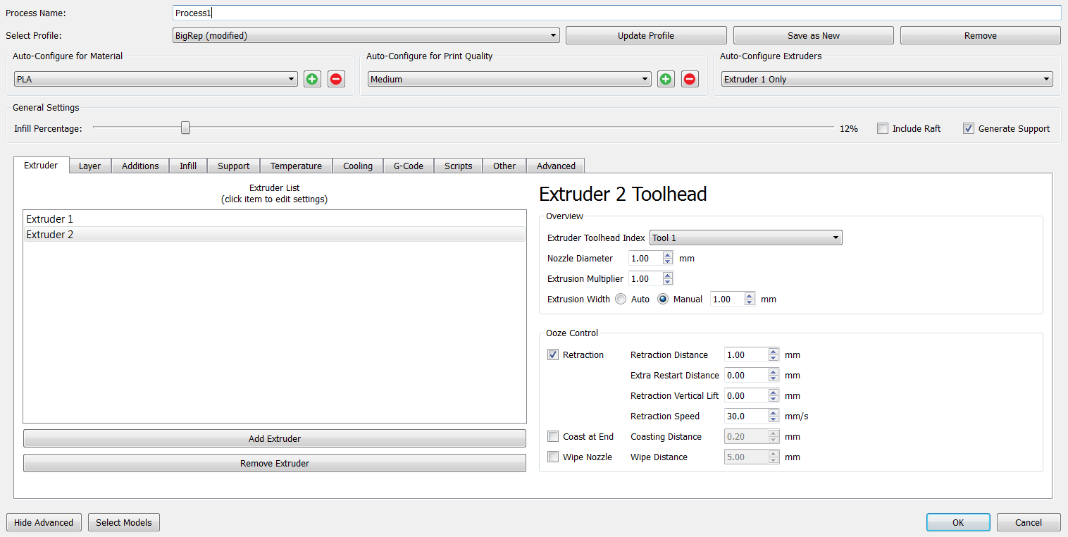
I choose the Tool1 , because the BigRep Printer has two nozzels with two different filaments, and I have to specify which nozzel I want to use, as well as the nozzle diameter and the rest of the settings.
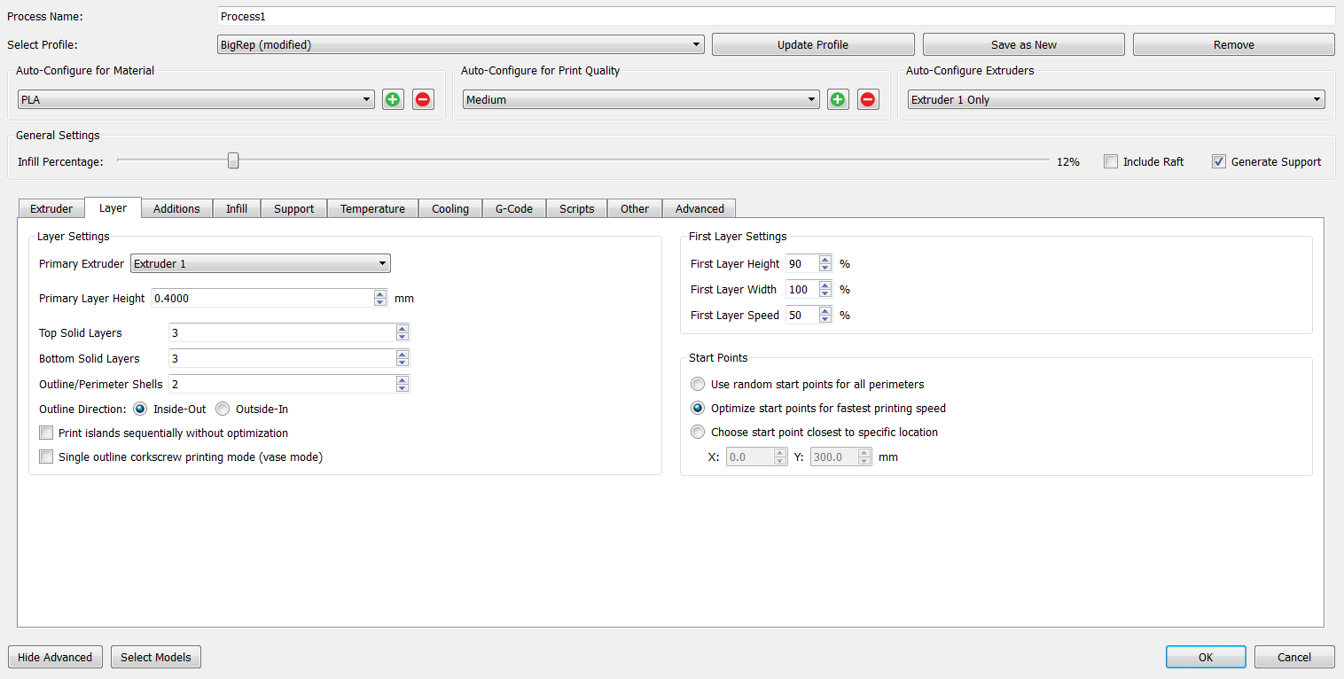
Layer:
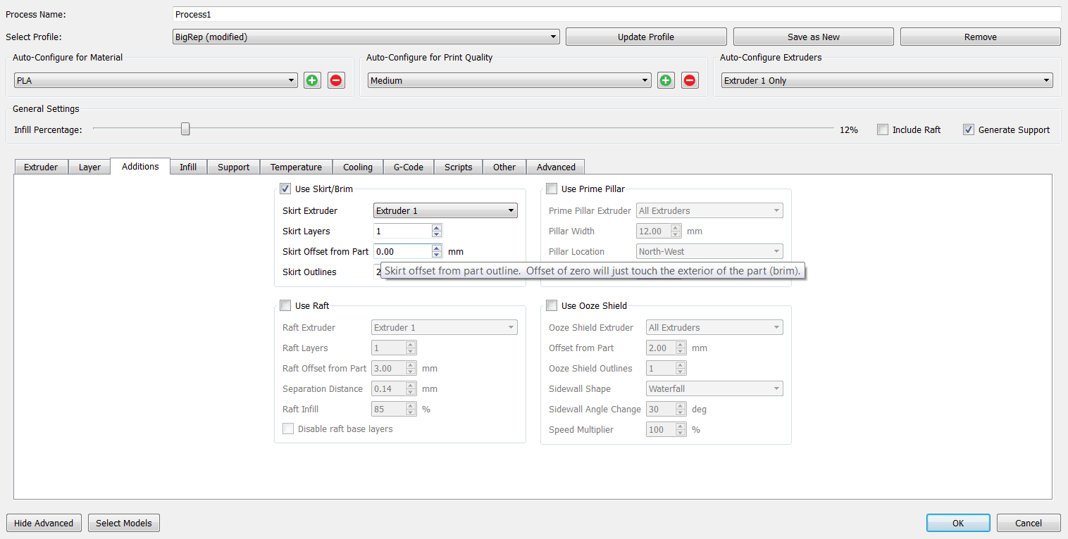
Additions:
Infill:
支持:
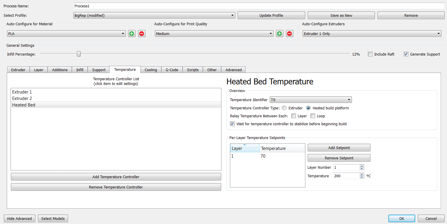
Temperature:
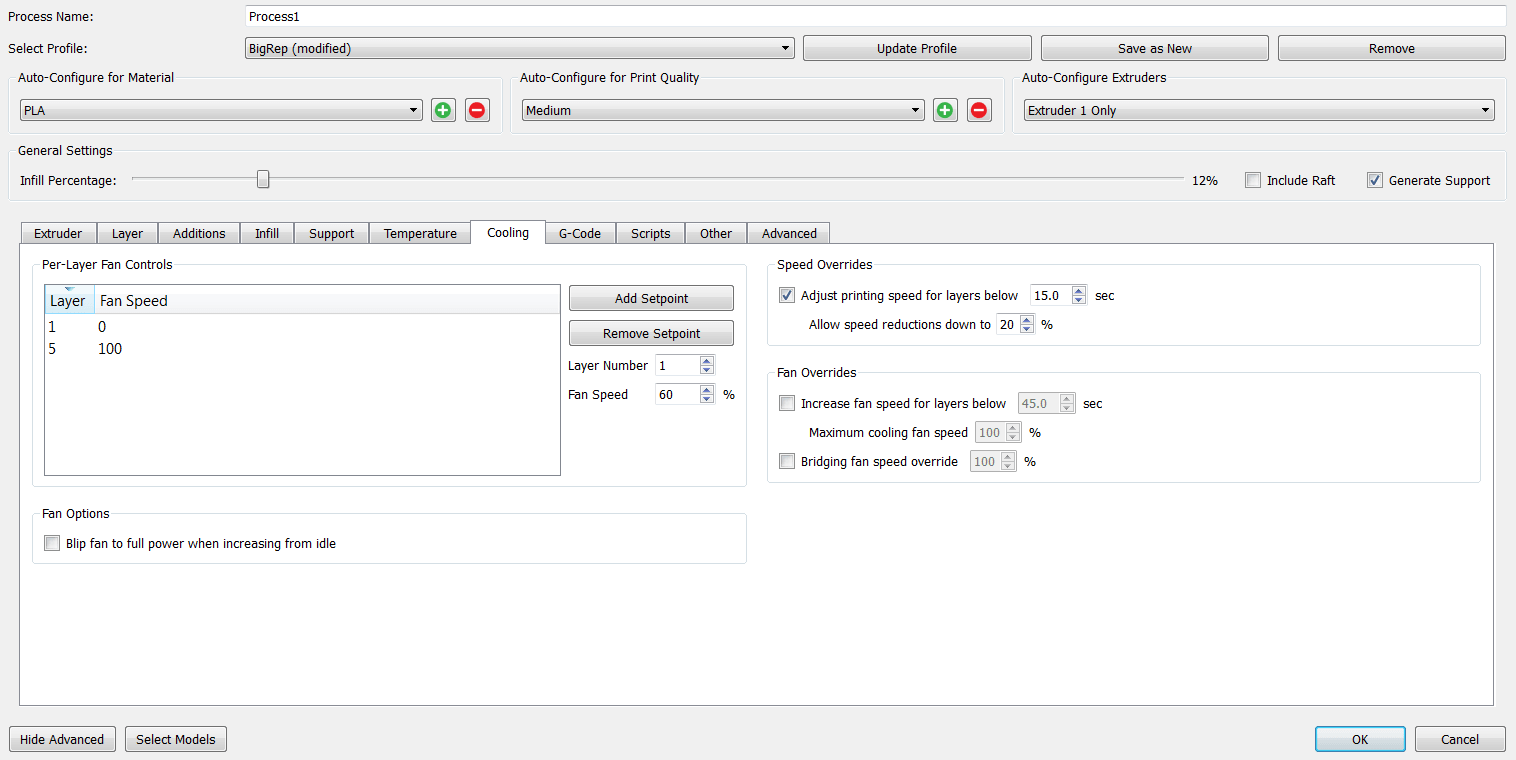
Cooling:
Other:

Advanced:
These are the changes that I made, the rest of the settings I just left by default.
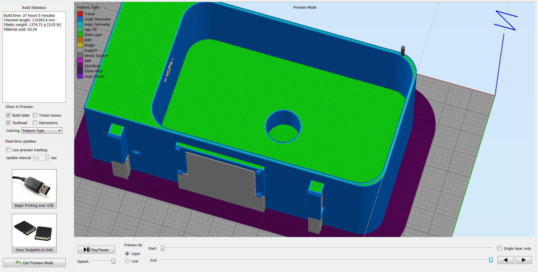
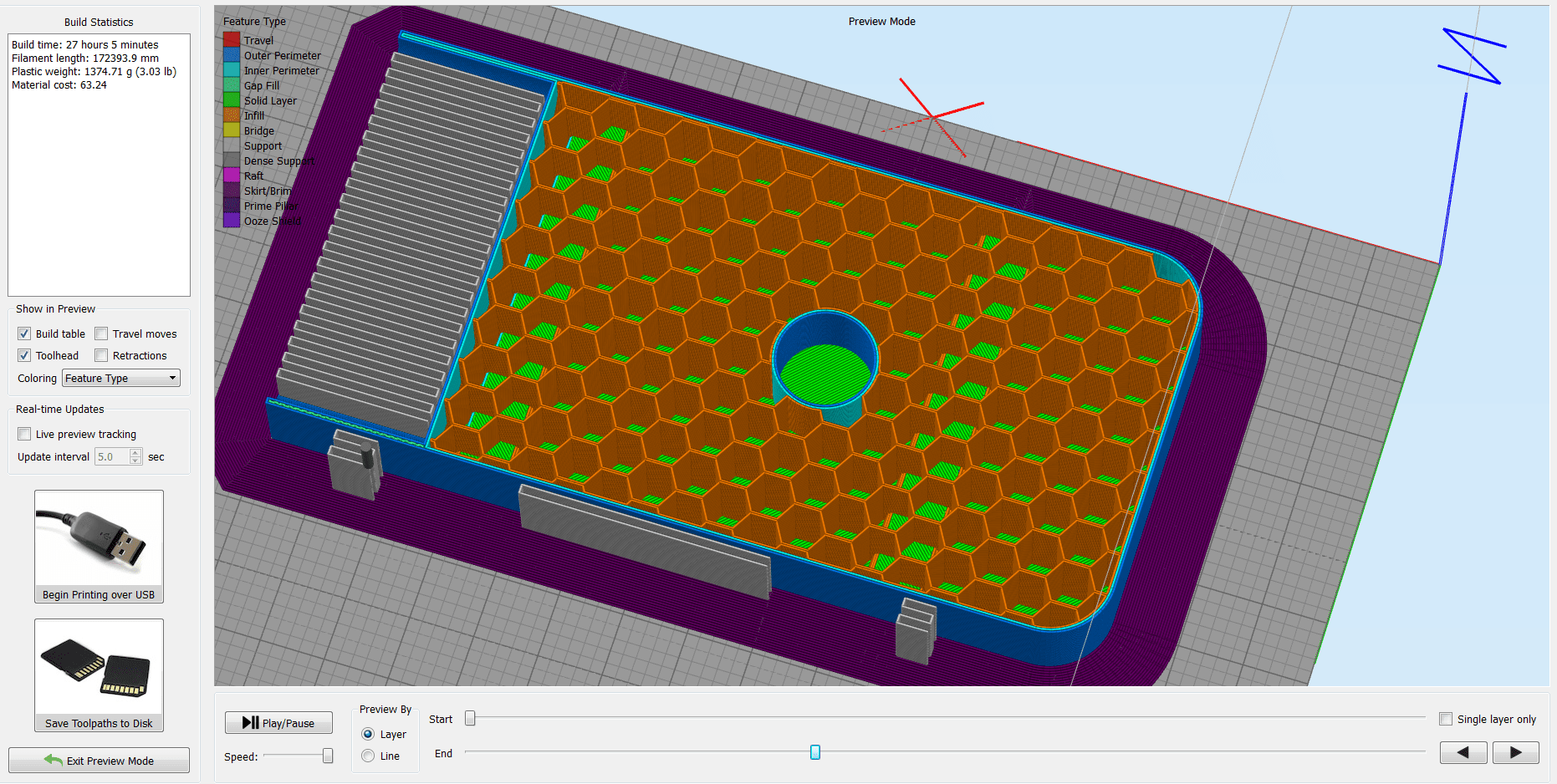
And then press on Prepare to Print . The software will generate the paths, and here we can check if everything is good, before sending the .gcode to the maschine.
Briefly about some of the printer's settings. I used Nozzle Temperature =205 deg.C , and the Bed Temperature =70 deg.C . After I positioned the X, Y, and Z axis , and double checked all the settings, I launched the job!
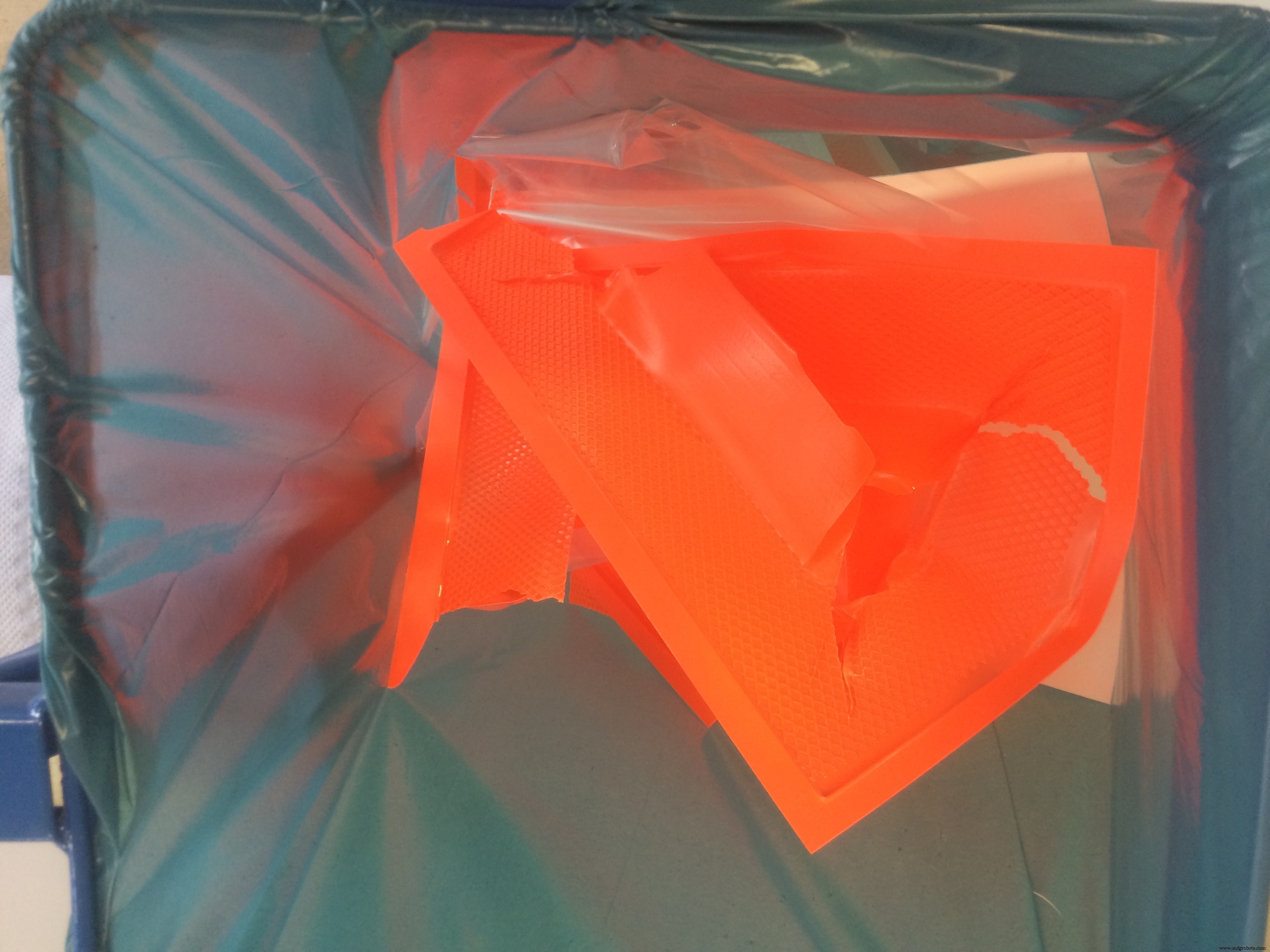
This is how the raw model looks like:
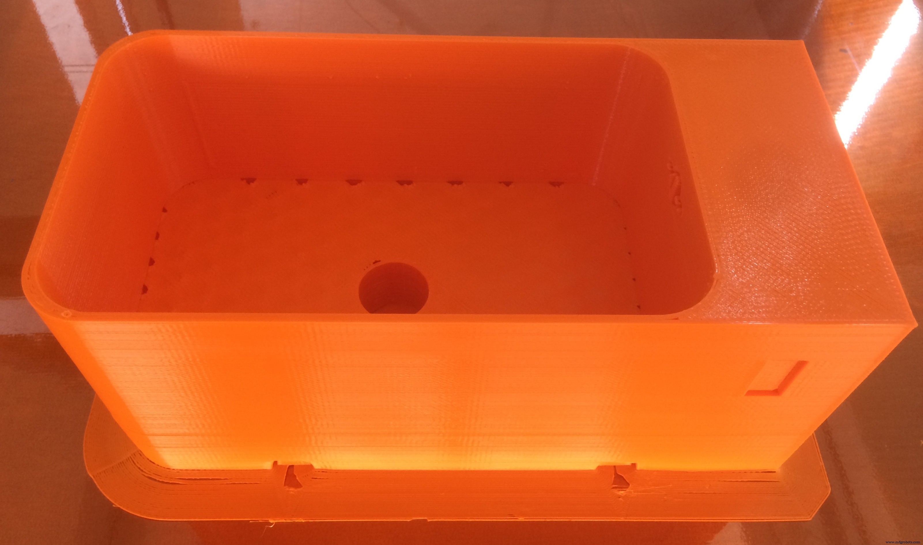
When I started removing the support and cleaning the model, I realized that this is a BIG pain in the ASS :D
As you can notice, the settings which I used are not really perfect, because the container has some big holes next to the edges. I had in my mind to waterproof it anyway, you can see how I did it in the Moulding &Casting section!
The next 3D printed part was the Net Pot . This is a cup which is designed to hold the seeds in the growing medium. More detailes about the first version of them you can see during my Computer-Aided Design week
This time I will improve the design a bit based on the observations that I made during the experimental stage. The main difference is the size of the empty space, which is increased a lot, to give an easier access for the fog to pass in, and for the roots to go through
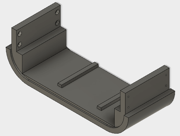
So I just modified the old design, and added one more thing!
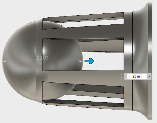
I made a slight fillet on the top part, to make the transition smoother. I also added a ball on the bottom, and used the Move command to move it a bit inside, and leave on the bottom around 2-3mm structure width
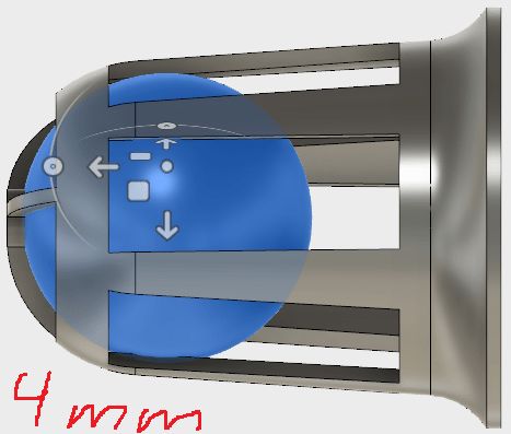
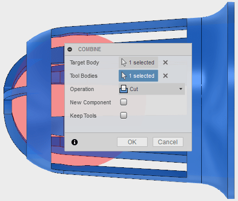
After I used the boolean substraction or Combine function, and I get this nice curviture at the bottom!
Now let's print it!
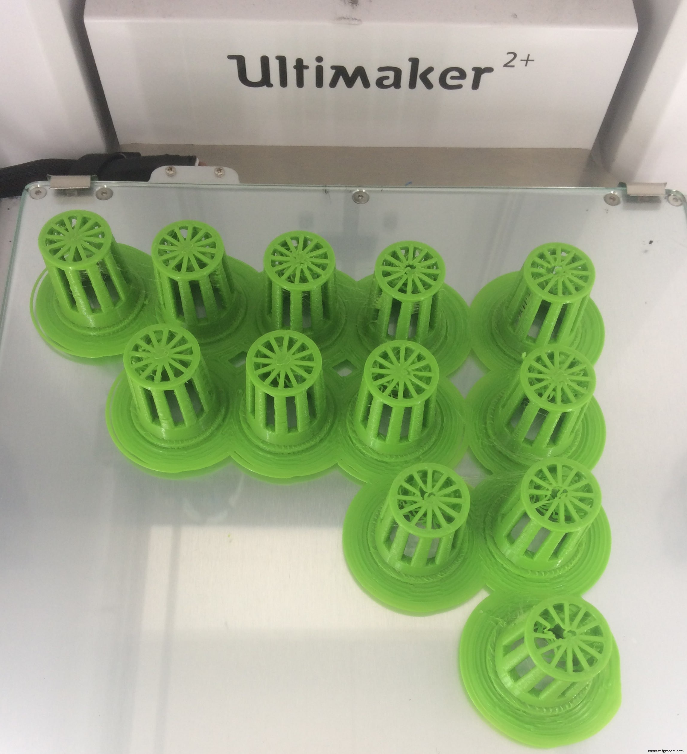
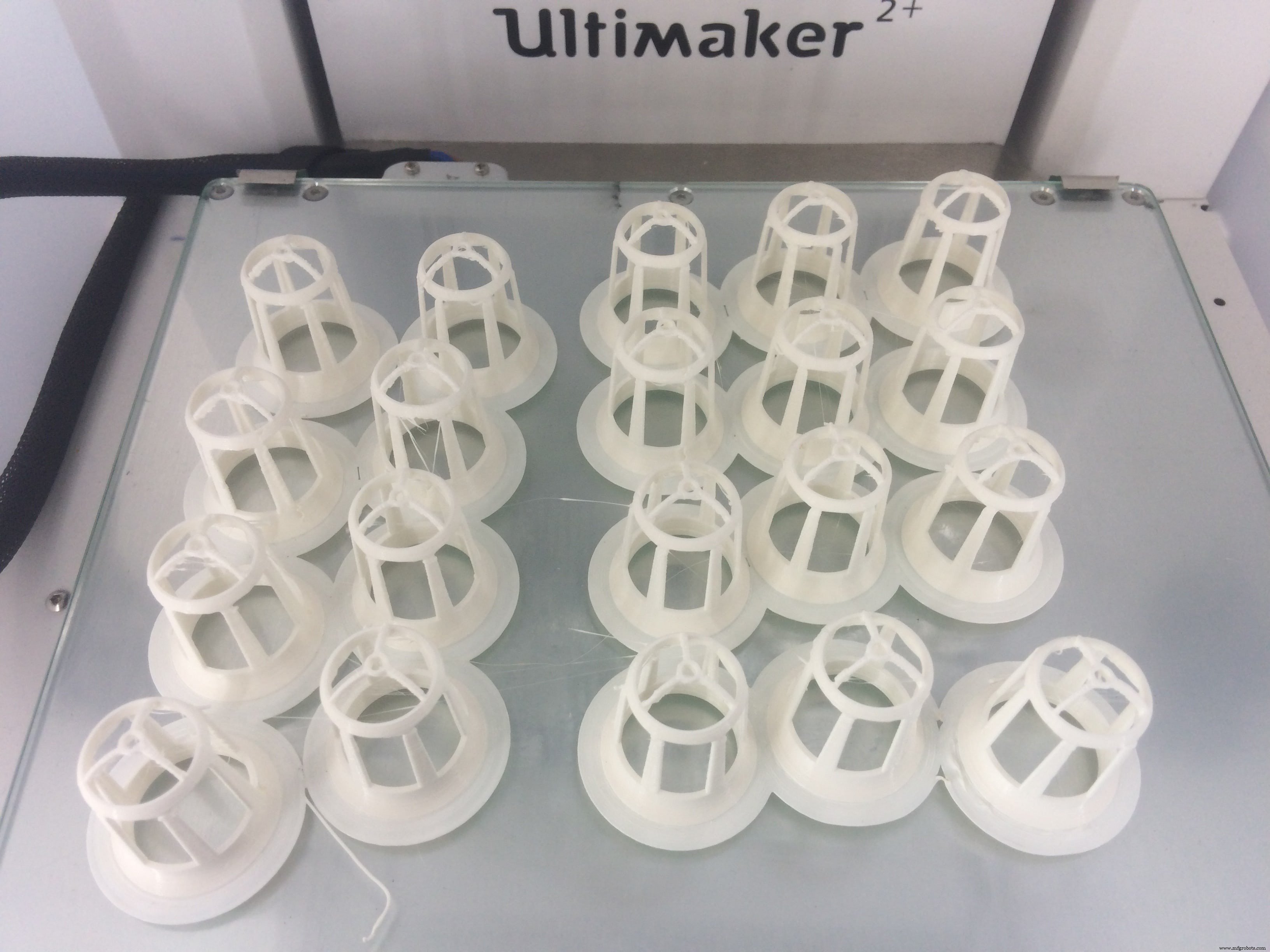
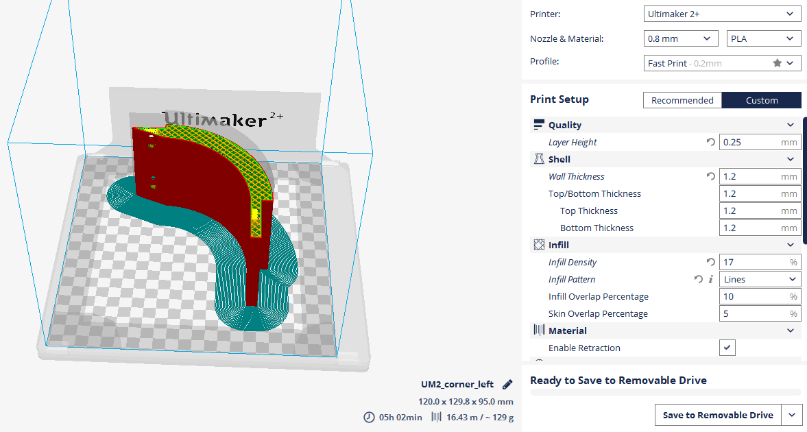
The 3D printer which I used is Ultimaker 2+ . To slice my 3D model, I will use, a very nice software, with an easy interface, and also functional. The material that I am using is PLA filament

After I import my .stl file, these are the settings that I am using:
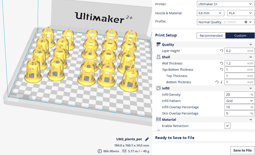
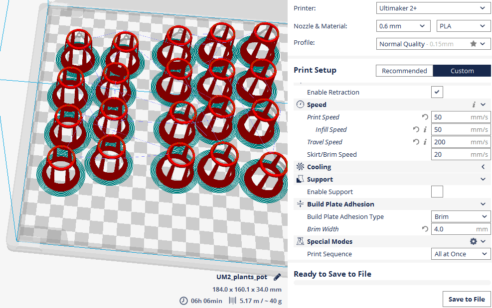
Here it is my little army :D
From the final design of the system, I decided to also 3D print the bottom part. Its a big piece, and I will use the BigRap as well for this.
I wouldn't say that there is anything new about this, because I used the same settings as I used for the water container , and more or less the rest is the same
Here is the preview of the print:
Another thing which I 3D printed are the rounded corners on the top side of the system. I used the Ultimaker for this, and used the following settings:
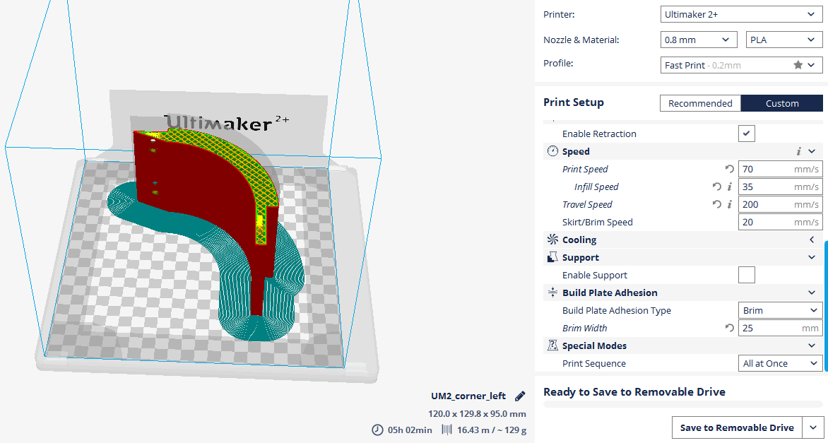
The trick here was to achieve maximum smoothness on the surface, and I think I got a pretty good result:

Download Files:
GIY System Design (.f3d)
Net Pot Design (.f3d)
2D Design &Laser Cutting
I used the Laser cutting technique to cut acrylic parts which will cover all the inside part of the system, and give it a finished look!
I actually did not design the parts again, I just exported the already created sketches from Fusion 360 as .dxf files . After I exported the file, I used to edit the design before importing it into the lasercut machine

This is how the sketch looks in Fusion360:
Looks like a big mess, but the good part is that everything is parametric! It looks messy because I had to align everything into the right position, and keep the stuff parametric in case I have to make a change later
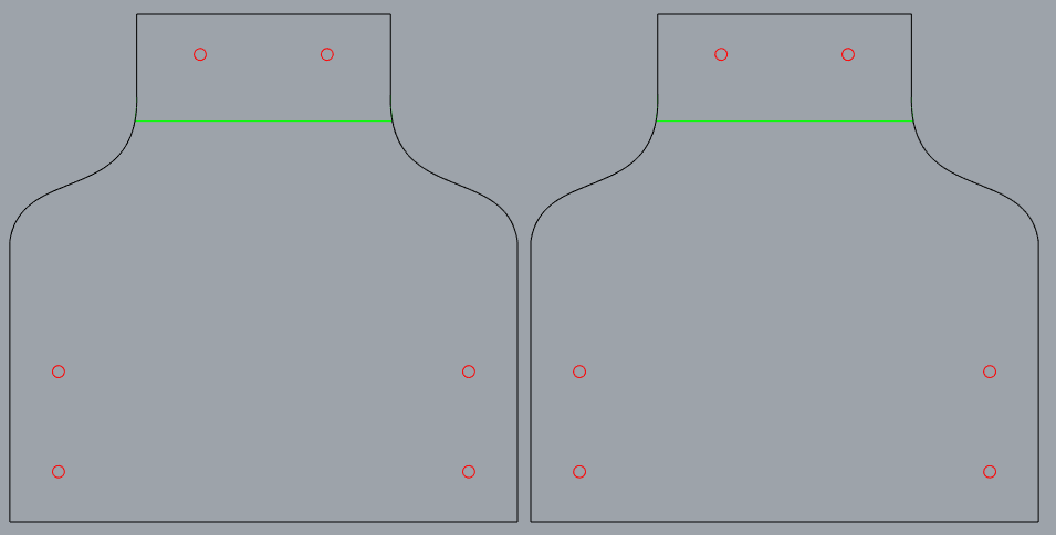
This is how the final sketch looks in Rhino before lasercutting:
I decided to use a green acrylic piece because it gives an organic look, and combines well with the green plants
For the front and the back cover, I decided to use white color. Its all about the taste, this is the way I see it, and this is how I like it.
The front and the back cover are very similar, have the same dimensions, except the inside cuts! The front cover has the hole for the LCD Display, here it is:

For the back cover, I want to make a hole to have access to power and program the board! This is how it looks:

Another lasercutted piece is on the top! I decided to use a transparent acrylic part, in order for the light to go through! I also designed some additional cuts, to decrease the weight, and give more space for the light to pass! I also measured the width of the RGB LED stripes, and will attach them in a way that there is enough room for the sunlight as well as artificial light!

I finished with the design, and now Let's Laser Cut!
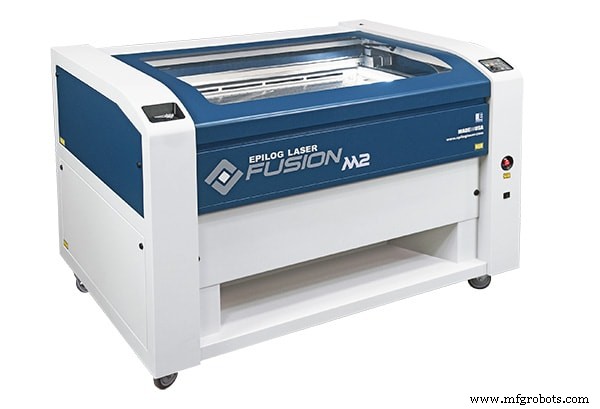
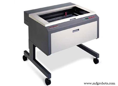
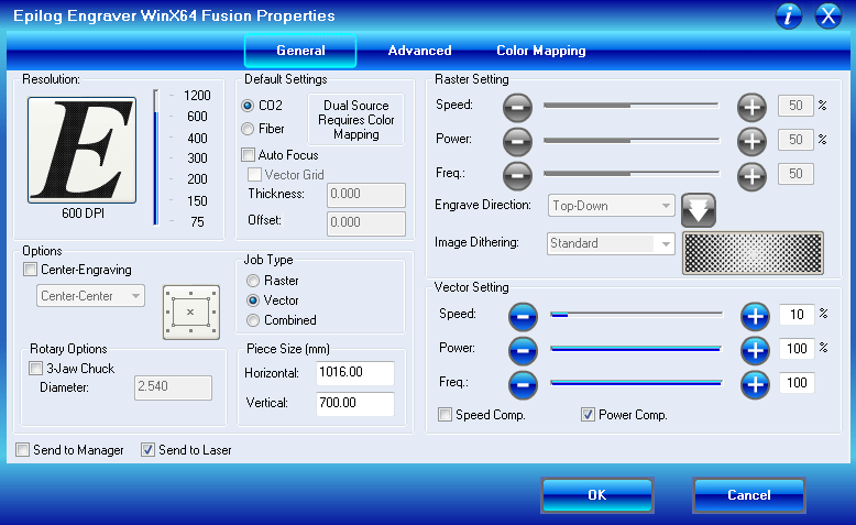
The Laser Cutter that we are using here in FabLab is Epilog Fusion 60Watt, a CO2 lasercutter with a working area of 1016 x 711 mm. It can cut and ingrave materials like wood, cardboard, acrylic or other engineered plastics.
Because I used the same material for all the pieces, plexiglass 5mm , I used the same settings for all of them!
Download Files:
Front / Back Cover (.dxf)
Plant Holder (.dxf)
LED Light Holder (.dxf)
CNC Milling
Because I wanted to integrate in my system all the skills and techniques that I learned, I also have a piece of structure to CNC mill. I did not design it again, but I exported the .dxf file from Fusion360 sketch!
To cut my design, I will be using the big CNC monster.
A CNC (computer numerically controlled) is a machine that uses a cutting bit that rotates at a very high speed to remove material from a part.
The machine reads a pre‐programed computer file telling it where and how to cut, usually .GCode 文件。 A cutting bit is rotated at a very high RPM by a spindle motor, which can move the bit up and down. This mechanism is moved left, right, front, and back by a cross arm. The machine is therefore known as a three‐axis router because it can move on the X, Y &Z axis. The machine can do two dimensional cutouts and etching, as well as three‐dimensional relief work.
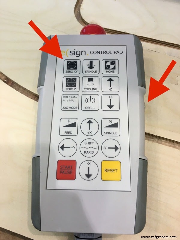
In FabLab Kamp-Lintfort we have a CNC portal milling machine by e(sign:Easy Worker MasterPro 2513.

It’s working area is 2600 x 1400 x 300mm and it comes with a vacuum table. We primarily use it for wood milling but with its HSD Spindel (3.9KW; 24.000U/min) it is also capable to mill metals easily.
The material which I will be using is 18mm Plywood
At first, I place the wood sheet on the CNC bed, and after I aligned it, switch on the vacuum. After I exported the .dxf file, I used to edit the design before importing it into the machine CAM software.
First, I have to HOME the machine!
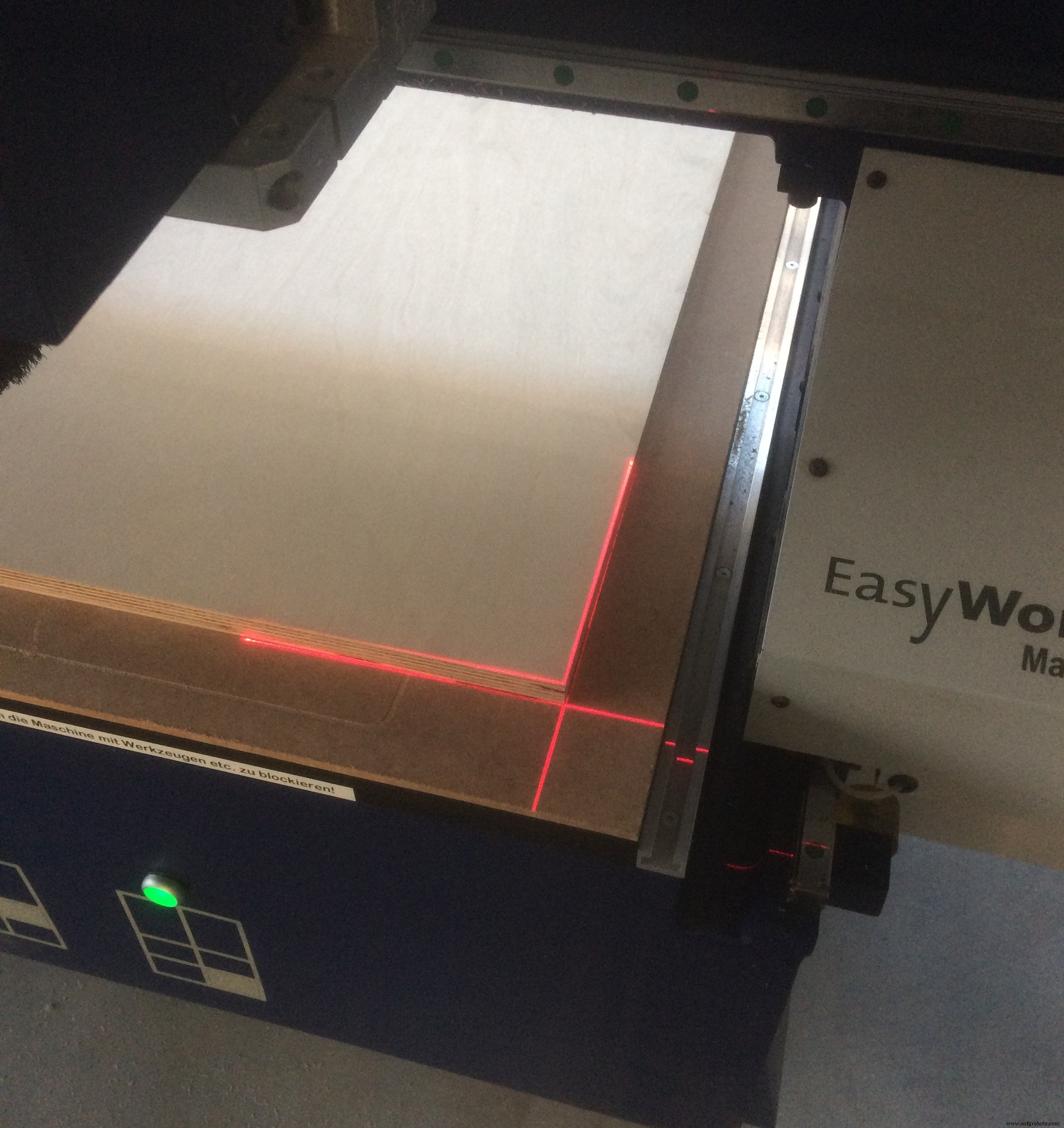
To set the X, Y and Z Zero Positions, I home the machine by pressing the home button in the software (or on the remote control).
At first, I can set my zero X and Y roughly aligned to one of the corners of the bed. We also tried to use the laser for this, but all the time when simulating the process, it was showing collisions, because the zero was going out of the working area
Now I have to find the Z axis, which I do using the special tool which comes with the machine:
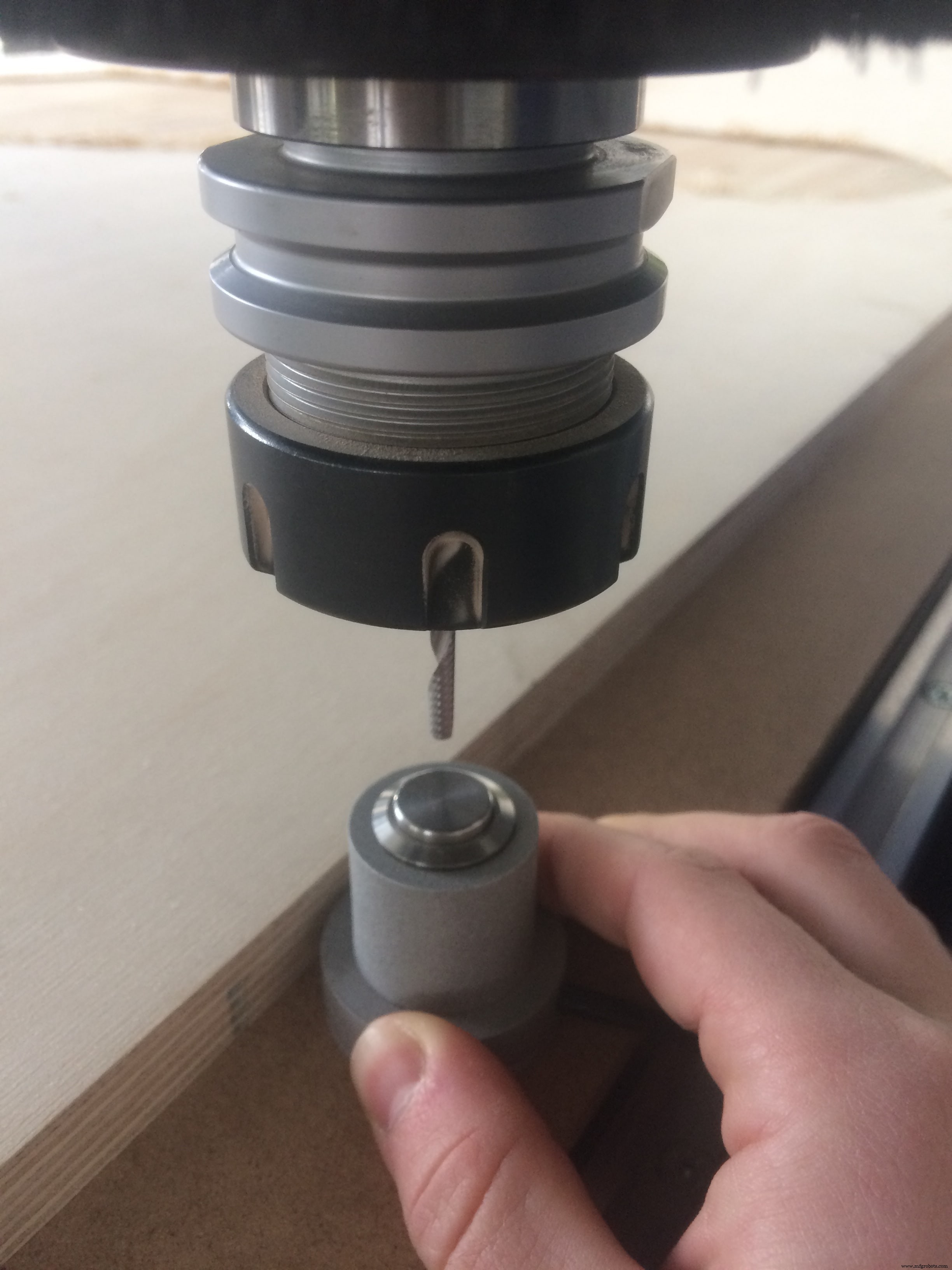
Important thing is to place it on the bed of the machine!
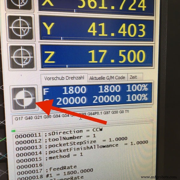
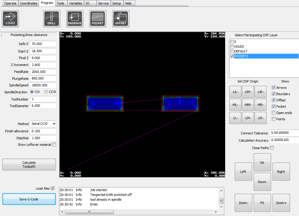
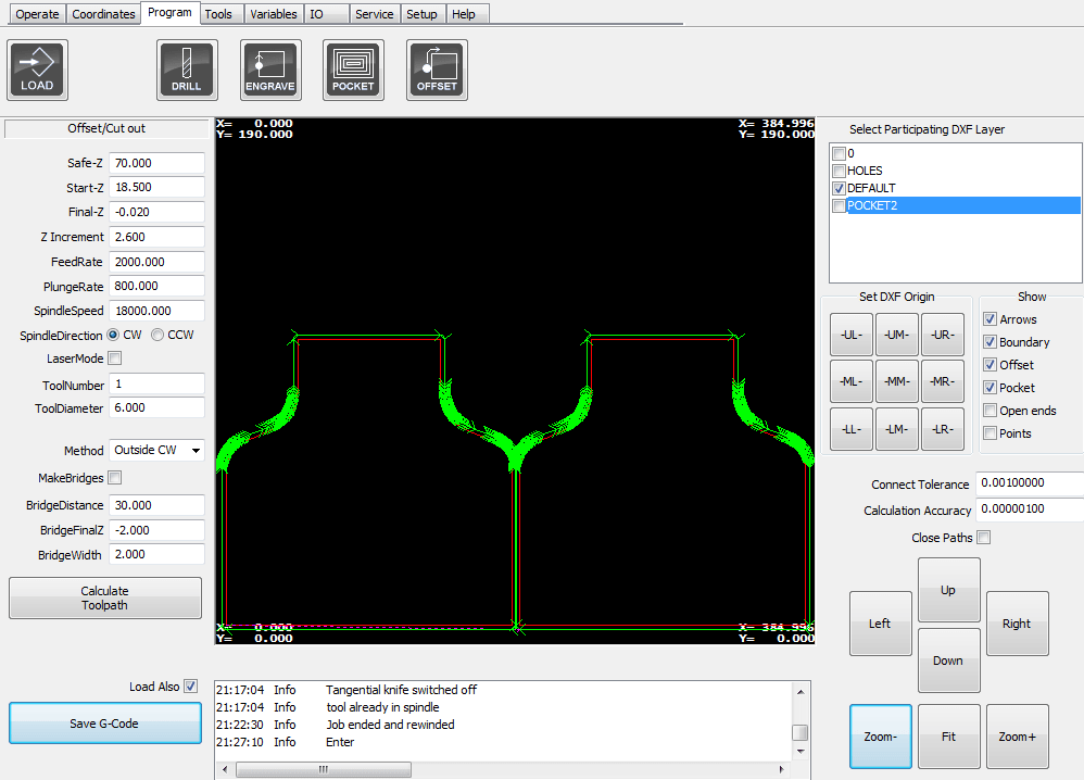
Now I can launch the first job, which is making the engraving. These are the settings which I used:
I press Calculate Toolpath to simulate the job and make sure that there are no collisions! After I save the .GCode , and launch the job, I get this window:
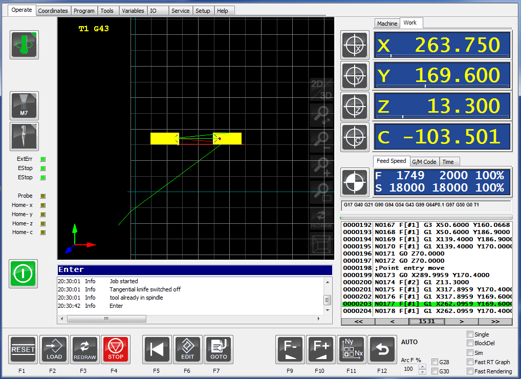
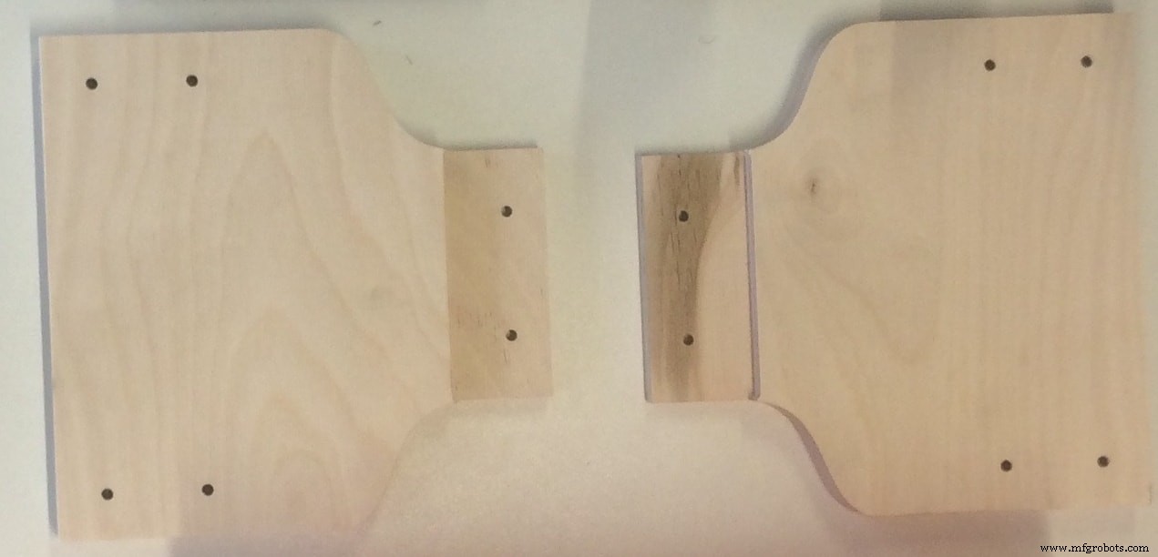
Now I can launch the outside cut:

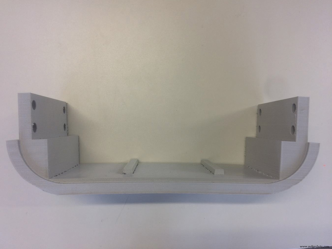
This is what I get after the job is done:
Another piece which I had to mill is used for the Moulding &Casting section!
I prepared the mould to waterproof my water container. Here is the design:

There is nothing new about this. I used exactly the same settings as above. The only thing is the material thickness was 10mm wood , and I had to cut 7 pieces, to glue them together later and prepare my mould!
Download Files:
Structure Walls (.dxf)
Mould (.dxf)
Moulding &Casting
I used this technique in order to prepare a water container, to waterproof my existing container! I see it as a thin layer of material (a smaller container) which can be easily removable!
This is the result from the previous section CNC Milling
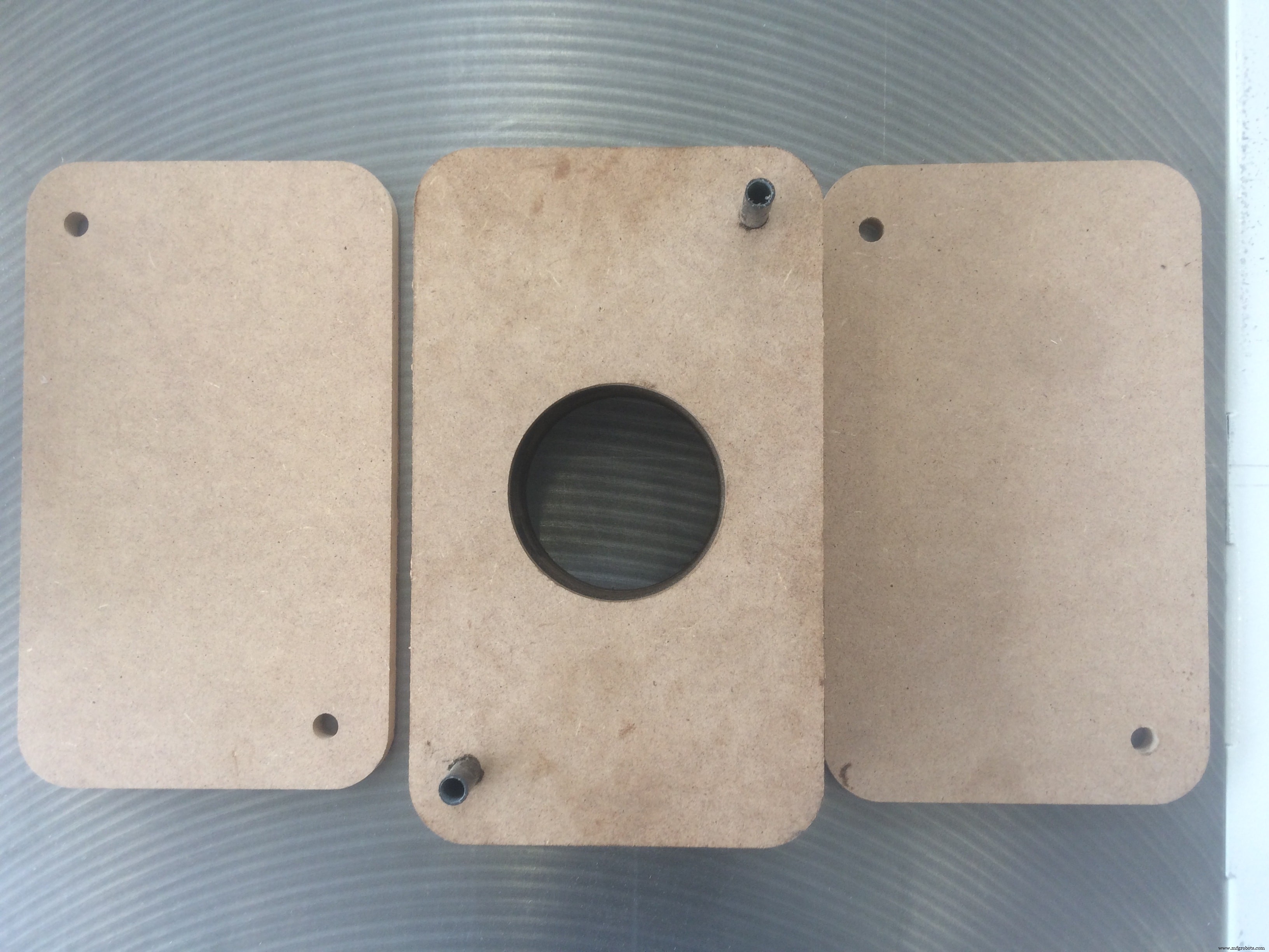
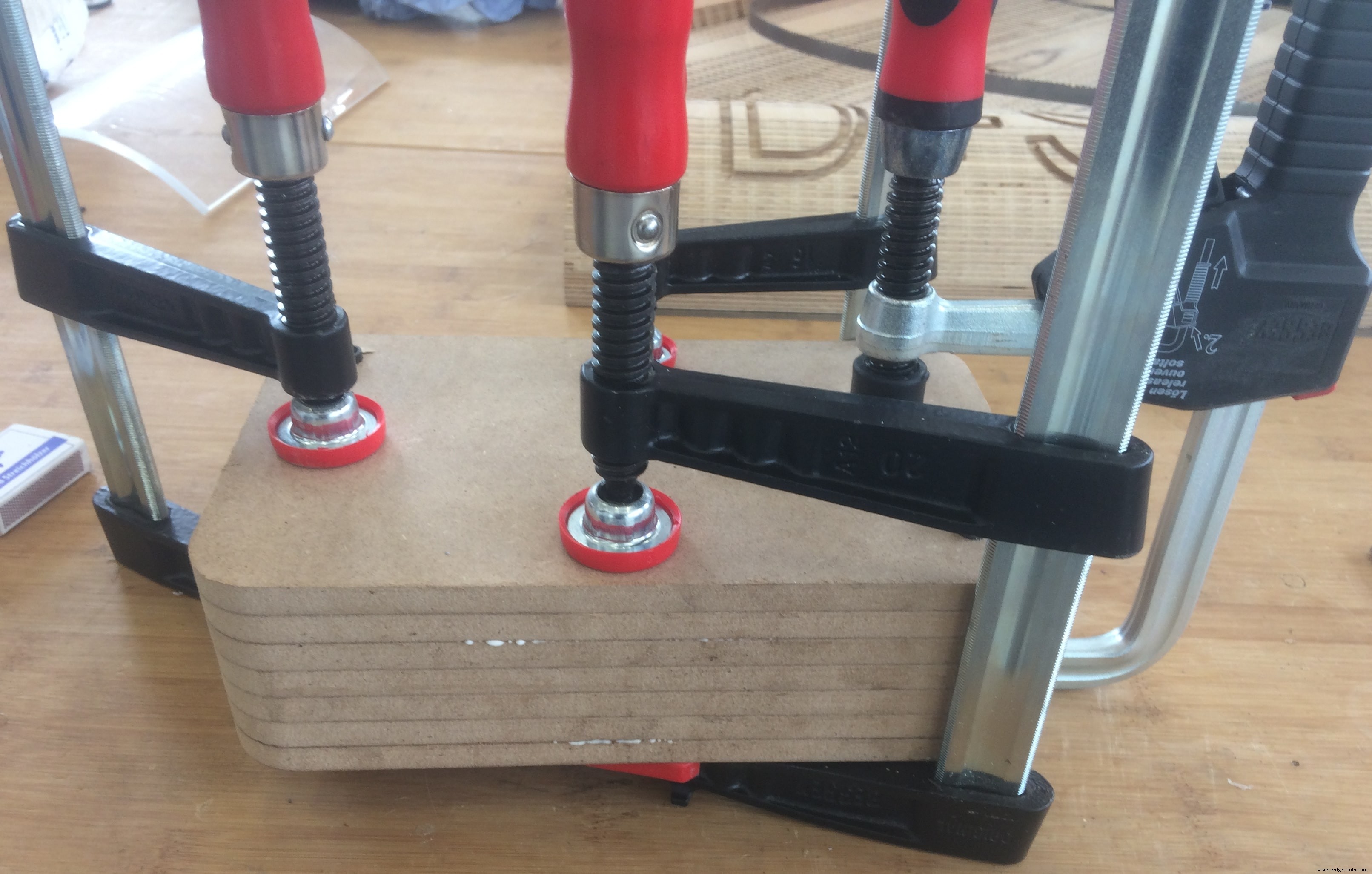
I cut 7 identical pieces, and aligned them using the reference holes! I also cut a big hole in the middle of 5 bottom pieces , in order to place the air pump inside, and easily remove the cast later.
After I glued all the pieces together, and fixed them, this is how it looks:
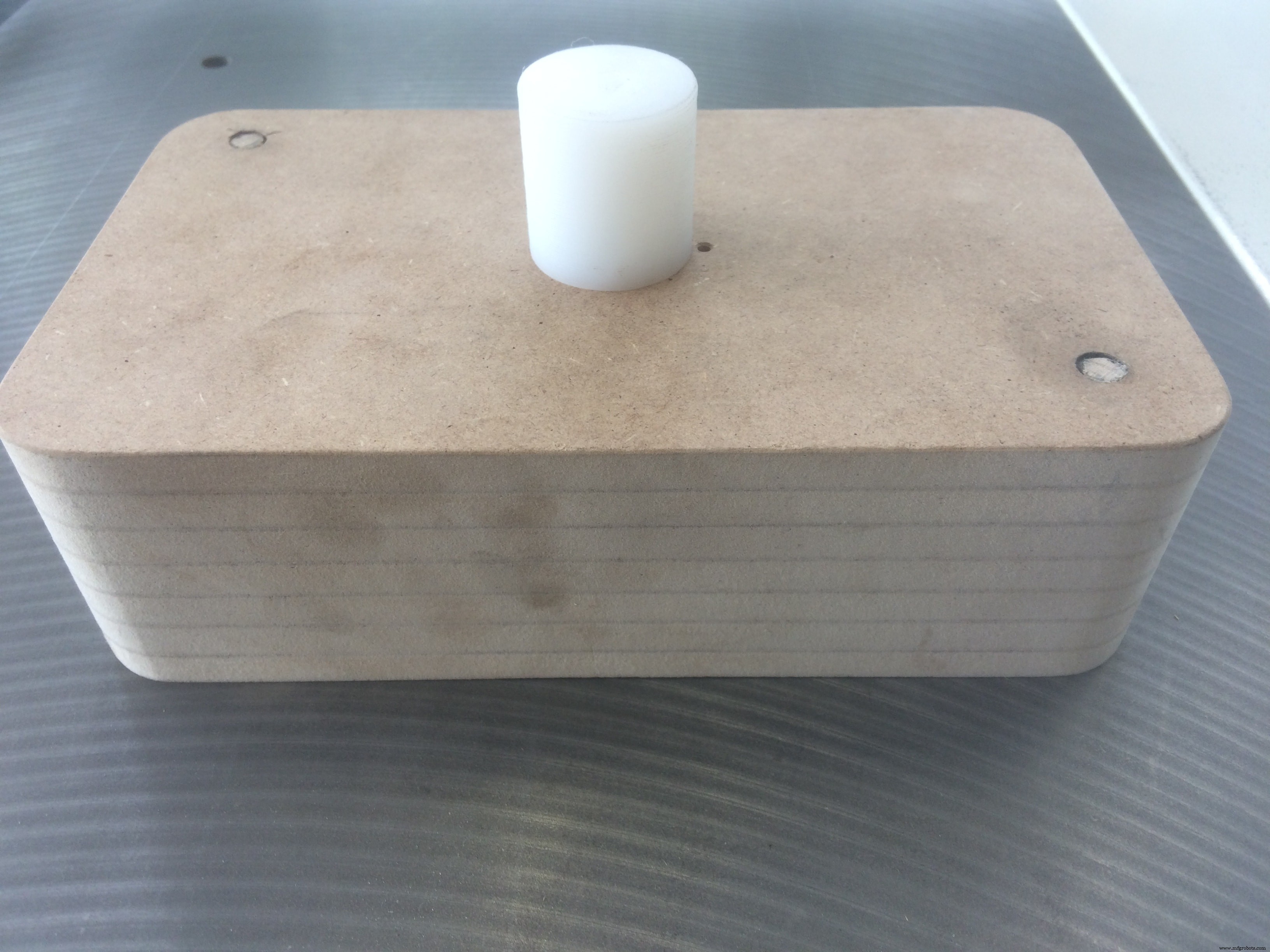
While waiting for the glue to dry out, I prepared a little plastic "thing" (do not know how to call it :D) for the pump. The idea is to be able to screw it on my mould, and remove it whenever I want!
When the mould is ready, this is how it looks:
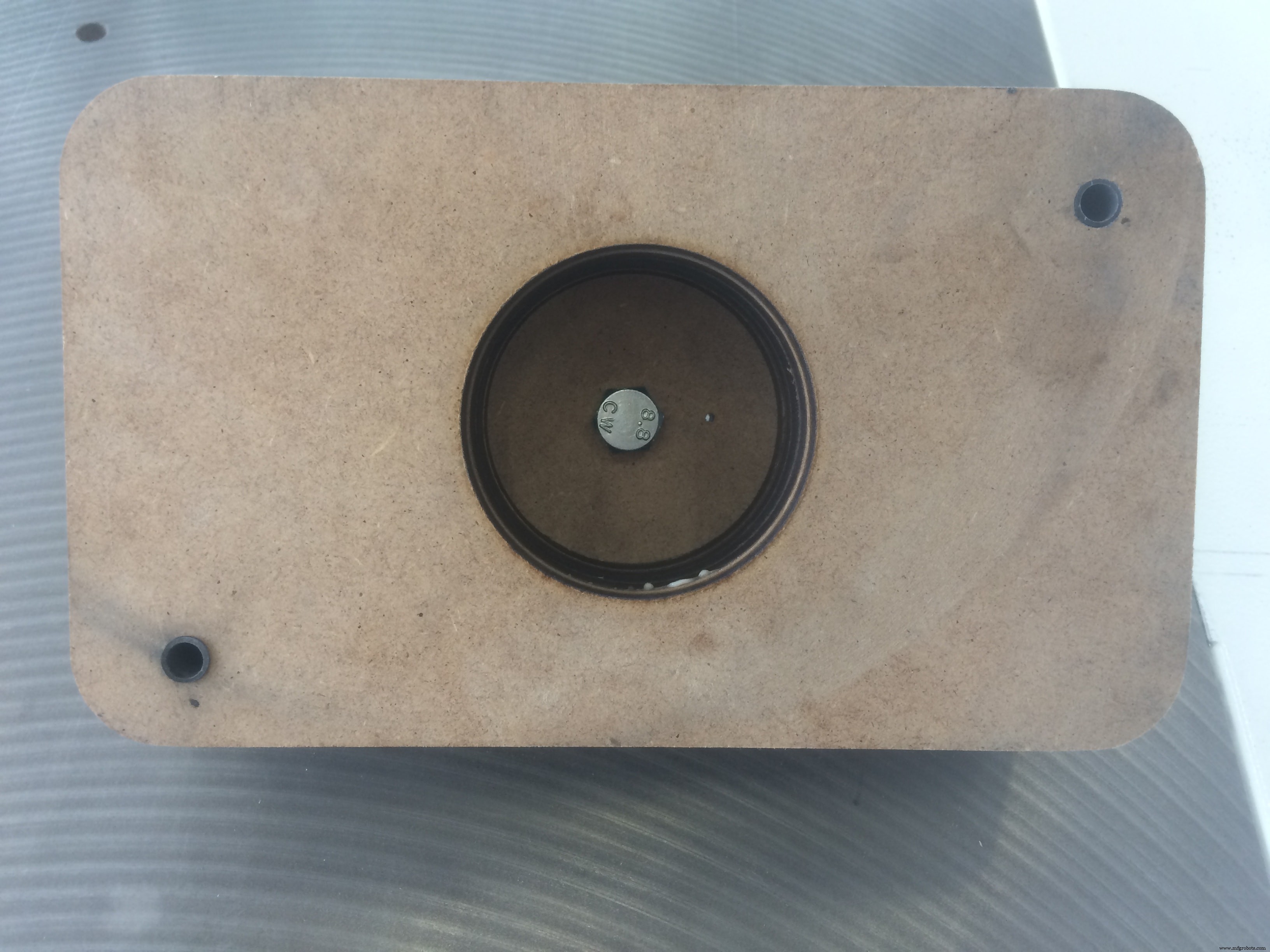
And the back side:
I am ready to vacuum cast!
I used a vacuum machine available in our FabLab Kamp-Lintfort called Formech – Manual Vacuum Forming Machine
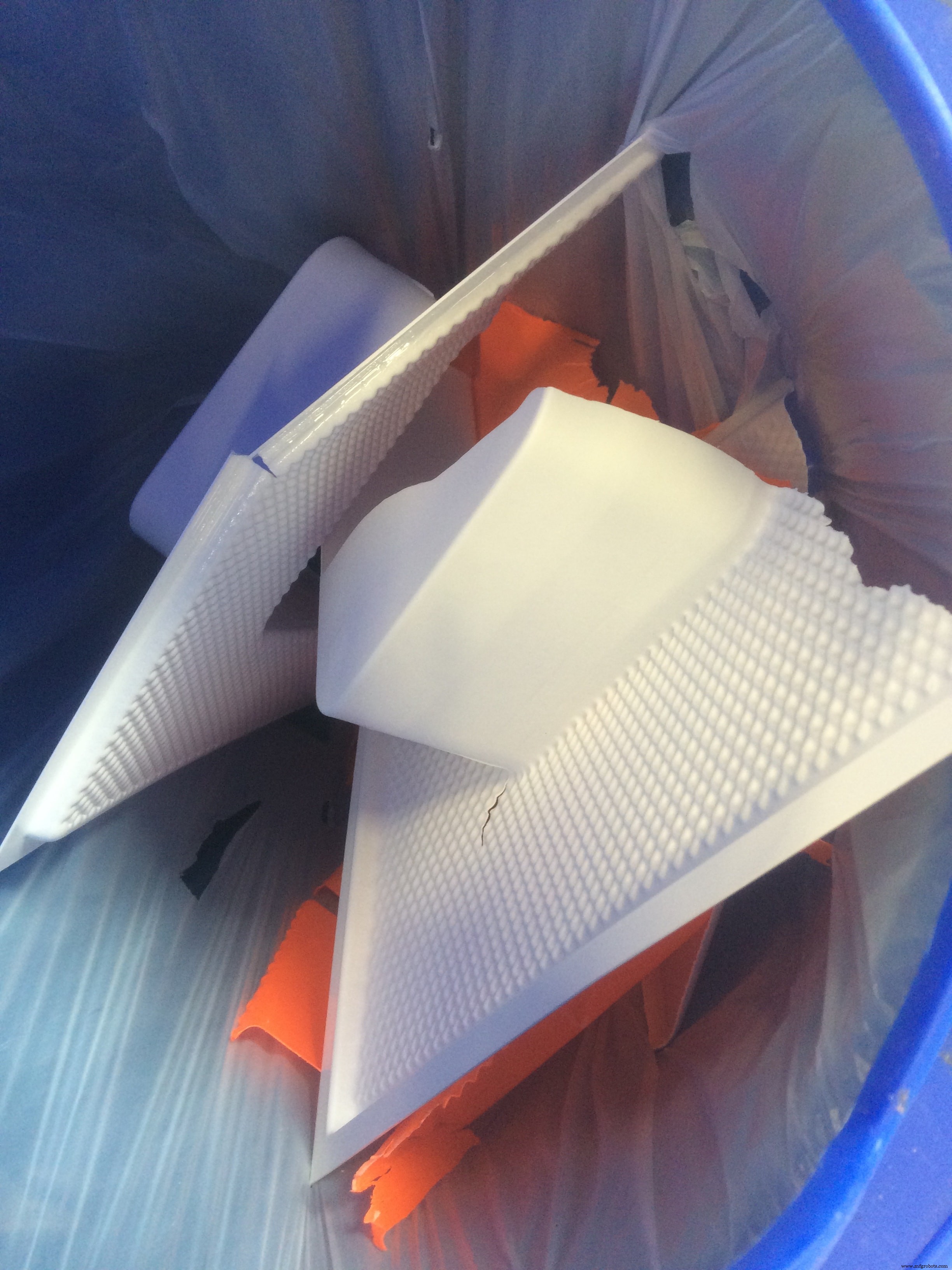
The thing is that I tried to do it many times, and all the time I could not remove the mould without breaking the cast! After several hours of trials, I came up with a solution! First, I vacuum casted one thin layer of material, and without removing it, I will cast the actual container on top of it. The first thin layer is slippery, and If I spray it with silicon, it will allow me to remove the mould way easier
After I let the silicon to dry a bit, I can cast the actual layer!
And here we are!!!
A hero shot for those who may thing that it was easy
Putting All Together
Now, let's put everything together! I will start by assembling the structure. Put next to me all the necessary tools:
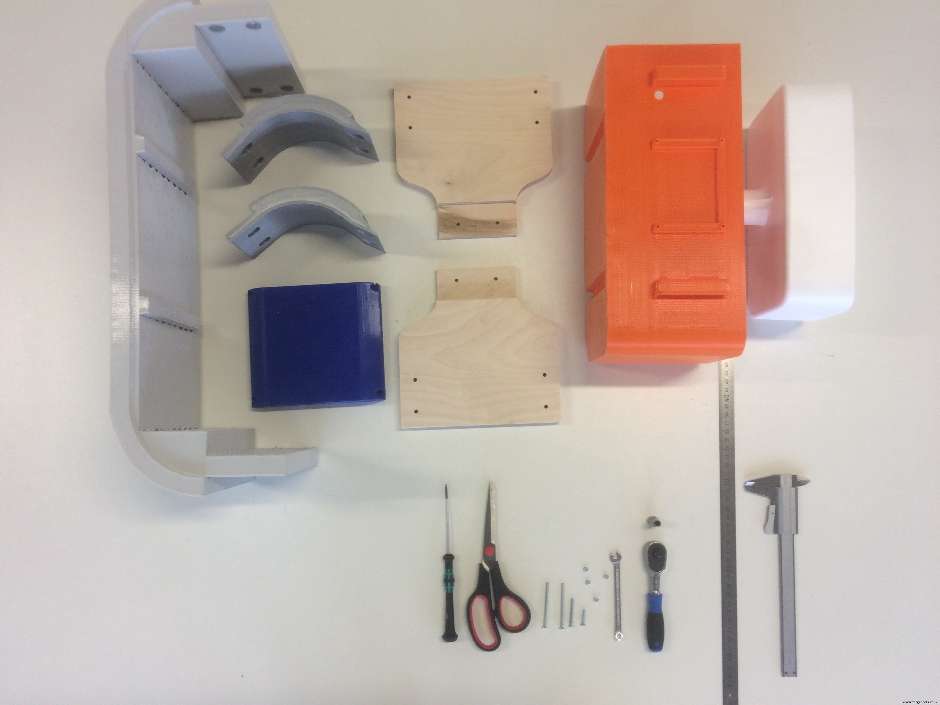
A short animation of the process:
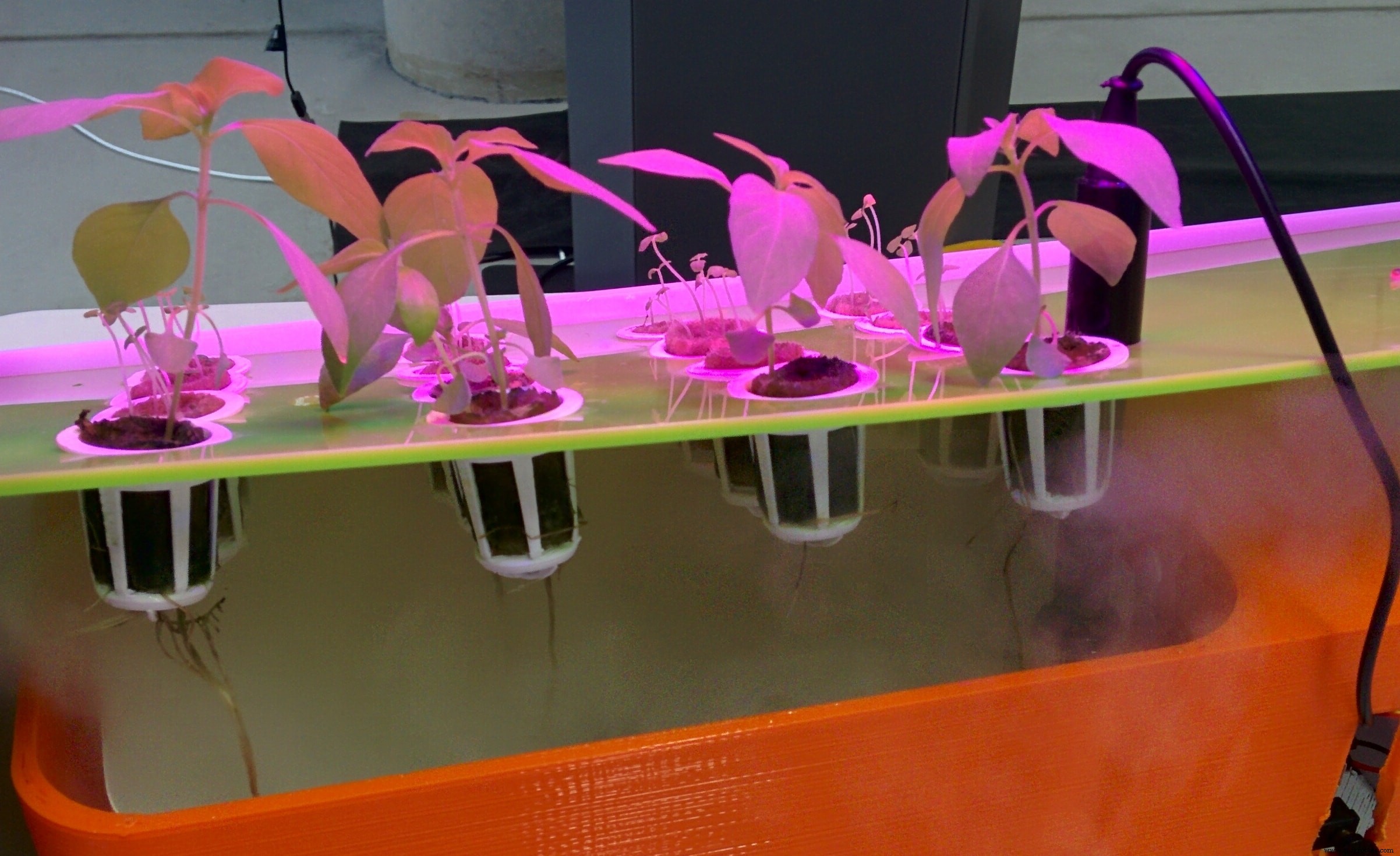
To assemble the lights, I cut the RGB LED stripes into 4 pieces (I measured the length in advance), and soldered them accordingly!
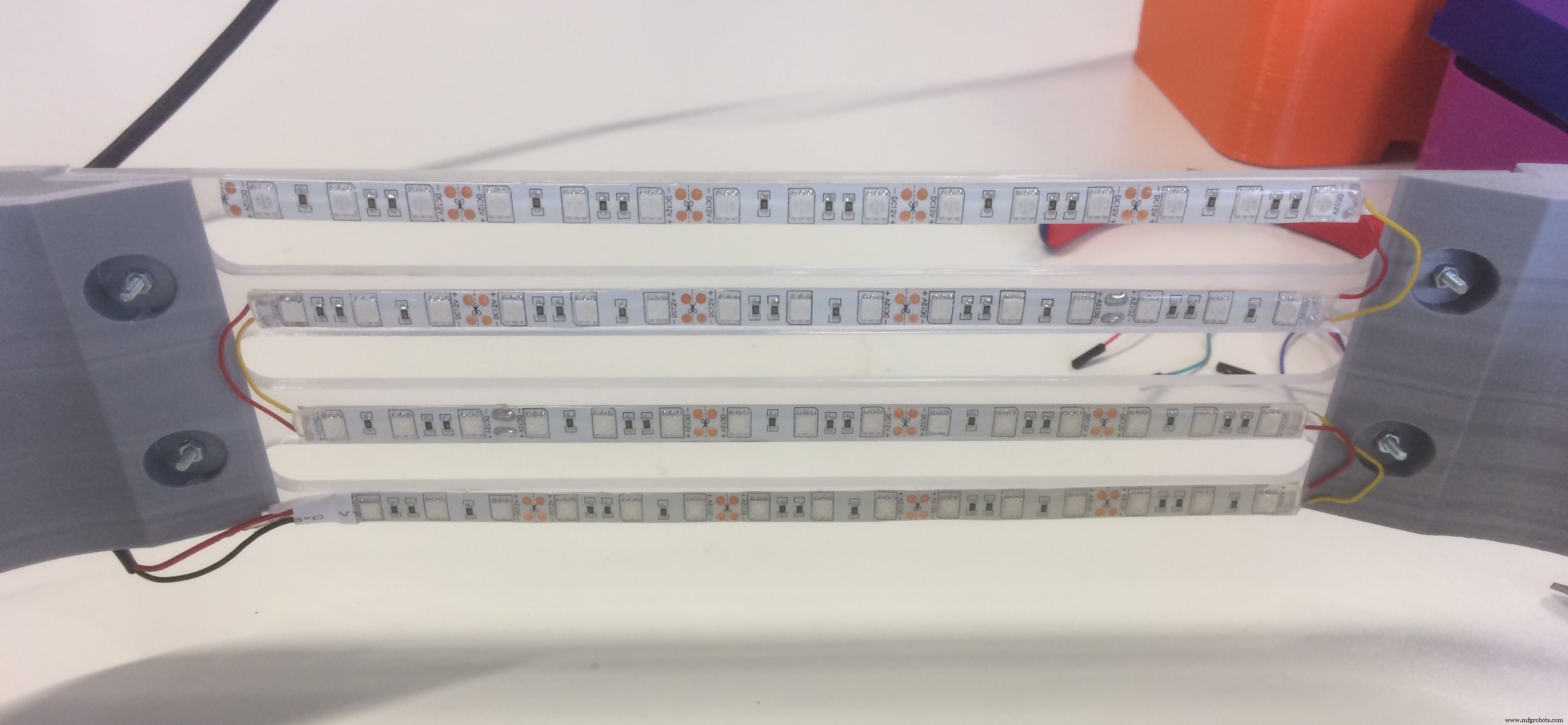
After I connected all the sensors, and managed the wiring, I fixed the board in the electronics section
And here it is the system!!! Everything assembled, nice looking growing system GIY
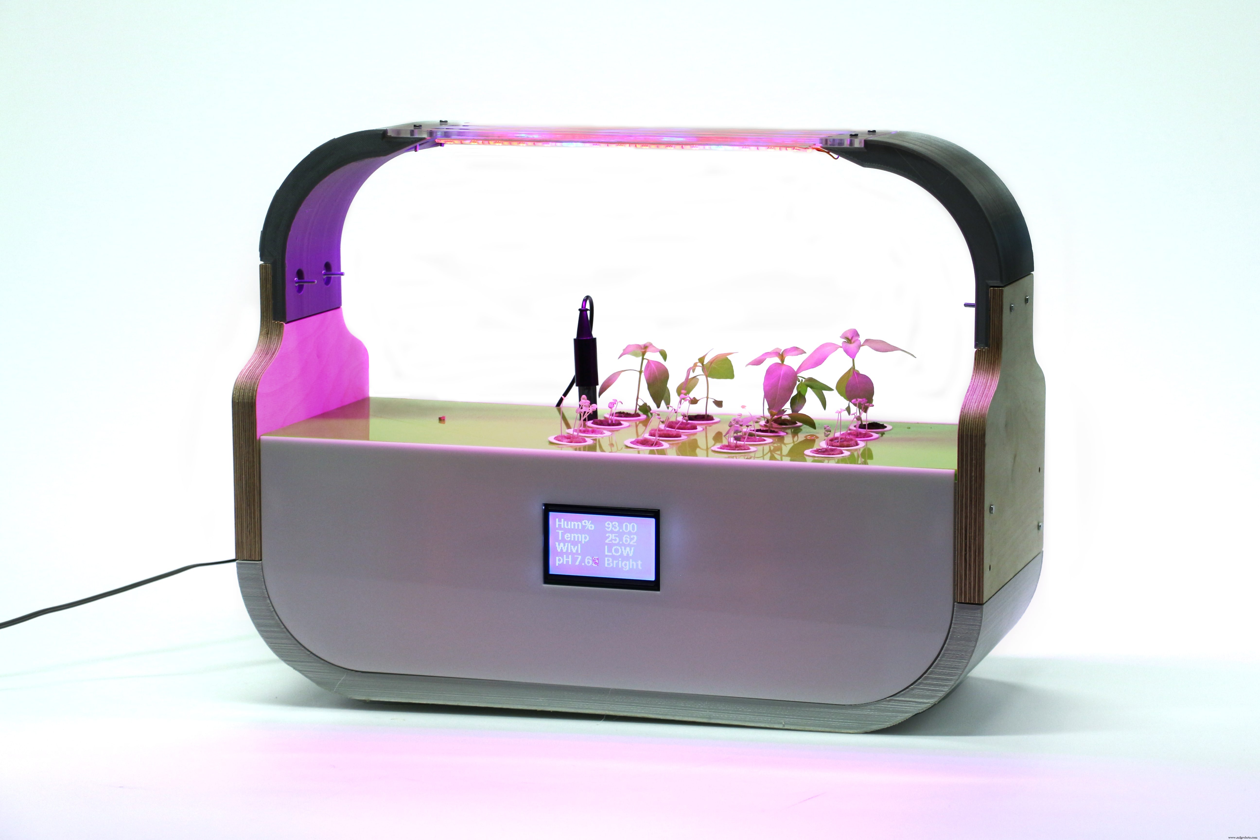
A HERO shot during the working process!
Final Presentation Video
© 2017 Albot Dima. All rights reserved | Albot.Dumitru@hsrw.org
This work is licensed under a Creative Commons Attribution-NonCommercial-ShareAlike 4.0 International License.

For more details about project, please visit official source:
http://archive.fabacademy.org/2017/fablabkamplintfort/students/396/final.html
代码
- GIY Board - CODE
- GIY BOARD - LCD + LIGHT CODE
GIY Board - CODEArduino
#include "dht.h"#include "U8glib.h"#include#include #define DHT11_PIN 2 // what digital pin we're connected to#define ONE_WIRE_BUS 3#define WATER_LEVEL A4#define LDR_PIN A3#define PH_PIN A5#define GROW_LIGHT 10#define FOG_PUMP 13int waterLevel;int LightLevel;int pH;dht DHT;OneWire oneWire(ONE_WIRE_BUS); DallasTemperature waterTemp(&oneWire);U8GLIB_ST7920_128X64 u8g(4, 12, 6, U8G_PIN_NONE);const unsigned char logo [] PROGMEM ={0xFF, 0xFF, 0xFF, 0xFE, 0x7F, 0xFF, 0xFF, 0xFF, 0x00, 0x00, 0x00, 0x00, 0x00, 0x00, 0x00, 0x00,0xFF, 0xFF, 0xFF, 0x00, 0x00, 0xFF, 0xFF, 0xFF, 0x00, 0x00, 0x00, 0x00, 0x00, 0x00, 0x00, 0x00,0xFF, 0xFF, 0xF8, 0x00, 0x00, 0x1F, 0xFF, 0xFF, 0x00, 0x00, 0x00, 0x00, 0x00, 0x00, 0x00, 0x00,0xFF, 0xFF, 0xC0, 0x00, 0x00, 0x03, 0xFF, 0xFF, 0x00, 0x00, 0x00, 0x00, 0x00, 0x00, 0x00, 0x00,0xFF, 0xFF, 0x00, 0x00, 0x00, 0x00, 0xFF, 0xFF, 0x00, 0x00, 0x00, 0x00, 0x00, 0x00, 0x00, 0x00,0xFF, 0xFE, 0x00, 0x03, 0xC0, 0x00, 0x7F, 0xFF, 0x00, 0x00, 0x00, 0x00, 0x00, 0x00, 0x00, 0x00,0xFF, 0xF8, 0x00, 0x07, 0xE0, 0x00, 0x3F, 0xFF, 0x00, 0x00, 0x00, 0x00, 0x00, 0x00, 0x00, 0x00,0xFF, 0xF0, 0x00, 0x1F, 0xF8, 0x00, 0x0F, 0xFF, 0x00, 0x00, 0x00, 0x00, 0x00, 0x00, 0x00, 0x00,0xFF, 0xE0, 0x00, 0x3F, 0xFE, 0x00, 0x07, 0xFF, 0x00, 0x00, 0x00, 0x00, 0x00, 0x00, 0x00, 0x00,0xFF, 0xC0, 0x00, 0x18, 0x1F, 0x00, 0x03, 0xFF, 0x00, 0x00, 0x00, 0x00, 0x00, 0x00, 0x00, 0x00,0xFF, 0x80, 0x00, 0x00, 0x03, 0xC0, 0x01, 0xFF, 0x00, 0x00, 0x00, 0x00, 0x00, 0x00, 0x00, 0x00,0xFF, 0x00, 0x00, 0x00, 0x00, 0xF0, 0x00, 0xFF, 0x00, 0x00, 0x00, 0x00, 0x00, 0x00, 0x00, 0x00,0xFE, 0x00, 0x00, 0x00, 0x00, 0x7C, 0x00, 0x7F, 0x00, 0x00, 0x00, 0x00, 0x00, 0x00, 0x00, 0x00,0xFC, 0x00, 0x00, 0x00, 0x00, 0x3E, 0x00, 0x7F, 0x00, 0x00, 0x00, 0x00, 0x00, 0x00, 0x00, 0x00,0xFC, 0x03, 0x80, 0x00, 0x00, 0x3F, 0x80, 0x3F, 0x00, 0x00, 0x00, 0x00, 0x00, 0x00, 0x00, 0x00,0xF8, 0x07, 0xE0, 0x00, 0x00, 0x1F, 0xE0, 0x1F, 0x00, 0x00, 0x00, 0x00, 0x00, 0x00, 0x00, 0x00,0xFC, 0x1F, 0xF0, 0x00, 0x00, 0x1F, 0xF0, 0x1F, 0x00, 0x00, 0x00, 0x00, 0x00, 0x00, 0x00, 0x00,0xF0, 0x3F, 0xF0, 0x00, 0x00, 0x1F, 0xFC, 0x0F, 0x00, 0x00, 0x00, 0x00, 0x00, 0x00, 0x00, 0x00,0xF0, 0xFF, 0xF0, 0x00, 0x00, 0x1F, 0xFF, 0x0F, 0x00, 0x00, 0x00, 0x00, 0x00, 0x00, 0x00, 0x00,0xE0, 0xFF, 0xF0, 0x00, 0x00, 0x3F, 0xFF, 0x07, 0x00, 0x00, 0x00, 0x00, 0x00, 0x00, 0x00, 0x00,0xE0, 0xFF, 0xF0, 0x00, 0x00, 0x3F, 0xFF, 0x07, 0x00, 0x00, 0x00, 0x00, 0x00, 0x00, 0x00, 0x00,0xC0, 0xFF, 0xF8, 0x00, 0x00, 0x7F, 0xFF, 0x03, 0x00, 0x00, 0x00, 0x00, 0x00, 0x00, 0x00, 0x00,0xC0, 0xFF, 0xFC, 0x00, 0x00, 0xFF, 0xFF, 0x03, 0x00, 0x00, 0x00, 0x00, 0x00, 0x00, 0x00, 0x00,0xC0, 0xFF, 0xFF, 0x00, 0x01, 0xFF, 0xFF, 0x03, 0x00, 0x00, 0x00, 0x00, 0x00, 0x00, 0x00, 0x00,0x80, 0xFF, 0xFF, 0xC0, 0x07, 0xFF, 0xFF, 0x01, 0x00, 0x00, 0x00, 0x00, 0x00, 0x00, 0x00, 0x00,0x80, 0xFF, 0xFF, 0xFF, 0xFF, 0xFF, 0xFF, 0x01, 0x00, 0x00, 0x00, 0x00, 0x00, 0x00, 0x00, 0x00,0x80, 0xFF, 0xFF, 0xFF, 0xFF, 0xFF, 0xFF, 0x01, 0x00, 0x00, 0x00, 0x00, 0x00, 0x00, 0x00, 0x00,0x80, 0xFF, 0xFF, 0xFF, 0xFF, 0xFF, 0xFF, 0x01, 0x00, 0x00, 0x00, 0x00, 0x00, 0x00, 0x00, 0x00,0x80, 0xFE, 0x1F, 0xFF, 0xFF, 0xF0, 0x3C, 0x01, 0x00, 0x00, 0x00, 0x00, 0x00, 0x00, 0x00, 0x00,0x80, 0xF8, 0x03, 0xFF, 0xFF, 0xC0, 0x10, 0x01, 0x00, 0x00, 0x00, 0x00, 0x00, 0x00, 0x00, 0x00,0x80, 0xF0, 0x01, 0xFF, 0xFF, 0x80, 0x00, 0x01, 0x00, 0x00, 0x00, 0x00, 0x00, 0x00, 0x00, 0x00,0x00, 0xF0, 0x00, 0xFF, 0xFF, 0x00, 0x00, 0x01, 0x00, 0x00, 0x00, 0x00, 0x00, 0x00, 0x00, 0x00,0x00, 0xE0, 0x00, 0x7F, 0xFE, 0x00, 0x00, 0x01, 0x00, 0x00, 0x00, 0x00, 0x00, 0x00, 0x00, 0x00,0x80, 0xE0, 0x00, 0x3F, 0xFC, 0x00, 0x00, 0x01, 0x00, 0x00, 0x00, 0x00, 0x00, 0x00, 0x00, 0x00,0x80, 0xE0, 0x00, 0x1F, 0xFC, 0x00, 0x00, 0x01, 0x00, 0x00, 0x00, 0x00, 0x00, 0x00, 0x00, 0x00,0x80, 0xE0, 0x00, 0x1F, 0xF8, 0x00, 0x00, 0x01, 0x00, 0x00, 0x00, 0x00, 0x00, 0x00, 0x00, 0x00,0x80, 0xE0, 0x00, 0x0F, 0xF8, 0x00, 0x00, 0x01, 0x00, 0x00, 0x00, 0x00, 0x00, 0x00, 0x00, 0x00,0x80, 0xE0, 0x00, 0x0F, 0xF0, 0x00, 0x00, 0x01, 0x00, 0x00, 0x00, 0x00, 0x00, 0x00, 0x00, 0x00,0x80, 0xE0, 0x00, 0x0F, 0xF0, 0x00, 0x01, 0x01, 0x00, 0x00, 0x00, 0x00, 0x00, 0x00, 0x00, 0x00,0x80, 0xE0, 0x00, 0x07, 0xF0, 0x00, 0x07, 0x01, 0x00, 0x00, 0x00, 0x00, 0x00, 0x00, 0x00, 0x00,0xC0, 0xF0, 0x00, 0x07, 0xF0, 0x00, 0x07, 0x03, 0x00, 0x00, 0x00, 0x00, 0x00, 0x00, 0x00, 0x00,0xC0, 0xF0, 0x00, 0x07, 0xF0, 0x00, 0x0F, 0x03, 0x00, 0x00, 0x00, 0x00, 0x00, 0x00, 0x00, 0x00,0xC0, 0xF8, 0x00, 0x07, 0xF0, 0x00, 0x0F, 0x03, 0x00, 0x00, 0x00, 0x00, 0x00, 0x00, 0x00, 0x00,0xC0, 0xF8, 0x00, 0x07, 0xF0, 0x00, 0x1F, 0x07, 0x00, 0x00, 0x00, 0x00, 0x00, 0x00, 0x00, 0x00,0xE0, 0xFC, 0x00, 0x07, 0xF0, 0x00, 0x1F, 0x07, 0x00, 0x00, 0x00, 0x00, 0x00, 0x00, 0x00, 0x00,0xE0, 0xFE, 0x00, 0x0F, 0xF0, 0x00, 0x3F, 0x07, 0x00, 0x00, 0x00, 0x00, 0x00, 0x00, 0x00, 0x00,0xF0, 0x3E, 0x00, 0x0F, 0xF0, 0x00, 0x7C, 0x0F, 0x00, 0x00, 0x00, 0x00, 0x00, 0x00, 0x00, 0x00,0xF0, 0x1E, 0x00, 0x1F, 0xF8, 0x00, 0xF8, 0x0F, 0x00, 0x00, 0x00, 0x00, 0x00, 0x00, 0x00, 0x00,0xF8, 0x06, 0x00, 0x1F, 0xFC, 0x01, 0xE0, 0x1F, 0x00, 0x00, 0x00, 0x00, 0x00, 0x00, 0x00, 0x00,0xFC, 0x00, 0x00, 0x7F, 0xFF, 0x0F, 0x80, 0x3F, 0x00, 0x00, 0x00, 0x00, 0x00, 0x00, 0x00, 0x00,0xFC, 0x00, 0x00, 0x7F, 0xFF, 0xFF, 0x00, 0x3F, 0x00, 0x00, 0x00, 0x00, 0x00, 0x00, 0x00, 0x00,0xFE, 0x00, 0x00, 0x7F, 0xFF, 0xFC, 0x00, 0x7F, 0x00, 0x00, 0x00, 0x00, 0x00, 0x00, 0x00, 0x00,0xFF, 0x00, 0x00, 0x7F, 0xFF, 0xF0, 0x00, 0xFF, 0x00, 0x00, 0x00, 0x00, 0x00, 0x00, 0x00, 0x00,0xFF, 0x80, 0x00, 0x7F, 0xFF, 0xC0, 0x01, 0xFF, 0x00, 0x00, 0x00, 0x00, 0x00, 0x00, 0x00, 0x00,0xFF, 0xC0, 0x00, 0x7F, 0xFF, 0x80, 0x03, 0xFF, 0x00, 0x00, 0x00, 0x00, 0x00, 0x00, 0x00, 0x00,0xFF, 0xE0, 0x00, 0x7F, 0xFE, 0x00, 0x07, 0xFF, 0x00, 0x00, 0x00, 0x00, 0x00, 0x00, 0x00, 0x00,0xFF, 0xF0, 0x00, 0x1F, 0xF8, 0x00, 0x0F, 0xFF, 0x00, 0x00, 0x00, 0x00, 0x00, 0x00, 0x00, 0x00,0xFF, 0xF8, 0x00, 0x0F, 0xF0, 0x00, 0x1F, 0xFF, 0x00, 0x00, 0x00, 0x00, 0x00, 0x00, 0x00, 0x00,0xFF, 0xFC, 0x00, 0x03, 0xC0, 0x00, 0x3F, 0xFF, 0x00, 0x00, 0x00, 0x00, 0x00, 0x00, 0x00, 0x00,0xFF, 0xFF, 0x00, 0x00, 0x00, 0x00, 0xFF, 0xFF, 0x00, 0x00, 0x00, 0x00, 0x00, 0x00, 0x00, 0x00,0xFF, 0xFF, 0xC0, 0x00, 0x00, 0x03, 0xFF, 0xFF, 0x00, 0x00, 0x00, 0x00, 0x00, 0x00, 0x00, 0x00,0xFF, 0xFF, 0xF0, 0x00, 0x00, 0x1F, 0xFF, 0xFF, 0x00, 0x00, 0x00, 0x00, 0x00, 0x00, 0x00, 0x00,0xFF, 0xFF, 0xFE, 0x00, 0x00, 0x7F, 0xFF, 0xFF, 0x00, 0x00, 0x00, 0x00, 0x00, 0x00, 0x00, 0x00,0xFF, 0xFF, 0xFF, 0xFD, 0x3F, 0xFF, 0xFF, 0xFF, 0x00, 0x00, 0x00, 0x00, 0x00, 0x00, 0x00, 0x00};bool first;float hum =0.0;double T=0.0;void dht_test(float * humPerc);void setup(void) { waterTemp.begin(); pinMode (GROW_LIGHT, OUTPUT); pinMode (FOG_PUMP, OUTPUT); digitalWrite (GROW_LIGHT, HIGH); first =true; // assign default color value if ( u8g.getMode() ==U8G_MODE_R3G3B2 ) { u8g.setColorIndex(255); // white } else if ( u8g.getMode() ==U8G_MODE_GRAY2BIT ) { u8g.setColorIndex(3); // max intensity } else if ( u8g.getMode() ==U8G_MODE_BW ) { u8g.setColorIndex(1); // pixel on } else if ( u8g.getMode() ==U8G_MODE_HICOLOR ) { u8g.setHiColorByRGB(255,255,255); } // picture loop u8g.firstPage(); do { u8g.drawBitmapP( 32, 0, 16, 64, logo); } while( u8g.nextPage() ); dht_test(&hum);}void RefreshDisplay(float * humPerc, double *T, int *WL, int *LL, int *pH_value) { u8g.setFont(u8g_font_fub11); u8g.setFontRefHeightExtendedText(); u8g.setDefaultForegroundColor(); u8g.setFontPosTop(); u8g.drawStr( 4, 0, "Hum%"); u8g.setPrintPos( 68, 0); u8g.print( *humPerc); u8g.drawStr( 4, 15, "Temp"); u8g.setPrintPos( 68, 15); u8g.print( *T); u8g.drawStr( 4, 30, "Wlvl"); if (*WL ==0){ u8g.drawStr (68, 30,"EMPTY!"); digitalWrite (FOG_PUMP, LOW); } else{ if (*WL <800) u8g.drawStr (68, 30,"LOW"); else { digitalWrite(FOG_PUMP, HIGH); u8g.drawStr (68, 30,"HIGH"); } } if (*LL <100) { u8g.drawStr (68, 45,"Dark"); } else if (*LL <200) { u8g.drawStr (68, 45,"Dim"); } else if (*LL <500) { u8g.drawStr (68, 45,"Light"); } else if (*LL <800) { u8g.drawStr (68, 45,"Bright"); } else { u8g.drawStr (68, 45,"2Bright"); } double voltage =5.0 / 1024.0 * (*pH_value); float Po =7 + ((2.5 - voltage) / 0.18); u8g.drawStr (4, 45,"pH"); u8g.setPrintPos( 28, 45); u8g.print( Po); }void loop(void) {waterTemp.requestTemperatures();T =waterTemp.getTempCByIndex(0);waterLevel =analogRead(WATER_LEVEL);LightLevel =analogRead(LDR_PIN);pH =analogRead (PH_PIN);char status;int chk =DHT.read11(DHT11_PIN);hum =DHT.humidity; dht_test(&hum); if(first) { first =false; } else { u8g.firstPage(); do { RefreshDisplay(&hum, &T,&waterLevel, &LightLevel, &pH); } while( u8g.nextPage() ); }}void dht_test(float * humPerc) { // Wait a few seconds between measurements. delay(1000);}
GIY BOARD - LCD + LIGHT CODEArduino
#include "U8glib.h"int led =10;U8GLIB_ST7920_128X64 u8g(4, 12, 6, U8G_PIN_NONE);void draw(void) { // graphic commands to redraw the complete screen should be placed here u8g.setFont(u8g_font_unifont); u8g.setPrintPos(0, 20); // call procedure from base class, http://arduino.cc/en/Serial/Print u8g.print("GIY Project v1.0!");}void setup(void) { pinMode (led, OUTPUT); digitalWrite (led, HIGH);}void loop(void) { // picture loop u8g.firstPage();做{画(); } while( u8g.nextPage() ); // rebuild the picture after some delay delay(500);} 示意图
制造工艺