

L298N 电机驱动器 – Arduino 接口、工作原理、代码、原理图
在本 Arduino 教程中,我们将学习如何使用 Arduino 控制直流电机。我们先来看看控制直流电机的一些基本技术,并举两个例子来学习如何使用L298N电机驱动器和Arduino板控制直流电机。
您可以观看以下视频或阅读下面的书面教程。
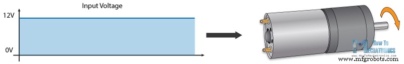
我们可以通过简单地控制电机的输入电压来控制直流电机的速度,最常见的方法是使用 PWM 信号。
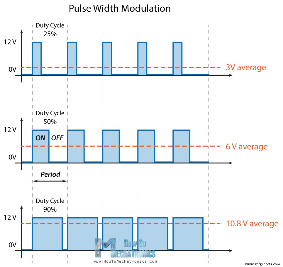
PWM或脉冲宽度调制是一种技术,它允许我们通过快速打开和关闭电源来调整进入电子设备的电压平均值。平均电压取决于占空比,即信号开启的时间量与单个时间段内信号关闭的时间量的关系。
因此,根据电机的大小,我们可以简单地将 Arduino PWM 输出连接到晶体管的基极或 MOSFET 的栅极,并通过控制 PWM 输出来控制电机的速度。低功率 Arduino PWM 信号打开和关闭驱动大功率电机的 MOSFET 的栅极。
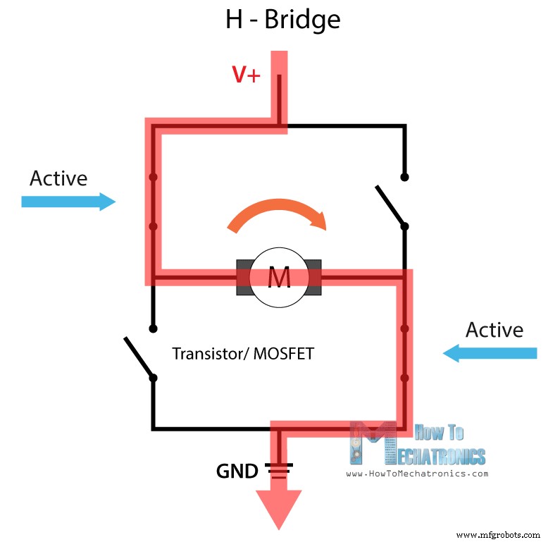
另一方面,为了控制旋转方向,我们只需要反转流过电机的电流方向,最常见的方法是使用 H 桥。 H 桥电路包含四个开关元件、晶体管或 MOSFET,电机位于中心,形成类似 H 的配置。通过同时激活两个特定的开关,我们可以改变电流的方向,从而改变电机的旋转方向。
因此,如果我们结合这两种方法,PWM 和 H 桥,我们可以完全控制直流电机。有许多直流电机驱动器具有这些功能,L298N 就是其中之一。
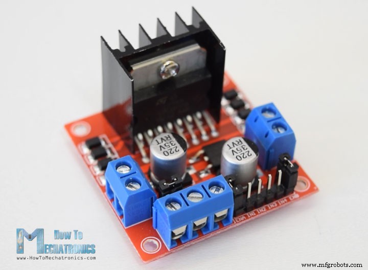
L298N 是一款双 H 桥电机驱动器,可同时控制两个直流电机的速度和方向。该模块可驱动电压在5-35V之间的直流电机,峰值电流可达2A。
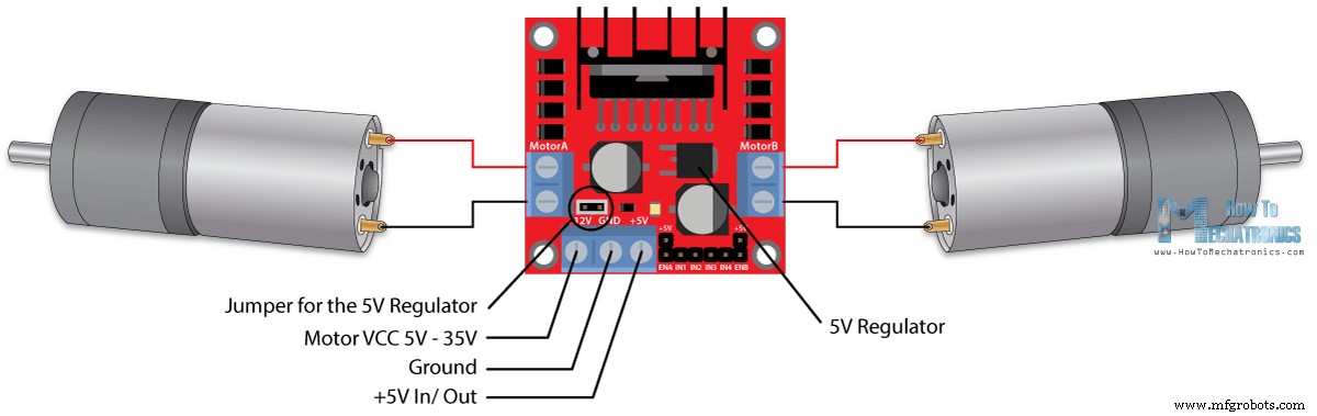
让我们仔细看看 L298N 模块的引脚排列并解释它是如何工作的。该模块有两个用于电机 A 和 B 的螺钉接线端子,另一个用于接地引脚的螺钉接线端子,用于电机的 VCC 和一个可以作为输入或输出的 5V 引脚。
这取决于电机 VCC 上使用的电压。该模块有一个板载 5V 稳压器,可以使用跳线启用或禁用。如果电机电源电压高达 12V,我们可以启用 5V 稳压器,并且 5V 引脚可以用作输出,例如为我们的 Arduino 板供电。但如果电机电压大于 12V,我们必须断开跳线,因为这些电压会损坏板载 5V 稳压器。在这种情况下,5V 引脚将用作输入,因为我们需要将其连接到 5V 电源,以便 IC 正常工作。
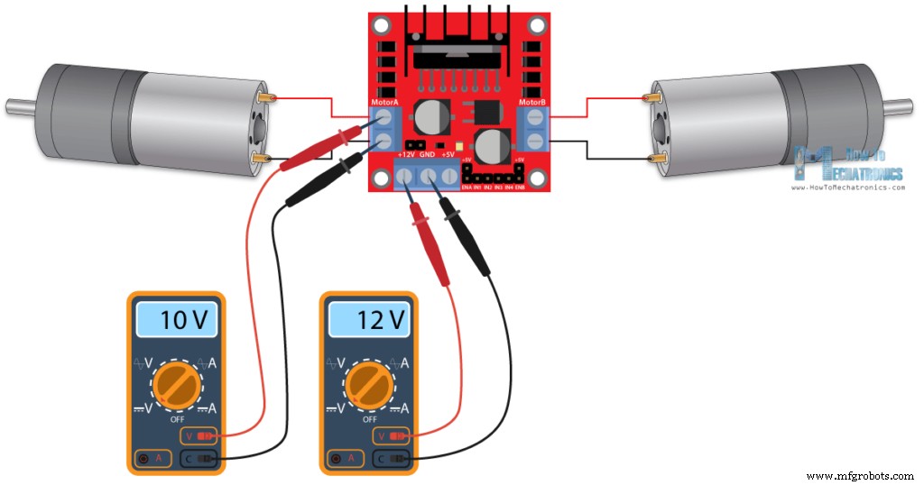
我们可以注意到,这个 IC 产生了大约 2V 的电压降。例如,如果我们使用 12V 电源,电机端子处的电压将约为 10V,这意味着我们将无法从 12V 直流电机中获得最大速度。
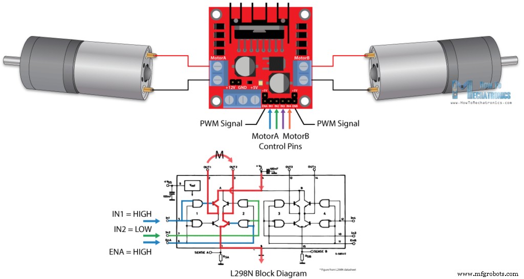
接下来是逻辑控制输入。 Enable A 和 Enable B 引脚用于启用和控制电机的速度。如果此引脚上存在跳线,则电机将启用并以最大速度工作,如果我们移除跳线,我们可以将 PWM 输入连接到此引脚并以这种方式控制电机的速度。如果我们将此引脚连接到地,电机将被禁用。
接下来,输入 1 和输入 2 引脚用于控制电机 A 的旋转方向,输入 3 和 4 用于电机 B。使用这些引脚,我们实际上控制了 L298N IC 内部 H 桥的开关。如果输入 1 为低电平且输入 2 为高电平,则电机将向前移动,反之亦然,如果输入 1 为高电平且输入 2 为低电平,则电机将向后移动。如果两个输入相同,无论是低电平还是高电平,电机都会停止。这同样适用于输入 3 和 4 以及电机 B。
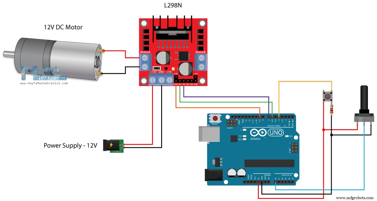
现在让我们做一些实际的应用。在第一个示例中,我们将使用电位计控制电机的速度,并使用按钮更改旋转方向。这是电路原理图。
所以我们需要一个L298N电机驱动器、一个直流电机、一个电位器、一个按钮和一个Arduino板。
您可以从以下链接获取本 Arduino 教程所需的组件:
这是Arduino代码:
说明: 所以首先我们需要定义程序所需的引脚和一些变量。在设置部分,我们需要设置引脚模式和电机的初始旋转方向。在循环部分,我们首先读取电位器值,然后将我们从中获得的值(从 0 到 1023)映射到 0 到 255 的 PWM 信号值,或者是 0 到 100% 的占空比脉宽调制信号。然后使用analogWrite()函数,我们将PWM信号发送到L298N板的Enable引脚,实际驱动电机。
接下来,我们检查我们是否按下了按钮,如果是,我们将通过相反设置输入 1 和输入 2 状态来改变电机的旋转方向。按钮将用作切换按钮,每次按下它都会改变电机的旋转方向。
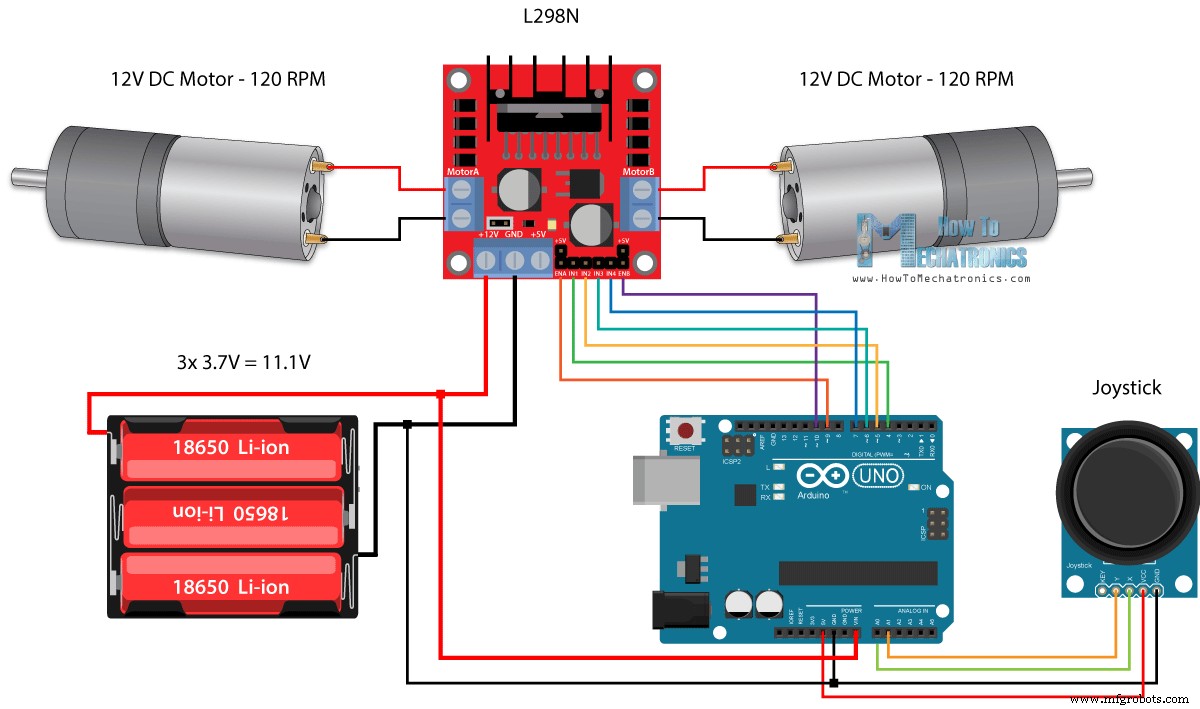
因此,一旦我们了解了这一点,现在我们就可以构建自己的 Arduino 机器人汽车了。电路原理图如下:
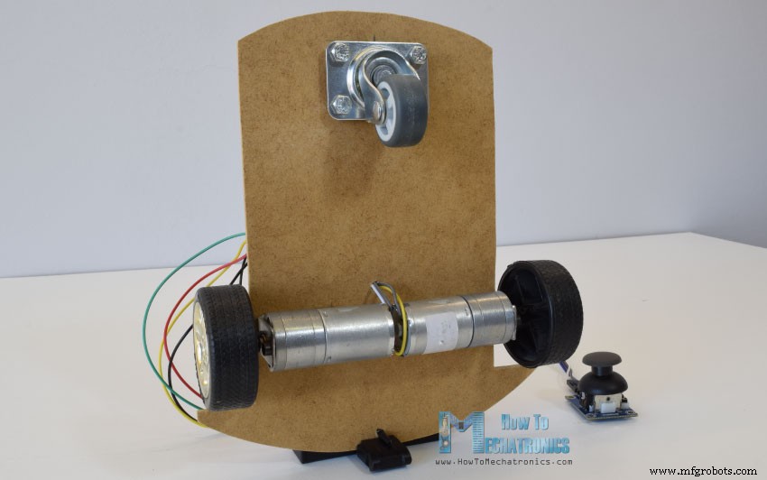
我们只需要 2 个直流电机、L298N 电机驱动器、一个 Arduino 板和一个用于控制的操纵杆。至于电源,我选择了三节3.7V的锂电池,一共提供11V。我用 3 毫米厚的胶合板制作了底盘,用金属支架将电机连接到它上面,将轮子连接到电机上,并在前面连接了一个旋转轮。
现在让我们看一下 Arduino 代码,看看它是如何工作的。 (下面你可以找到完整的代码)
定义引脚后,在循环部分,我们从读取操纵杆 X 和 Y 轴值开始。操纵杆实际上由两个电位器组成,它们连接到 Arduino 的模拟输入,它们的值从 0 到 1023。当操纵杆保持在其中心位置时,两个电位器或轴的值都在 512 左右。
我们将添加一点容差,并以 470 到 550 的值作为中心。因此,如果我们向后移动操纵杆的 Y 轴并且值低于 470,我们将使用四个输入引脚将两个电机的旋转方向设置为向后。然后,我们将从 470 到 0 的递减值转换为从 0 到 255 递增的 PWM 值,这实际上是电机的速度。
类似地,如果我们向前移动操纵杆的 Y 轴并且值超过 550,我们将设置电机向前移动并将读数从 550 到 1023 转换为从 0 到 255 的 PWM 值。如果操纵杆保持在其中心,则电机速度为零。
接下来看看我们如何使用X轴来控制汽车的左右。
同样,首先我们需要将 X 轴读数转换为从 0 到 255 的速度值。为了向左移动,我们使用该值来降低左侧电机速度并增加右侧电机速度。在这里,由于算术函数的原因,我们使用了两个额外的“if”语句来将电机速度的范围限制在 0 到 255 之间。
同样的方法用于将汽车向右移动。
相关:如何使用 555 定时器 IC 制作 PWM 直流电机速度控制器
根据所施加的电压和电机本身,在较低的速度下,电机无法开始移动并产生嗡嗡声。在我的情况下,如果 PWM 信号的值低于 70,则电机无法移动。因此,使用这两个 if 语句,我实际上将速度范围限制在 70 到 255 之间。最后,我们只发送最终的电机速度或PWM信号到L298N驱动器的使能管脚。
下面是Arduino机器人小车示例的完整代码:
以上就是本教程的全部内容了,在我的下一个视频中,我们将通过添加蓝牙和无线电设备来升级这款 Arduino 机器人汽车,以实现智能手机和无线控制。
随时在下面的评论部分提出任何问题,不要忘记查看我收集的 Arduino 项目。
PWM 直流电机控制
H 桥直流电机控制
L298N 驱动程序
Arduino 和 L298N 电机驱动器
Arduino 代码
/*  Arduino DC Motor Control - PWM | H-Bridge | L298N  -  Example 01

    by Dejan Nedelkovski, www.HowToMechatronics.com
*/

#define enA 9
#define in1 6
#define in2 7
#define button 4

int rotDirection = 0;
int pressed = false;

void setup() {
  pinMode(enA, OUTPUT);
  pinMode(in1, OUTPUT);
  pinMode(in2, OUTPUT);
  pinMode(button, INPUT);
  // Set initial rotation direction
  digitalWrite(in1, LOW);
  digitalWrite(in2, HIGH);
}

void loop() {
  int potValue = analogRead(A0); // Read potentiometer value
  int pwmOutput = map(potValue, 0, 1023, 0 , 255); // Map the potentiometer value from 0 to 255
  analogWrite(enA, pwmOutput); // Send PWM signal to L298N Enable pin

  // Read button - Debounce
  if (digitalRead(button) == true) {
    pressed = !pressed;
  }
  while (digitalRead(button) == true);
  delay(20);

  // If button is pressed - change rotation direction
  if (pressed == true  & rotDirection == 0) {
    digitalWrite(in1, HIGH);
    digitalWrite(in2, LOW);
    rotDirection = 1;
    delay(20);
  }
  // If button is pressed - change rotation direction
  if (pressed == false & rotDirection == 1) {
    digitalWrite(in1, LOW);
    digitalWrite(in2, HIGH);
    rotDirection = 0;
    delay(20);
  }
}
Code language: Arduino (arduino)使用 L298N 电机驱动器的 Arduino 机器人汽车控制
int xAxis = analogRead(A0); // Read Joysticks X-axis
int yAxis = analogRead(A1); // Read Joysticks Y-axisCode language: Arduino (arduino)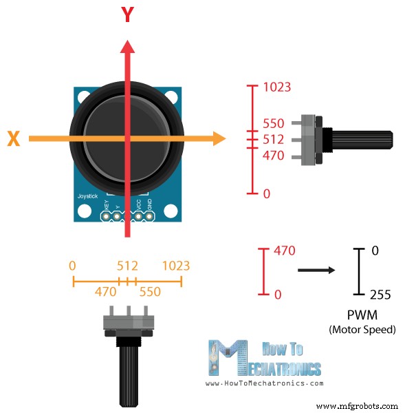
// Y-axis used for forward and backward control
  if (yAxis < 470) {
    // Set Motor A backward
    digitalWrite(in1, HIGH);
    digitalWrite(in2, LOW);
    // Set Motor B backward
    digitalWrite(in3, HIGH);
    digitalWrite(in4, LOW);
    // Convert the declining Y-axis readings for going backward from 470 to 0 into 0 to 255 value for the PWM signal for increasing the motor speed
    motorSpeedA = map(yAxis, 470, 0, 0, 255);
    motorSpeedB = map(yAxis, 470, 0, 0, 255);
}Code language: Arduino (arduino)// X-axis used for left and right control
if (xAxis < 470) {
// Convert the declining X-axis readings from 470 to 0 into increasing 0 to 255 value
int xMapped = map(xAxis, 470, 0, 0, 255);
// Move to left - decrease left motor speed, increase right motor speed
motorSpeedA = motorSpeedA - xMapped;
motorSpeedB = motorSpeedB + xMapped;
// Confine the range from 0 to 255
if (motorSpeedA < 0) {
motorSpeedA = 0;
}
if (motorSpeedB > 255) {
motorSpeedB = 255;
}
}Code language: Arduino (arduino)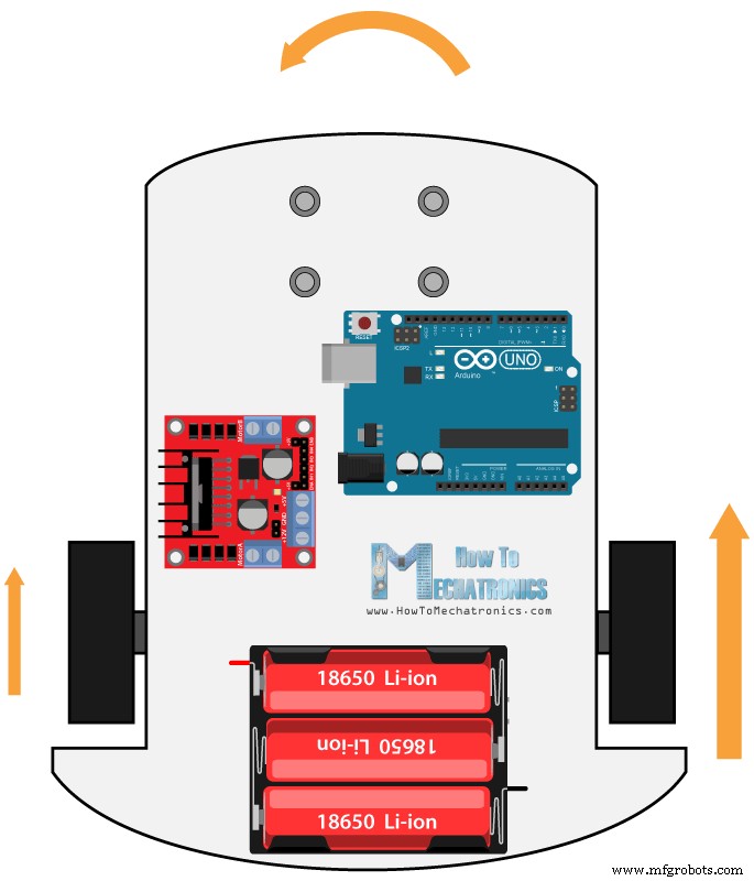
// Prevent buzzing at low speeds (Adjust according to your motors. My motors couldn't start moving if PWM value was below value of 70)
  if (motorSpeedA < 70) {
    motorSpeedA = 0;
  }
  if (motorSpeedB < 70) {
    motorSpeedB = 0;
  }
  analogWrite(enA, motorSpeedA); // Send PWM signal to motor A
analogWrite(enB, motorSpeedB); // Send PWM signal to motor BCode language: Arduino (arduino)/* Arduino DC Motor Control - PWM | H-Bridge | L298N
Example 02 - Arduino Robot Car Control
by Dejan Nedelkovski, www.HowToMechatronics.com
*/
#define enA 9
#define in1 4
#define in2 5
#define enB 10
#define in3 6
#define in4 7
int motorSpeedA = 0;
int motorSpeedB = 0;
void setup() {
pinMode(enA, OUTPUT);
pinMode(enB, OUTPUT);
pinMode(in1, OUTPUT);
pinMode(in2, OUTPUT);
pinMode(in3, OUTPUT);
pinMode(in4, OUTPUT);
}
void loop() {
int xAxis = analogRead(A0); // Read Joysticks X-axis
int yAxis = analogRead(A1); // Read Joysticks Y-axis
// Y-axis used for forward and backward control
if (yAxis < 470) {
// Set Motor A backward
digitalWrite(in1, HIGH);
digitalWrite(in2, LOW);
// Set Motor B backward
digitalWrite(in3, HIGH);
digitalWrite(in4, LOW);
// Convert the declining Y-axis readings for going backward from 470 to 0 into 0 to 255 value for the PWM signal for increasing the motor speed
motorSpeedA = map(yAxis, 470, 0, 0, 255);
motorSpeedB = map(yAxis, 470, 0, 0, 255);
}
else if (yAxis > 550) {
// Set Motor A forward
digitalWrite(in1, LOW);
digitalWrite(in2, HIGH);
// Set Motor B forward
digitalWrite(in3, LOW);
digitalWrite(in4, HIGH);
// Convert the increasing Y-axis readings for going forward from 550 to 1023 into 0 to 255 value for the PWM signal for increasing the motor speed
motorSpeedA = map(yAxis, 550, 1023, 0, 255);
motorSpeedB = map(yAxis, 550, 1023, 0, 255);
}
// If joystick stays in middle the motors are not moving
else {
motorSpeedA = 0;
motorSpeedB = 0;
}
// X-axis used for left and right control
if (xAxis < 470) {
// Convert the declining X-axis readings from 470 to 0 into increasing 0 to 255 value
int xMapped = map(xAxis, 470, 0, 0, 255);
// Move to left - decrease left motor speed, increase right motor speed
motorSpeedA = motorSpeedA - xMapped;
motorSpeedB = motorSpeedB + xMapped;
// Confine the range from 0 to 255
if (motorSpeedA < 0) {
motorSpeedA = 0;
}
if (motorSpeedB > 255) {
motorSpeedB = 255;
}
}
if (xAxis > 550) {
// Convert the increasing X-axis readings from 550 to 1023 into 0 to 255 value
int xMapped = map(xAxis, 550, 1023, 0, 255);
// Move right - decrease right motor speed, increase left motor speed
motorSpeedA = motorSpeedA + xMapped;
motorSpeedB = motorSpeedB - xMapped;
// Confine the range from 0 to 255
if (motorSpeedA > 255) {
motorSpeedA = 255;
}
if (motorSpeedB < 0) {
motorSpeedB = 0;
}
}
// Prevent buzzing at low speeds (Adjust according to your motors. My motors couldn't start moving if PWM value was below value of 70)
if (motorSpeedA < 70) {
motorSpeedA = 0;
}
if (motorSpeedB < 70) {
motorSpeedB = 0;
}
analogWrite(enA, motorSpeedA); // Send PWM signal to motor A
analogWrite(enB, motorSpeedB); // Send PWM signal to motor B
}Code language: Arduino (arduino)
制造工艺