

使用 HC-05 蓝牙、NRF24L01 和 HC-12 收发器模块的 Arduino 机器人汽车无线控制
在本教程中,我们将学习如何无线控制我们在上一个视频中制作的 Arduino 机器人汽车。我将向您展示三种不同的无线控制方法,分别使用 HC-05 蓝牙模块、NRF24L01 收发器模块和 HC-12 远程无线模块,以及使用智能手机和定制的 Android 应用程序。您可以观看以下视频或阅读下面的书面教程了解更多详情。
我已经有关于如何将这些模块与 Arduino 板连接和使用的教程,所以如果您需要更多详细信息,您可以随时查看它们。可以在下面的文章中找到它们的链接。
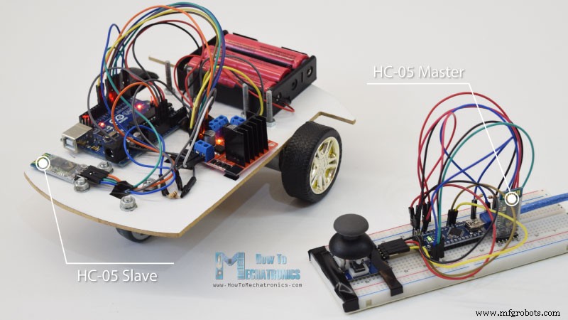
我们将从蓝牙通信开始,为此我们需要两个 HC-05 蓝牙模块,需要配置为主设备和从设备。
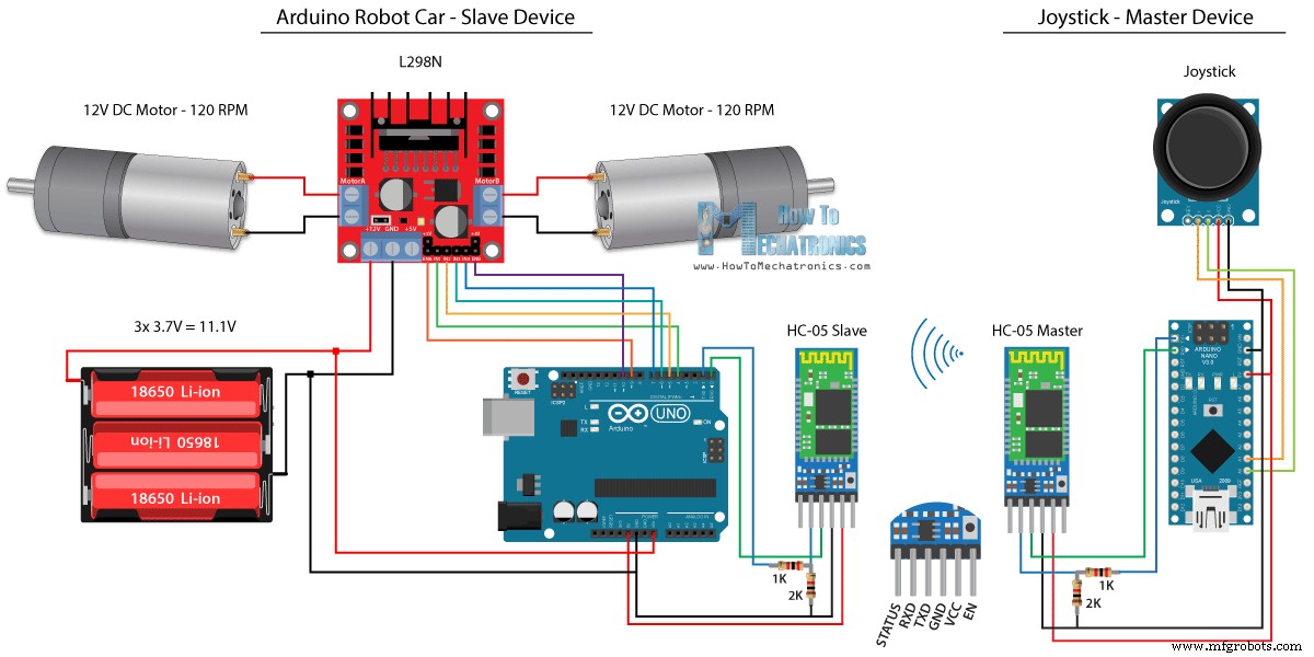
我们可以通过使用 AT 命令轻松做到这一点,我将操纵杆设置为主机,将 Arduino 机器人汽车设置为从机。下面是这个例子的完整电路原理图:
您可以从以下链接获取此示例所需的组件:
我们将使用上一个教程中相同的代码,其中我们直接使用操纵杆控制 Arduino 机器人小车,我们将对其进行一些修改。
HC-05 主码:
主设备或操纵杆上的代码非常简单。我们只需要读取操纵杆的 X 和 Y 值,这实际上是在调节电机的速度,并通过串口发送到从机 HC-05 蓝牙设备。这里我们可以注意到,摇杆的模拟值从 0 到 1023 被转换为从 0 到 255 的值,通过将它们除以 4。
我们这样做是因为可以通过蓝牙设备以 1 字节的形式发送从 0 到 255 的范围,这在另一端或 Arduino 机器人车上更容易接受。
所以在这里,如果串口收到了 2 个字节,即 X 和 Y 值,使用 Serial.read() 函数我们将读取它们。
现在我们只需要将值转换回 0 到 1023 的范围,适合下面的电机控制代码,我们已经在上一个视频中解释了它是如何工作的。
请注意,在上传代码时,我们需要断开 Arduino 板的 RX 和 TX 引脚。
完整的 HC-05 从属代码:
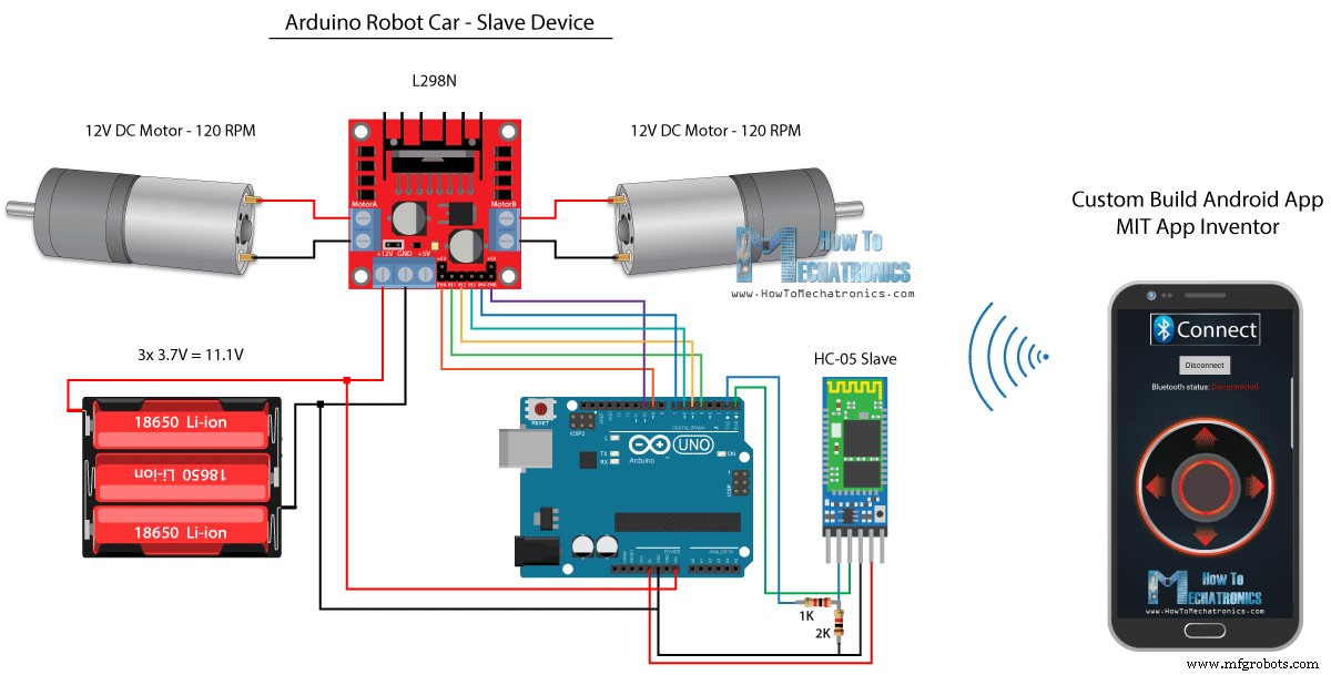
接下来,让我们看看我们如何使用定制的 Android 应用程序来控制我们的 Arduino 机器人汽车。机器人小车的电路原理图与上例一模一样,设置为HC-05蓝牙模式为从设备。
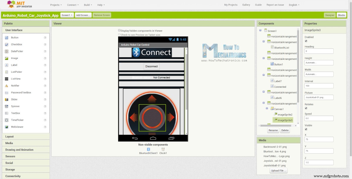
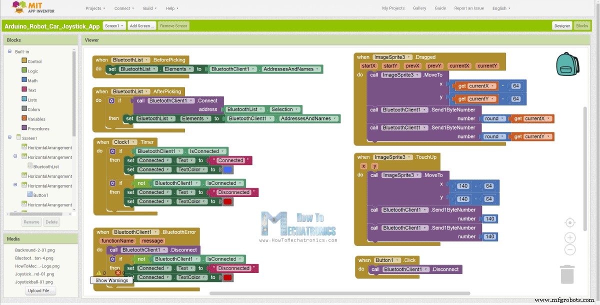
另一方面,使用 MIT App Inventor 在线应用程序,我们将构建自己的 Android 应用程序,如下所示。
因此,该应用程序基本上模拟了一个操纵杆,其外观由两个图像或图像精灵组成。
如果我们看一下这个应用程序的块,我们可以看到当操纵杆精灵被拖动时,操纵杆球的图像移动到我们手指的当前位置,同时我们发送 X 和 Y通过蓝牙将值传递给 Arduino 汽车。
Arduino 使用 Serial.read 函数以与上一个示例相同的方式接受这些值。
这里我们需要额外做的是将智能手机接收到的 X 和 Y 值转换为 0 到 1023 的范围,适用于下面的电机控制代码。这些值取决于画布大小,我从我的应用程序中获得的 X 和 Y 值是从 60 到 220,使用 map() 函数我很容易转换它们。
在应用程序块中,我们还可以看到,当图像精灵被触摸时,操纵杆球移回画布中心,并向汽车发送适当的值以停止移动。您可以在网站文章中找到并下载此应用程序以及操纵杆的两个图像,以便您构建自己的应用程序或修改此应用程序。
您可以下载下面的Android App,以及摇杆的两张图片:
完整的 Arduino 代码:
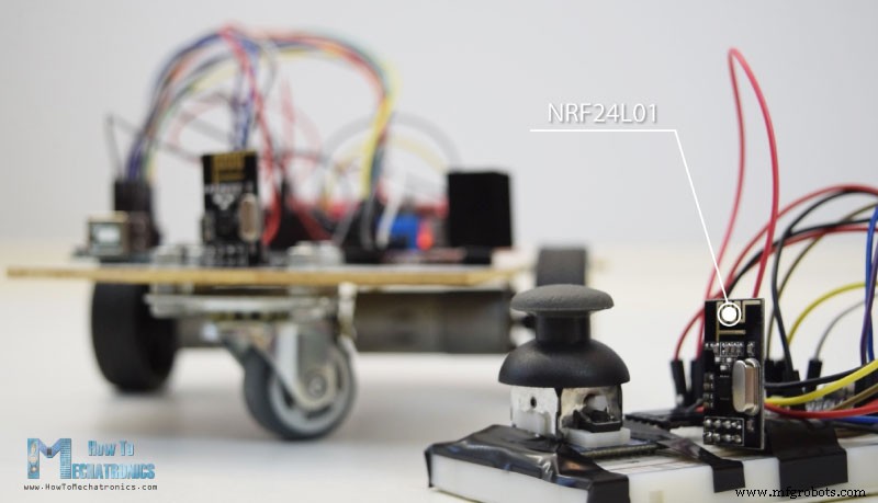
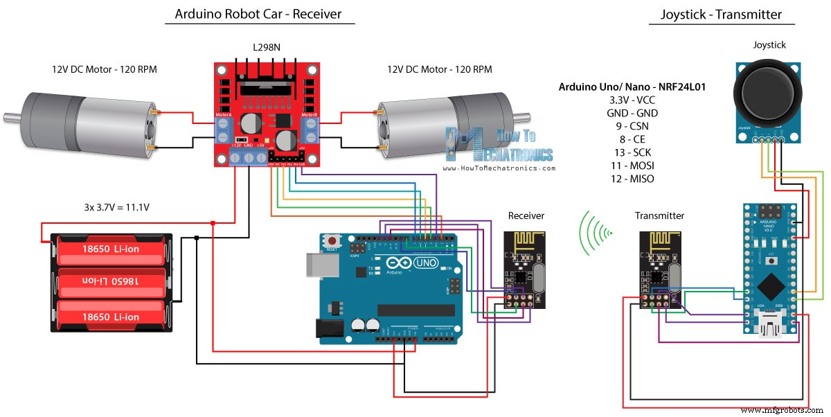
现在我们可以继续下一个方法,使用 NRF24L01 收发器模块对 Arduino 机器人小车进行无线控制。
这是电路原理图。我们可以注意到这些模块使用 SPI 通信,因此与前面的示例相比,我将 L298N 驱动程序的 Enable A 和 Enable B 引脚移动到 Arduino 板的 2 号和 3 号引脚。你可以得到 NRF24L01以下亚马逊链接上的模块.
对于此示例,我们需要安装 RF24 库。与上例类似,在定义一些引脚并将模块设置为发射器后,我们读取操纵杆的 X 和 Y 值并将它们发送到 Arduino 机器人车上的另一个 NRF24L01 模块。
首先我们可以注意到模拟读数是字符串,使用 string.toCharArray() 函数将其放入字符数组中。然后使用 radio.write() 函数将字符数组数据发送到另一个模块。
发射机代码:
另一方面。在 Arduino 机器人车上,将模块定义为接收器后,我们使用 radio.read() 函数接收数据。然后使用 atoi() 函数我们将接收到的数据,或者操纵杆的 X 和 Y 值转换为整数值,适合下面的电机控制代码。
就这么简单,当然正如我已经说过的,如果您需要更多关于如何连接和设置模块的详细信息,您可以随时查看我的特定教程。
接收方代码:
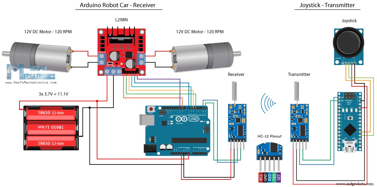
对于Arduino机器人汽车的最后一种无线控制方法,我们将使用HC-12远程收发模块。这些模块之间的通信距离可达 1.8 公里。
本例的电路原理图与 HC-05 蓝牙模块的电路原理图几乎相同,因为它们使用相同的方法通过串口与 Arduino 通信。
您可以通过以下亚马逊链接获取 HC-12 收发器模块。
操纵杆代码与蓝牙通信的代码完全相同。我们只是读取操纵杆的模拟值,然后使用 Serial.write() 函数将它们发送到另一个模块。
发射机代码:
另一方面,通过 while() 循环,我们等待数据到达,然后使用 Serial.read() 函数读取数据并将其转换回 0 到 1023 范围,适用于下面的电机控制代码。
收货人代码:
这就是本教程的几乎所有内容。欢迎在下方评论区提出任何问题。使用 HC-05 蓝牙模块的 Arduino 机器人汽车控制
源代码
/*
   Arduino Robot Car Wireless Control using the HC-05 Bluetooth

                == MASTER DEVICE - Joystick ==

   by Dejan Nedelkovski, www.HowToMechatronics.com
*/

int xAxis, yAxis;

void setup() {
  Serial.begin(38400); // Default communication rate of the Bluetooth module
}

void loop() {
  xAxis = analogRead(A0); // Read Joysticks X-axis
  yAxis = analogRead(A1); // Read Joysticks Y-axis

  // Send the values via the serial port to the slave HC-05 Bluetooth device
  Serial.write(xAxis/4); // Dividing by 4 for converting from 0 - 1023 to 0 - 256, (1 byte) range
  Serial.write(yAxis/4);
  delay(20);
}Code language: Arduino (arduino)// Code from the Arduino Robot Car
// Read the incoming data from the Joystick, or the master Bluetooth device
while (Serial.available() >= 2) {
x = Serial.read();
delay(10);
y = Serial.read();
}Code language: Arduino (arduino)// Code from the Arduino Robot Car
// Convert back the 0 - 255 range to 0 - 1023, suitable for motor control code below
xAxis = x*4;
yAxis = y*4;Code language: Arduino (arduino)/*
Arduino Robot Car Wireless Control using the HC-05 Bluetooth
== SLAVE DEVICE - Arduino robot car ==
by Dejan Nedelkovski, www.HowToMechatronics.com
*/
#define enA 9
#define in1 4
#define in2 5
#define enB 10
#define in3 6
#define in4 7
int xAxis, yAxis;
unsigned int x = 0;
unsigned int y = 0;
int motorSpeedA = 0;
int motorSpeedB = 0;
void setup() {
pinMode(enA, OUTPUT);
pinMode(enB, OUTPUT);
pinMode(in1, OUTPUT);
pinMode(in2, OUTPUT);
pinMode(in3, OUTPUT);
pinMode(in4, OUTPUT);
Serial.begin(38400); // Default communication rate of the Bluetooth module
}
void loop() {
// Default value - no movement when the Joystick stays in the center
x = 510 / 4;
y = 510 / 4;
// Read the incoming data from the Joystick, or the master Bluetooth device
while (Serial.available() >= 2) {
x = Serial.read();
delay(10);
y = Serial.read();
}
delay(10);
// Convert back the 0 - 255 range to 0 - 1023, suitable for motor control code below
xAxis = x*4;
yAxis = y*4;
// Y-axis used for forward and backward control
if (yAxis < 470) {
// Set Motor A backward
digitalWrite(in1, HIGH);
digitalWrite(in2, LOW);
// Set Motor B backward
digitalWrite(in3, HIGH);
digitalWrite(in4, LOW);
// Convert the declining Y-axis readings for going backward from 470 to 0 into 0 to 255 value for the PWM signal for increasing the motor speed
motorSpeedA = map(yAxis, 470, 0, 0, 255);
motorSpeedB = map(yAxis, 470, 0, 0, 255);
}
else if (yAxis > 550) {
// Set Motor A forward
digitalWrite(in1, LOW);
digitalWrite(in2, HIGH);
// Set Motor B forward
digitalWrite(in3, LOW);
digitalWrite(in4, HIGH);
// Convert the increasing Y-axis readings for going forward from 550 to 1023 into 0 to 255 value for the PWM signal for increasing the motor speed
motorSpeedA = map(yAxis, 550, 1023, 0, 255);
motorSpeedB = map(yAxis, 550, 1023, 0, 255);
}
// If joystick stays in middle the motors are not moving
else {
motorSpeedA = 0;
motorSpeedB = 0;
}
// X-axis used for left and right control
if (xAxis < 470) {
// Convert the declining X-axis readings from 470 to 0 into increasing 0 to 255 value
int xMapped = map(xAxis, 470, 0, 0, 255);
// Move to left - decrease left motor speed, increase right motor speed
motorSpeedA = motorSpeedA - xMapped;
motorSpeedB = motorSpeedB + xMapped;
// Confine the range from 0 to 255
if (motorSpeedA < 0) {
motorSpeedA = 0;
}
if (motorSpeedB > 255) {
motorSpeedB = 255;
}
}
if (xAxis > 550) {
// Convert the increasing X-axis readings from 550 to 1023 into 0 to 255 value
int xMapped = map(xAxis, 550, 1023, 0, 255);
// Move right - decrease right motor speed, increase left motor speed
motorSpeedA = motorSpeedA + xMapped;
motorSpeedB = motorSpeedB - xMapped;
// Confine the range from 0 to 255
if (motorSpeedA > 255) {
motorSpeedA = 255;
}
if (motorSpeedB < 0) {
motorSpeedB = 0;
}
}
// Prevent buzzing at low speeds (Adjust according to your motors. My motors couldn't start moving if PWM value was below value of 70)
if (motorSpeedA < 70) {
motorSpeedA = 0;
}
if (motorSpeedB < 70) {
motorSpeedB = 0;
}
analogWrite(enA, motorSpeedA); // Send PWM signal to motor A
analogWrite(enB, motorSpeedB); // Send PWM signal to motor B
}Code language: Arduino (arduino)Arduino 机器人汽车控制使用智能手机和自定义构建的 Android 应用程序
// Read the incoming data from the Smartphone Android App
  while (Serial.available() >= 2) {
    x = Serial.read();
    delay(10);
    y = Serial.read();
}Code language: Arduino (arduino)// Makes sure we receive corrent values
if (x > 60 & x < 220) {
xAxis = map(x, 220, 60, 1023, 0); // Convert the smartphone X and Y values to 0 - 1023 range, suitable motor for the motor control code below
}
if (y > 60 & y < 220) {
yAxis = map(y, 220, 60, 0, 1023);
}Code language: Arduino (arduino)
Arduino_Robot_Car_Joystick_App.apk
1 个文件 1.62 MB 下载 Arduino_Robot_Car_Joystick_App_aia_file
1 个文件 171.20 KB 下载 操纵杆应用图片
1 个文件 44.36 KB 下载 /*
Arduino Robot Car Wireless Control using the HC-05 Bluetooth and custom-build Android app
== SLAVE DEVICE - Arduino robot car ==
by Dejan Nedelkovski, www.HowToMechatronics.com
*/
#define enA 9
#define in1 4
#define in2 5
#define enB 10
#define in3 6
#define in4 7
int xAxis, yAxis;
int x = 0;
int y = 0;
int motorSpeedA = 0;
int motorSpeedB = 0;
void setup() {
pinMode(enA, OUTPUT);
pinMode(enB, OUTPUT);
pinMode(in1, OUTPUT);
pinMode(in2, OUTPUT);
pinMode(in3, OUTPUT);
pinMode(in4, OUTPUT);
Serial.begin(38400); // Default communication rate of the Bluetooth module
}
void loop() {
// Default value - no movement when the Joystick stays in the center
xAxis = 510;
yAxis = 510;
// Read the incoming data from the Smartphone Android App
while (Serial.available() >= 2) {
x = Serial.read();
delay(10);
y = Serial.read();
}
delay(10);
// Makes sure we receive corrent values
if (x > 60 & x < 220) {
xAxis = map(x, 220, 60, 1023, 0); // Convert the smartphone X and Y values to 0 - 1023 range, suitable motor for the motor control code below
}
if (y > 60 & y < 220) {
yAxis = map(y, 220, 60, 0, 1023);
}
// Y-axis used for forward and backward control
if (yAxis < 470) {
// Set Motor A backward
digitalWrite(in1, HIGH);
digitalWrite(in2, LOW);
// Set Motor B backward
digitalWrite(in3, HIGH);
digitalWrite(in4, LOW);
// Convert the declining Y-axis readings for going backward from 470 to 0 into 0 to 255 value for the PWM signal for increasing the motor speed
motorSpeedA = map(yAxis, 470, 0, 0, 255);
motorSpeedB = map(yAxis, 470, 0, 0, 255);
}
else if (yAxis > 550) {
// Set Motor A forward
digitalWrite(in1, LOW);
digitalWrite(in2, HIGH);
// Set Motor B forward
digitalWrite(in3, LOW);
digitalWrite(in4, HIGH);
// Convert the increasing Y-axis readings for going forward from 550 to 1023 into 0 to 255 value for the PWM signal for increasing the motor speed
motorSpeedA = map(yAxis, 550, 1023, 0, 255);
motorSpeedB = map(yAxis, 550, 1023, 0, 255);
}
// If joystick stays in middle the motors are not moving
else {
motorSpeedA = 0;
motorSpeedB = 0;
}
// X-axis used for left and right control
if (xAxis < 470) {
// Convert the declining X-axis readings from 470 to 0 into increasing 0 to 255 value
int xMapped = map(xAxis, 470, 0, 0, 255);
// Move to left - decrease left motor speed, increase right motor speed
motorSpeedA = motorSpeedA - xMapped;
motorSpeedB = motorSpeedB + xMapped;
// Confine the range from 0 to 255
if (motorSpeedA < 0) {
motorSpeedA = 0;
}
if (motorSpeedB > 255) {
motorSpeedB = 255;
}
}
if (xAxis > 550) {
// Convert the increasing X-axis readings from 550 to 1023 into 0 to 255 value
int xMapped = map(xAxis, 550, 1023, 0, 255);
// Move right - decrease right motor speed, increase left motor speed
motorSpeedA = motorSpeedA + xMapped;
motorSpeedB = motorSpeedB - xMapped;
// Confine the range from 0 to 255
if (motorSpeedA > 255) {
motorSpeedA = 255;
}
if (motorSpeedB < 0) {
motorSpeedB = 0;
}
}
// Prevent buzzing at low speeds (Adjust according to your motors. My motors couldn't start moving if PWM value was below value of 70)
if (motorSpeedA < 70) {
motorSpeedA = 0;
}
if (motorSpeedB < 70) {
motorSpeedB = 0;
}
analogWrite(enA, motorSpeedA); // Send PWM signal to motor A
analogWrite(enB, motorSpeedB); // Send PWM signal to motor B
}Code language: Arduino (arduino)使用NRF24L01收发模块的Arduino机器人汽车无线控制
源代码
/*
   Arduino Robot Car Wireless Control using the NRF24L01 Transceiver module

             == Transmitter - Joystick ==

   by Dejan Nedelkovski, www.HowToMechatronics.com

   Library: TMRh20/RF24, https://github.com/tmrh20/RF24/
*/

#include <SPI.h>
#include <nRF24L01.h>
#include <RF24.h>

RF24 radio(8, 9); // CE, CSN
const byte address[6] = "00001";

char xyData[32] = "";
String xAxis, yAxis;

void setup() {
  Serial.begin(9600);
  radio.begin();
  radio.openWritingPipe(address);
  radio.setPALevel(RF24_PA_MIN);
  radio.stopListening();
}

void loop() {

  xAxis = analogRead(A0); // Read Joysticks X-axis
  yAxis = analogRead(A1); // Read Joysticks Y-axis
  // X value
  xAxis.toCharArray(xyData, 5); // Put the String (X Value) into a character array
  radio.write(&xyData, sizeof(xyData)); // Send the array data (X value) to the other NRF24L01 modile
  // Y value
  yAxis.toCharArray(xyData, 5);
  radio.write(&xyData, sizeof(xyData));
  delay(20);
}Code language: Arduino (arduino)// Code from the Arduino Robot Car - NRF24L01 example
if (radio.available()) { // If the NRF240L01 module received data
radio.read(&receivedData, sizeof(receivedData)); // Read the data and put it into character array
xAxis = atoi(&receivedData[0]); // Convert the data from the character array (received X value) into integer
delay(10);
radio.read(&receivedData, sizeof(receivedData));
yAxis = atoi(&receivedData[0]);
delay(10);
}Code language: Arduino (arduino)/*
Arduino Robot Car Wireless Control using the NRF24L01 Transceiver module
== Receiver - Arduino robot car ==
by Dejan Nedelkovski, www.HowToMechatronics.com
Library: TMRh20/RF24, https://github.com/tmrh20/RF24/
*/
#include <SPI.h>
#include <nRF24L01.h>
#include <RF24.h>
#define enA 2 // Note: Pin 9 in previous video ( pin 10 is used for the SPI communication of the NRF24L01)
#define in1 4
#define in2 5
#define enB 3 // Note: Pin 10 in previous video
#define in3 6
#define in4 7
RF24 radio(8, 9); // CE, CSN
const byte address[6] = "00001";
char receivedData[32] = "";
int xAxis, yAxis;
int motorSpeedA = 0;
int motorSpeedB = 0;
void setup() {
pinMode(enA, OUTPUT);
pinMode(enB, OUTPUT);
pinMode(in1, OUTPUT);
pinMode(in2, OUTPUT);
pinMode(in3, OUTPUT);
pinMode(in4, OUTPUT);
Serial.begin(9600);
radio.begin();
radio.openReadingPipe(0, address);
radio.setPALevel(RF24_PA_MIN);
radio.startListening();
}
void loop() {
if (radio.available()) { // If the NRF240L01 module received data
radio.read(&receivedData, sizeof(receivedData)); // Read the data and put it into character array
xAxis = atoi(&receivedData[0]); // Convert the data from the character array (received X value) into integer
delay(10);
radio.read(&receivedData, sizeof(receivedData));
yAxis = atoi(&receivedData[0]);
delay(10);
}
// Y-axis used for forward and backward control
if (yAxis < 470) {
// Set Motor A backward
digitalWrite(in1, HIGH);
digitalWrite(in2, LOW);
// Set Motor B backward
digitalWrite(in3, HIGH);
digitalWrite(in4, LOW);
// Convert the declining Y-axis readings for going backward from 470 to 0 into 0 to 255 value for the PWM signal for increasing the motor speed
motorSpeedA = map(yAxis, 470, 0, 0, 255);
motorSpeedB = map(yAxis, 470, 0, 0, 255);
}
else if (yAxis > 550) {
// Set Motor A forward
digitalWrite(in1, LOW);
digitalWrite(in2, HIGH);
// Set Motor B forward
digitalWrite(in3, LOW);
digitalWrite(in4, HIGH);
// Convert the increasing Y-axis readings for going forward from 550 to 1023 into 0 to 255 value for the PWM signal for increasing the motor speed
motorSpeedA = map(yAxis, 550, 1023, 0, 255);
motorSpeedB = map(yAxis, 550, 1023, 0, 255);
}
// If joystick stays in middle the motors are not moving
else {
motorSpeedA = 0;
motorSpeedB = 0;
}
// X-axis used for left and right control
if (xAxis < 470) {
// Convert the declining X-axis readings from 470 to 0 into increasing 0 to 255 value
int xMapped = map(xAxis, 470, 0, 0, 255);
// Move to left - decrease left motor speed, increase right motor speed
motorSpeedA = motorSpeedA - xMapped;
motorSpeedB = motorSpeedB + xMapped;
// Confine the range from 0 to 255
if (motorSpeedA < 0) {
motorSpeedA = 0;
}
if (motorSpeedB > 255) {
motorSpeedB = 255;
}
}
if (xAxis > 550) {
// Convert the increasing X-axis readings from 550 to 1023 into 0 to 255 value
int xMapped = map(xAxis, 550, 1023, 0, 255);
// Move right - decrease right motor speed, increase left motor speed
motorSpeedA = motorSpeedA + xMapped;
motorSpeedB = motorSpeedB - xMapped;
// Confine the range from 0 to 255
if (motorSpeedA > 255) {
motorSpeedA = 255;
}
if (motorSpeedB < 0) {
motorSpeedB = 0;
}
}
// Prevent buzzing at low speeds (Adjust according to your motors. My motors couldn't start moving if PWM value was below value of 70)
if (motorSpeedA < 70) {
motorSpeedA = 0;
}
if (motorSpeedB < 70) {
motorSpeedB = 0;
}
analogWrite(enA, motorSpeedA); // Send PWM signal to motor A
analogWrite(enB, motorSpeedB); // Send PWM signal to motor B
}Code language: Arduino (arduino)使用 HC-12 远程收发器的 Arduino 机器人汽车无线控制
源代码
/*
   Arduino Robot Car Wireless Control using the HC-12 long range wireless module

                == Transmitter - Joystick ==

   by Dejan Nedelkovski, www.HowToMechatronics.com
*/

int xAxis, yAxis;

void setup() {
  Serial.begin(9600); // Default communication rate of the Bluetooth module
}

void loop() {
  xAxis = analogRead(A0); // Read Joysticks X-axis
  yAxis = analogRead(A1); // Read Joysticks Y-axis

  // Send the values via the serial port to the slave HC-05 Bluetooth device
  Serial.write(xAxis/4); // Dividing by 4 for converting from 0 - 1023 to 0 - 256, (1 byte) range
  Serial.write(yAxis/4);
  delay(20);
}Code language: Arduino (arduino)/*
Arduino Robot Car Wireless Control using the HC-12 long range wireless module
== Receiver - Arduino robot car ==
by Dejan Nedelkovski, www.HowToMechatronics.com
*/
#define enA 9
#define in1 4
#define in2 5
#define enB 10
#define in3 6
#define in4 7
int xAxis, yAxis;
int x = 0;
int y = 0;
int motorSpeedA = 0;
int motorSpeedB = 0;
void setup() {
pinMode(enA, OUTPUT);
pinMode(enB, OUTPUT);
pinMode(in1, OUTPUT);
pinMode(in2, OUTPUT);
pinMode(in3, OUTPUT);
pinMode(in4, OUTPUT);
Serial.begin(9600); // Default communication rate of the Bluetooth module
}
void loop() {
// Default value - no movement when the Joystick stays in the center
xAxis = 510;
yAxis = 510;
// Read the incoming data from the
while (Serial.available() == 0) {}
x = Serial.read();
delay(10);
y = Serial.read();
delay(10);
// Convert back the 0 - 255 range to 0 - 1023, suitable for motor control code below
xAxis = x * 4;
yAxis = y * 4;
// Y-axis used for forward and backward control
if (yAxis < 470) {
// Set Motor A backward
digitalWrite(in1, HIGH);
digitalWrite(in2, LOW);
// Set Motor B backward
digitalWrite(in3, HIGH);
digitalWrite(in4, LOW);
// Convert the declining Y-axis readings for going backward from 470 to 0 into 0 to 255 value for the PWM signal for increasing the motor speed
motorSpeedA = map(yAxis, 470, 0, 0, 255);
motorSpeedB = map(yAxis, 470, 0, 0, 255);
}
else if (yAxis > 550) {
// Set Motor A forward
digitalWrite(in1, LOW);
digitalWrite(in2, HIGH);
// Set Motor B forward
digitalWrite(in3, LOW);
digitalWrite(in4, HIGH);
// Convert the increasing Y-axis readings for going forward from 550 to 1023 into 0 to 255 value for the PWM signal for increasing the motor speed
motorSpeedA = map(yAxis, 550, 1023, 0, 255);
motorSpeedB = map(yAxis, 550, 1023, 0, 255);
}
// If joystick stays in middle the motors are not moving
else {
motorSpeedA = 0;
motorSpeedB = 0;
}
// X-axis used for left and right control
if (xAxis < 470) {
// Convert the declining X-axis readings from 470 to 0 into increasing 0 to 255 value
int xMapped = map(xAxis, 470, 0, 0, 255);
// Move to left - decrease left motor speed, increase right motor speed
motorSpeedA = motorSpeedA - xMapped;
motorSpeedB = motorSpeedB + xMapped;
// Confine the range from 0 to 255
if (motorSpeedA < 0) {
motorSpeedA = 0;
}
if (motorSpeedB > 255) {
motorSpeedB = 255;
}
}
if (xAxis > 550) {
// Convert the increasing X-axis readings from 550 to 1023 into 0 to 255 value
int xMapped = map(xAxis, 550, 1023, 0, 255);
// Move right - decrease right motor speed, increase left motor speed
motorSpeedA = motorSpeedA + xMapped;
motorSpeedB = motorSpeedB - xMapped;
// Confine the range from 0 to 255
if (motorSpeedA > 255) {
motorSpeedA = 255;
}
if (motorSpeedB < 0) {
motorSpeedB = 0;
}
}
// Prevent buzzing at low speeds (Adjust according to your motors. My motors couldn't start moving if PWM value was below value of 70)
if (motorSpeedA < 70) {
motorSpeedA = 0;
}
if (motorSpeedB < 70) {
motorSpeedB = 0;
}
analogWrite(enA, motorSpeedA); // Send PWM signal to motor A
analogWrite(enB, motorSpeedB); // Send PWM signal to motor B
}Code language: Arduino (arduino)
制造工艺
- 通过蓝牙控制的树莓派机器人
- 使用 Arduino、1Sheeld 和 Android 的通用远程控制
- 使用 Arduino 和智能手机的 DIY 电压表
- Arduino 带蓝牙控制 LED!
- 使用 Firmata 和 Xbox One 控制器控制 Arduino Rover
- Car Counter using Arduino + Processing + PHP
- 使用 Alexa 和 Arduino IoT Cloud 完全控制您的电视
- 使用 Arduino 和 RDA8057M 的 FM 收音机
- BLUE_P:无线 Arduino 编程扩展板
- 使用 Arduino Uno 和蓝牙进行汽车控制
- 使用手部运动和 Arduino 的惊人控制计算机
- 带有 Arduino 和 Python 的人工智能助手机器人