

DIY Arduino RC 发射器
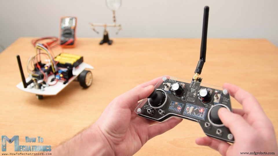
在教程中,我们将学习如何构建一个 DIY Arduino RC 发射器。很多时候,我做的项目都需要无线控制,所以我做了这个多功能的无线电控制器,几乎可以用来做任何事情。
您可以观看以下视频或阅读下面的书面教程。
概览
现在,我只需在接收器端进行一些小调整,就可以无线控制任何 Arduino 项目。该发射器还可用作任何商用遥控发射器,用于控制遥控玩具、汽车、无人机等。为此,它只需要一个简单的 Arduino 接收器,然后生成适当的信号来控制那些商业 RC 设备。
我将通过几个例子来解释这个视频中的一切是如何工作的
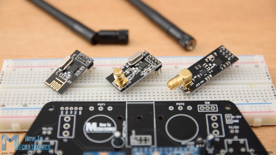
该控制器的无线电通信基于 NRF24L01 收发器模块,如果与放大天线一起使用,它可以在开放空间中具有高达 700 米的稳定范围。它具有14个通道,其中6个模拟输入和8个数字输入。
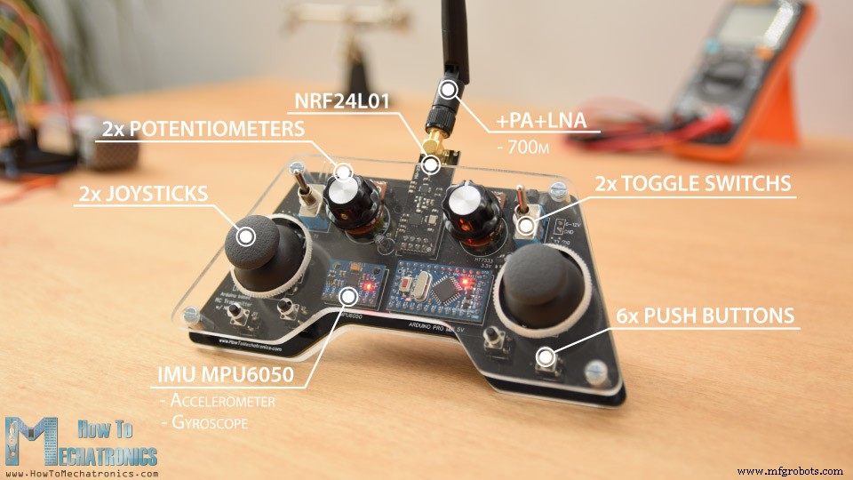
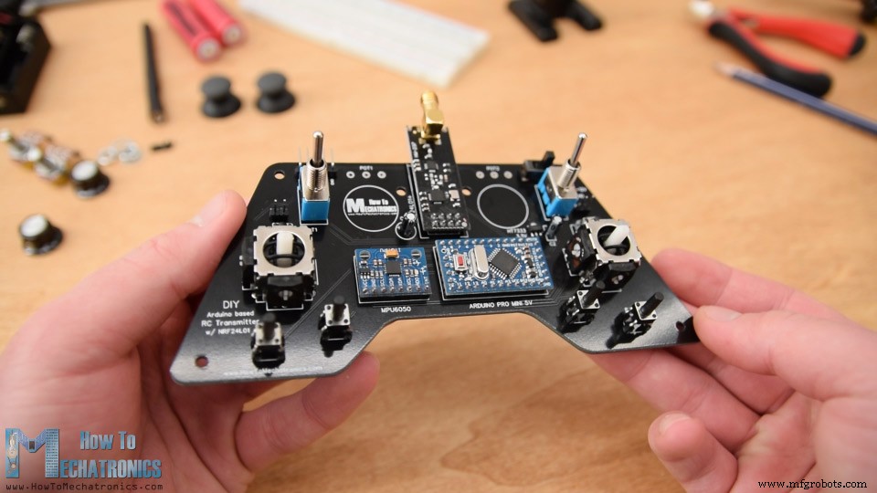
它有两个操纵杆、两个电位器、两个拨动开关、六个按钮以及一个由加速度计和陀螺仪组成的内部测量单元,也可以通过移动或倾斜控制器来控制物体。
Arduino RC发射器电路图
首先,让我们看一下电路图。这个 RC 控制器的大脑是一个 Arduino Pro Mini,它使用 2 节锂聚合物电池供电,产生约 7.4 伏的电压。我们可以将它们直接连接到 Pro Mini 的 RAW 引脚,该引脚具有将电压降低到 5V 的稳压器。请注意,Arduino Pro Mini 有两个版本,比如我的一个在 5V 下运行,另一个在 3.3V 下运行。
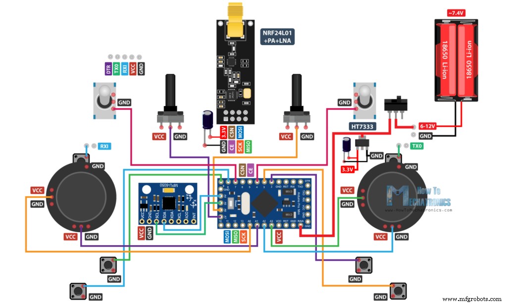
另一方面,NRF24L01 模块严格需要 3.3V,建议使用专用电源。因此,我们需要使用连接到电池的 3.3V 稳压器并将 7.4V 转换为 3.3V。另外我们需要在模块旁边使用一个去耦电容,以保持电压更稳定,这样无线电通信也会更稳定。 NRF24L01模块使用SPI协议与Arduino通信,MPU6050加速度计和陀螺仪模块使用I2C协议。
您可以从以下链接获取本 Arduino 教程所需的组件:
- NRF24L01 收发器模块…………..
- NRF24L01 + PA + LNA ……………………。
- 电位器………………………………..
- 伺服电机…………………………………………
- 拨动开关……………………………….……..
- 操纵杆………………………………………….. - 这个操纵杆带有一个分线板,所以你必须从上面拆下操纵杆
- 不带分线板的操纵杆………… Ebay
- Arduino Pro Mini……………………………….. - 您需要此板的 PCB V2 或 V3 版本
- Arduino Pro Mini 就像我使用的那个...... – PCB V1
- HT7333 3.3v稳压器……………….来自当地的电子商店——PCB V1 和 PCB V2
- AMS1117 3.3v 稳压器……………… 亚马逊 / 邦古德 /速卖通 – PCB V3
PCB设计
实际上,我最终使用了 Arduino Pro Mini 的所有模拟和数字引脚。所以现在如果我尝试使用跳线将所有东西连接在一起,那将是一团糟。因此,我使用 EasyEDA 免费在线电路设计软件设计了一个定制的 PCB。
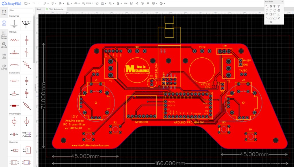
在这里,我考虑了控制器的人体工程学,并将其设计为两只手都可以轻松握住,而所有控件都在手指的范围内。我使边缘变圆并添加了一些 3 毫米的孔,以便稍后将 PCB 安装到某些东西上。我将用于对 Arduino Pro Mini 进行编程的引脚放置在控制器的顶部,以便在我们想要重新编程 Arduino 时轻松访问它们。我们还可以在这里注意到,我使用了 Arduino 的 RX 和 TX 引脚作为操纵杆按钮。然而,当我们将草图上传到 Arduino 时,这两条线需要与任何东西断开连接。因此,它们被两个引脚中断,然后可以使用简单的跳线帽轻松连接。
请注意: 确保您有正确的 Arduino Pro Mini 版本来加工 PCB 或根据它修改 PCB 设计。这是三个不同版本之间的比较照片,具体取决于您的 Arduino 和电压调节器。
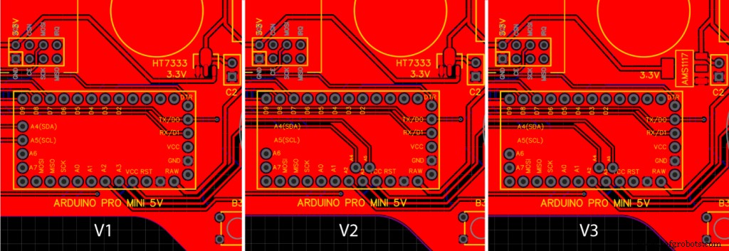
这是此 PCB 设计的项目文件的链接。这会在单独的选项卡中打开三个不同的版本,因此您可以选择您需要的版本。
所以一旦我完成了设计,我就生成了制造 PCB 所需的 Gerber 文件。
格柏文件:
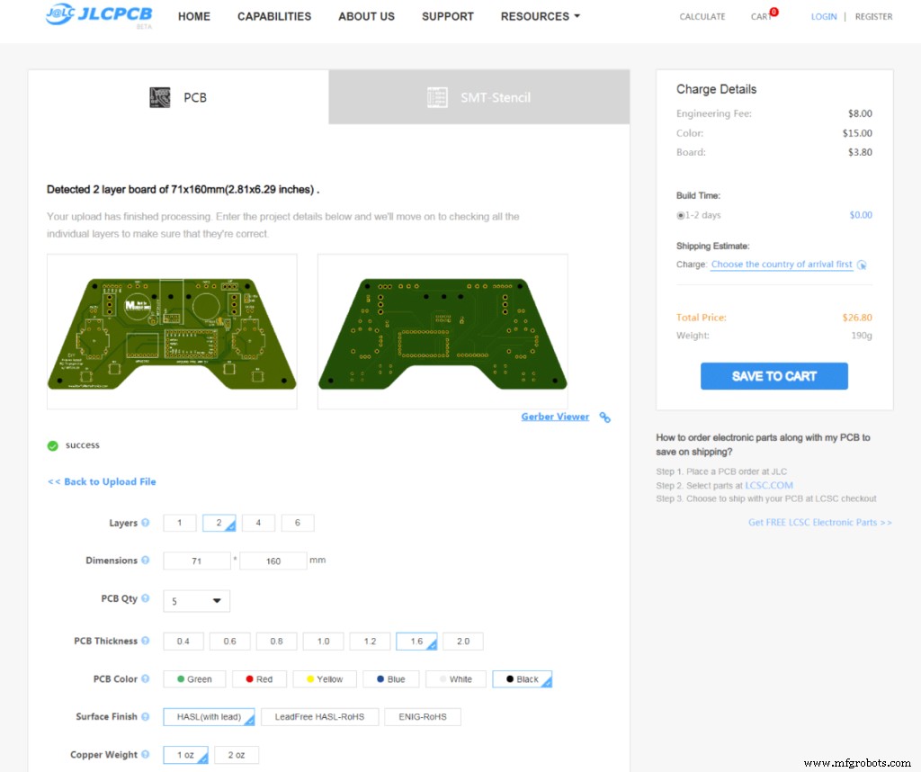
然后我从JLCPCB订购了PCB,这也是这个视频的赞助商。

在这里,我们可以简单地拖放 Gerber 文件,上传后,我们可以在 Gerber 查看器中查看我们的 PCB。如果一切正常,那么我们可以继续选择我们想要的 PCB 属性。这次我选择了PCB颜色为黑色。就是这样,现在我们可以简单地以合理的价格订购我们的 PCB。请注意,如果这是您从 JLCPCB 订购的第一个订单,您只需 2 美元即可获得多达 10 个 PCB。
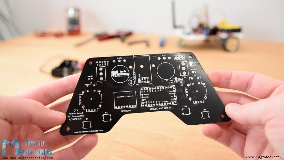
就在这里。我真的很喜欢这个印刷电路板是如何变成这种黑色的。 PCB的质量很好,一切都和设计中的一模一样。
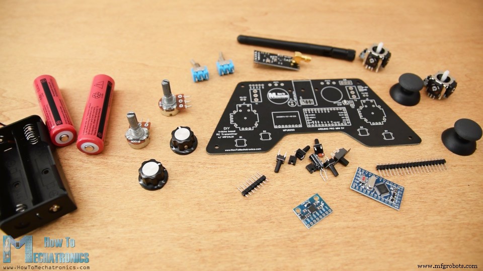
组装PCB
好的,现在我们可以继续组装 PCB。我从焊接 Arduino Pro Mini 的排针开始。一个简单而好的方法是将它们放在面包板上,这样它们在焊接时就会牢固地固定在原位。
Pro Mini 的侧面也有别针,但请注意,这些别针的位置可能因制造商而异。
对于我拥有的特定型号,我需要每侧 5 个引脚,同时将一个 GND 引脚留空,因为我使用 PCB 下方的区域来运行一些走线。我将 Arduino Pro Mini 直接焊接到 PCB 上,并切割了接头的 execs 长度。旁边是 MPU6050 加速度计和陀螺仪模块。
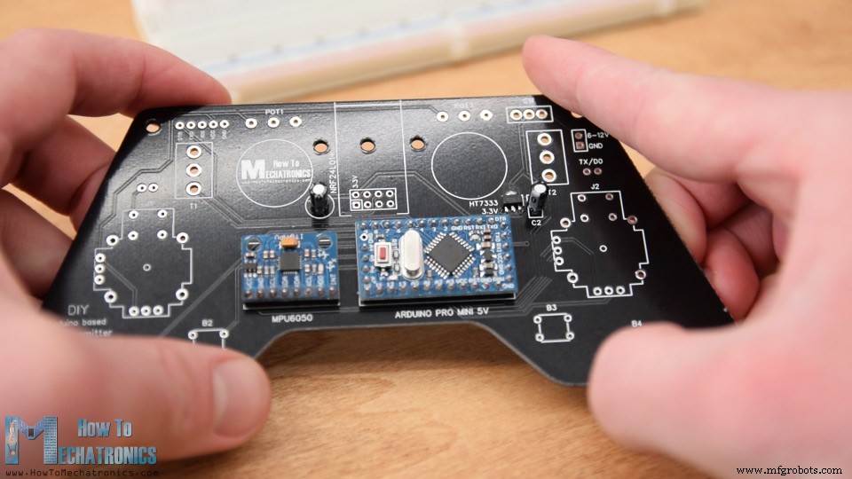
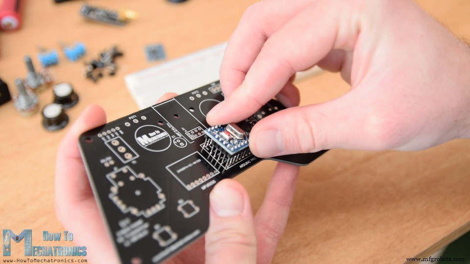
然后我焊接了 3.3V 稳压器,旁边有一个电容器,NRF24L01 模块附近还有另一个电容器。这个模块有三个不同的版本,我们可以在这里使用它们中的任何一个。
我继续使用用于编程 Arduino 的引脚、RX 和 TX 引脚、电源引脚和电源开关。
接下来要将电位器焊接到 PCB 上,我必须使用一些排针来扩展它们的引脚。
我们可以在这里注意到,我之前剪掉了旋钮的长度,这样我就可以在它们上适当地安装一些盖子。不过,我们稍后会将电位器焊接到 PCB 上。
然后我将两个拨动开关和两个操纵杆插入并焊接到位。
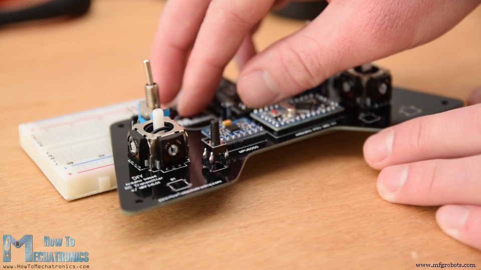
最后剩下的是焊接四个按钮。但是它们没有合适的高度,所以我再次使用排针将它们的引脚延长一点。
就是这样,我们的 PCB 现在已经准备好了,所以我们可以继续为它制作封面。因为我喜欢 PCB 的外观并且我想被人看到,所以我决定使用透明亚克力作为封面。
在这里,我有 4 毫米刻度的透明丙烯酸,目前有一个保护箔,看起来是蓝色的。盖板的想法是制作两个具有 PCB 形状的板,并将其中一个固定在 PCB 的顶部,另一个固定在 PCB 的底部。
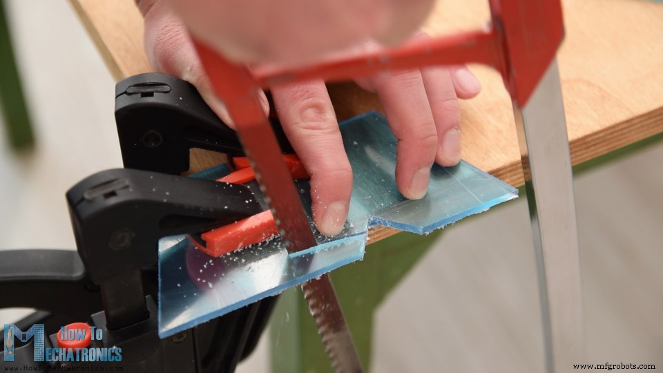
所以我标记了 PCB 形状并使用金属手锯切割了亚克力。
然后使用简单的锉刀微调亚克力的形状。这两个板出来的很好,它们与 PCB 完美匹配。

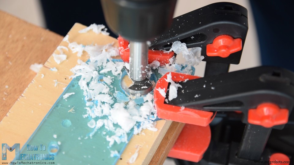
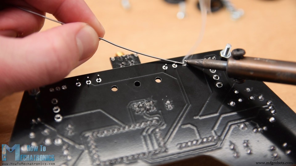
接下来,我标记了需要为组件打开开口的位置。使用 3 毫米钻头,我首先制作了 4 个孔,用于将板固定到 PCB。对于这些孔,我还制作了埋头槽,以便螺栓可以与板闪光。
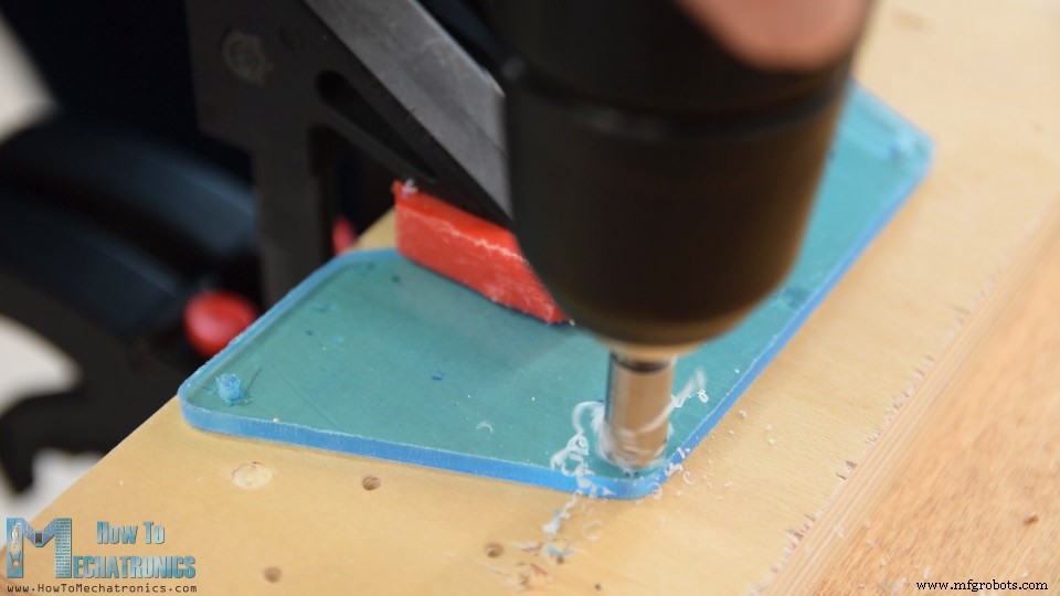
对于拨动开关和电位器的开口,我使用了 6mm 钻头,而对于操纵杆开口,我使用了 25mm Forstner 钻头。我再次使用锉刀微调了所有开口。
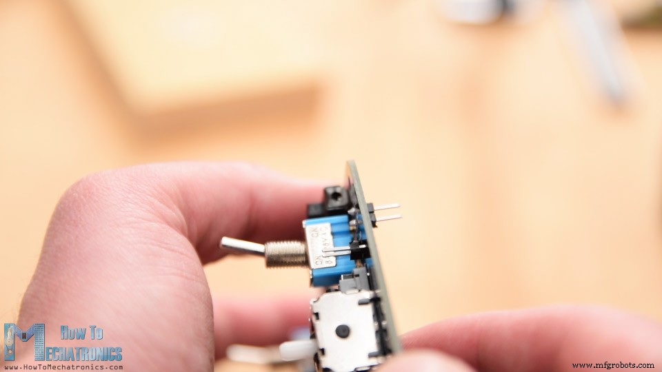
在组装盖子之前,请注意我实际上将电源的排针倒置焊接,以便可以从电池所在的背面到达。
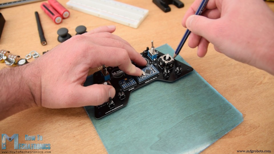
好的,现在我们可以开始组装盖子了。我从剥掉亚克力的保护膜开始,我必须承认这非常令人满意,因为亚克力现在非常干净。所以首先我将两个电位器固定在顶板上,插入 3mm 安装螺栓并将 11mm 距离环放置到位。
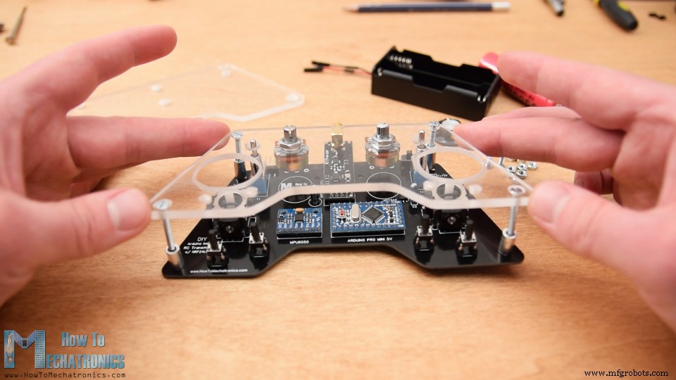
然后我小心地合并并使用一些螺栓固定顶板和 PCB。至此,我终于将电位器焊接到了 PCB 上,因为之前我并不清楚它们将被放置在什么高度。
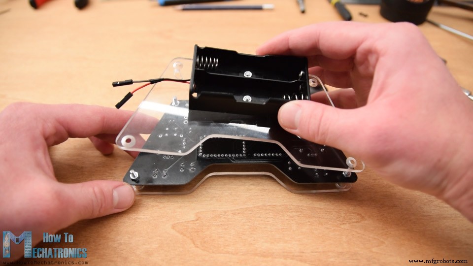
接下来在背板上,我使用 2 个螺栓连接了电池座。我使用四个安装螺栓将背板固定到 PCB 的背面,从而完成了盖板组装。
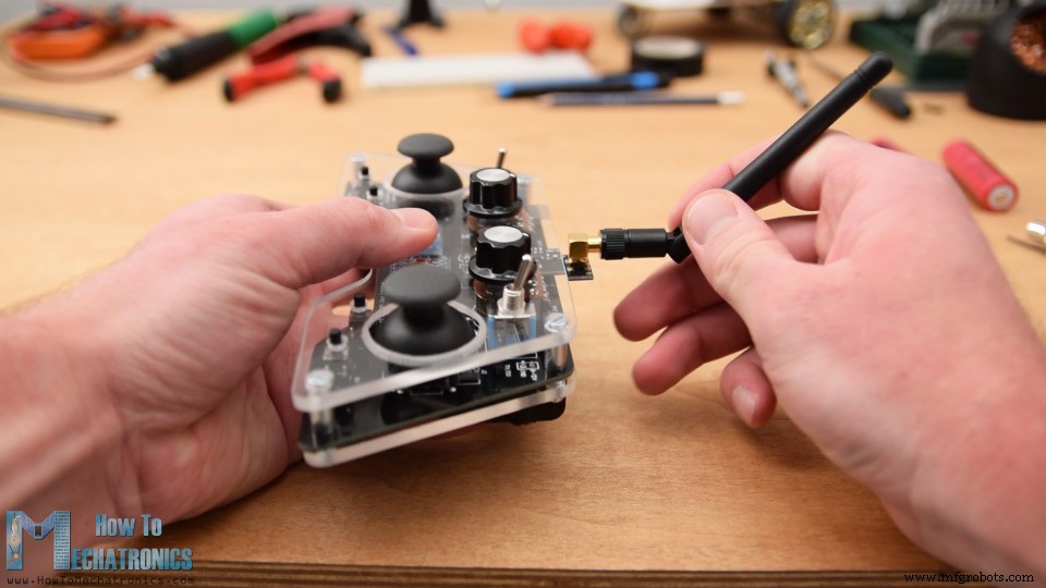
最后,我们可以将电池线连接到电源引脚,插入并固定电位器上的旋钮,插入操纵杆旋钮并将天线连接到 NRF24l01 模块。就这样,我们终于完成了 DIY Arduino RC 发射器。
现在剩下的就是对 Arduino 进行编程。为了对 Pro Mini 板进行编程,我们需要一个 USB 到串行 UART 接口,该接口可以连接到位于我们控制器顶部的编程头。
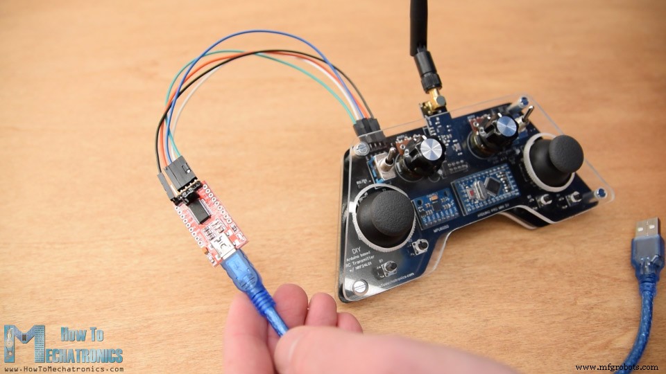
然后在Arduino IDE工具菜单中我们需要选择Arduino Pro或Pro Mini板,选择合适的处理器版本,选择端口,选择烧录方式为“USBasp”。
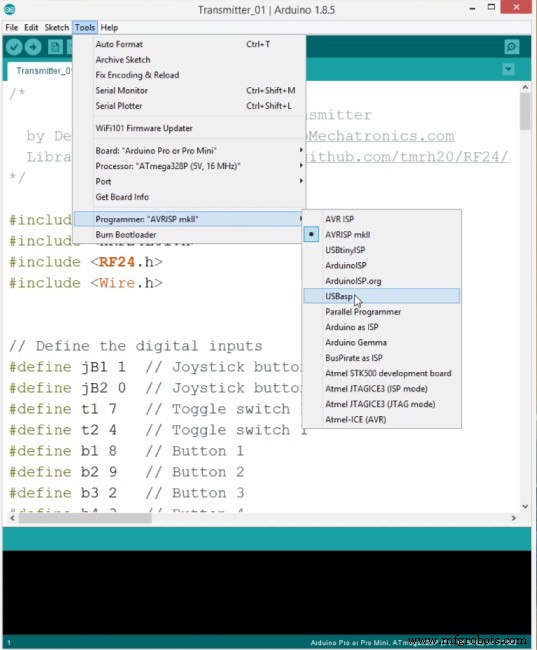
所以现在我们可以将代码上传到 Arduino。
DIY 基于 Arduino 的 RC 发射器代码
让我们解释一下发射器代码是如何工作的。所以首先我们需要包含用于无线通信的 SPI 和 RF24 库,以及用于加速度计模块的 I2C 库。然后我们需要定义数字输入,下面程序需要的一些变量,定义无线电对象和通信地址。
#include <SPI.h>
#include <nRF24L01.h>
#include <RF24.h>
#include <Wire.h>


// Define the digital inputs
#define jB1 1  // Joystick button 1
#define jB2 0  // Joystick button 2
#define t1 7   // Toggle switch 1
#define t2 4   // Toggle switch 1
#define b1 8   // Button 1
#define b2 9   // Button 2
#define b3 2   // Button 3
#define b4 3   // Button 4

const int MPU = 0x68; // MPU6050 I2C address
float AccX, AccY, AccZ;
float GyroX, GyroY, GyroZ;
float accAngleX, accAngleY, gyroAngleX, gyroAngleY;
float angleX, angleY;
float AccErrorX, AccErrorY, GyroErrorX, GyroErrorY;
float elapsedTime, currentTime, previousTime;
int c = 0;


RF24 radio(5, 6);   // nRF24L01 (CE, CSN)
const byte address[6] = "00001"; // AddressCode language: Arduino (arduino)
然后我们需要定义一个结构,我们将在其中存储控制器的 14 个输入值。这个结构的最大大小可以是 32 字节,因为这是 NRF24L01 缓冲区的限制或模块一次可以发送的数据量。
/ Max size of this struct is 32 bytes - NRF24L01 buffer limit
struct Data_Package {
  byte j1PotX;
  byte j1PotY;
  byte j1Button;
  byte j2PotX;
  byte j2PotY;
  byte j2Button;
  byte pot1;
  byte pot2;
  byte tSwitch1;
  byte tSwitch2;
  byte button1;
  byte button2;
  byte button3;
  byte button4;
};

Data_Package data; //Create a variable with the above structureCode language: Arduino (arduino)
在设置部分我们需要初始化 MPU6050 模块,我们还可以计算 IMU 误差,这个值是稍后在计算模块正确角度时使用的值。
void initialize_MPU6050() {
  Wire.begin();                      // Initialize comunication
  Wire.beginTransmission(MPU);       // Start communication with MPU6050 // MPU=0x68
  Wire.write(0x6B);                  // Talk to the register 6B
  Wire.write(0x00);                  // Make reset - place a 0 into the 6B register
  Wire.endTransmission(true);        //end the transmission
  // Configure Accelerometer
  Wire.beginTransmission(MPU);
  Wire.write(0x1C);                  //Talk to the ACCEL_CONFIG register
  Wire.write(0x10);                  //Set the register bits as 00010000 (+/- 8g full scale range)
  Wire.endTransmission(true);
  // Configure Gyro
  Wire.beginTransmission(MPU);
  Wire.write(0x1B);                   // Talk to the GYRO_CONFIG register (1B hex)
  Wire.write(0x10);                   // Set the register bits as 00010000 (1000dps full scale)
  Wire.endTransmission(true);
}Code language: Arduino (arduino)
您可以在此处找到 MEMS 加速度计和陀螺仪工作原理的更多详细信息。 MPU6050 的专用教程即将推出。
然后我们需要初始化无线电通信,激活所有数字输入的Arduino内部上拉电阻,并为所有变量设置初始默认值。
// Define the radio communication
  radio.begin();
  radio.openWritingPipe(address);
  radio.setAutoAck(false);
  radio.setDataRate(RF24_250KBPS);
  radio.setPALevel(RF24_PA_LOW);

  // Activate the Arduino internal pull-up resistors
  pinMode(jB1, INPUT_PULLUP);
  pinMode(jB2, INPUT_PULLUP);
  pinMode(t1, INPUT_PULLUP);
  pinMode(t2, INPUT_PULLUP);
  pinMode(b1, INPUT_PULLUP);
  pinMode(b2, INPUT_PULLUP);
  pinMode(b3, INPUT_PULLUP);
  pinMode(b4, INPUT_PULLUP);Code language: Arduino (arduino)
在循环部分,首先读取所有模拟输入,将它们的值从 0 到 1023 映射为从 0 到 255 的字节值,因为我们已经将结构中的变量定义为字节。每个输入都存储在结构中的特定数据变量中。
// Read all analog inputs and map them to one Byte value
  data.j1PotX = map(analogRead(A1), 0, 1023, 0, 255); // Convert the analog read value from 0 to 1023 into a BYTE value from 0 to 255
  data.j1PotY = map(analogRead(A0), 0, 1023, 0, 255);
  data.j2PotX = map(analogRead(A2), 0, 1023, 0, 255);
  data.j2PotY = map(analogRead(A3), 0, 1023, 0, 255);
  data.pot1 = map(analogRead(A7), 0, 1023, 0, 255);
  data.pot2 = map(analogRead(A6), 0, 1023, 0, 255);Code language: Arduino (arduino)
我们只需要注意,因为我们使用上拉电阻,所以按下按钮时数字引脚读数为 0。
// Read all digital inputs
  data.j1Button = digitalRead(jB1);
  data.j2Button = digitalRead(jB2);
  data.tSwitch2 = digitalRead(t2);
  data.button1 = digitalRead(b1);
  data.button2 = digitalRead(b2);
  data.button3 = digitalRead(b3);
  data.button4 = digitalRead(b4);Code language: Arduino (arduino)
所以使用 radio.write() 函数,我们简单地将所有 14 个通道的值发送到接收器。
// Send the whole data from the structure to the receiver
  radio.write(&data, sizeof(Data_Package));Code language: Arduino (arduino)
如果拨动开关 1 被打开,那么我们使用加速度计和陀螺仪数据来代替控制。
if (digitalRead(t1) == 0) {
    read_IMU();    // Use MPU6050 instead of Joystick 1 for controling left, right, forward and backward movements
  }Code language: Arduino (arduino)
因此,我们使用从 IMU 获得的角度值代替操纵杆 1 的 X 和 Y 值,我们之前将它们从 -90 到 +90 度的值适当地转换为 0 到 255 的字节值。
// Map the angle values from -90deg to +90 deg into values from 0 to 255, like the values we are getting from the Joystick
  data.j1PotX = map(angleX, -90, +90, 255, 0);
  data.j1PotY = map(angleY, -90, +90, 0, 255);Code language: Arduino (arduino)
这就是发射器代码的方式,最重要的是定义无线电通信并将数据发送到接收器。
这是这个 DIY Arduino RC 发射器的完整 Arduino 代码:
/*
        DIY Arduino based RC Transmitter
  by Dejan Nedelkovski, www.HowToMechatronics.com
  Library: TMRh20/RF24, https://github.com/tmrh20/RF24/
*/

#include <SPI.h>
#include <nRF24L01.h>
#include <RF24.h>
#include <Wire.h>


// Define the digital inputs
#define jB1 1  // Joystick button 1
#define jB2 0  // Joystick button 2
#define t1 7   // Toggle switch 1
#define t2 4   // Toggle switch 1
#define b1 8   // Button 1
#define b2 9   // Button 2
#define b3 2   // Button 3
#define b4 3   // Button 4

const int MPU = 0x68; // MPU6050 I2C address
float AccX, AccY, AccZ;
float GyroX, GyroY, GyroZ;
float accAngleX, accAngleY, gyroAngleX, gyroAngleY;
float angleX, angleY;
float AccErrorX, AccErrorY, GyroErrorX, GyroErrorY;
float elapsedTime, currentTime, previousTime;
int c = 0;


RF24 radio(5, 6);   // nRF24L01 (CE, CSN)
const byte address[6] = "00001"; // Address

// Max size of this struct is 32 bytes - NRF24L01 buffer limit
struct Data_Package {
  byte j1PotX;
  byte j1PotY;
  byte j1Button;
  byte j2PotX;
  byte j2PotY;
  byte j2Button;
  byte pot1;
  byte pot2;
  byte tSwitch1;
  byte tSwitch2;
  byte button1;
  byte button2;
  byte button3;
  byte button4;
};

Data_Package data; //Create a variable with the above structure

void setup() {
  Serial.begin(9600);

  // Initialize interface to the MPU6050
  initialize_MPU6050();

  // Call this function if you need to get the IMU error values for your module
  //calculate_IMU_error();

  // Define the radio communication
  radio.begin();
  radio.openWritingPipe(address);
  radio.setAutoAck(false);
  radio.setDataRate(RF24_250KBPS);
  radio.setPALevel(RF24_PA_LOW);

  // Activate the Arduino internal pull-up resistors
  pinMode(jB1, INPUT_PULLUP);
  pinMode(jB2, INPUT_PULLUP);
  pinMode(t1, INPUT_PULLUP);
  pinMode(t2, INPUT_PULLUP);
  pinMode(b1, INPUT_PULLUP);
  pinMode(b2, INPUT_PULLUP);
  pinMode(b3, INPUT_PULLUP);
  pinMode(b4, INPUT_PULLUP);

  // Set initial default values
  data.j1PotX = 127; // Values from 0 to 255. When Joystick is in resting position, the value is in the middle, or 127. We actually map the pot value from 0 to 1023 to 0 to 255 because that's one BYTE value
  data.j1PotY = 127;
  data.j2PotX = 127;
  data.j2PotY = 127;
  data.j1Button = 1;
  data.j2Button = 1;
  data.pot1 = 1;
  data.pot2 = 1;
  data.tSwitch1 = 1;
  data.tSwitch2 = 1;
  data.button1 = 1;
  data.button2 = 1;
  data.button3 = 1;
  data.button4 = 1;
}
void loop() {
  // Read all analog inputs and map them to one Byte value
  data.j1PotX = map(analogRead(A1), 0, 1023, 0, 255); // Convert the analog read value from 0 to 1023 into a BYTE value from 0 to 255
  data.j1PotY = map(analogRead(A0), 0, 1023, 0, 255);
  data.j2PotX = map(analogRead(A2), 0, 1023, 0, 255);
  data.j2PotY = map(analogRead(A3), 0, 1023, 0, 255);
  data.pot1 = map(analogRead(A7), 0, 1023, 0, 255);
  data.pot2 = map(analogRead(A6), 0, 1023, 0, 255);
  // Read all digital inputs
  data.j1Button = digitalRead(jB1);
  data.j2Button = digitalRead(jB2);
  data.tSwitch2 = digitalRead(t2);
  data.button1 = digitalRead(b1);
  data.button2 = digitalRead(b2);
  data.button3 = digitalRead(b3);
  data.button4 = digitalRead(b4);
  // If toggle switch 1 is switched on
  if (digitalRead(t1) == 0) {
    read_IMU();    // Use MPU6050 instead of Joystick 1 for controling left, right, forward and backward movements
  }
  // Send the whole data from the structure to the receiver
  radio.write(&data, sizeof(Data_Package));
}

void initialize_MPU6050() {
  Wire.begin();                      // Initialize comunication
  Wire.beginTransmission(MPU);       // Start communication with MPU6050 // MPU=0x68
  Wire.write(0x6B);                  // Talk to the register 6B
  Wire.write(0x00);                  // Make reset - place a 0 into the 6B register
  Wire.endTransmission(true);        //end the transmission
  // Configure Accelerometer
  Wire.beginTransmission(MPU);
  Wire.write(0x1C);                  //Talk to the ACCEL_CONFIG register
  Wire.write(0x10);                  //Set the register bits as 00010000 (+/- 8g full scale range)
  Wire.endTransmission(true);
  // Configure Gyro
  Wire.beginTransmission(MPU);
  Wire.write(0x1B);                   // Talk to the GYRO_CONFIG register (1B hex)
  Wire.write(0x10);                   // Set the register bits as 00010000 (1000dps full scale)
  Wire.endTransmission(true);
}

void calculate_IMU_error() {
  // We can call this funtion in the setup section to calculate the accelerometer and gury data error. From here we will get the error values used in the above equations printed on the Serial Monitor.
  // Note that we should place the IMU flat in order to get the proper values, so that we then can the correct values
  // Read accelerometer values 200 times
  while (c < 200) {
    Wire.beginTransmission(MPU);
    Wire.write(0x3B);
    Wire.endTransmission(false);
    Wire.requestFrom(MPU, 6, true);
    AccX = (Wire.read() << 8 | Wire.read()) / 4096.0 ;
    AccY = (Wire.read() << 8 | Wire.read()) / 4096.0 ;
    AccZ = (Wire.read() << 8 | Wire.read()) / 4096.0 ;
    // Sum all readings
    AccErrorX = AccErrorX + ((atan((AccY) / sqrt(pow((AccX), 2) + pow((AccZ), 2))) * 180 / PI));
    AccErrorY = AccErrorY + ((atan(-1 * (AccX) / sqrt(pow((AccY), 2) + pow((AccZ), 2))) * 180 / PI));
    c++;
  }
  //Divide the sum by 200 to get the error value
  AccErrorX = AccErrorX / 200;
  AccErrorY = AccErrorY / 200;
  c = 0;
  // Read gyro values 200 times
  while (c < 200) {
    Wire.beginTransmission(MPU);
    Wire.write(0x43);
    Wire.endTransmission(false);
    Wire.requestFrom(MPU, 4, true);
    GyroX = Wire.read() << 8 | Wire.read();
    GyroY = Wire.read() << 8 | Wire.read();
    // Sum all readings
    GyroErrorX = GyroErrorX + (GyroX / 32.8);
    GyroErrorY = GyroErrorY + (GyroY / 32.8);
    c++;
  }
  //Divide the sum by 200 to get the error value
  GyroErrorX = GyroErrorX / 200;
  GyroErrorY = GyroErrorY / 200;
  // Print the error values on the Serial Monitor
  Serial.print("AccErrorX: ");
  Serial.println(AccErrorX);
  Serial.print("AccErrorY: ");
  Serial.println(AccErrorY);
  Serial.print("GyroErrorX: ");
  Serial.println(GyroErrorX);
  Serial.print("GyroErrorY: ");
  Serial.println(GyroErrorY);
}

void read_IMU() {
  // === Read acceleromter data === //
  Wire.beginTransmission(MPU);
  Wire.write(0x3B); // Start with register 0x3B (ACCEL_XOUT_H)
  Wire.endTransmission(false);
  Wire.requestFrom(MPU, 6, true); // Read 6 registers total, each axis value is stored in 2 registers
  //For a range of +-8g, we need to divide the raw values by 4096, according to the datasheet
  AccX = (Wire.read() << 8 | Wire.read()) / 4096.0; // X-axis value
  AccY = (Wire.read() << 8 | Wire.read()) / 4096.0; // Y-axis value
  AccZ = (Wire.read() << 8 | Wire.read()) / 4096.0; // Z-axis value

  // Calculating angle values using
  accAngleX = (atan(AccY / sqrt(pow(AccX, 2) + pow(AccZ, 2))) * 180 / PI) + 1.15; // AccErrorX ~(-1.15) See the calculate_IMU_error()custom function for more details
  accAngleY = (atan(-1 * AccX / sqrt(pow(AccY, 2) + pow(AccZ, 2))) * 180 / PI) - 0.52; // AccErrorX ~(0.5)

  // === Read gyro data === //
  previousTime = currentTime;        // Previous time is stored before the actual time read
  currentTime = millis();            // Current time actual time read
  elapsedTime = (currentTime - previousTime) / 1000;   // Divide by 1000 to get seconds
  Wire.beginTransmission(MPU);
  Wire.write(0x43); // Gyro data first register address 0x43
  Wire.endTransmission(false);
  Wire.requestFrom(MPU, 4, true); // Read 4 registers total, each axis value is stored in 2 registers
  GyroX = (Wire.read() << 8 | Wire.read()) / 32.8; // For a 1000dps range we have to divide first the raw value by 32.8, according to the datasheet
  GyroY = (Wire.read() << 8 | Wire.read()) / 32.8;
  GyroX = GyroX + 1.85; //// GyroErrorX ~(-1.85)
  GyroY = GyroY - 0.15; // GyroErrorY ~(0.15)
  // Currently the raw values are in degrees per seconds, deg/s, so we need to multiply by sendonds (s) to get the angle in degrees
  gyroAngleX = GyroX * elapsedTime;
  gyroAngleY = GyroY * elapsedTime;

  // Complementary filter - combine acceleromter and gyro angle values
  angleX = 0.98 * (angleX + gyroAngleX) + 0.02 * accAngleX;
  angleY = 0.98 * (angleY + gyroAngleY) + 0.02 * accAngleY;
  // Map the angle values from -90deg to +90 deg into values from 0 to 255, like the values we are getting from the Joystick
  data.j1PotX = map(angleX, -90, +90, 255, 0);
  data.j1PotY = map(angleY, -90, +90, 0, 255);
}Code language: Arduino (arduino)
接收方代码
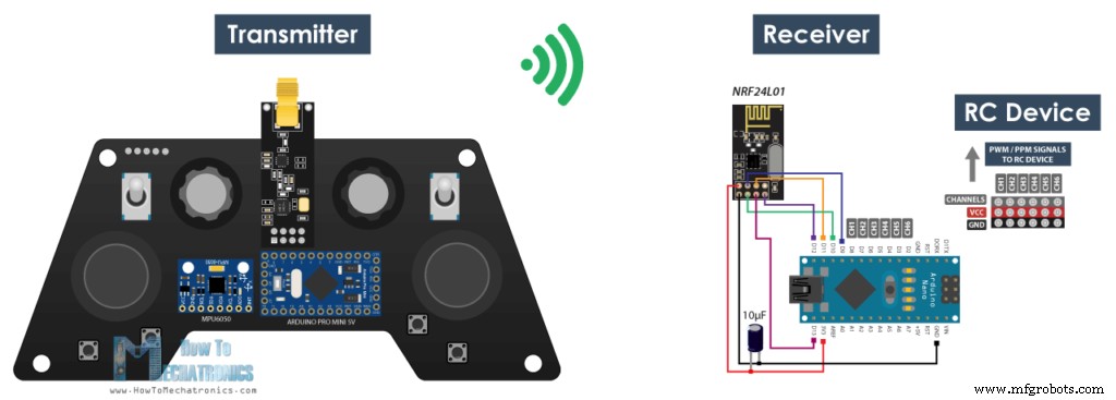
现在让我们看看如何接收这些数据。这是一个简单的 Arduino 和 NRF24L01 接收器原理图。当然,您可以使用任何其他 Arduino 板。
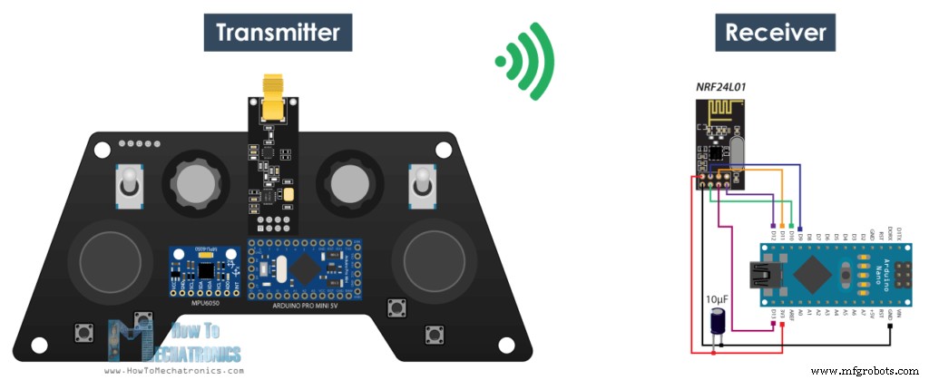
这是一个简单的接收器代码,我们将在其中接收数据并将其简单地打印在串行监视器上,以便我们知道通信正常工作。同样,我们需要包含 RF24 库并以与发送器代码相同的方式定义对象和结构。在设置部分定义无线电通信时,我们需要使用与发射器相同的设置,并使用 radio.startListening() 函数将模块设置为接收器。
/*
    DIY Arduino based RC Transmitter Project
              == Receiver Code ==

  by Dejan Nedelkovski, www.HowToMechatronics.com
  Library: TMRh20/RF24, https://github.com/tmrh20/RF24/
*/
#include <SPI.h>
#include <nRF24L01.h>
#include <RF24.h>
RF24 radio(10, 9);   // nRF24L01 (CE, CSN)
const byte address[6] = "00001";

unsigned long lastReceiveTime = 0;
unsigned long currentTime = 0;

// Max size of this struct is 32 bytes - NRF24L01 buffer limit
struct Data_Package {
  byte j1PotX;
  byte j1PotY;
  byte j1Button;
  byte j2PotX;
  byte j2PotY;
  byte j2Button;
  byte pot1;
  byte pot2;
  byte tSwitch1;
  byte tSwitch2;
  byte button1;
  byte button2;
  byte button3;
  byte button4;
};

Data_Package data; //Create a variable with the above structure

void setup() {
  Serial.begin(9600);
  radio.begin();
  radio.openReadingPipe(0, address);
  radio.setAutoAck(false);
  radio.setDataRate(RF24_250KBPS);
  radio.setPALevel(RF24_PA_LOW);
  radio.startListening(); //  Set the module as receiver
  resetData();
}
void loop() {
  // Check whether there is data to be received
  if (radio.available()) {
    radio.read(&data, sizeof(Data_Package)); // Read the whole data and store it into the 'data' structure
    lastReceiveTime = millis(); // At this moment we have received the data
  }
  // Check whether we keep receving data, or we have a connection between the two modules
  currentTime = millis();
  if ( currentTime - lastReceiveTime > 1000 ) { // If current time is more then 1 second since we have recived the last data, that means we have lost connection
    resetData(); // If connection is lost, reset the data. It prevents unwanted behavior, for example if a drone has a throttle up and we lose connection, it can keep flying unless we reset the values
  }
  // Print the data in the Serial Monitor
  Serial.print("j1PotX: ");
  Serial.print(data.j1PotX);
  Serial.print("; j1PotY: ");
  Serial.print(data.j1PotY);
  Serial.print("; button1: ");
  Serial.print(data.button1);
  Serial.print("; j2PotX: ");
  Serial.println(data.j2PotX);
}

void resetData() {
  // Reset the values when there is no radio connection - Set initial default values
  data.j1PotX = 127;
  data.j1PotY = 127;
  data.j2PotX = 127;
  data.j2PotY = 127;
  data.j1Button = 1;
  data.j2Button = 1;
  data.pot1 = 1;
  data.pot2 = 1;
  data.tSwitch1 = 1;
  data.tSwitch2 = 1;
  data.button1 = 1;
  data.button2 = 1;
  data.button3 = 1;
  data.button4 = 1;
}Code language: Arduino (arduino)
在使用 available() 函数的主循环中,我们检查是否有传入数据。如果为真,我们只需读取数据并将其存储到结构的变量中。现在我们可以在串口监视器上打印数据来检查传输是否正常。同样使用 millis() 函数和 if 语句,我们检查我们是否继续接收数据,或者我们是否在超过 1 秒的时间内没有接收到数据,然后我们将变量重置为其默认值。我们使用它来防止不必要的行为,例如,如果无人机加速并且我们失去连接,除非我们重置值,否则它会继续飞走。
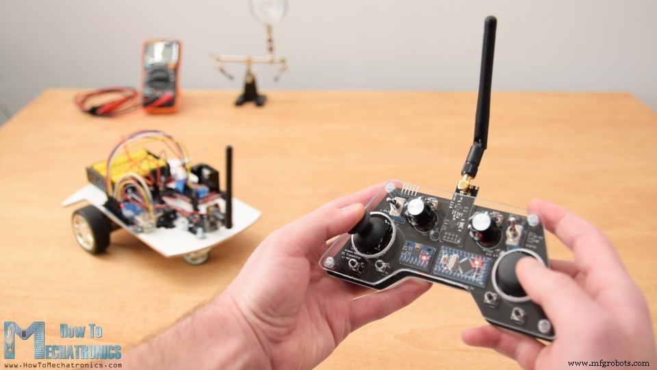
就是这样了。现在我们可以为任何 Arduino 项目实现这种接收数据的方法。例如,这里是我之前的视频中控制 Arduino 机器人汽车的代码。
作为这个项目的更新,我制作了一个基于 Arduino 的专用 RC 接收器。同样,它基于 Arduino Pro 迷你板,它有几个现成的伺服器和 ESC 连接,放置在紧凑的 PCB 上。
使用 RC 发射器的 Arduino 机器人汽车无线控制
Arduino代码:
在这里,我们需要定义库、结构和无线电通信,如前所述。然后在主循环中,我们只需要读取传入的数据并将其中的任何一个用于我们想要的任何内容。在这种情况下,我使用操纵杆 1 的值来驾驶汽车。
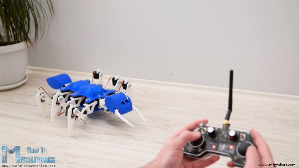
Arduino Ant 机器人/使用 Arduino RC 发射器的六足机器人控制
Arduino代码:
以与我之前视频中制作的 Arduino Ant 机器人完全相同的方式,使用这个 Arduino RC 发射器进行无线控制。我们只需要读取数据,并根据它执行相应的功能,如前进、左、右、咬、攻击等。
ESC 和伺服控制使用 RC 发射器
最后,让我们看看这款发射器如何用于控制商用RC设备。
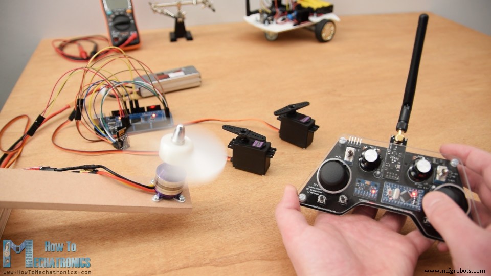
通常对于这些设备,我们需要控制它们的伺服系统或无刷电机。因此,在接收到来自发射器的数据后,为了控制伺服,我们只需使用 Arduino 伺服库并使用 0 到 180 度之间的值。对于使用 ESC 控制无刷电机,我们可以再次使用伺服库来生成用于控制 ESC 的 50Hz PWM 信号。通过将占空比从 1000 微秒变化到 2000 微秒,我们将电机的 RPM 从零控制到最大值。不过,在我的下一个教程中,更多关于使用 ESC 控制无刷电机的内容。
请注意,我们实际上无法将标准 RC 接收器系统与此 NRF24L01 2.4GHz 系统绑定。相反,我们需要修改或创建我们自己的由 Arduino 和 NRF24L01 模块组成的接收器。从那里我们可以生成适当的 PWM 或 PPM 信号来控制 RC 设备。
/*
    DIY Arduino based RC Transmitter Project
   == Receiver Code - ESC and Servo Control ==

  by Dejan Nedelkovski, www.HowToMechatronics.com
  Library: TMRh20/RF24, https://github.com/tmrh20/RF24/
*/
#include <SPI.h>
#include <nRF24L01.h>
#include <RF24.h>
#include <Servo.h>

RF24 radio(10, 9);   // nRF24L01 (CE, CSN)
const byte address[6] = "00001";

unsigned long lastReceiveTime = 0;
unsigned long currentTime = 0;

Servo esc;  // create servo object to control the ESC
Servo servo1;
Servo servo2;
int escValue, servo1Value, servo2Value;

// Max size of this struct is 32 bytes - NRF24L01 buffer limit
struct Data_Package {
  byte j1PotX;
  byte j1PotY;
  byte j1Button;
  byte j2PotX;
  byte j2PotY;
  byte j2Button;
  byte pot1;
  byte pot2;
  byte tSwitch1;
  byte tSwitch2;
  byte button1;
  byte button2;
  byte button3;
  byte button4;
};

Data_Package data; //Create a variable with the above structure

void setup() {
  Serial.begin(9600);
  radio.begin();
  radio.openReadingPipe(0, address);
  radio.setAutoAck(false);
  radio.setDataRate(RF24_250KBPS);
  radio.setPALevel(RF24_PA_LOW);
  radio.startListening(); //  Set the module as receiver
  resetData();
  esc.attach(9);
  servo1.attach(3);
  servo2.attach(4);
}
void loop() {
  // Check whether we keep receving data, or we have a connection between the two modules
  currentTime = millis();
  if ( currentTime - lastReceiveTime > 1000 ) { // If current time is more then 1 second since we have recived the last data, that means we have lost connection
    resetData(); // If connection is lost, reset the data. It prevents unwanted behavior, for example if a drone jas a throttle up, if we lose connection it can keep flying away if we dont reset the function
  }
  // Check whether there is data to be received
  if (radio.available()) {
    radio.read(&data, sizeof(Data_Package)); // Read the whole data and store it into the 'data' structure
    lastReceiveTime = millis(); // At this moment we have received the data
  }
  // Controlling servos
  servo1Value = map(data.j2PotX, 0, 255, 0, 180);
  servo2Value = map(data.j2PotY, 0, 255, 0, 180);
  servo1.write(servo1Value);
  servo2.write(servo2Value);
  // Controlling brushless motor with ESC
  escValue = map(data.pot1, 0, 255, 1000, 2000); // Map the receiving value form 0 to 255 to 0 1000 to 2000, values used for controlling ESCs
  esc.writeMicroseconds(escValue); // Send the PWM control singal to the ESC
}

void resetData() {
  // Reset the values when there is no radio connection - Set initial default values
  data.j1PotX = 127;
  data.j1PotY = 127;
  data.j2PotX = 127;
  data.j2PotY = 127;
  data.j1Button = 1;
  data.j2Button = 1;
  data.pot1 = 1;
  data.pot2 = 1;
  data.tSwitch1 = 1;
  data.tSwitch2 = 1;
  data.button1 = 1;
  data.button2 = 1;
  data.button3 = 1;
  data.button4 = 1;
}Code language: Arduino (arduino)
就是这样了。我希望你喜欢这个视频并学到了一些新东西。随时在下面的评论部分提出任何问题,并查看我的 Arduino 项目收藏。
制造工艺