

如何找到适合电气布线安装的电缆和电线尺寸? – 英制和公制示例
如何确定电线电缆安装的合适尺寸?
以下分步指南将向您展示如何通过已解决的示例(英式或英语和SI System,即英制和公制)。
请记住,在为电气安装确定电线尺寸时,选择合适的电线尺寸非常重要。对于具有大电流的较大负载,如果电线尺寸不合适,可能会造成混乱,从而导致电气设备故障、危险火灾和严重伤害。
电缆电压降
我们知道所有导体、电线和电缆(超导体除外)都有一定的电阻。
这个电阻与导体的长度成正比,与导体的直径成反比,即
R ∝ L/a … [电阻定律 R =ρ (L/a)]
当电流流过导体时,该导体中会出现电压降。一般来说,对于小长度的导体,压降可以忽略不计,但对于直径较小、长度较长的导体,我们必须考虑到相当大的压降,以进行正确的布线安装和未来的负载管理。
根据IEEE规则B-23 ,在电源端子和安装之间的任何点,压降不应超过所提供(电源)电压的 2.5% .
相关帖子:
- 如何找到合适尺寸的断路器?断路器计算器和示例
- 如何找到开关、插头、插座和插座的电压和电流额定值
- LT &HT Motors 的电缆尺寸如何计算?

示例:
如果供电电压为220V AC,则允许压降值应为;
- 允许压降 =220 x (2.5/100) =5.5V
同理,如果供电电压为120V AC,则允许压降不超过3V(120V x 2.5%)。
在电气布线电路中,从配电板到不同的子电路和最终子电路也会发生电压降,但是对于子电路和最终子电路,电压降的值应该是允许电压降的一半(即上面计算的 5.5V 的 2.75V)
通常,表格中的电压降用每米安培数 (A/m) 来描述 例如承载一安培电流的一米电缆的电压降是多少?
有两种方法可以定义电缆中的电压降 我们将在下面讨论。
在 SI (系统国际和公制 ) 电压降用 每米安培 (A/m) 来描述 .
在 FPS(英尺磅系统) 电压降按长度描述,即 100 英尺。
- 更新 :现在您也可以使用以下电子计算器来计算美国线规中的电压降和线径 系统。
- 电线电缆尺寸计算器(铜和铝)
- AWG 电线和电缆尺寸计算器
- 电线电缆电压降计算器
适合电缆和电线尺寸的表格和图表
以下是您应遵循的重要表格,以确定电气布线安装的适当电缆尺寸。
点击图片放大
点击图片放大
 点击图片放大
点击图片放大
 点击图片放大
如何找出电缆中的电压降?
要查找电缆中的电压降,请按照以下简单步骤操作。
- 首先,找出允许的最大电压降。
- 现在,求负载电流。
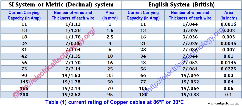
- 现在,根据负载电流,从表 1 中选择合适的电缆(其额定电流应最接近计算的负载电流)。
- 从表 1 中,根据额定电流找出以米或 100 英尺为单位的电压降(您喜欢什么系统)。
(保持冷静:)在我们解决的整个电气安装布线示例中,我们将遵循两种方法和系统来查找电压降(以米和 100 英尺为单位)。
- 现在,借助以下公式,根据额定电流计算出接线电路实际长度的电压降 .
(电路的实际长度 x 1m 的压降)/100 ===> 求每米的压降。
(电路的实际长度 x 压降for 100ft) /100 ===> 求 100 英尺内的电压降。
- 现在将计算得到的电压降乘以负载系数,其中;
负载系数=电缆所要承受的负载电流/表中给出的电缆额定电流。
- 这是负载电流流过电缆时电缆中的压降值。
- 如果计算的压降值小于步骤(1)中计算的值(最大允许压降),则选择的电缆尺寸合适
- 如果计算的压降值大于步骤(1)中计算的值(最大允许压降),则计算下一条(更大的)电缆的压降,以此类推,直到计算出的电压值降变得小于步骤 (1) 中计算的最大允许电压降。
如何确定给定负载的合适电缆和电线尺寸?
以下是已解决的示例,展示了如何为给定负载找到合适的电缆尺寸。
对于给定的负载,可以借助不同的表格找到电缆尺寸,但我们应该牢记并遵守有关电压降的规则。
确定给定负载的电缆尺寸,请考虑以下规则。
对于给定的负载,除了电流的已知值外,应该有 20% 的额外电流范围用于额外、未来或紧急需要。
从电表到配电板,压降应1.25% 对于最终子电路,压降不应超过2.5% 电源电压。
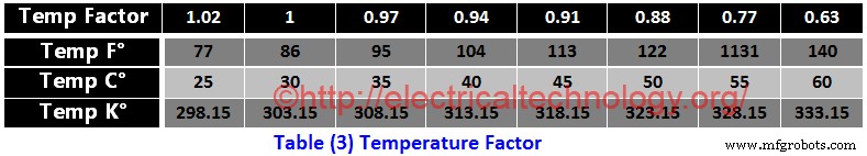
考虑温度变化,需要时使用温度因子(表3)
另外,在计算电缆尺寸时要考虑负载系数
在确定电缆尺寸时,请考虑布线系统,即在开放式布线系统中,温度会较低,但在导管布线中,由于没有空气,温度会升高。
- 注意:在为电线安装选择合适尺寸的电缆时,请记住电线安装中的多样性因素
解决的正确电线电缆尺寸示例
以下是确定电气布线安装电缆的正确尺寸的示例,这将使您易于理解“如何确定给定电缆的正确尺寸”的方法加载”。
示例 1……(英制、英制或英制)
对于建筑物中的电气布线安装,总负载为 4.5kW,从电能表到子电路配电板的电缆总长度为 35 英尺。电源电压为 220V,温度为 40°C (104°F)。如果接线安装在导管中,请找到从电能表到子电路的最合适尺寸的电缆。
解决办法:-
- 总负载 =4.5kW =4.5 x1000W =4500W
- 20% 额外负载 =4500 x (20/100) =900W
- 总负载 =4500W + 900W =5400W
- 总电流 =I =P/V =5400W /220V =24.5A
现在为24.5A的负载电流选择电缆尺寸 (来自表 1)为 7/0.036(28 安培)。这意味着我们可以根据表1使用7/0.036电缆。
现在检查选定的 (7/0.036) 电缆与表 3 中的温度系数,因此在 40°C (104°F) 时温度系数为 0.94(在表 3 中) (7/0.036) 的载流能力为 28A,因此,该电缆在 40°C (104°F) 时的载流能力为;
40°C (104°F) 的电流额定值 =28 x 0.94 =26.32 安培。
自计算值(26.32 Amp ) 在 40°C (104°F ) 小于 (7/0.036) 电缆的载流能力 28A ,因此这种尺寸的电缆 (7/0.036 ) 也适用于温度。
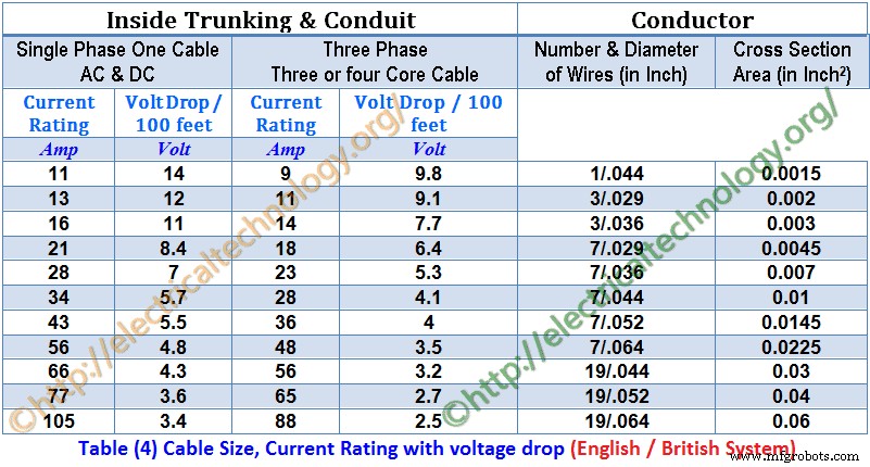
现在从 表 4 中找到这根 (7/0.036) 电缆的 100 英尺电压降 这是 7V , 但在我们的例子中,电缆的长度是 35 英尺。因此,35英尺电缆的电压降为;
35 英尺的实际电压降 =(7 x 35/100) x (24.5/28) =2.1V
而允许压降 =(2.5 x 220)/100 =5.5V
这里实际压降(2.1V)小于最大允许压降5.5V。因此,对于电气布线安装的给定负载,适当且最合适的电缆尺寸为(7/0.036)。
- 相关文章:如何连接自动和手动转换和转换开关? (一期和三期)
示例 2 ... (SI / Metric /十进制)
什么类型和尺寸的电缆适合特定情况
- 负载 =5.8kW
- 伏特 =230V AV
- 电路长度 =35 米
- 温度 =35°C (95°F)
解决办法:-
负载 =5.8kW =5800W
电压 =230V
当前 =I =P/V =5800 / 230 =25.2A
20% 额外负载电流 =(20/100) x 5.2A =5A
总负载电流 =25.2A + 5A =30.2A
现在选择负载电流为 30.2A(来自表 1)的电缆尺寸,即 7/1.04(31 安培)。这意味着我们可以根据 表 1 使用 7/0.036 电缆 .
现在检查选定的 (7/1.04) 电缆与表 3 中的温度系数,因此在 35°C (95°F) 时温度系数为 0.97(在表 3 中) (7/1.04) 的载流能力为 31A,因此该电缆在 40°C (104°F) 时的载流能力为;
35°C (95°F) 时的额定电流 =31 x 0.97 =30 安培。
由于 35°C (95°F) 时的计算值 (30 Amp) 小于 (7/1.04) 电缆的载流能力 31A,因此这种尺寸的电缆(7/1.04)也适合温度。
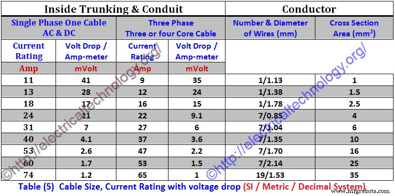
现在从(表 5)中找到这根 (7/1.04) 电缆的每安培米的电压降,即 7mV,但在我们的例子中,电缆的长度是 35仪表。因此,35米电缆的电压降为:
35米实际电压降 =
=mV x I x L
=(7/1000) x 30×35 =7.6V
和允许压降 =(2.5 x 230)/100 =5.75V
这里实际压降(7.35V)大于最大允许压降5.75V。因此,对于给定的负载,这不是合适的电缆尺寸。所以我们将选择下一个所选电缆的尺寸(7/1.04),即7/1.35,并再次找到电压降。
根据表(5),7/1.35的额定电流为40安培,每安培表的电压降为4.1 mV(见表(5))。因此,35米电缆的实际电压降为;
35米实际电压降=
=mV x I x L
(4.1/1000) x 40×35 =7.35V =5.74V
这个压降小于最大允许压降。所以这是最合适和最合适的电缆或电线尺寸 .
示例 3
以下荷载在建筑物中连接:-
子电路1
- 2 个灯,每个 o 1000W 和
- 4个风扇,每个80W
- 2台电视机各120W
子电路2
- 6个灯,每个80W和
- 5个插座,每个100W
- 4 lamps each of 800W
If supply voltages are 230 V AC, then calculate circuit current and Cable size for each Sub-Circuit ?
Solution:-
Total load of Sub-Circuit 1
=(2 x 1000) + (4 x 80) + (2×120)
=2000W + 320W + 240W =2560W
Current for Sub-Circuit 1 =I =P/V =2560/230 =11.1A
Total load of Sub-Circuit 2
=(6 x 80) + (5 x 100) + (4 x 800)
=480W + 500W + 3200W=4180W
Current for Sub-Circuit 2 =I =P/V =4180/230 =18.1A
Therefore, Cable suggested for sub circuit 1 =3/.029 ” (13 Amp ) or 1/1.38 mm (13 Amp )
Cable suggested for Sub-Circuit 2 =7/.029 ” (21 Amp ) or 7/0.85 mm (24 Amp)
Total Current drawn by both Sub-Circuits =11.1A + 18.1A =29.27 A
So cable suggested for Main-Circuit =7/.044″ (34 Amp) or 7/1.04 mm (31 Amp )
Example 4
A 10H.P (7.46kW) three phase squirrel cage induction motor of continuous rating using Star-Delta starting is connected through 400V supply by three single core PVC cables run in conduit from 250feet (76.2m) away from multi-way distribution fuse board. Its full load current is 19A. Average summer temperature in Electrical installation wiring is 35°C (95°F). Calculate the size of the cable for the motor?
Solution:-
- Motor load =10H.P =10 x 746 =7460W *(1H.P =746W)
- Supply Voltage =400V (3-Phase)
- Length of cable =250feet (76.2m)
- Motor full load Current =19A
- Temperature factor for 35°C (95°F) =0.97 (From Table 3)
Now select the size of cable for full load motor current of 19A (from Table 4) which is 7/0.36” (23 Amperes) *(Remember that this is a 3-phase system i.e. 3-core cable) and the voltage drop is 5.3V for 100 Feet. It means we can use 7/0.036 cable according Table (4).
Now check the selected (7/0.036) cable with temperature factor in table (3), so the temperature factor is 0.97 (in table 3) at 35°C (95°F) and current carrying capacity of (7/0.036”) is 23 Amperes, therefore, current carrying capacity of this cable at 40°C (104°F) would be:
Current rating for 40°C (104°F) =23 x 0.97 =22.31 Amp.
Since the calculated value (22.31 Amp) at 35°C (95°F) is less than that of current carrying capacity of (7/0.036) cable which is 23A, therefore this size of cable (7/0.036) is also suitable with respect to temperature.
Load factor =19/23 =0.826
Now find the voltage drop for 100feet for this (7/0.036) cable from table (4) which is 5.3V, But in our case, the length of cable is 250 feet. Therefore, the voltage drop for 250 feet cable would be;
Actual Voltage drop for 250feet =(5.3 x 250/100) x 0.826 =10.94V
And maximum Allowable voltage drop =(2.5/100) x 400V=10V
Here the actual Voltage drop (10.94V) is greater than that of maximum allowable voltage drop of 10V. Therefore, this is a not a suitable size of cable for the given load. So we will select the next size of selected cable (7/0.036) which is 7/0.044 and find the voltage drop again. According to Table (4) the current rating of 7/0.044 is 28 Amperes and the volt drop in per 100 feet is 4.1V (see Table 4). Therefore, the actual voltage drop for 250 feet cable would be;
Actual Voltage drop for 250 feet =
=Volt drop per 100 feet x length of cable x load factor
=(4.1/100) x 250 x 0.826 =8.46V
And Maximum Allowable voltage drop =(2.5/100) x 400V=10V
The actual voltage drop is less than that of maximum allowable voltage drop. So this is the most appropriate and suitable cable size for electrical wiring installation in a given situation.
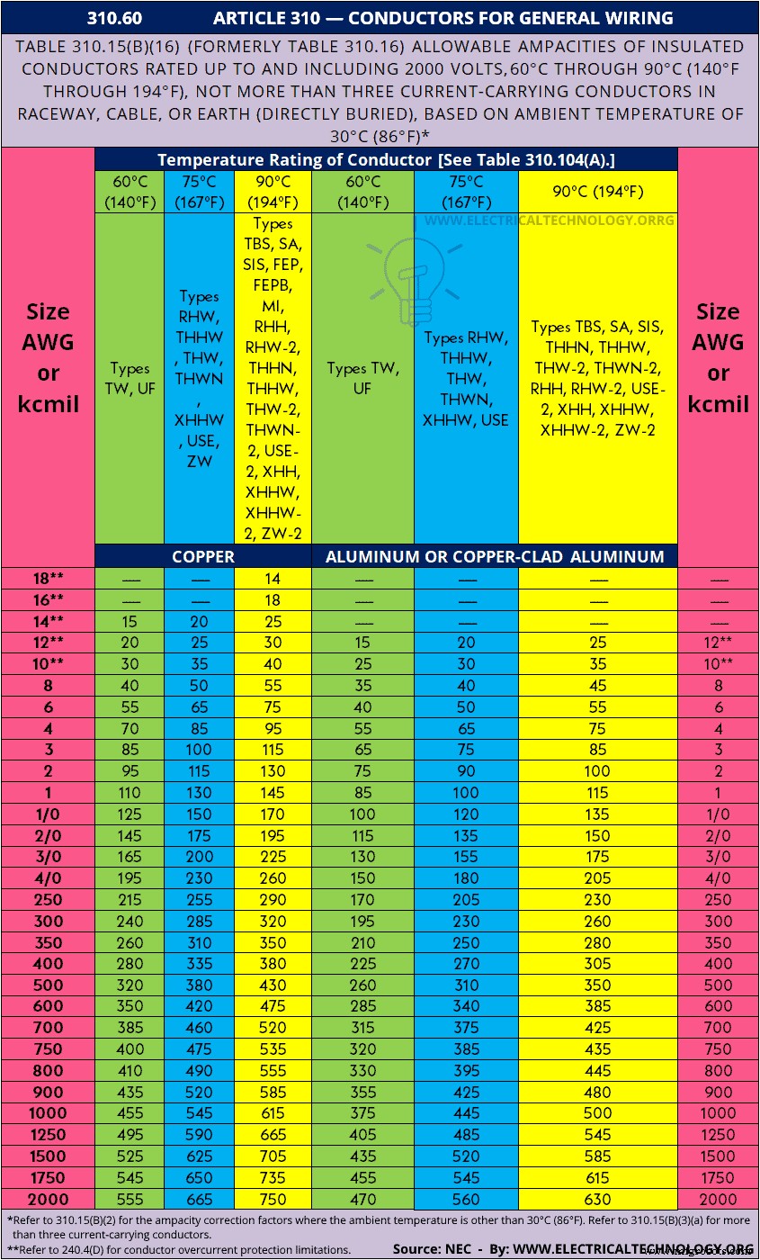
NEC Wire Size Table 310.15(B)(16) (formerly Table 310.16) &Chart
NEC (National Electrical Code) Table 310.15(B)(16) (formerly Table 310.16) – 310.60 – ARTICLE 310 – Conductors for General Wiring &Allowable Ampacities of Conductors &Wire Sizes based on AWG (American Wire Gauge).
| 310.60 ARTICLE 310 — CONDUCTORS FOR GENERAL WIRING | |||||||
| Table 310.15(B)(16) (formerly Table 310.16) Allowable Ampacities of Insulated Conductors Rated Up to and Including 2000 Volts, 60°C Through 90°C (140°F Through 194°F), Not More Than Three Current-Carrying Conductors in Raceway, Cable, or Earth (Directly Buried), Based on Ambient Temperature of 30°C (86°F)* | |||||||
| Size AWG or kcmil | Temperature Rating of Conductor [See Table 310.104(A).] | Size AWG or kcmil | |||||
| 60°C (140°F) | 75°C (167°F) | 90°C (194°F) | 60°C (140°F) | 75°C (167°F) | 90°C (194°F) | ||
| Types TW, UF | Types RHW, THHW, THW, THWN, XHHW, USE, ZW | Types TBS, SA, SIS, FEP, FEPB, MI, RHH, RHW-2, THHN, THHW, THW-2, THWN-2, USE-2, XHH, XHHW, XHHW-2, ZW-2 | Types TW, UF | Types RHW, THHW, THW, THWN, XHHW, USE | Types TBS, SA, SIS, THHN, THHW, THW-2, THWN-2, RHH, RHW-2, USE-2, XHH, XHHW, XHHW-2, ZW-2 | ||
| COPPER | ALUMINUM OR COPPER-CLAD ALUMINUM | ||||||
| 18** | — | — | 14 | — | — | — | — |
| 16** | — | — | 18 | — | — | — | — |
| 14** | 15 | 20 | 25 | — | — | — | — |
| 12** | 20 | 25 | 30 | 15 | 20 | 25 | 12** |
| 10** | 30 | 35 | 40 | 25 | 30 | 35 | 10** |
| 8 | 40 | 50 | 55 | 35 | 40 | 45 | 8 |
| 6 | 55 | 65 | 75 | 40 | 50 | 55 | 6 |
| 4 | 70 | 85 | 95 | 55 | 65 | 75 | 4 |
| 3 | 85 | 100 | 115 | 65 | 75 | 85 | 3 |
| 2 | 95 | 115 | 130 | 75 | 90 | 100 | 2 |
| 1 | 110 | 130 | 145 | 85 | 100 | 115 | 1 |
| 1/0 | 125 | 150 | 170 | 100 | 120 | 135 | 1/0 |
| 2/0 | 145 | 175 | 195 | 115 | 135 | 150 | 2/0 |
| 3/0 | 165 | 200 | 225 | 130 | 155 | 175 | 3/0 |
| 4/0 | 195 | 230 | 260 | 150 | 180 | 205 | 4/0 |
| 250 | 215 | 255 | 290 | 170 | 205 | 230 | 250 |
| 300 | 240 | 285 | 320 | 195 | 230 | 260 | 300 |
| 350 | 260 | 310 | 350 | 210 | 250 | 280 | 350 |
| 400 | 280 | 335 | 380 | 225 | 270 | 305 | 400 |
| 500 | 320 | 380 | 430 | 260 | 310 | 350 | 500 |
| 600 | 350 | 420 | 475 | 285 | 340 | 385 | 600 |
| 700 | 385 | 460 | 520 | 315 | 375 | 425 | 700 |
| 750 | 400 | 475 | 535 | 320 | 385 | 435 | 750 |
| 800 | 410 | 490 | 555 | 330 | 395 | 445 | 800 |
| 900 | 435 | 520 | 585 | 355 | 425 | 480 | 900 |
| 1000 | 455 | 545 | 615 | 375 | 445 | 500 | 1000 |
| 1250 | 495 | 590 | 665 | 405 | 485 | 545 | 1250 |
| 1500 | 525 | 625 | 705 | 435 | 520 | 585 | 1500 |
| 1750 | 545 | 650 | 735 | 455 | 545 | 615 | 1750 |
| 2000 | 555 | 665 | 750 | 470 | 560 | 630 | 2000 |
| |||||||
Here is the NEC table as a chart (image format to downloads as a reference)
Related Posts:
- How to Size a Load Center, Panelboards and Distribution Board?
- How to Determine the Number of Circuit Breakers in a Panel Board?
- How to Determine the Right Size Capacity of a Subpanel?
- How to Calculate the Suitable Capacitor Size in Farads &kVAR for Power factor Improvement
- How to Convert Capacitor Farads into kVAR &Vice Versa (For Power factor improvement)
- How To check a Capacitor with Digital &Analog Multimeter. 8 Methods
- How to Check the Value of Burnt Resistor. 3 Handy methods
- How To:Electrical &Electronics Tutorials
- Basic Electrical Wiring Installation Tutorials
工业技术