

组合逻辑与永远
verilog always 块可用于顺序逻辑和组合逻辑。使用 assign 显示了一些设计示例 上一篇文章中的说法。接下来将使用 always 探索同一组设计 块。
示例 #1:简单的组合逻辑
下面显示的代码实现了一个简单的数字组合逻辑,它有一个名为 z 的输出信号,类型为 reg 每当敏感度列表中的信号之一更改其值时,它就会更新。敏感度列表在 @ 之后的括号内声明 运营商。
module combo ( 	input 	a, b, c, d, e,
								output 	reg z);

	always @ ( a or b or c or d or e) begin
		z = ((a & b) | (c ^ d) & ~e);
	end

endmodule
模块 combo 使用综合工具将其细化成如下硬件原理图,可以看出组合逻辑是用数字门实现的。
<无脚本>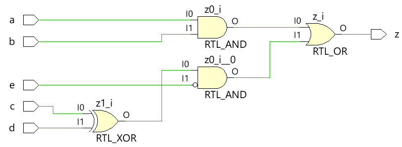
<无脚本>  使用 always 块对组合逻辑进行建模时使用阻塞分配
测试台
测试台是一个用于模拟设计的平台,以确保设计的行为符合预期。所有输入组合都使用 for 驱动到设计模块 使用 10 个时间单位的延迟语句循环,以便在一段时间后将新值应用于输入。
module tb;
	// Declare testbench variables
  reg a, b, c, d, e;
  wire z;
  integer i;

  // Instantiate the design and connect design inputs/outputs with
  // testbench variables
  combo u0 ( .a(a), .b(b), .c(c), .d(d), .e(e), .z(z));

  initial begin
  	// At the beginning of time, initialize all inputs of the design
  	// to a known value, in this case we have chosen it to be 0.
    a <= 0;
    b <= 0;
    c <= 0;
    d <= 0;
    e <= 0;

    // Use a $monitor task to print any change in the signal to
    // simulation console
    $monitor ("a=%0b b=%0b c=%0b d=%0b e=%0b z=%0b",
              a, b, c, d, e, z);

    // Because there are 5 inputs, there can be 32 different input combinations
    // So use an iterator "i" to increment from 0 to 32 and assign the value
    // to testbench variables so that it drives the design inputs
    for (i = 0; i < 32; i = i + 1) begin
      {a, b, c, d, e} = i;
      #10;
    end
  end
endmodule
模拟日志ncsim> run a=0 b=0 c=0 d=0 e=0 z=0 a=0 b=0 c=0 d=0 e=1 z=0 a=0 b=0 c=0 d=1 e=0 z=1 a=0 b=0 c=0 d=1 e=1 z=0 a=0 b=0 c=1 d=0 e=0 z=1 a=0 b=0 c=1 d=0 e=1 z=0 a=0 b=0 c=1 d=1 e=0 z=0 a=0 b=0 c=1 d=1 e=1 z=0 a=0 b=1 c=0 d=0 e=0 z=0 a=0 b=1 c=0 d=0 e=1 z=0 a=0 b=1 c=0 d=1 e=0 z=1 a=0 b=1 c=0 d=1 e=1 z=0 a=0 b=1 c=1 d=0 e=0 z=1 a=0 b=1 c=1 d=0 e=1 z=0 a=0 b=1 c=1 d=1 e=0 z=0 a=0 b=1 c=1 d=1 e=1 z=0 a=1 b=0 c=0 d=0 e=0 z=0 a=1 b=0 c=0 d=0 e=1 z=0 a=1 b=0 c=0 d=1 e=0 z=1 a=1 b=0 c=0 d=1 e=1 z=0 a=1 b=0 c=1 d=0 e=0 z=1 a=1 b=0 c=1 d=0 e=1 z=0 a=1 b=0 c=1 d=1 e=0 z=0 a=1 b=0 c=1 d=1 e=1 z=0 a=1 b=1 c=0 d=0 e=0 z=1 a=1 b=1 c=0 d=0 e=1 z=1 a=1 b=1 c=0 d=1 e=0 z=1 a=1 b=1 c=0 d=1 e=1 z=1 a=1 b=1 c=1 d=0 e=0 z=1 a=1 b=1 c=1 d=0 e=1 z=1 a=1 b=1 c=1 d=1 e=0 z=1 a=1 b=1 c=1 d=1 e=1 z=1 ncsim: *W,RNQUIE: Simulation is complete.<无脚本>
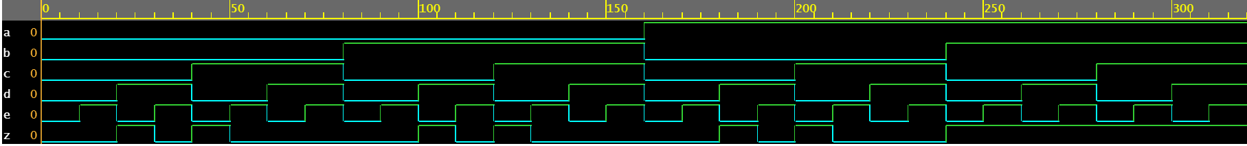
请注意,这两种方法 assign 和 always ,实现到相同的硬件逻辑中。
示例 #2:半加器
半加器模块接受两个标量输入 a 和 b,并使用组合逻辑来分配输出信号 sum 和进位 cout。和由 a 和 b 之间的 XOR 驱动,而进位位由两个输入之间的 AND 获得。
module ha ( input 	a, b,
						output	sum, cout);

	always @ (a or b) begin
		{cout, sum} = a + b;
	end

endmodule
<无脚本> 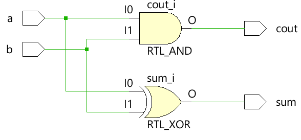
测试台
module tb;
	// Declare testbench variables
  reg a, b;
  wire sum, cout;
  integer i;

  // Instantiate the design and connect design inputs/outputs with
  // testbench variables
  ha u0 ( .a(a), .b(b), .sum(sum), .cout(cout));

  initial begin
  	// At the beginning of time, initialize all inputs of the design
  	// to a known value, in this case we have chosen it to be 0.
    a <= 0;
    b <= 0;

    // Use a $monitor task to print any change in the signal to
    // simulation console
    $monitor("a=%0b b=%0b sum=%0b cout=%0b", a, b, sum, cout);

    // Because there are only 2 inputs, there can be 4 different input combinations
    // So use an iterator "i" to increment from 0 to 4 and assign the value
    // to testbench variables so that it drives the design inputs
    for (i = 0; i < 4; i = i + 1) begin
      {a, b} = i;
      #10;
    end
  end
endmodule
模拟日志ncsim> run a=0 b=0 sum=0 cout=0 a=0 b=1 sum=1 cout=0 a=1 b=0 sum=1 cout=0 a=1 b=1 sum=0 cout=1 ncsim: *W,RNQUIE: Simulation is complete.<无脚本>

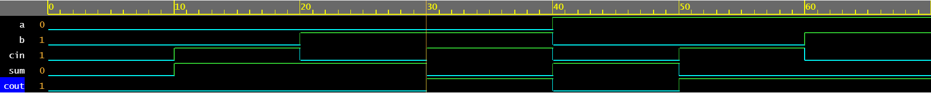
示例 #3:全加器
always 块可用于描述全加器的行为,以驱动输出 sum 和 cout。
module fa (	input 	a, b, cin,
			output reg	sum, cout);

  always @ (a or b or cin) begin
    {cout, sum} = a + b + cin;
  end

endmodule
<无脚本> 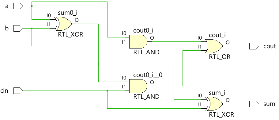
测试台
module tb;
  reg a, b, cin;
  wire sum, cout;
  integer i;

  fa u0 ( .a(a), .b(b), .cin(cin), .sum(sum), .cout(cout));

  initial begin
    a <= 0;
    b <= 0;

    $monitor("a=%0b b=%0b cin=%0b cout=%0b sum=%0b", a, b, cin, cout, sum);

    for (i = 0; i < 8; i = i + 1) begin
      {a, b, cin} = i;
      #10;
    end
  end
endmodule
模拟日志ncsim> run a=0 b=0 cin=0 cout=0 sum=0 a=0 b=0 cin=1 cout=0 sum=1 a=0 b=1 cin=0 cout=0 sum=1 a=0 b=1 cin=1 cout=1 sum=0 a=1 b=0 cin=0 cout=0 sum=1 a=1 b=0 cin=1 cout=1 sum=0 a=1 b=1 cin=0 cout=1 sum=0 a=1 b=1 cin=1 cout=1 sum=1 ncsim: *W,RNQUIE: Simulation is complete.<无脚本>
示例 #4:2x1 多路复用器
简单的 2x1 多路复用器使用三元运算符来决定应将哪个输入分配给输出 c。如果sel为1,则输出由a驱动,如果sel为0,则输出由b驱动。
module mux_2x1 (input 	a, b, sel,
				output 	reg c);


  always @ ( a or b or sel) begin
	c = sel ? a : b;
  end
endmodule
<无脚本> 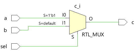
测试台
module tb;
	// Declare testbench variables
  reg a, b, sel;
  wire c;
  integer i;

  // Instantiate the design and connect design inputs/outputs with
  // testbench variables
  mux_2x1 u0 ( .a(a), .b(b), .sel(sel), .c(c));

  initial begin
  	// At the beginning of time, initialize all inputs of the design
  	// to a known value, in this case we have chosen it to be 0.
    a <= 0;
    b <= 0;
    sel <= 0;

    $monitor("a=%0b b=%0b sel=%0b c=%0b", a, b, sel, c);

    for (i = 0; i < 3; i = i + 1) begin
      {a, b, sel} = i;
      #10;
    end
  end
endmodule
模拟日志ncsim> run a=0 b=0 sel=0 c=0 a=0 b=0 sel=1 c=0 a=0 b=1 sel=0 c=1 ncsim: *W,RNQUIE: Simulation is complete.<无脚本>

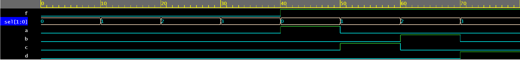
示例 #5:1x4 解复用器
解复用器使用 sel 和 f 输入的组合来驱动不同的输出信号。每个输出信号的类型为 reg 并在 always 中使用 根据敏感度列表中列出的信号的变化而更新的块。
module demux_1x4 (	input 				f,
										input [1:0]	 	sel,
										output reg		a, b, c, d);

  always @ ( f or sel) begin
    a = f & ~sel[1] & ~sel[0];
    b = f &  sel[1] & ~sel[0];
    c = f & ~sel[1] &  sel[0];
    d = f &  sel[1] &  sel[0];
  end

endmodule
<无脚本> 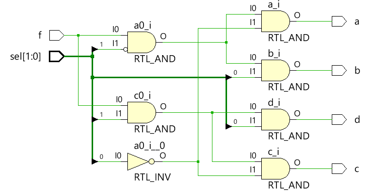
测试台
module tb;
	// Declare testbench variables
  reg f;
  reg [1:0] sel;
  wire a, b, c, d;
  integer i;

  // Instantiate the design and connect design inputs/outputs with
  // testbench variables
  demux_1x4 u0 ( .f(f), .sel(sel), .a(a), .b(b), .c(c), .d(d));

  // At the beginning of time, initialize all inputs of the design
  // to a known value, in this case we have chosen it to be 0.
  initial begin
    f <= 0;
    sel <= 0;

    $monitor("f=%0b sel=%0b a=%0b b=%0b c=%0b d=%0b", f, sel, a, b, c, d);

    // Because there are 3 inputs, there can be 8 different input combinations
    // So use an iterator "i" to increment from 0 to 8 and assign the value
    // to testbench variables so that it drives the design inputs
    for (i = 0; i < 8; i = i + 1) begin
      {f, sel} = i;
      #10;
    end
  end
endmodule
模拟日志ncsim> run f=0 sel=0 a=0 b=0 c=0 d=0 f=0 sel=1 a=0 b=0 c=0 d=0 f=0 sel=10 a=0 b=0 c=0 d=0 f=0 sel=11 a=0 b=0 c=0 d=0 f=1 sel=0 a=1 b=0 c=0 d=0 f=1 sel=1 a=0 b=0 c=1 d=0 f=1 sel=10 a=0 b=1 c=0 d=0 f=1 sel=11 a=0 b=0 c=0 d=1 ncsim: *W,RNQUIE: Simulation is complete.<无脚本>
示例 #6:4x16 解码器
module dec_3x8 ( 	input 			en,
					input 	[3:0] 	in,
					output  reg [15:0] 	out);

  always @ (en or in) begin
    out = en ? 1 << in: 0;
  end

endmodule
<无脚本> 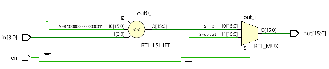
测试台
module tb;
  reg en;
  reg [3:0] in;
  wire [15:0] out;
  integer i;

  dec_3x8 u0 ( .en(en), .in(in), .out(out));

  initial begin
    en <= 0;
    in <= 0;

    $monitor("en=%0b in=0x%0h out=0x%0h", en, in, out);

    for (i = 0; i < 32; i = i + 1) begin
      {en, in} = i;
      #10;
    end
  end
endmodule
模拟日志ncsim> run en=0 in=0x0 out=0x0 en=0 in=0x1 out=0x0 en=0 in=0x2 out=0x0 en=0 in=0x3 out=0x0 en=0 in=0x4 out=0x0 en=0 in=0x5 out=0x0 en=0 in=0x6 out=0x0 en=0 in=0x7 out=0x0 en=0 in=0x8 out=0x0 en=0 in=0x9 out=0x0 en=0 in=0xa out=0x0 en=0 in=0xb out=0x0 en=0 in=0xc out=0x0 en=0 in=0xd out=0x0 en=0 in=0xe out=0x0 en=0 in=0xf out=0x0 en=1 in=0x0 out=0x1 en=1 in=0x1 out=0x2 en=1 in=0x2 out=0x4 en=1 in=0x3 out=0x8 en=1 in=0x4 out=0x10 en=1 in=0x5 out=0x20 en=1 in=0x6 out=0x40 en=1 in=0x7 out=0x80 en=1 in=0x8 out=0x100 en=1 in=0x9 out=0x200 en=1 in=0xa out=0x400 en=1 in=0xb out=0x800 en=1 in=0xc out=0x1000 en=1 in=0xd out=0x2000 en=1 in=0xe out=0x4000 en=1 in=0xf out=0x8000 ncsim: *W,RNQUIE: Simulation is complete.<无脚本>

Verilog