

车载 GPS 追踪器与 thinger.io 地图集成
组件和用品
 |
| × | 1 | |||
| × | 1 | ||||
| × | 1 | ||||
 |
| × | 1 | |||
 |
| × | 2 | |||
 |
| × | 2 | |||
| × | 1 | ||||
| × | 1 | ||||
| × | 1 | ||||
 |
| × | 1 |
必要的工具和机器
| |
|
应用和在线服务
 |
|
关于这个项目
这个项目最初是一个简单的“GPS 追踪器创意”,后来变成了“多用途 GPS 追踪器”。作为我的第一个项目,学习曲线很陡峭,因此我总是对设计的输入、反馈和改进持开放态度! :)
该追踪器旨在放置在我的汽车中,并具有以下功能:
- 每 2 分钟跟踪 GPS 坐标并将最后已知位置发布到 thinger.io IoT 云仪表板(显示在地图上)。使用 HTTP POST 请求发布到 thinger.io。
- 回复 SMS 命令并返回指向当前或最后已知位置的 Google 地图链接(如果当前位置不可用,则返回最后已知位置)。
- 每 XX 公里发送一条短信通知(这个想法是让跟踪器提醒我每 4000 公里清空我的油箱)。这可用作可自定义的软件“里程表”。
在这个项目中,我很快意识到 Arduino 在可用内存方面是多么“有限”,我必须学习减少开销和编写高效代码的技术(至少我已经尝试过)。我还使用了轻量级库来适应芯片上的所有内容和可用的 RAM。
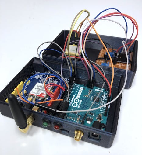
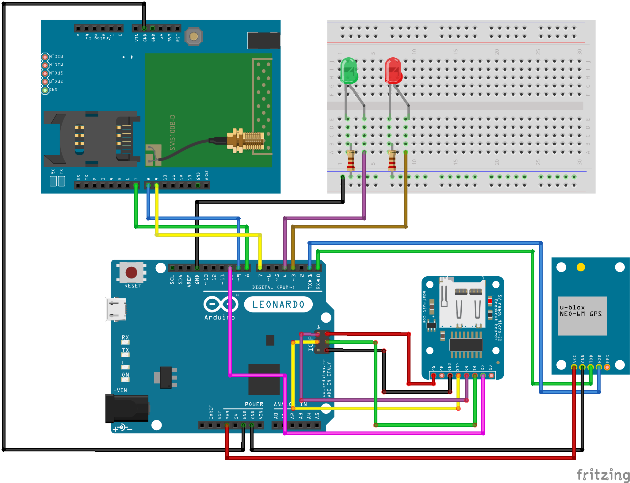
使用的组件如下(如组件列表中所示):
- NEO-6M GPS 设备。这似乎是一种非常流行的 GPS 设备,可在 Ebay 和类似产品中便宜地买到。与 GPS 的通信将是硬件串行。
- GPS 天线。任何兼容的都可以,但是,我发现 Ebay 最便宜的产品效果不佳,即接收不良/卫星数量少。也许我只是用第一根天线不走运,但为了稳定接收,我不得不再买一根质量更好的天线。
- 用于 GSM 和 GPRS 连接的 SIM900 开发板。该项目也应与 SIM800 和兼容模块一起使用,但不能保证。与 SIM900 的通信将是软件串行。
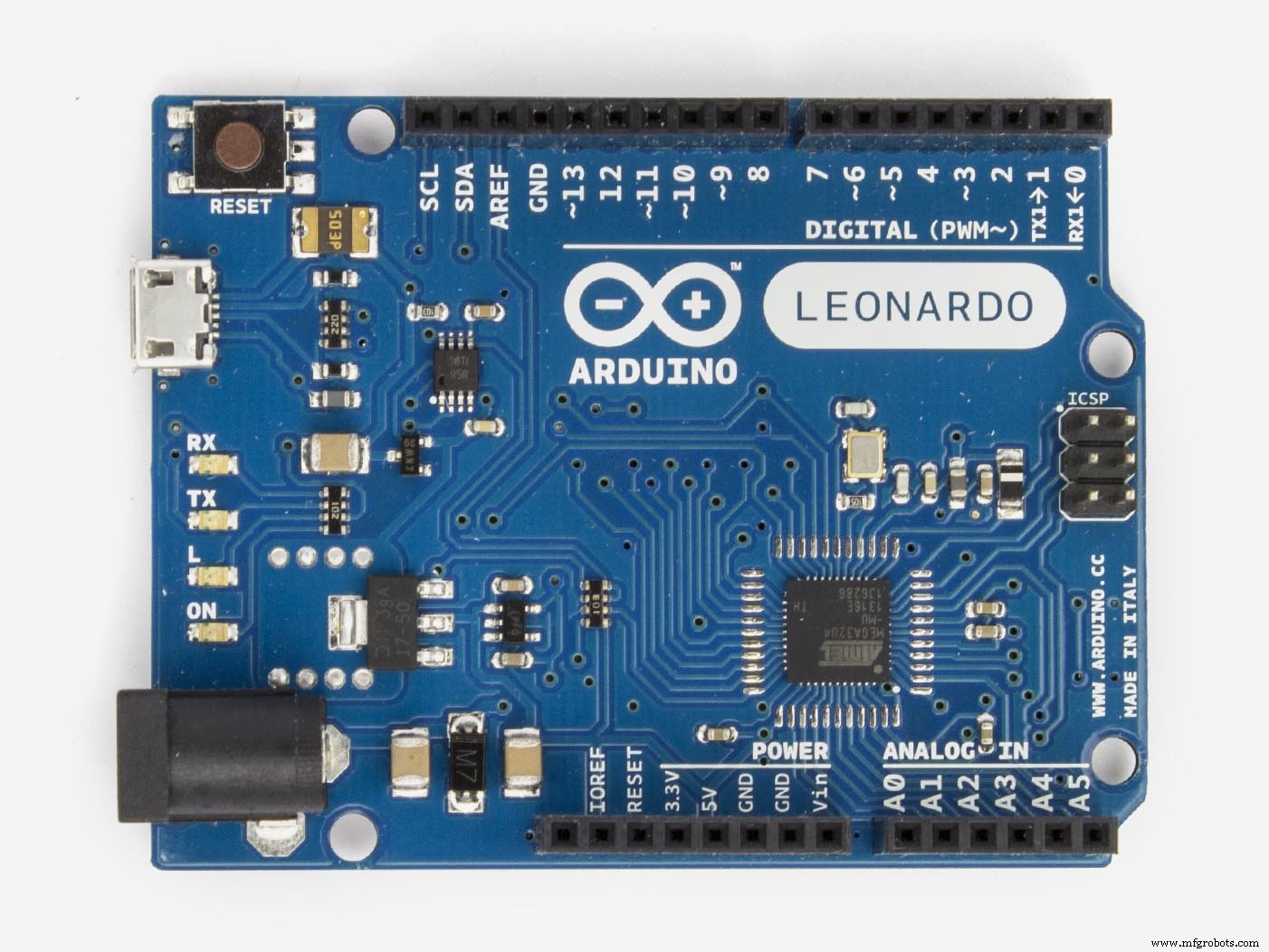
- Arduino莱昂纳多 木板。我使用 Leonardo 板有一个专用硬件串行线, 因为我们需要两条串行线。虽然也可以使用普通的 UNO 板,但您必须断开 GPS 才能下载软件,而且您也没有用于调试的串行监视器。我们需要两根串口线(一根用于GPS,一根用于SIM900板);一个软件序列号和一个硬件序列号。
- SD 读卡器(我使用了兼容 5V 的 Adafruit 读卡器(可以轻松连接到 5V SPI 接头)。其他更便宜的模块可能也能正常工作。微型 SD 卡将用于存储行进的距离。警告: 如果按照我的原理图,请确保您的 SD 卡读卡器支持 5V 电源,许多 SD 卡读卡器仅使用 3.3V。使用不正确的电压电平很可能会损坏电子设备。与 SD 卡读卡器的通信将采用 SPI 接口。
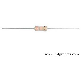
- 用于制作状态指示电路的 LED 和电阻器(电源和 GPS 锁定 LED)。
- 带有数据的 SIM 卡。
- 我还设计了一个带有附加 STL 文件的 3D 可打印外壳,可以直接在 3D 打印机上打印。
首先,我们需要安装必要的库。我为这个项目使用了以下库:
- NeoGPS 用于 GPS 跟踪和解码。可以直接从 Arduino IDE 中的库管理器安装。更多信息:https://github.com/SlashDevin/NeoGPS
- 时间 库(用于 UTC 时区转换):https://github.com/PaulStoffregen/Time
- PetitFS 用于读/写 SD 卡:https://github.com/greiman/PetitFS 轻量级 SD FAT 库。
为什么不使用 Arduino 的可用库 thinger.io?
尽管 thinger.io 提供的库非常易于使用并且可以显着简化事情,更不用说已经集成到 IDE 中了,但它消耗了 Arduino Leo 上近 80% 的存储空间,几乎没有空间用于剩余代码。所以对于这个项目来说它太大了,我们将不得不以艰难的方式去做。为了与 thinger.io 云通信,我们将使用 HTTP POST 请求。
短信 命令
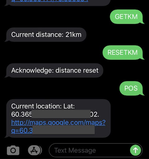
SMS 上可用的命令如下(全部大写)。这些是提供的代码中支持的命令;您可以为自己的项目/需求添加/删除命令:
- “POS” 如果坐标可用,则返回带有 Google 地图链接的坐标。否则,返回最后一个已知位置。
- “GETKM” 返回自上次“重置”以来的当前距离。
- “RESETKM” 将距离计数器设置为 0(重置里程表)。
 &hfig=compress%280/201_a_8ErEiJY7JI.jpeg?auto=compress%610/>&hfig=max50/2010-2010>
设置 NeoGPS
我们使用 NeoGPS 库来实现性能和资源使用,而不是像 TinyGPS++ 这样的替代品。它消耗很少的 RAM,这是必需的;否则我们会收到内存不足和稳定性不足的警告。
库安装完成后,修改GPSPort.h文件 在库安装路径中(给出的示例适用于 OS X - 对于 Windows,您将在不同的位置找到库)
将 GPSPort.h 中的所有内容替换为以下内容:
#ifndef GPSport_h#define GPSport_h#define gpsPort Serial1#define GPS_PORT_NAME "Serial1"#define DEBUG_PORT Serial#endif 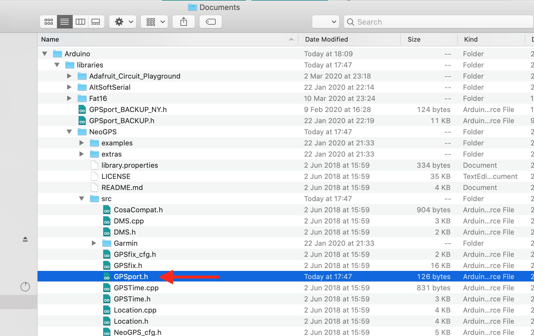
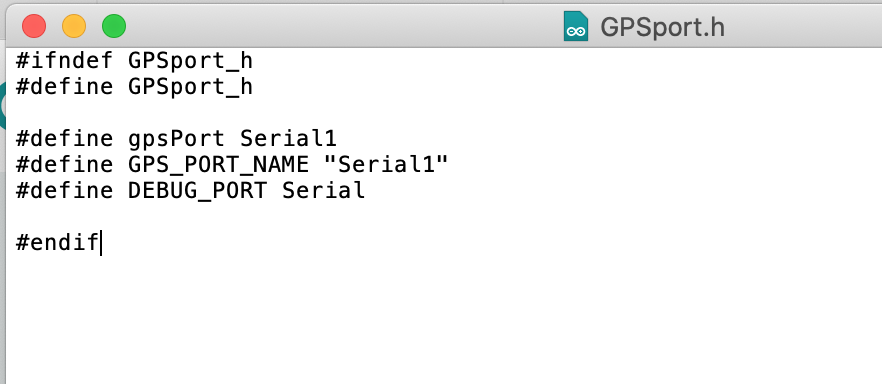
该文件包含 NeoGPS 库使用的定义。如果您使用不同的 Arduino 板,您可以在此处定义 GPS 接收器的串行线路,例如Arduino MEGA 的“Serial2”、“Serial3”。
关于准确性的说明
需要注意的是,GPS 并不是最准确的测量和累积距离的方法,因为即使在静止状态下,位置也会有轻微的漂移。您可以通过站在同一地点进行测试,并观察每次读数的 GPS 坐标都会不同。对于这种应用,准确性不太重要,因此较小的偏差是可以的。
然而,我试图考虑坐标中的小漂移,并且软件仅增加超过 10m 的移动距离(所有低于 10m 的移动都假定为静止)超过 15 秒。
还要记住,距离是按直线计算的,而汽车行驶的实际距离取决于道路、弯道等。我将采样率设置为 15 秒,但是如果您想要更高,可以降低该值准确性。
设置 PetitFS
这个库是一个超轻量级的库,用于读/写 FAT 格式的 SD 卡。我花了一些时间来弄清楚这是如何工作的,因为文档几乎不存在,有些地方甚至是错误的/过时的。提供的库示例代码甚至无法编译。它带有批 限制(而不是像 Arduino 的 SD 库或 SDFat 这样的“普通”库):
- 无法创建文件。只能写入现有文件。
- 无法扩展文件大小。
- 无法更新文件的时间戳。
- 无法将数据附加到文件(每次都重写文件)。
- 任何时候只打开一个文件。
为什么要使用一个有很多怪癖的小而有限的图书馆?
大小,基本上。我尝试了一些库,包括 Arduino SD 库、SDFat 和 fat16lib。它们太大了,无法让所有代码都适合芯片,所以为了不删除功能,我使用了这个库(标准 Arduino SD 库需要大约 12% 以上的空间)。即使有所有的怪癖和限制,它仍然为这个应用程序提供了我们需要的东西:简单的读取和写入单个存储值。
如果您不使用所有代码并且有足够的空间来挤入一些额外的代码,那么使用标准 SD 库等库会容易得多。

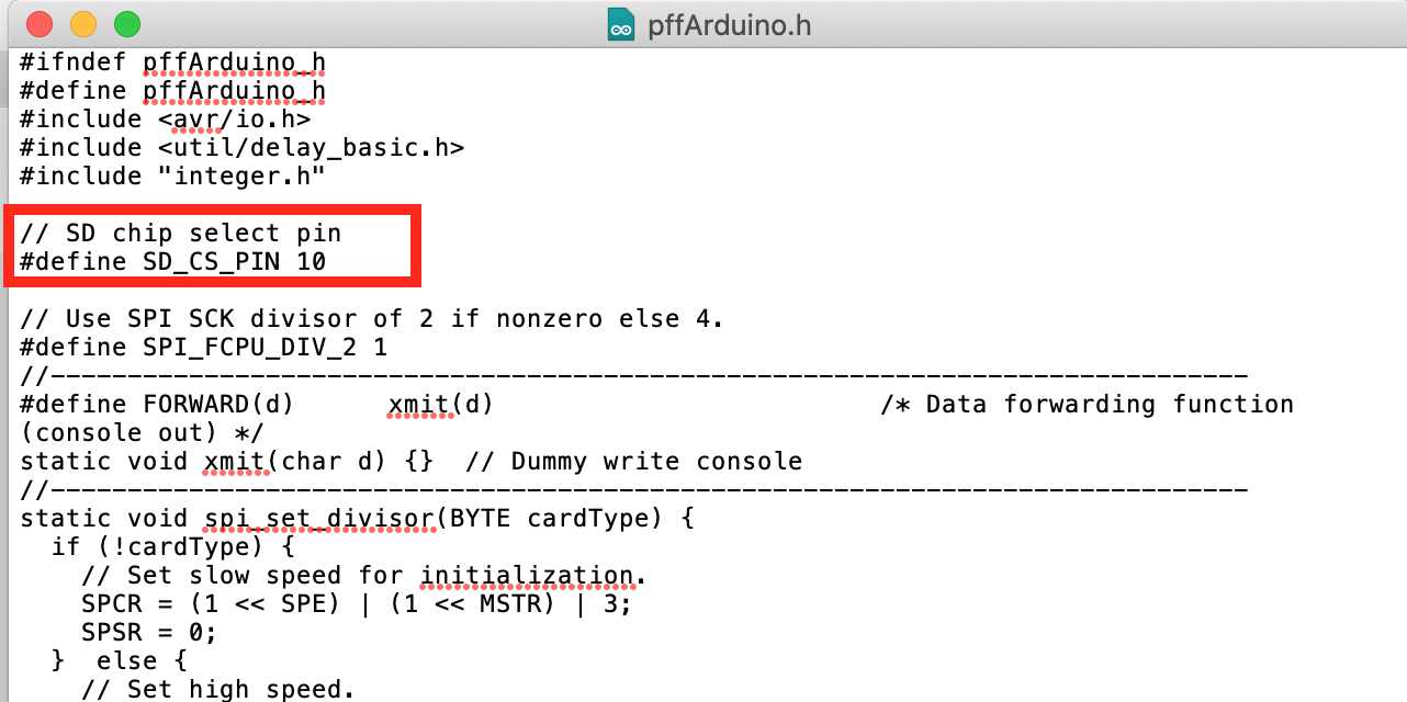
打开文件 pffArduino.h 来自 PetitFS 库文件夹。更改SD_CS_PIN 到 10. 这是用于与带有SPI的SD卡通信的SS引脚。
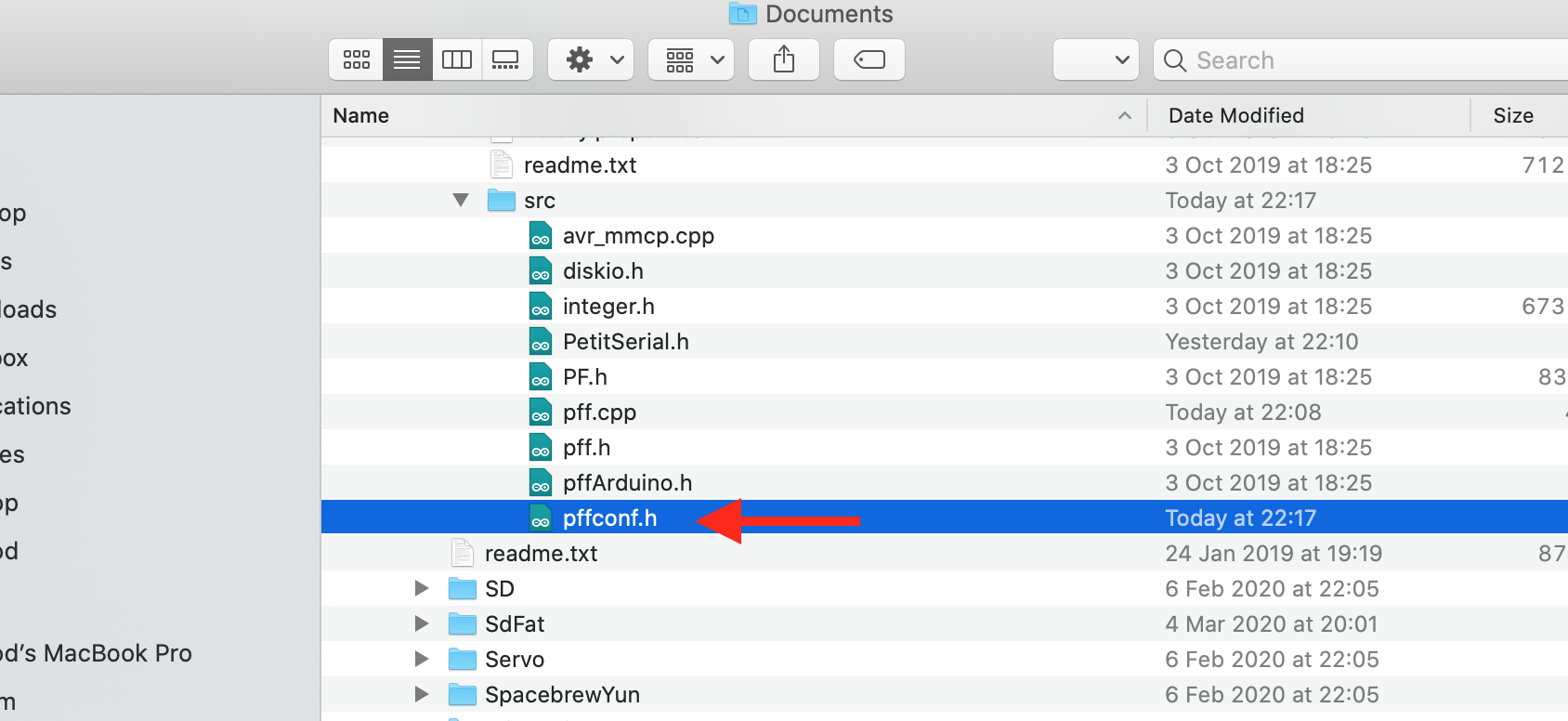
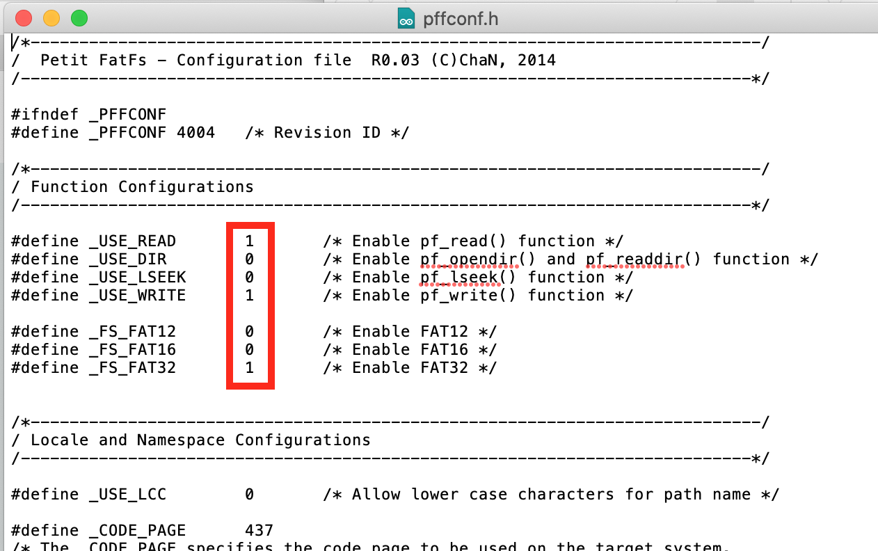
打开文件 pffconf.h 从库文件夹。 禁用 通过将设置值从 1 切换为 0 可以选择以下选项:
- _USE_DIR
- _USE_LSEEK
- _FS_FAT12
- _FS_FAT16
通过禁用这些选项,编译后的程序占用的空间更少——这是必需的;最后的草图大约需要。 96% 的存储空间。
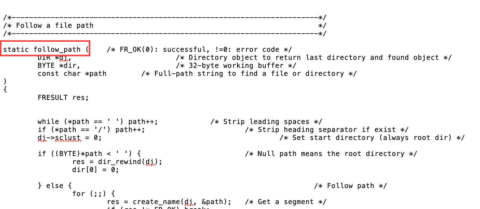
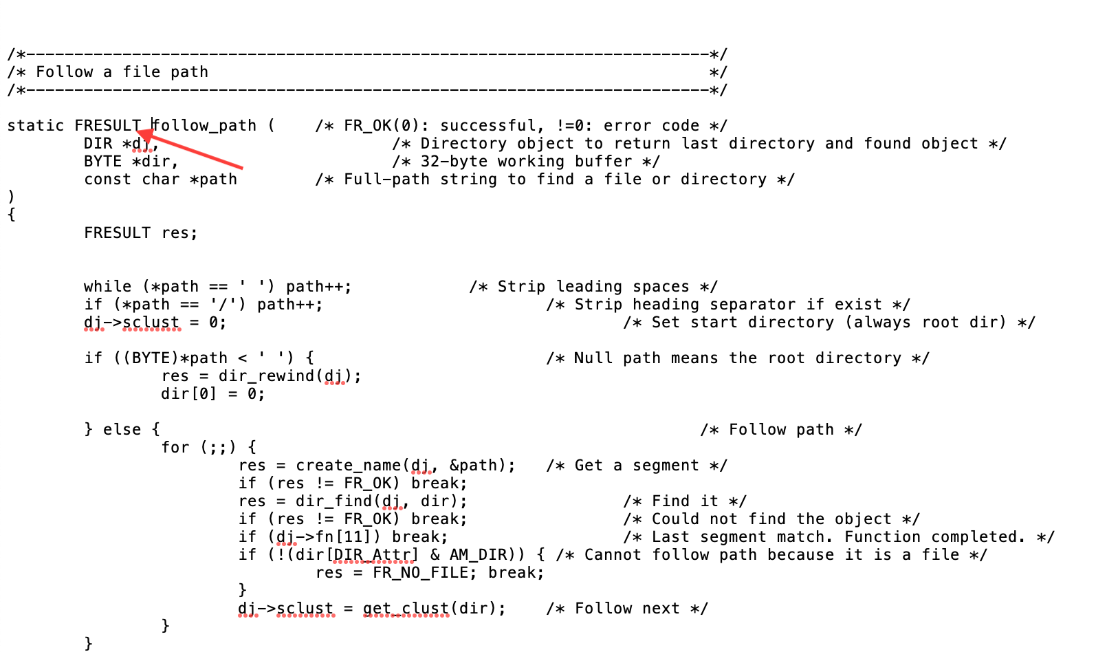
在第一次导入库时,你会得到一个编译错误,*可以* 被忽略(第二次编译错误没有显示 - 仍然不明白为什么)。但是,如果您想修复此问题(每次启动 Arduino IDE -> 编译时它都会重新出现),请添加缺失的函数返回参数“FRESULT”,如上图所示。这是在文件 pff.cpp 中 在库文件夹中。
我已尽力弄清楚这个库是如何工作的,虽然我已经做好了一切工作,但我很确定事情也可以改进。如果您发现我写的套路有错误或改进之处,请随时分享!我非常想学习和积累更多的经验。
准备SD卡
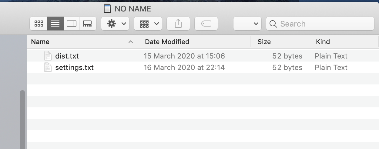
我在这个项目中使用了 Micro SD 卡。由于库本身无法创建文件,因此在使用前在卡上创建文件“dist.txt”和“settings.txt”很重要。我建议复制附加的“dist.txt”和“settings.txt” 来自此项目页面的文件,因为这些文件已经具有正确的格式并且可以正常工作(库非常 对文本格式和内容很挑剔)。
在将文件放入 Micro SD 卡之前,请确保正确格式化卡(如 FAT32 )。我建议使用 SD 协会的官方“SD 卡格式化程序”:https://www.sdcard.org/downloads/formatter/。
确保 SD 卡正常工作(正确读取/写入文件)
PetitFS 库非常 对输入文件很挑剔。如果您启动设备并且串行监视器中没有显示任何输出(只是空白),则很可能卡在“循环”中,它试图从卡读取文件但由于某种原因无法读取(initializeSD() 函数)。我有无数的文本文件由于某种原因无法阅读,因此我包含了我使用过的引用文本文件。 放置这些参考 SD 卡上的文件,它应该能够正确读取和写入。
另一种选择是用更大的数字填充文本文件 比它的写作。我没有测试过这个,但由于库本身不能扩展文件大小,我假设这可能是一个问题。
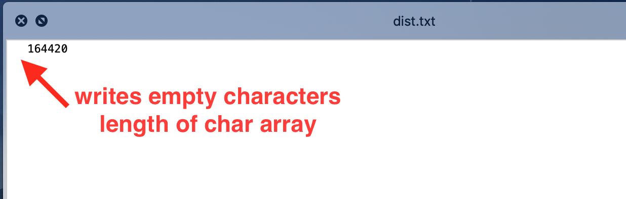
PetitFS 会将字符数组的整个长度写入文件,因此您会在实际数字前面看到空格(除非数字大到足以填满数组——“数组”长度在代码中定义)。更改文件时必须保留这些空格 - 由于 PetitFS 无法更改文件大小,如果更改字符数可能会导致问题。
如果您希望里程表从“0”或任何其他数字开始,请将“dist.txt”文件设置为“0”,以便轻松验证它是否有效,例如发送“GETKM”命令验证短信回复。
在“settings.txt”中设置通知触发距离,里程表触发通知短信的距离(以米为单位)。
准备SIM900板
在我们使用之前,必须在 SIM900 板上设置一些东西。有关详细信息,请访问 https://lastminuteengineers.com/sim900-gsm-shield-arduino-tutorial/ 提供有关此板设置的大量资源。
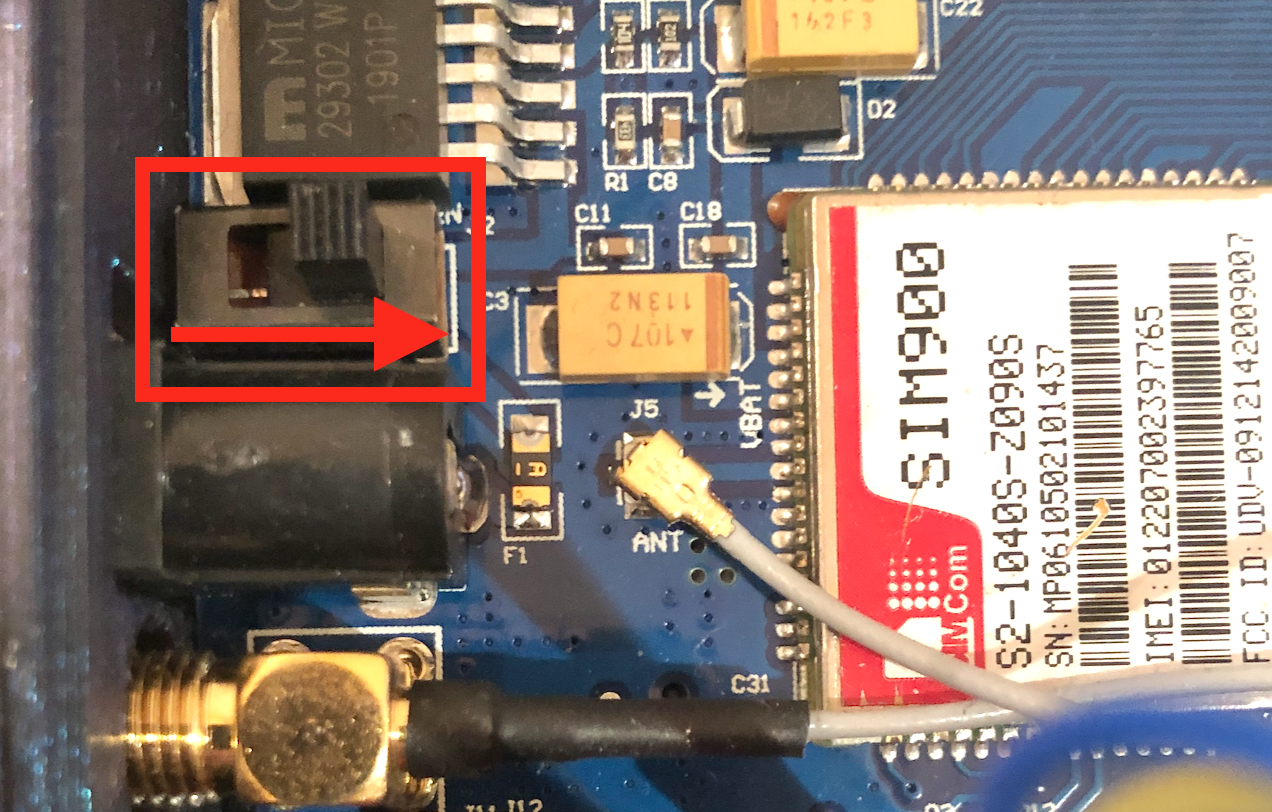
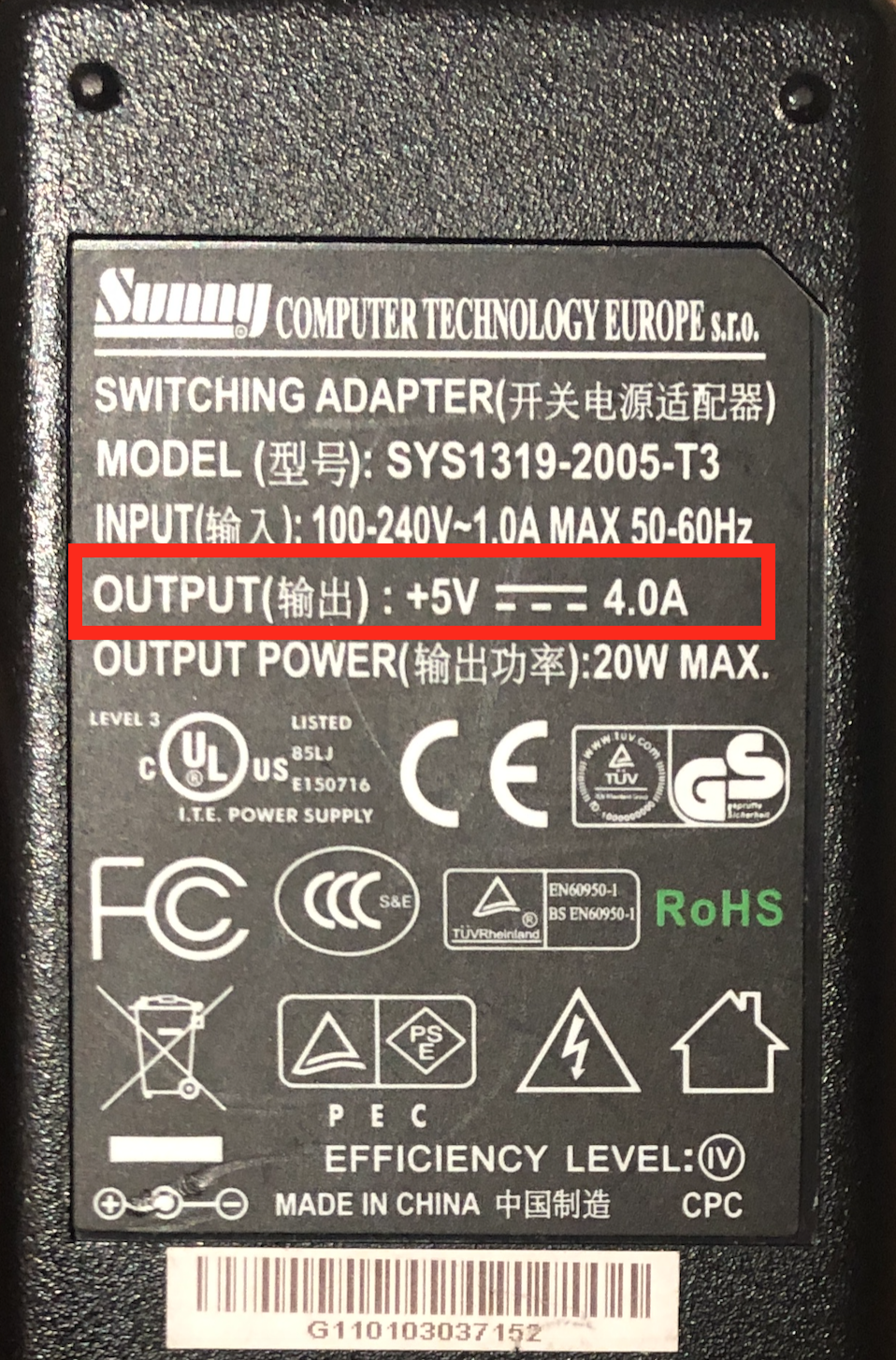
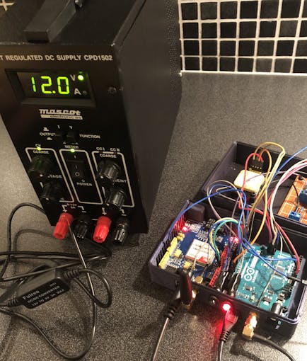
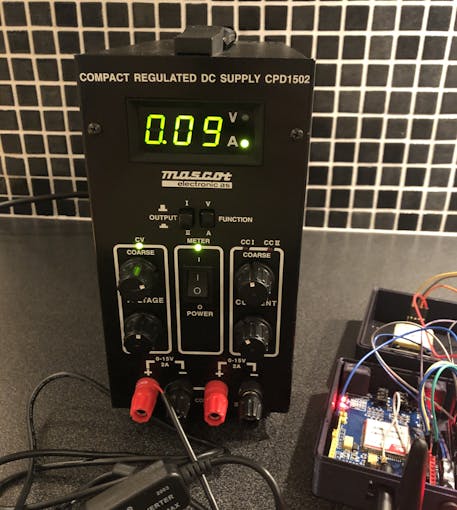
电源
Arduino 板无法提供足够的电源,因此我们必须使用外部电源。由于尖峰电流最高可达 2A,因此请确保使用可在 5V-9V DC 下提供至少 2A 电流的电源;它使用桶形5.5mm连接器。
电源选择器
DC 插孔旁边是电源选择器 .要使用外部电源,请按上图移动滑块。
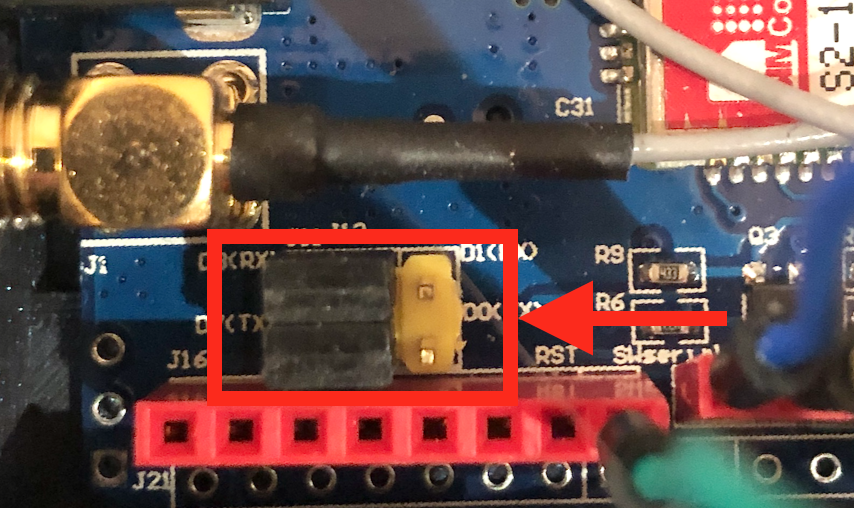
串行选择器
将开发板设置为使用 Software Serial 通过对齐跳线,如上图所示。
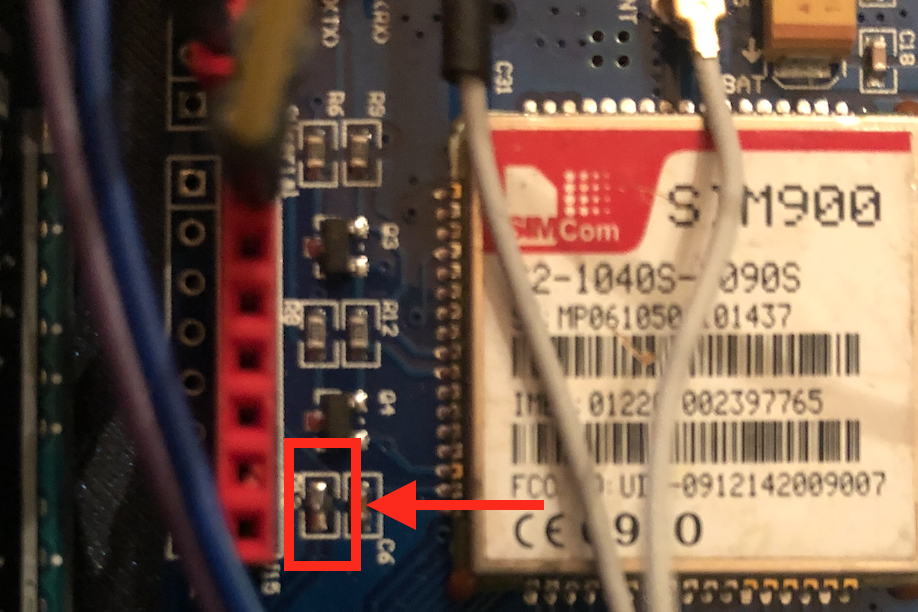
软件触发
无需每次都手动按下电源键,您可以在软件中打开/关闭 SIM900。为此,必须焊接名为 R13 的跳线。然后通过将 SIM900 引脚 #9 连接到 Arduino 引脚 #7(如原理图所示)为电路板供电。
如果保留“手动开机”功能,代码中的“SIM900power()”功能可以去掉。
解除SIM卡密码锁
请务必解除密码锁 使用前在 SIM 卡上。这可以通过将其插入任何普通手机并从适用的设置菜单中移除 pin 锁来完成。
另请注意,原理图中的 SIM900 模块可能看起来与实际电路板不同,但是,引脚布局正确是最重要的部分。
SIM900 固件版本 (重要!)
在芯片上加载正确版本的固件非常重要。这是因为在固件版本 B10 之前,不支持正确设置 HTTP POST 标头的命令之一。这意味着您至少需要 B10 或更高版本才能使 http 通信正常工作。具体来说,对于较低的固件版本,它将无法在 http 标头中设置“Content-type”。如果post请求中的content-type没有设置为“application/json”,会被服务器拒绝。
要检查您的固件版本,请使用以下 AT 命令:
AT+CGMR SIM900 芯片将在输出控制台中为您提供当前固件版本。将以下内容放在 setup() 部分的末尾以在启动时打印固件版本:
SIM900.println( F("AT+CGMR") ); 就我而言,它会显示这一点(在我更新之前):
修订版:1137B01SIM900M64_ST_AM 这是该芯片可能的最旧固件版本(“B01”),因此我更新到版本 B10:1137B10SIM900M64_ST .较新的固件也应该可以使用。
我不会在本指南中介绍如何更新固件,已经有一个很好的指南:SIM900 固件更新 - ACOPTEX(虽然过程有点痛苦)。
我不知道 SIM800 等其他芯片是否会出现这种情况,但是,这是一种较新的芯片,我认为它更有可能已经存在。
代码调整
要为您自己的项目调整代码,需要进行一些调整:
- 更改 APN(网络提供商)信息。
- 修改 thinger.io URL 以匹配您自己的 URL(该 URL 将更新请求链接到您自己的带有访问令牌的“bucket”)。这在“thinger.io 集成”一章中有介绍。
- 设置正确的时区。
- 设置短信通知的触发距离
- 设置(或禁用)短信通知文本。
- 设置通知的默认电话号码。
APN 提供商
void connectGPRS(){... SIM900.println( F("AT+SAPBR=3,1,\"APN\",\"TeleXXX\""));延迟(1000); updateSIM900();... 在connectGPRS()下 功能,您将找到网络提供商提供的 APN 名称,如上所示 “TeleXXX”。 将其替换为您自己的 APN 名称。
ATOKAT+CMGF=1OKAT+CNMI=1,2,0,0,0OKAT+SAPBR=3,1,"CONTYPE","GPRS"OKAT+SAPBR=3,1,"APN"," TeleXXX"OKAT+SAPBR=1,1OKAT+SAPBR=2,1+SAPBR:1,1,"36.57.240.233"OK 上图:连接正常时 connectGPRS() 函数的输出。所有命令都应返回“OK”状态。
时区
#define UTC_OFFSET 1 // 设置时区偏移,即 1 =UTC+1 在“定义”部分,根据您的要求设置时区。代码设置为UTC+1 .
短信通知
我已经设置了每 4000 公里的通知来清空我的油箱。我意识到大多数人都没有油箱,因此应将此通知更改为您想要的任何内容(或完全禁用)。
void loop() {... // 如果总距离超过 4000km,则发送短信通知 if (totalDistance> triggerDistance) { char sms_msg[160];字符距离TotalMsg[10]; itoa((totalDistance / 1000), distanceTotalMsg, 10); sprintf(sms_msg, "空水箱!当前距离:%skm", distanceTotalMsg); textMessage ="";总距离 =0; // 设置默认电话号码触发通知 number =DEFAULT_NUMBER;发送短信(sms_msg); } ...} 上图:触发通知的代码部分(在 main loop() 内)。
如果您不想要任何触发的通知,请注释掉/删除此部分。或者将文本更改为有用的内容。
一旦“里程表”(累计距离)达到“settings.txt”文件中设置的配置距离,就会触发通知。
默认电话号码
这是触发通知发送到的电话号码(因为通知没有要回复的“发件人”号码)
// 触发通知的电话号码#define DEFAULT_NUMBER "+4712345678" 等待串口连接
取消注释代码中的以下行也是一个好主意。这使得 Arduino 板等待串行连接变为活动状态,即用于调试的串行监视器。这样您就不会在串行线路变为活动状态之前错过代码开头的任何调试消息。
请记住在从外部电源为 Arduino 供电之前删除/注释该行,否则它将在无限循环中停止,直到它连接到 PC。
// while (!Serial); // 等待串口连接 - 对于 ATmega32u4 (Leonardo)
Thinger.io 集成
我不会详细介绍如何设置thinger.io,因为它非常简单;您必须创建一个帐户和一个“存储桶”以通过他们的网站接收数据,以及我们将连接到的“设备”。 “桶”是用于接收数据的数据库。 “设备”是我们代码的连接点,我们决定如何处理数据(在我们的例子中,填充“存储桶”数据库)。

使用您自己的名称和描述创建一个如上所示的“存储桶”。
现在,按照官方文档中的说明创建一个“HTTP 设备”:https://docs.thinger.io/quick-sart/devices/http-devices。
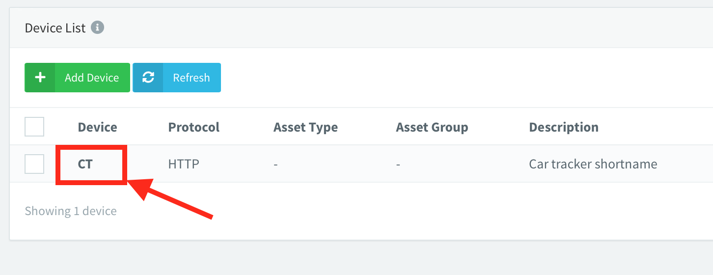
使用短 设备 姓名 .由于设备名称是生成授权密钥的算法的一部分,我发现较长的设备名称也会生成较长的授权密钥。问题?授权密钥很快就超过了用于从 Arduino 发送字符串的 256 个字符缓冲区。可能有一些更好的方法来解决这个问题,但我找到了保持设备名称简短并避免问题的最简单方法。
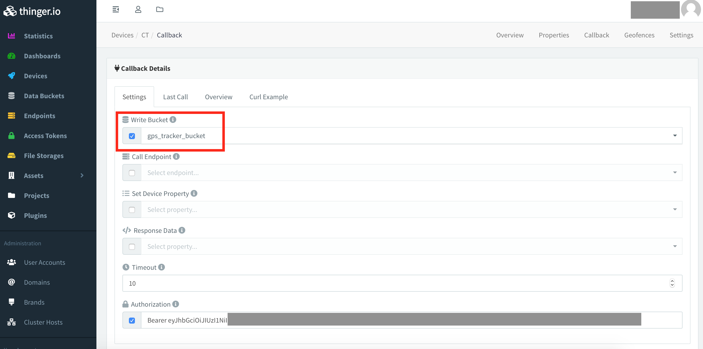
在设备的回调 > 设置 部分确保“写入存储桶”设置指向之前创建的存储桶。这告诉“设备”将传入的数据写入我们的数据库。
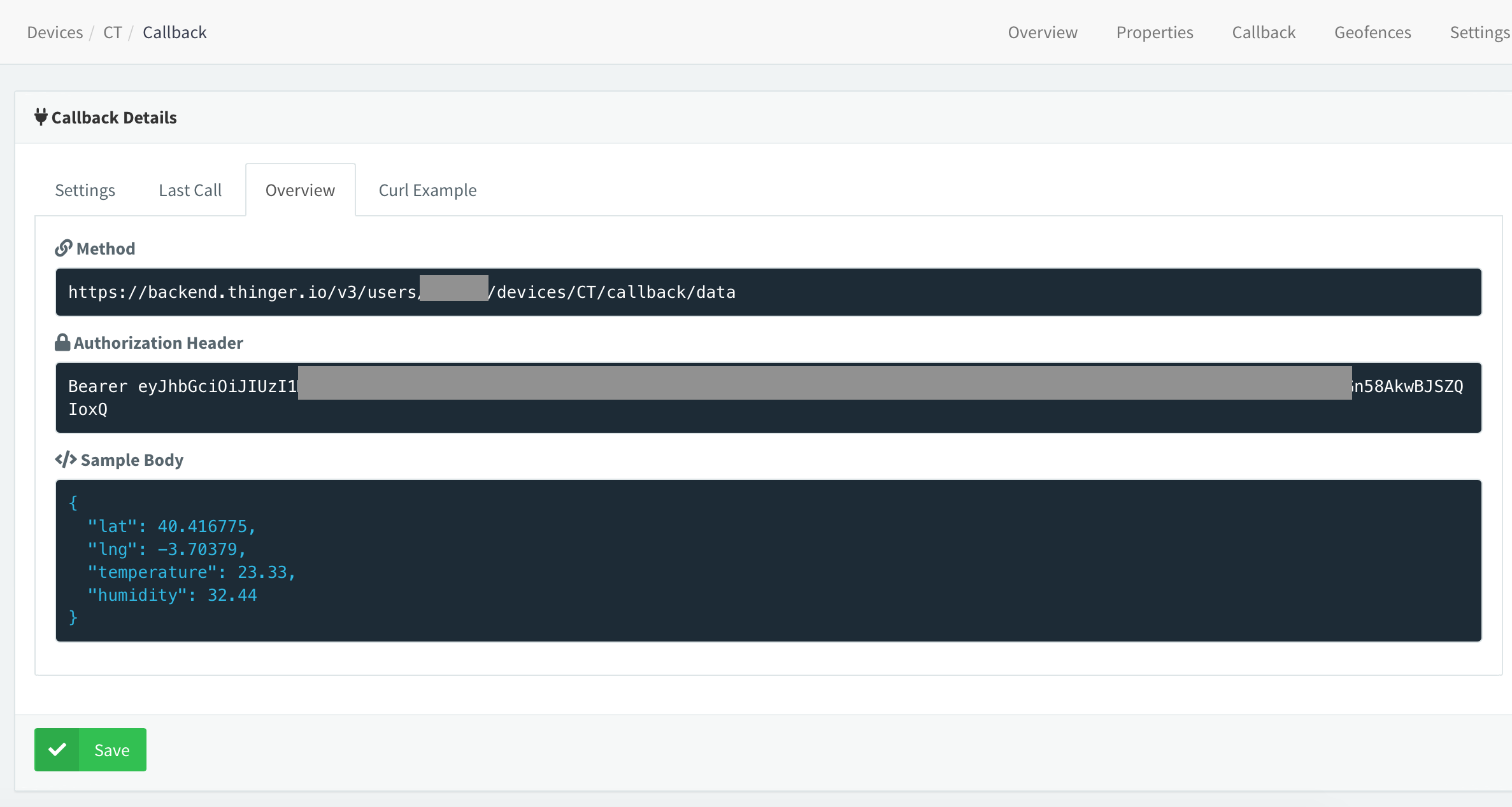
在设备的回调 > 概览 部分记下方法 网址 和授权标头 (不带关键字“Bearer”的长字符串)。
要将数据发送到 thinger.io,我们在 HTTP POST 请求中使用“授权 URL”。然后,您必须将代码中的 URL 和授权密钥替换为您自己的。
在 postDataThinger() 函数你会发现调用(实际授权密钥加扰):
SIM900.println( F("AT+HTTPPARA=\"URL\",\"http://backend.thinger.io/v3/users/tom/devices/CT/callback/data?authorization =eyJhbGciOiJIUzI1NiIsInR5cdfkjowiuerdf.sdfsdf.wekrjciI6InRvcm1vZCJ9.AR1gWvIZB9KmtI-5Z12YXKuchPTGn58AkwBJSZQIoxQ\"") ); 然后您必须替换网址 和授权 键 在您自己的代码中,按照上面提供的链接中的说明生成。
http://backend.thinger.io/... 默认情况下,生成的授权 URL 将为 https . SIM900没有 支持 SSL (至少我还没有让它工作),所以一定要改变“https ://" 到 "http://"。thinger API 也支持非 SSL 连接。这一点非常重要。如果你保持“https”,它将无法工作。当一切正常时,串行监视器应该给出“200 - OK”发送http post请求时回复。
AT命令"AT+HTTPACTION=1"之后 (发送 HTTP POST 请求)您应该在串行监视器中收到这样的回复:
+HTTPACTION:1,200,0 如果您收到“400 - 错误请求”回复或类似回复..
+HTTPACTION:0,400,51 .. URL 很可能有问题,例如“https”而不是“http”,“授权密钥”的语法错误等。当您收到“200 - OK”消息时,数据应显示在thinger存储桶中,如下所示。如果您没有前面提到的正确固件,您还会收到 400 -“错误请求”。
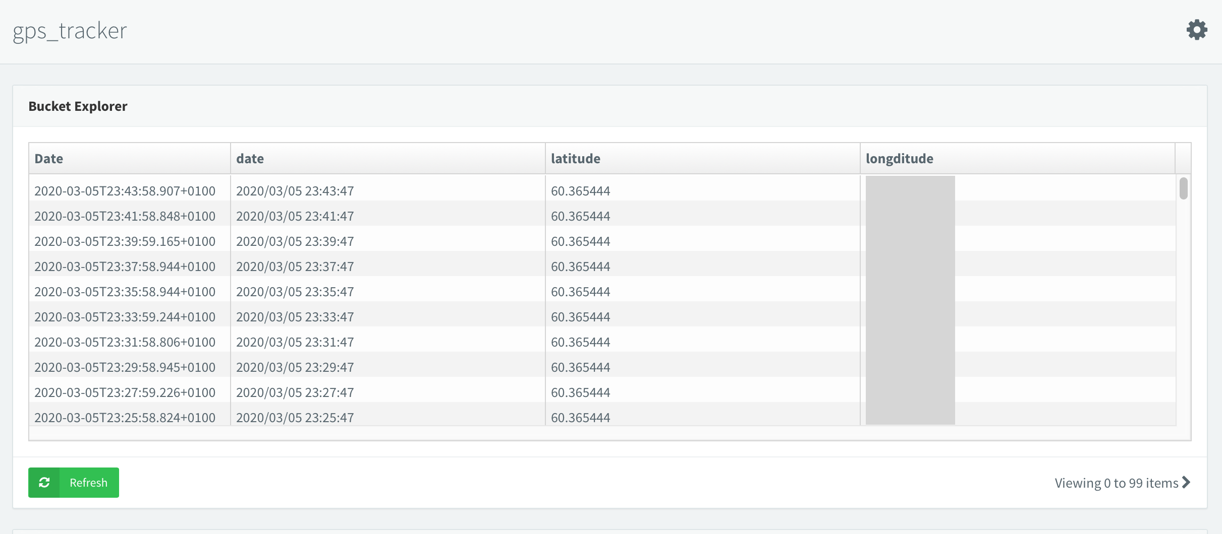
上图是数据到达后的存储桶视图(出于隐私原因进行了加扰)。内容(数据列)由代码中的HTTP POST请求语法设置,无需在thinger.io设置。
下面是 HTTP POST 请求的串行输出,因为它在一切正常时应该看起来。 +HTTPACTION:1, 200, 0 表示更新成功。
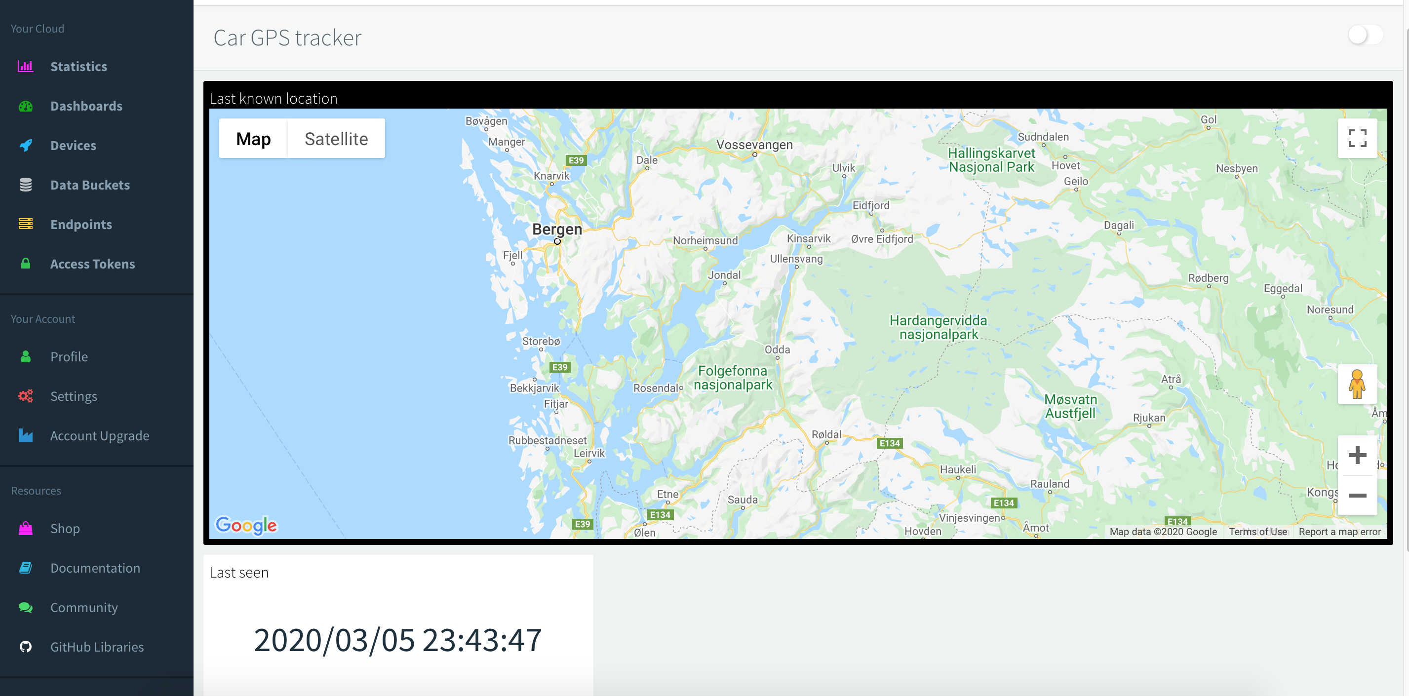
AT+HTTPINITOKAT+HTTPPARA="CID",1OKAT+HTTPPARA="URL","OKAT+HTTPPARA="CONTENT","application/json"OKAT+HTTPDATA=84,10000DOWNLOADOKAT+HTTPACTION=1OK+ HTTPACTION:1,200,0AT+HTTPTERMOK 仪表板 然后可以使用存储桶作为数据源使用地图小部件轻松地在thinger上进行设置。
需要更多数据?
您想推送比经度、纬度和日期/时间更多的数据吗?只需向 http 请求添加更多数据字段,如下所示。
格式为 { "field1 name" :field1, "field2 name" :field2, "field3 name" :field3 }
sprintf(httpContent, "{ \"longitude\" :%s , \"latitude\" :%s , \"date\" :\"%s %s\" }", tempstrLong, tempstrLat , 日期 1, 时间 1); 上面的 sprintf 命令编译发送给 thinger 的数据字符串。语法*非常*严格,您必须以完全相同的方式添加新数据字段。代码中给出了示例(评论部分)。一个好主意是记下将显示字符串的命令的串行监视器打印。然后添加“field4”等等..
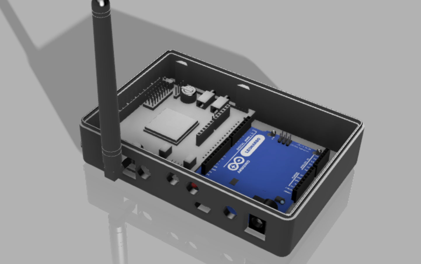
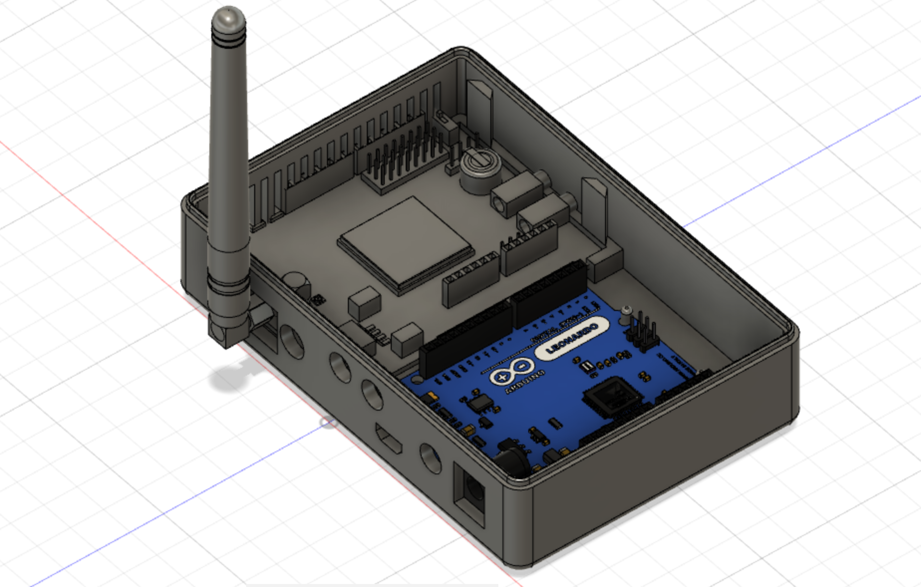
外壳
我附上了一个完整的 3D 可打印外壳。它旨在适合用于该项目的确切 PCB。安装使用M3螺丝。

 &wscript=max=6604-4bf5-b1ee-3713309f84fc_1_201_a_m1cY5Q4C5k.jpeg?>
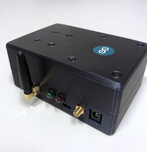
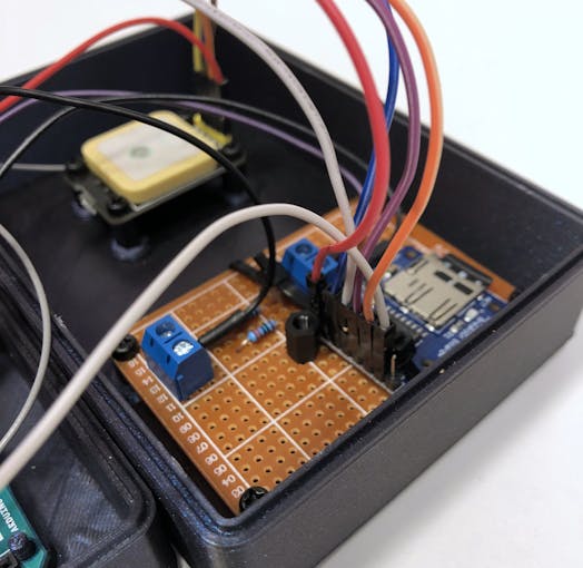
它设计用于 LED“电路”的 7x5cm 焊板,而不是面包板。如果使用面包板,只需使用一些胶水即可。 GPS 和焊接板(“面包板”)安装在顶部外壳中。使用小垫片以最好地将 PCB 安装在顶壳中。
我还将顶部外壳中的安装点保持牢固(无孔),以便在没有支撑的情况下更容易打印。用 3 毫米钻头打开这些。
它在没有支撑的情况下可以在 0.2 毫米上很好地打印。
连接到汽车电池/电源
可能有数百种方法可以做到这一点,所以我没有唯一的答案,也没有最好的答案;如何将其连接到汽车电池。这完全取决于您的应用程序,但我会快速描述我的解决方案。
我希望设备从汽车开始,因此不直接连接到电池(并在汽车关闭时消耗电力)。所以我已经将它连接到已经与汽车一起打开/关闭的“香烟插座”电路。如果您希望它即使在汽车熄火时也能在线,则必须找到一种方法将其连接到电池。对于大多数汽车,香烟插座随汽车关闭,但您必须自己检查。我不会显示我的确切接线,因为每辆车都会有所不同。 You can also place a battery pack in between to keep the device going for hours after the car has been switched off (or stolen..).
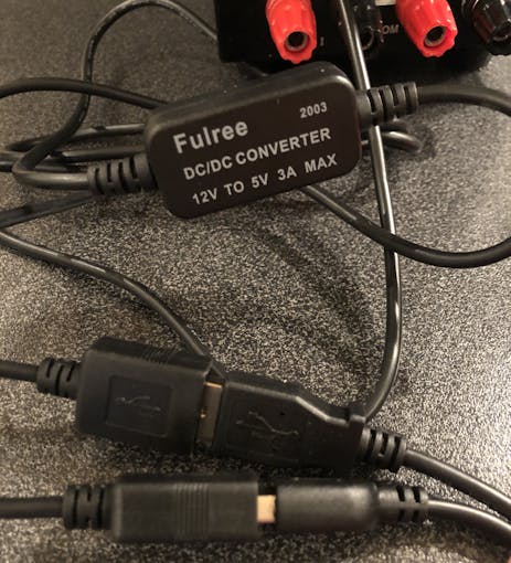
You can of course also just use an adapter, like one of those USB phone chargers, but that defeats my purpose of hiding it (in case the car gets stolen). We also have two power sources, the Arduino board and the SIM900 module. I used a "China cheap-o matic" step-down module, that converts from 12V-5V (the actual input range was said to be 9V-20V). It's probably not good quality, but has been working ok so far :)
The step-down module transforms the 12V input to 5V output to two USB female connectors. I then connected the Arduino- and SIM900 module to each of these USB outputs to power them. There are probably other and more "professional" solutions, but this was cheap and worked well enough.
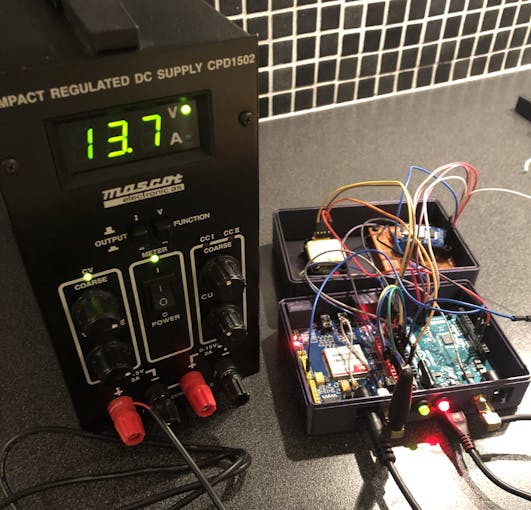
I have measured the power draw during GSM activity to around 110maH, so very little power consumption. It will probably draw more power in areas with poor GSM coverage.
Known issues
If an SMS command is received at the same time as the thinger.io http request is processed (while data is being pushed to thinger) the command will not be picked up by the software. In this case, you will not receive a SMS reply. Send a new command some seconds later and it will work again. I've not made a workaround for this, as its not a big problem. If someone should make a fix for this, please feel free to share.
Also, if the Arduino is started in an area without network coverage, it won't reconnect when the network is available again, as it only connects during startup. I might modify the code at some point to fix this, but at the moment it
代码
- GPS_tracker_Leonardo_v2.ino
GPS_tracker_Leonardo_v2.inoArduino
#include#include #include #include #include "PF.h"#include "PetitSerial.h"#define UTC_OFFSET 1 // set time zone offset, i.e. 1 =UTC+1#define TXPin 8 // SIM900 Tx pin#define RXPin 9 // SIM900 Rx pin#define PWRPin 7 // SIM900 software power pin// phone number for triggered notification#define DEFAULT_NUMBER "+4712345678"FATFS fs; // file system object - for reading SD card// GSM variablesString textMessage; // holds the last received text messageString number =DEFAULT_NUMBER; // phone number from last text messagechar sms_msg[160]; // holds the SMS reply text// location variablesfloat Lat =0, Long =0;boolean valid_location =false; // initial valid location flaguint8_t num_sat;NeoGPS::Location_t prevFix; // holds previous location for distance calculationNMEAGPS gps; // parses the GPS charactersgps_fix fix; // holds on to the latest valuesconst char *googlePrefix ="http://maps.google.com/maps?q=";const char *filename ="DIST.TXT";const char *settings ="SETTINGS.TXT";// time variablesNeoGPS::time_t timeFix; // time object for current gps fixchar datePrint[13];char timePrint[10];// distance tracking variablesfloat totalDistance =0; // in meters// triggerdistance (odometer notification) is read from SD card on initfloat triggerDistance =4000000;SoftwareSerial SIM900( TXPin, RXPin ); // SIM900 Tx &Rx is connected to Arduino #8 void setup() { pinMode(3, OUTPUT); pinMode(4,输出); digitalWrite(3, HIGH); // turn on power LED Serial.begin(9600); // serial monitor /* the "while (!serial)" construct below must only be enabled for debugging purposes when connected to a PC. If this is kept in the code the program will stop in a loop when connected to external power sources, as no serial connection will be established */ // while (!Serial); // wait for serial port to connect - for ATmega32u4 (Leonardo) SIM900.begin(9600); // SIM900 module on pins #8 and #9 gpsPort.begin(9600); // GPS receiver on Serial1 pins #0 and #1 - defined in GPSport.h // initialize the SD card and reads standard setting and accumulated distance initializeSD(); // power up SIM900 with software trigger SIM900power(); SIM900.println( F("AT") ); // Handshaking with SIM900 delay(500); SIM900.println( F("AT+CMGF=1") ); // Configuring TEXT mode delay(500); SIM900.println( F("AT+CNMI=1,2,0,0,0") ); // Decides how newly arrived SMS messages should be handled delay(500); connectGPRS();}void loop() { while (gps.available( gpsPort )) { fix =gps.read(); num_sat =fix.satellites; if (fix.valid.location) { digitalWrite(4, HIGH); // sets GPS lock LED Lat =fix.latitude(); Long =fix.longitude(); // saves the first "GPS lock" flag - we now have useful data if (Lat !=0 &&Long !=0 &&!valid_location) { valid_location =true; prevFix =fix.location; } } if (fix.valid.date &&fix.valid.time) { timeFix =fix.dateTime; updateTime(); } // update thinger.io and write values to SD card only for valid gps fix // typically at startup before gps has locked in coordinates first time if (valid_location) { // updates the distance travelled every 15 seconds static const unsigned long REFRESH_INTERVAL_UPD =15000; // 15 seconds static unsigned long lastRefreshTime =millis(); if (millis() - lastRefreshTime>=REFRESH_INTERVAL_UPD) { lastRefreshTime +=REFRESH_INTERVAL_UPD; // calculates distance between current and previous fix in meters float distanceDelta =prevFix.DistanceKm(fix.location) * 1000; // only update if distance is greater than 10 meters and less than 10km // 10km check is implemented to avoid erroneous data reading from GPS if (distanceDelta> 10 &&distanceDelta <10000) { totalDistance +=distanceDelta; } // reset the calculation point for next loop (set "previous" location) prevFix =fix.location; } // writes distance travelled to SD card every 2 minutes // uploads coordinates to thinger.io every 2 minutes static const unsigned long REFRESH_INTERVAL_WRITE_SD =120000UL; // 2 minutes static unsigned long lastRefreshTimeWriteSD =millis(); if (millis() - lastRefreshTimeWriteSD>=REFRESH_INTERVAL_WRITE_SD) { lastRefreshTimeWriteSD +=REFRESH_INTERVAL_WRITE_SD; // file write to SD card begin char buf[9]; dtostrf(totalDistance, 8, 0, buf); if (PF.open(filename)) Serial.println( F("error open file") ); while (1) { UINT nr; if (PF.writeFile(buf, sizeof(buf), &nr)) Serial.println( F("error write file") ); if (nr ==sizeof(buf)) { PF.writeFile( 0, 0, &nr); // finalize write operation by writing a null pointer break; } } // Petit FS has no "close" operation on file // next section transfers data to thinger.io IoT cloud with HTTP POST request. // only update thinger.io after first successful GPS lock char httpContent[60]; char tempstrLong[10]; char tempstrLat[10]; dtostrf(Lat, 2, 6, tempstrLat); dtostrf(Long, 2, 6, tempstrLong); // data fields to thinger.io bucket. Access to bucket is given through URL authorization in the post function. // format is { "field1 name" :field1 , "field2 name" :field2 , "field3 name" :field3 } with exact byte count. sprintf(httpContent, "{ \"longitude\":%s , \"latitude\":%s , \"date\":\"%s %s\" }", tempstrLong, tempstrLat, datePrint, timePrint); char httpdataLen[20]; // exact byte count for the content must be added to HTTPDATA // otherwise HTTP POST request is invalid, i.e. status 400 is retured. sprintf(httpdataLen, "AT+HTTPDATA=%i,10000", strlen(httpContent)); postDataThinger(httpdataLen, httpContent); } } } // send SMS notification if the total distance exceeds configured limit if (totalDistance> triggerDistance) { char distanceTotalMsg[10]; itoa( (totalDistance / 1000) , distanceTotalMsg, 10); sprintf(sms_msg, "Empty catchtank! Current distance:%skm", distanceTotalMsg); textMessage =""; number =DEFAULT_NUMBER; totalDistance =0; sendSMS(sms_msg); } updateSerial();}void updateSerial(){ // read incoming buffer. reads content of any text message if (SIM900.available()> 0) { textMessage =SIM900.readString(); } if (textMessage.indexOf("POS")>=0) { extractSenderNumber(); textMessage =""; char latPrint[10]; dtostrf(Lat, 5, 6, latPrint); char LonPrint[10]; dtostrf(Long, 5, 6, LonPrint); if (num_sat>=3 &&valid_location) { sprintf(sms_msg, "Current location:Lat:%s, Long:%s. %s%s,+%s\n", latPrint, LonPrint, googlePrefix, latPrint, LonPrint); } else if (num_sat <3 &&valid_location) { sprintf(sms_msg, "No gps fix. Last seen %s%sat:Lat:%s, Long:%s. %s%s,+%s\n", datePrint, timePrint, latPrint, LonPrint, googlePrefix, latPrint, LonPrint); } else if (!valid_location) { sprintf(sms_msg, "Tom not found. Maybe he is in North-Korea?"); } sendSMS(sms_msg); } // returns the current total accumulated distance if (textMessage.indexOf("GETKM")>=0 ) { char sms_msg[32]; char distanceTotalMsg[10]; itoa( (totalDistance / 1000) , distanceTotalMsg, 10); sprintf(sms_msg, "Current distance:%skm", distanceTotalMsg); textMessage =""; sendSMS(sms_msg); } // resets the distance counter to 0 if (textMessage.indexOf("RESETKM")>=0) { totalDistance =0; char sms_msg[] ="Acknowledge:distance reset"; textMessage =""; sendSMS(sms_msg); }}void SIM900power(){ // power up SIM900 board from pin #7 (default) -> 2sec. signal pinMode(PWRPin, OUTPUT); digitalWrite(PWRPin, LOW);延迟(1000); digitalWrite(PWRPin, HIGH);延迟(2000); digitalWrite(PWRPin, LOW); delay(15000); // give module time to boot}void updateSIM900(){ // empty incoming buffer from SIM900 with read() delay(500); while (SIM900.available()) { // outputs buffer to serial monitor if connected Serial.write(SIM900.read()); }}void extractSenderNumber(){ uint8_t startPos =textMessage.indexOf("+", 6); uint8_t endPos =textMessage.indexOf(","); number =textMessage.substring(startPos, endPos - 1);}void sendSMS(char *content){ // really crappy string conversion since I was too lazy to do proper // char handling in the first place. // SMS is returned to the sender number. char numberChar[number.length() + 1]; number.toCharArray(numberChar, number.length() + 1); char cmd_sms[50]; sprintf(cmd_sms, "AT+CMGS=%c%s%c", 0x22, numberChar, 0x22); SIM900.println(cmd_sms); updateSIM900(); SIM900.print(content); updateSIM900(); SIM900.write(0x1A);}void connectGPRS(){ SIM900.println( F("AT+SAPBR=3,1,\"CONTYPE\",\"GPRS\"") );延迟(1000); updateSIM900(); SIM900.println( F("AT+SAPBR=3,1,\"APN\",\"TeleXXX\"") );延迟(1000); updateSIM900(); SIM900.println( F("AT+SAPBR=1,1") );延迟(1000); updateSIM900(); SIM900.println( F("AT+SAPBR=2,1") );延迟(1000); updateSIM900();}void postDataThinger(char *httpDataLen, char* content){ SIM900.println( F("AT+HTTPINIT") );延迟(1000); updateSIM900(); SIM900.println( F("AT+HTTPPARA=\"CID\",1") );延迟(1000); updateSIM900(); SIM900.println( F("AT+HTTPPARA=\"URL\",\"http://backend.thinger.io/v3/users/tom/devices/CT/callback/data?authorization=eyJhbGciOiJIUzI1NiIsInR5cCI6lskjdflksjdfweruiowe19DVCIsInVzciI6InRvcm1vZCJ9.AR1gWvIZB9KmtI-5Z12YXKuchPTGn58AkwBJSZQIoxQ\"") );延迟(1000); updateSIM900(); SIM900.println( F("AT+HTTPPARA=\"CONTENT\",\"application/json\"") );延迟(1000); updateSIM900(); SIM900.println(httpDataLen);延迟(1000); updateSIM900(); SIM900.println(content);延迟(1000); updateSIM900(); SIM900.println( F("AT+HTTPACTION=1") );延迟(10000); updateSIM900(); SIM900.println( F("AT+HTTPTERM") );延迟(1000); updateSIM900();}// initialize SD card and retrieves stored distance valuevoid initializeSD(){ // first section read current distance from SD card char buf[10]; // buffer to hold retrieved distance value // Initialize SD card and file system. if (PF.begin(&fs)) Serial.println( F("error begin file") ); // Open file for read - saved accumulated total distance if (PF.open(filename)) Serial.println( F("error open file") ); while (1) { UINT nr; if (PF.readFile(buf, sizeof(buf), &nr)) Serial.println( F("error read file") ); if (nr ==sizeof(buf)) break; } // no close function for Petit FS. // retrieves stored distance value to program totalDistance =atof(buf); // second section read odometer notification trigger value char bufTrigger[10]; // buffer to hold trigger value if (PF.open(settings)) Serial.println( F("error open file") ); while (1) { UINT nr; if (PF.readFile(bufTrigger, sizeof(bufTrigger), &nr)) Serial.println( F("error read file") ); if (nr ==sizeof(bufTrigger)) break; } // retrieves odometer notification value triggerDistance =atof(bufTrigger);}// corrects time object with time zone offsetvoid updateTime(){ // set time from GPS data string setTime(timeFix.hours, timeFix.minutes, timeFix.seconds, timeFix.date, timeFix.month, timeFix.year); // calc current time zone time by offset value adjustTime(UTC_OFFSET * SECS_PER_HOUR); sprintf(datePrint, "%02d/%02d/%04d ", day(), month(), year()); sprintf(timePrint, "%02d:%02d:%02d ", hour(), minute(), second());}
定制零件和外壳
Top of casing for more space (taller). The mounting holes are closed and must be drilled after print (to make for easier printing)A compact version of the top casing (less space inside enclosure)Bottom part of casing - for SIM900 and Arduino board with cutouts for connectorsLocks SIM900 board in placeLocks SIM900 board in place (no mounting holes on SIM900 board)rename to "dist.txt" and place on SD card dist_1qOG9VMO2D.txtrename to "settings.txt" and place on SD card settings_iMpR6v81OB.txt示意图
制造工艺