

Arduino 和 MPU6050 加速度计和陀螺仪教程
在本教程中,我们将学习如何将 MPU6050 加速度计和陀螺仪传感器与 Arduino 一起使用。首先,我将解释 MPU6050 的工作原理以及如何从中读取数据,然后我们将做两个实际示例。
您可以观看以下视频或阅读下面的书面教程。
在第一个示例中,使用 Processing 开发环境,我们将对传感器方向进行 3D 可视化,在第二个示例中,我们将制作一个简单的自稳定平台或 DIY 云台。基于MPU6050的方位及其融合的加速度计和陀螺仪数据,我们控制三个舵机保持平台水平。
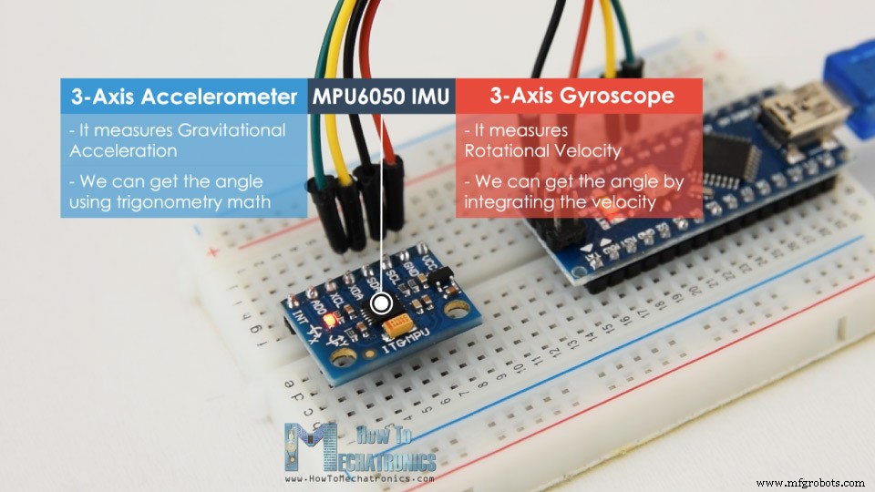
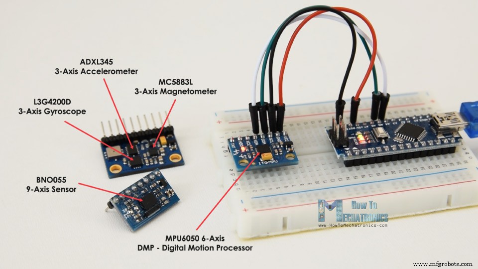
MPU6050 IMU将3轴加速度计和3轴陀螺仪集成在一个芯片上。
陀螺仪沿 X、Y 和 Z 轴测量旋转速度或角位置随时间的变化率。它使用 MEMS 技术和科里奥利效应进行测量,但有关它的更多详细信息,您可以查看我的特定 MEMS 传感器如何工作教程。陀螺仪的输出是以度/秒为单位的,所以为了得到角位置,我们只需要对角速度进行积分。
另一方面,MPU6050 加速度计测量加速度的方式与之前视频中对 ADXL345 加速度计传感器的说明相同。简而言之,它可以测量沿 3 个轴的重力加速度,并使用一些三角数学,我们可以计算出传感器定位的角度。因此,如果我们融合或结合加速度计和陀螺仪数据,我们可以获得关于传感器方向的非常准确的信息。
MPU6050 IMU也被称为六轴运动跟踪设备或6 DoF(六自由度)设备,因为它有6个输出,或3个加速度计输出和3个陀螺仪输出。
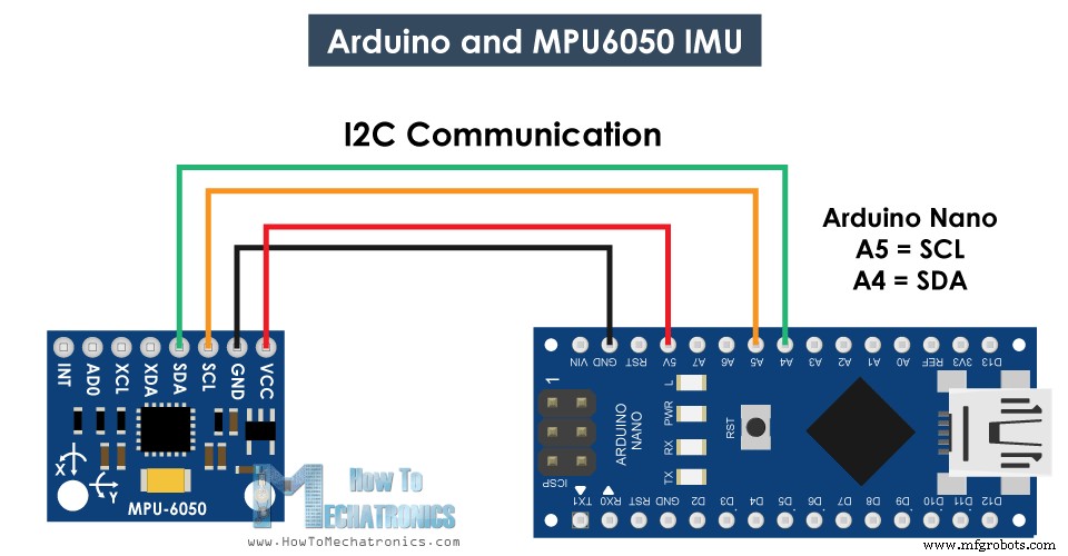
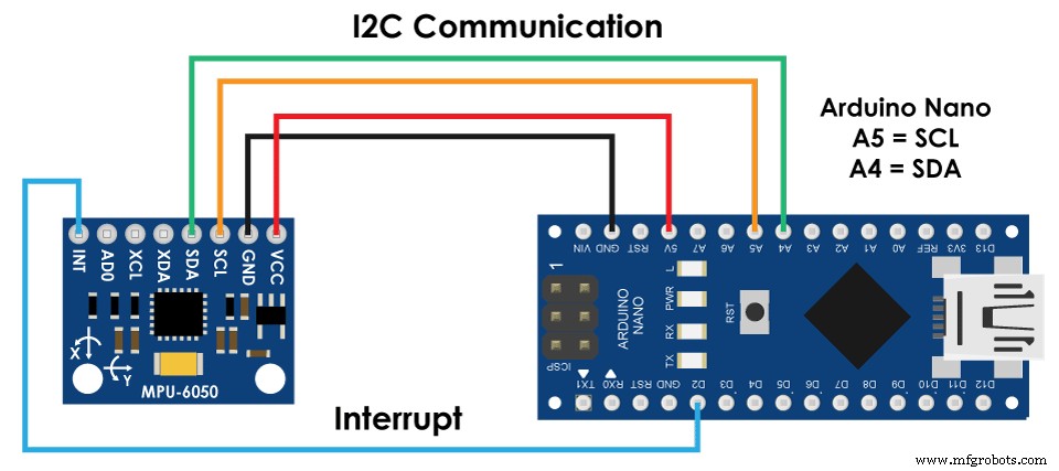
让我们看看如何使用 Arduino 连接和读取 MPU6050 传感器的数据。我们使用 I2C 协议与 Arduino 进行通信,因此我们只需要两根线来连接它,再加上两根用于供电的线。
您可以从以下链接获取本 Arduino 教程所需的组件:
这是用于从 MPU6050 传感器读取数据的 Arduino 代码。在代码下方你可以找到它的详细描述。
代码说明: 所以首先我们需要包含用于 I2C 通信的 Wire.h 库,并定义一些存储数据所需的变量。
在设置部分,我们需要初始化线库并通过电源管理寄存器重置传感器。为此,我们需要查看传感器的数据表,从中可以看到寄存器地址。
此外,如果需要,我们可以使用它们的配置寄存器为加速度计和陀螺仪选择满量程范围。在本例中,我们将使用默认的 +- 2g 范围的加速度计和 250 度/s 的陀螺仪范围,因此我将保留这部分代码的注释。
在循环部分,我们首先读取加速度计数据。每个轴的数据存储在两个字节或寄存器中,我们可以从传感器的数据表中看到这些寄存器的地址。
为了全部读取它们,我们从第一个寄存器开始,并使用 requestFrom() 函数请求读取 X、Y 和 Z 轴的所有 6 个寄存器。然后我们从每个寄存器中读取数据,因为输出是二进制补码,所以我们适当地组合它们以获得正确的值。
为了得到从-1g到+1g的输出值,适合计算角度,我们将输出除以之前选择的灵敏度。
最后,利用这两个公式,我们根据加速度计数据计算出横滚角和俯仰角。
接下来用同样的方法得到陀螺仪数据。
我们读取六个陀螺仪寄存器,将它们的数据适当组合,然后除以先前选择的灵敏度,以获得以度/秒为单位的输出。
在这里你可以注意到我用一些小的计算误差值纠正了输出值,我将在一分钟内解释我们如何得到它们。因此,由于输出以每秒度数为单位,现在我们需要将它们与时间相乘以获得度数。使用millis()函数在每次读取迭代之前捕获时间值。
最后,我们使用互补滤波器融合加速度计和陀螺仪数据。在这里,我们采用了 96% 的陀螺仪数据,因为它非常准确并且不受外力的影响。陀螺仪的缺点是它会漂移,或者随着时间的推移在输出中引入误差。因此,从长远来看,我们使用加速度计的数据,在这种情况下为 4%,足以消除陀螺仪漂移误差。
但是,由于我们无法从加速度计数据中计算出 Yaw,因此我们无法在其上实现互补滤波器。
在我们看结果之前,让我快速解释一下如何获得纠错值。为了计算这些误差,我们可以在传感器处于平坦静止位置时调用 calculate_IMU_error() 自定义函数。在这里,我们为所有输出读取 200 个读数,将它们相加并除以 200。由于我们将传感器保持在平坦静止位置,因此预期输出值应该为 0。因此,通过此计算,我们可以得到传感器的平均误差制作。
我们只需在串行监视器上打印这些值,一旦我们知道它们,就可以在代码中实现它们,如前所示,用于滚动和俯仰计算,以及 3 个陀螺仪输出。
最后,使用 Serial.print 函数,我们可以在串口监视器上打印 Roll、Pitch 和 Yaw 值,看看传感器是否正常工作。
接下来,为了制作 3D 可视化示例,我们只需要在 Processing 开发环境中接受 Arduino 通过串口发送的数据。这是完整的处理代码:
在这里,我们从 Arduino 读取传入数据并将其放入适当的 Roll、Pitch 和 Yaw 变量中。在主绘制循环中,我们使用这些值来旋转 3D 对象,在本例中,这是一个带有特定颜色和文本的简单框。
如果我们运行该草图,我们可以看到 MPU6050 传感器在跟踪方向方面的表现如何。 3D 物体可以非常准确地跟踪传感器的方向,而且反应灵敏。
正如我所提到的,唯一的缺点是偏航会随着时间的推移而漂移,因为我们不能使用互补滤波器。为了改善这一点,我们需要使用一个额外的传感器。这通常是一个磁力计,可以用作陀螺仪偏航漂移的长期校正。不过,MPU6050其实有一个功能叫Digital Motion Processor,用于板载数据计算,可以消除Yaw漂移。
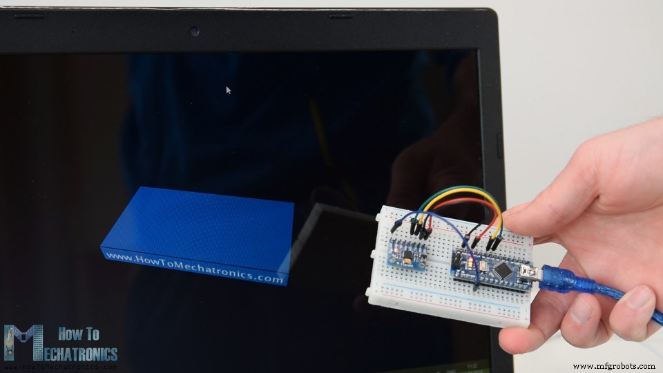
这是使用数字运动处理器的相同 3D 示例。我们可以看到方向跟踪现在有多准确,没有偏航漂移。板载处理器还可以计算和输出四元数,用于在三个维度上表示对象的方向和旋转。在这个例子中,我们实际上使用四元数来表示方向,它也不会受到使用欧拉角时发生的万向锁的影响。
然而,从传感器获取这些数据比我们之前解释的要复杂一些。首先,我们需要将额外的电线连接到 Arduino 数字引脚。这是一个中断引脚,用于从 MPU6050 读取该数据类型。
代码也有点复杂,所以我们将使用 Jeff Rowberg 的 i2cdevlib 库。该库可以从 GitHub 下载,我将在网站文章中包含一个链接。
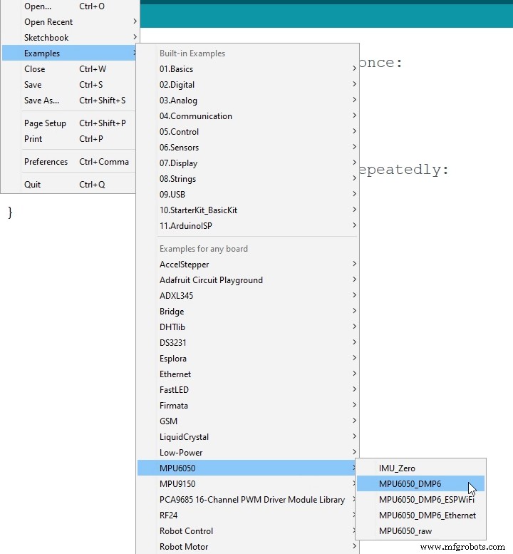
安装库后,我们可以从库中打开 MPU6050_DMP6 示例。这个例子很好地解释了每一行的注释。
在这里,我们可以选择我们想要的输出类型,四元数、欧拉角、偏航、俯仰和滚动、加速度值或 3D 可视化的四元数。该库还包括 3D 可视化示例的处理草图。我只是修改它以获得与前面示例中一样的盒子形状。这是与 MPU6050_DPM6 示例一起使用的 3D 可视化处理代码,用于选定的“OUTPUT_TEAPOT”输出:
所以在这里使用 serialEvent() 函数我们接收来自 Arduino 的四元数,在主绘制循环中我们使用它们来旋转 3D 对象。如果我们运行这个草图,我们可以看到四元数对于在三个维度上旋转物体是多么的好。
为了不超出本教程的内容,我将第二个示例,即 DIY Arduino 万向节或自稳定平台放在了另一篇文章中。
随时在下面的评论部分提出与本教程相关的任何问题,也不要忘记查看我收集的 Arduino 项目。概览
工作原理
Arduino 和 MPU6050
MPU6050 Arduino代码
/*
   Arduino and MPU6050 Accelerometer and Gyroscope Sensor Tutorial
   by Dejan, https://howtomechatronics.com
*/
#include <Wire.h>
const int MPU = 0x68; // MPU6050 I2C address
float AccX, AccY, AccZ;
float GyroX, GyroY, GyroZ;
float accAngleX, accAngleY, gyroAngleX, gyroAngleY, gyroAngleZ;
float roll, pitch, yaw;
float AccErrorX, AccErrorY, GyroErrorX, GyroErrorY, GyroErrorZ;
float elapsedTime, currentTime, previousTime;
int c = 0;
void setup() {
  Serial.begin(19200);
  Wire.begin();                      // Initialize comunication
  Wire.beginTransmission(MPU);       // Start communication with MPU6050 // MPU=0x68
  Wire.write(0x6B);                  // Talk to the register 6B
  Wire.write(0x00);                  // Make reset - place a 0 into the 6B register
  Wire.endTransmission(true);        //end the transmission
  /*
  // Configure Accelerometer Sensitivity - Full Scale Range (default +/- 2g)
  Wire.beginTransmission(MPU);
  Wire.write(0x1C);                  //Talk to the ACCEL_CONFIG register (1C hex)
  Wire.write(0x10);                  //Set the register bits as 00010000 (+/- 8g full scale range)
  Wire.endTransmission(true);
  // Configure Gyro Sensitivity - Full Scale Range (default +/- 250deg/s)
  Wire.beginTransmission(MPU);
  Wire.write(0x1B);                   // Talk to the GYRO_CONFIG register (1B hex)
  Wire.write(0x10);                   // Set the register bits as 00010000 (1000deg/s full scale)
  Wire.endTransmission(true);
  delay(20);
  */
  // Call this function if you need to get the IMU error values for your module
  calculate_IMU_error();
  delay(20);
}
void loop() {
  // === Read acceleromter data === //
  Wire.beginTransmission(MPU);
  Wire.write(0x3B); // Start with register 0x3B (ACCEL_XOUT_H)
  Wire.endTransmission(false);
  Wire.requestFrom(MPU, 6, true); // Read 6 registers total, each axis value is stored in 2 registers
  //For a range of +-2g, we need to divide the raw values by 16384, according to the datasheet
  AccX = (Wire.read() << 8 | Wire.read()) / 16384.0; // X-axis value
  AccY = (Wire.read() << 8 | Wire.read()) / 16384.0; // Y-axis value
  AccZ = (Wire.read() << 8 | Wire.read()) / 16384.0; // Z-axis value
  // Calculating Roll and Pitch from the accelerometer data
  accAngleX = (atan(AccY / sqrt(pow(AccX, 2) + pow(AccZ, 2))) * 180 / PI) - 0.58; // AccErrorX ~(0.58) See the calculate_IMU_error()custom function for more details
  accAngleY = (atan(-1 * AccX / sqrt(pow(AccY, 2) + pow(AccZ, 2))) * 180 / PI) + 1.58; // AccErrorY ~(-1.58)
  // === Read gyroscope data === //
  previousTime = currentTime;        // Previous time is stored before the actual time read
  currentTime = millis();            // Current time actual time read
  elapsedTime = (currentTime - previousTime) / 1000; // Divide by 1000 to get seconds
  Wire.beginTransmission(MPU);
  Wire.write(0x43); // Gyro data first register address 0x43
  Wire.endTransmission(false);
  Wire.requestFrom(MPU, 6, true); // Read 4 registers total, each axis value is stored in 2 registers
  GyroX = (Wire.read() << 8 | Wire.read()) / 131.0; // For a 250deg/s range we have to divide first the raw value by 131.0, according to the datasheet
  GyroY = (Wire.read() << 8 | Wire.read()) / 131.0;
  GyroZ = (Wire.read() << 8 | Wire.read()) / 131.0;
  // Correct the outputs with the calculated error values
  GyroX = GyroX + 0.56; // GyroErrorX ~(-0.56)
  GyroY = GyroY - 2; // GyroErrorY ~(2)
  GyroZ = GyroZ + 0.79; // GyroErrorZ ~ (-0.8)
  // Currently the raw values are in degrees per seconds, deg/s, so we need to multiply by sendonds (s) to get the angle in degrees
  gyroAngleX = gyroAngleX + GyroX * elapsedTime; // deg/s * s = deg
  gyroAngleY = gyroAngleY + GyroY * elapsedTime;
  yaw =  yaw + GyroZ * elapsedTime;
  // Complementary filter - combine acceleromter and gyro angle values
  roll = 0.96 * gyroAngleX + 0.04 * accAngleX;
  pitch = 0.96 * gyroAngleY + 0.04 * accAngleY;

  // Print the values on the serial monitor
  Serial.print(roll);
  Serial.print("/");
  Serial.print(pitch);
  Serial.print("/");
  Serial.println(yaw);
}
void calculate_IMU_error() {
  // We can call this funtion in the setup section to calculate the accelerometer and gyro data error. From here we will get the error values used in the above equations printed on the Serial Monitor.
  // Note that we should place the IMU flat in order to get the proper values, so that we then can the correct values
  // Read accelerometer values 200 times
  while (c < 200) {
    Wire.beginTransmission(MPU);
    Wire.write(0x3B);
    Wire.endTransmission(false);
    Wire.requestFrom(MPU, 6, true);
    AccX = (Wire.read() << 8 | Wire.read()) / 16384.0 ;
    AccY = (Wire.read() << 8 | Wire.read()) / 16384.0 ;
    AccZ = (Wire.read() << 8 | Wire.read()) / 16384.0 ;
    // Sum all readings
    AccErrorX = AccErrorX + ((atan((AccY) / sqrt(pow((AccX), 2) + pow((AccZ), 2))) * 180 / PI));
    AccErrorY = AccErrorY + ((atan(-1 * (AccX) / sqrt(pow((AccY), 2) + pow((AccZ), 2))) * 180 / PI));
    c++;
  }
  //Divide the sum by 200 to get the error value
  AccErrorX = AccErrorX / 200;
  AccErrorY = AccErrorY / 200;
  c = 0;
  // Read gyro values 200 times
  while (c < 200) {
    Wire.beginTransmission(MPU);
    Wire.write(0x43);
    Wire.endTransmission(false);
    Wire.requestFrom(MPU, 6, true);
    GyroX = Wire.read() << 8 | Wire.read();
    GyroY = Wire.read() << 8 | Wire.read();
    GyroZ = Wire.read() << 8 | Wire.read();
    // Sum all readings
    GyroErrorX = GyroErrorX + (GyroX / 131.0);
    GyroErrorY = GyroErrorY + (GyroY / 131.0);
    GyroErrorZ = GyroErrorZ + (GyroZ / 131.0);
    c++;
  }
  //Divide the sum by 200 to get the error value
  GyroErrorX = GyroErrorX / 200;
  GyroErrorY = GyroErrorY / 200;
  GyroErrorZ = GyroErrorZ / 200;
  // Print the error values on the Serial Monitor
  Serial.print("AccErrorX: ");
  Serial.println(AccErrorX);
  Serial.print("AccErrorY: ");
  Serial.println(AccErrorY);
  Serial.print("GyroErrorX: ");
  Serial.println(GyroErrorX);
  Serial.print("GyroErrorY: ");
  Serial.println(GyroErrorY);
  Serial.print("GyroErrorZ: ");
  Serial.println(GyroErrorZ);
}Code language: Arduino (arduino)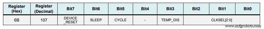
// Configure Accelerometer Sensitivity - Full Scale Range (default +/- 2g)
  Wire.beginTransmission(MPU);
  Wire.write(0x1C);                  //Talk to the ACCEL_CONFIG register (1C hex)
  Wire.write(0x10);                  //Set the register bits as 00010000 (+/- 8g full scale range)
  Wire.endTransmission(true);
  // Configure Gyro Sensitivity - Full Scale Range (default +/- 250deg/s)
  Wire.beginTransmission(MPU);
  Wire.write(0x1B);                   // Talk to the GYRO_CONFIG register (1B hex)
  Wire.write(0x10);                   // Set the register bits as 00010000 (1000deg/s full scale)
  Wire.endTransmission(true);
  */Code language: Arduino (arduino)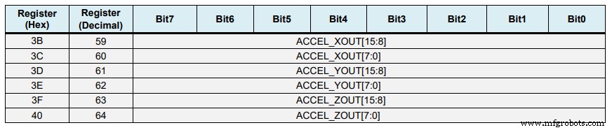
// === Read acceleromter data === //
  Wire.beginTransmission(MPU);
  Wire.write(0x3B); // Start with register 0x3B (ACCEL_XOUT_H)
  Wire.endTransmission(false);
  Wire.requestFrom(MPU, 6, true); // Read 6 registers total, each axis value is stored in 2 registers
  //For a range of +-2g, we need to divide the raw values by 16384, according to the datasheet
  AccX = (Wire.read() << 8 | Wire.read()) / 16384.0; // X-axis value
  AccY = (Wire.read() << 8 | Wire.read()) / 16384.0; // Y-axis value
  AccZ = (Wire.read() << 8 | Wire.read()) / 16384.0; // Z-axis valueCode language: Arduino (arduino)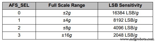
// Calculating Roll and Pitch from the accelerometer data
  accAngleX = (atan(AccY / sqrt(pow(AccX, 2) + pow(AccZ, 2))) * 180 / PI) - 0.58; // AccErrorX ~(0.58) See the calculate_IMU_error()custom function for more details
  accAngleY = (atan(-1 * AccX / sqrt(pow(AccY, 2) + pow(AccZ, 2))) * 180 / PI) + 1.58; // AccErrorY ~(-1.58)Code language: Arduino (arduino)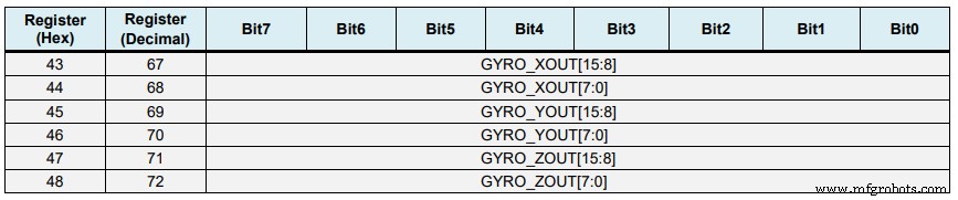
// === Read gyroscope data === //
  previousTime = currentTime;        // Previous time is stored before the actual time read
  currentTime = millis();            // Current time actual time read
  elapsedTime = (currentTime - previousTime) / 1000; // Divide by 1000 to get seconds
  Wire.beginTransmission(MPU);
  Wire.write(0x43); // Gyro data first register address 0x43
  Wire.endTransmission(false);
  Wire.requestFrom(MPU, 6, true); // Read 4 registers total, each axis value is stored in 2 registers
  GyroX = (Wire.read() << 8 | Wire.read()) / 131.0; // For a 250deg/s range we have to divide first the raw value by 131.0, according to the datasheet
  GyroY = (Wire.read() << 8 | Wire.read()) / 131.0;
  GyroZ = (Wire.read() << 8 | Wire.read()) / 131.0;Code language: Arduino (arduino)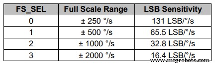
// Correct the outputs with the calculated error values
  GyroX = GyroX + 0.56; // GyroErrorX ~(-0.56)
  GyroY = GyroY - 2; // GyroErrorY ~(2)
  GyroZ = GyroZ + 0.79; // GyroErrorZ ~ (-0.8)
  // Currently the raw values are in degrees per seconds, deg/s, so we need to multiply by sendonds (s) to get the angle in degrees
  gyroAngleX = gyroAngleX + GyroX * elapsedTime; // deg/s * s = deg
  gyroAngleY = gyroAngleY + GyroY * elapsedTime;
yaw = yaw + GyroZ * elapsedTime;Code language: Arduino (arduino)// Complementary filter - combine acceleromter and gyro angle values
roll = 0.96 * gyroAngleX + 0.04 * accAngleX;
pitch = 0.96 * gyroAngleY + 0.04 * accAngleY;Code language: Arduino (arduino)void calculate_IMU_error() {
// We can call this funtion in the setup section to calculate the accelerometer and gyro data error. From here we will get the error values used in the above equations printed on the Serial Monitor.
// Note that we should place the IMU flat in order to get the proper values, so that we then can the correct values
// Read accelerometer values 200 times
while (c < 200) {
Wire.beginTransmission(MPU);
Wire.write(0x3B);
Wire.endTransmission(false);
Wire.requestFrom(MPU, 6, true);
AccX = (Wire.read() << 8 | Wire.read()) / 16384.0 ;
AccY = (Wire.read() << 8 | Wire.read()) / 16384.0 ;
AccZ = (Wire.read() << 8 | Wire.read()) / 16384.0 ;
// Sum all readings
AccErrorX = AccErrorX + ((atan((AccY) / sqrt(pow((AccX), 2) + pow((AccZ), 2))) * 180 / PI));
AccErrorY = AccErrorY + ((atan(-1 * (AccX) / sqrt(pow((AccY), 2) + pow((AccZ), 2))) * 180 / PI));
c++;
}
//Divide the sum by 200 to get the error value
AccErrorX = AccErrorX / 200;
AccErrorY = AccErrorY / 200;
c = 0;
// Read gyro values 200 times
while (c < 200) {
Wire.beginTransmission(MPU);
Wire.write(0x43);
Wire.endTransmission(false);
Wire.requestFrom(MPU, 6, true);
GyroX = Wire.read() << 8 | Wire.read();
GyroY = Wire.read() << 8 | Wire.read();
GyroZ = Wire.read() << 8 | Wire.read();
// Sum all readings
GyroErrorX = GyroErrorX + (GyroX / 131.0);
GyroErrorY = GyroErrorY + (GyroY / 131.0);
GyroErrorZ = GyroErrorZ + (GyroZ / 131.0);
c++;
}
//Divide the sum by 200 to get the error value
GyroErrorX = GyroErrorX / 200;
GyroErrorY = GyroErrorY / 200;
GyroErrorZ = GyroErrorZ / 200;
// Print the error values on the Serial Monitor
Serial.print("AccErrorX: ");
Serial.println(AccErrorX);
Serial.print("AccErrorY: ");
Serial.println(AccErrorY);
Serial.print("GyroErrorX: ");
Serial.println(GyroErrorX);
Serial.print("GyroErrorY: ");
Serial.println(GyroErrorY);
Serial.print("GyroErrorZ: ");
Serial.println(GyroErrorZ);
}Code language: Arduino (arduino)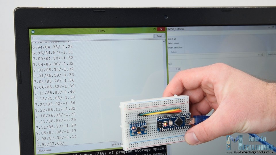
MPU6050 方向跟踪 - 3D 可视化
/*
    Arduino and MPU6050 IMU - 3D Visualization Example
     by Dejan, https://howtomechatronics.com
*/
import processing.serial.*;
import java.awt.event.KeyEvent;
import java.io.IOException;
Serial myPort;
String data="";
float roll, pitch,yaw;
void setup() {
  size (2560, 1440, P3D);
  myPort = new Serial(this, "COM7", 19200); // starts the serial communication
  myPort.bufferUntil('\n');
}
void draw() {
  translate(width/2, height/2, 0);
  background(233);
  textSize(22);
  text("Roll: " + int(roll) + "     Pitch: " + int(pitch), -100, 265);
  // Rotate the object
  rotateX(radians(-pitch));
  rotateZ(radians(roll));
  rotateY(radians(yaw));

  // 3D 0bject
  textSize(30);
  fill(0, 76, 153);
  box (386, 40, 200); // Draw box
  textSize(25);
  fill(255, 255, 255);
  text("www.HowToMechatronics.com", -183, 10, 101);
  //delay(10);
  //println("ypr:\t" + angleX + "\t" + angleY); // Print the values to check whether we are getting proper values
}
// Read data from the Serial Port
void serialEvent (Serial myPort) {
  // reads the data from the Serial Port up to the character '.' and puts it into the String variable "data".
  data = myPort.readStringUntil('\n');
  // if you got any bytes other than the linefeed:
  if (data != null) {
    data = trim(data);
    // split the string at "/"
    String items[] = split(data, '/');
    if (items.length > 1) {
      //--- Roll,Pitch in degrees
      roll = float(items[0]);
      pitch = float(items[1]);
      yaw = float(items[2]);
    }
  }
}Code language: Arduino (arduino)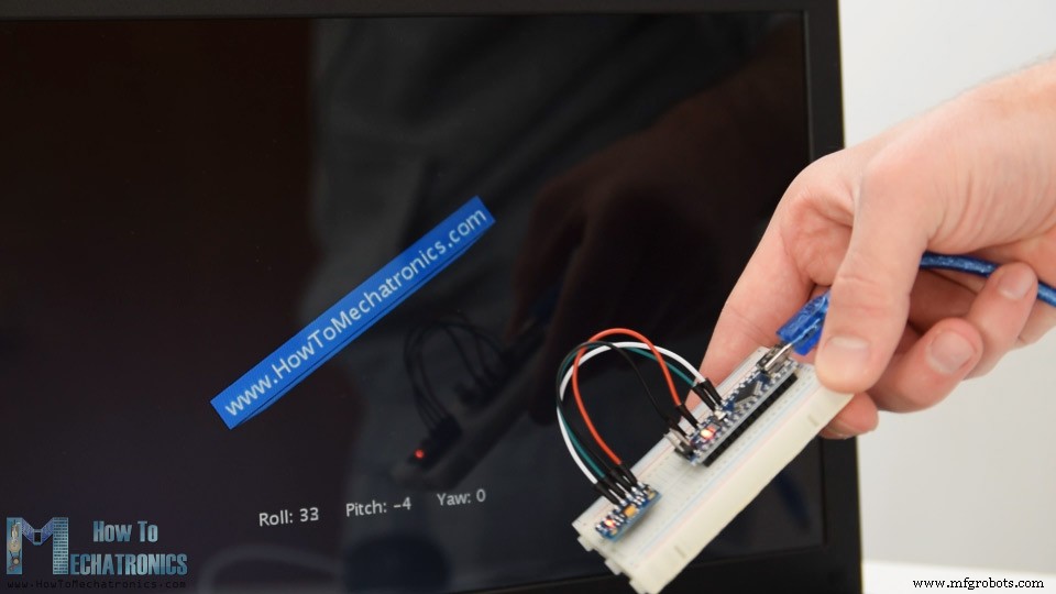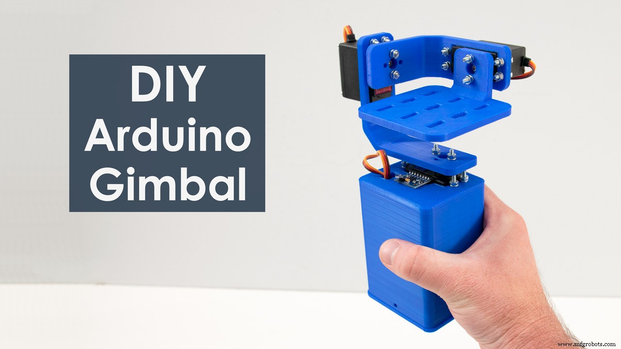
制造工艺