

如何使用 Arduino 和 ADXL345 加速度计跟踪方向
在本教程中,我们将学习如何使用 Arduino 和 ADXL345 加速度计传感器测量角度和轨道方向。您可以观看以下视频或阅读下面的书面教程了解更多详情。
首先,我将解释传感器的工作原理以及如何从中读取数据,然后使用 Processing 开发环境,我们将对加速度计方向进行 3D 可视化。
首先,让我们看一下 ADXL345 传感器的工作原理。这是一个 3 轴加速度计,可以测量静态和动态加速度力。地球万有引力是静力的典型例子,而动力可以由振动、运动等产生。
加速度的测量单位是米每秒平方 (m/s^2)。但是,加速度计传感器通常以“g”或重力表示测量值。一个“g”是地球引力的值,等于 9.8 米每秒平方。
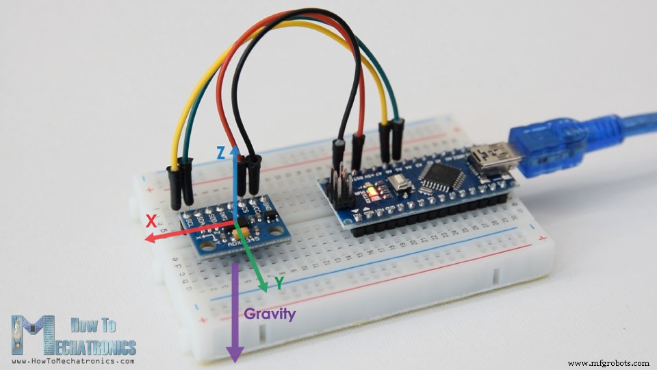
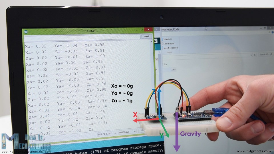
因此,如果我们有一个平放的加速度计,其 Z 轴指向上方,与重力相反,传感器的 Z 轴输出将为 1g。另一方面,X 和 Y 输出将为零,因为重力垂直于这些轴,根本不影响它们。
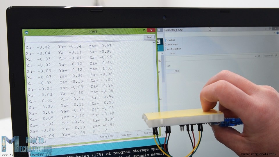
如果我们将传感器倒置,则 Z 轴输出将为 -1 g。这意味着传感器的输出由于其重力方向可以从 -1g 变化到 +1g。
所以根据这些数据并使用一些三角数学,我们可以计算出传感器所在的角度。
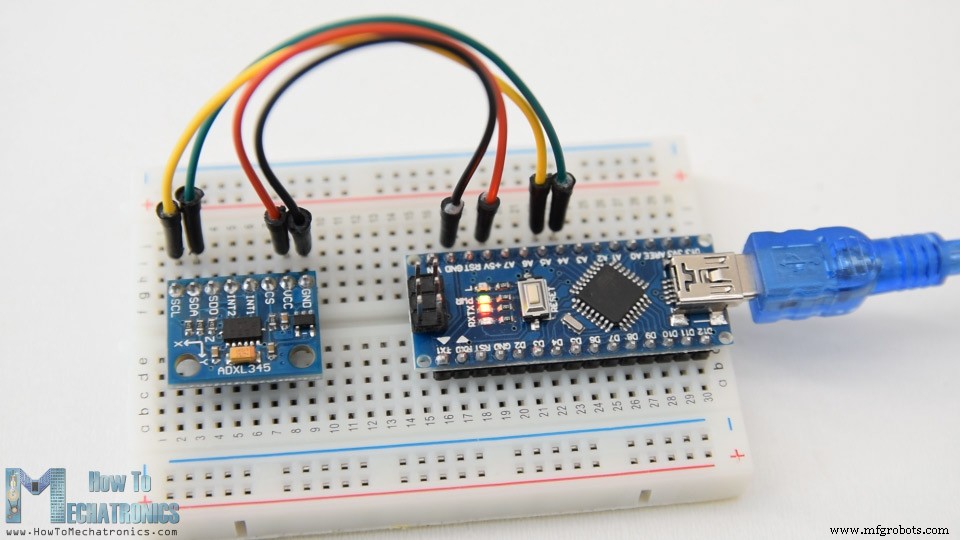
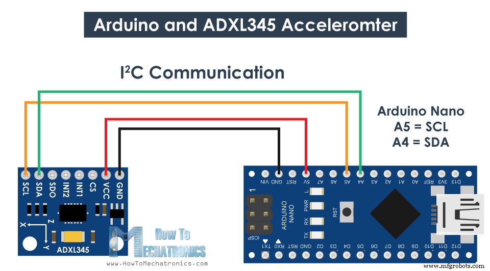
好的,现在让我们看看如何使用 Arduino 读取 ADXL345 加速度计数据。该传感器使用 I2C 协议与 Arduino 进行通信,因此我们只需要两根线来连接它,再加上两根线来为其供电。
您可以从以下链接获取本 Arduino 教程所需的组件:
这是读取 ADXL345 加速度计数据的 Arduino 代码。
说明: 所以首先我们需要包含用于 I2C 通信的 Wire.h 库。如果您想了解更多关于 I2C 通信如何工作以及如何与 Arduino 一起使用的信息,您可以查看我的其他详细教程。
每个使用 I2C 通信的设备都有一个唯一的 I2C 地址,该地址可以在传感器的数据表(ADXL345 数据表)中找到。因此,一旦我们定义了三个输出的地址和变量,在设置部分,我们首先需要初始化线库,然后将加速度计设置为测量模式。为了做到这一点,如果我们再看一下数据表,我们可以看到我们需要将 POWER_CTL 寄存器的位 D3 设置为高。
因此,使用 beginTransmission() 函数开始通信,然后使用 write() 函数告诉我们要访问哪个寄存器,然后再次使用 write() 函数将 D3 位设置为高,将数字 8 写入对应于设置位 D3 HIGH 的十进制。
现在在循环部分中,我们从传感器读取数据。每个轴的数据存储在两个字节或寄存器中。我们可以从数据表中看到这些寄存器的地址。
为了全部读取它们,我们从第一个寄存器开始,使用 requestionFrom() 函数我们要求读取 6 个寄存器。然后使用 read() 函数,我们从每个寄存器中读取数据,并且由于输出是二进制补码,我们将它们适当地组合以获得正确的值。
传感器的输出值实际上取决于所选的灵敏度,范围从 +-2g 到 +-16g。默认灵敏度为 +-2g,因此我们需要将输出除以 256 以获得从 -1 到 +1g 的值。 256 LSB/g 意味着我们每克有 256 个计数。
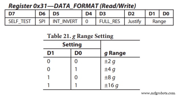
根据应用,我们可以选择合适的灵敏度。在这种情况下,对于跟踪方向,+-2g 灵敏度很好,但对于我们需要从突然运动、冲击等中感知更高加速力的应用,我们可以使用 DATA_FORMAT 寄存器选择其他一些灵敏度范围和它的 D1 和 D0 位。
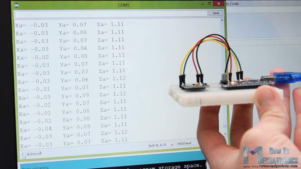
然而,一旦我们读取数据,我们可以简单地将其打印在串行监视器上以检查值是否符合预期。就我而言,我得到的值并不完全符合应有的值,尤其是 Z 轴有 0.1g 的明显误差。
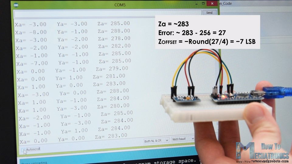
为了解决这个问题,我们需要使用 3 个偏移校准寄存器来校准加速度计,我们可以这样做。因此,我们需要将传感器平放,并打印 RAW 值而不将它们除以 256。
从这里现在我们可以注意到输出关闭了多少,在我的例子中,Z 输出大约是 283。这是正值 27 的差异。现在我们需要将该值除以 4,这将给出我们需要写入 Z 轴偏移寄存器的数字。如果我们现在上传代码,Z轴输出正好是256,应该是1g。
如果需要,我们应该使用相同的方法校准另一个轴。请注意,此校准不会永久写入寄存器。我们需要在传感器每次上电时将这些值写入寄存器。
完成校准后,我们现在终于可以使用这两个公式计算 Roll 和 Pitch,或绕 X 轴的旋转和绕 Y 轴的旋转(以度为单位)。
有关这些公式如何工作的更多详细信息,您可以查看此飞思卡尔半导体应用说明。
好的,现在让我们制作加速度计 3D 可视化示例。
因此,我们使用相同的代码,通过串行端口发送 Roll 和 Pitch 值。这是完整的 Arduino 代码:
现在在处理开发环境中,我们需要接收这些值并使用它们来旋转我们将创建的 3D 对象。这是完整的处理代码:
说明: 所以在这里,我们需要包含串口库,定义串口和波特率,这需要与我们上传的 Arduino 草图的波特率相匹配。然后我们读取传入的数据并将其放入适当的滚动和俯仰变量中。在主绘制循环中,我们使用这些值来旋转 3D 对象,在这种情况下,这是一个简单的盒子,上面有特定的颜色和文本。
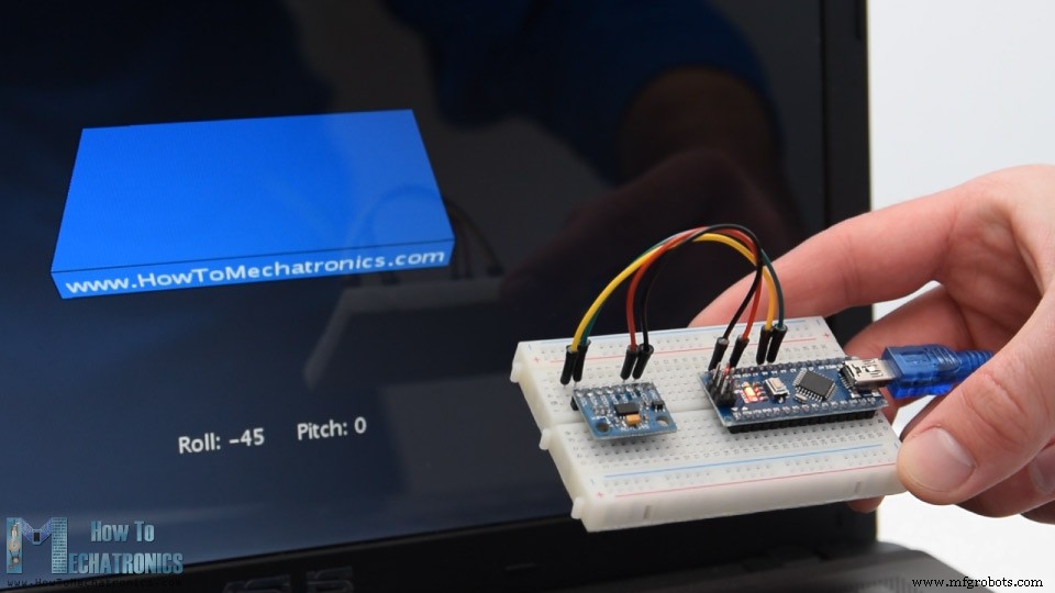
如果我们运行草图,3D 对象将出现,它将跟踪加速度传感器的方向。我们可以注意到,这个物体实际上有点摇晃,这是因为加速度计不仅捕捉到重力,还捕捉到我们手部运动产生的小力。为了得到更平滑的结果,我们可以使用一个简单的低通滤波器。这里我在 Arduino 代码中实现了这样一个过滤器,它占用了之前状态的 94%,并添加了当前状态或角度的 6%。
使用这个过滤器,我们可以注意到对象现在移动得更平滑了,但也有一个副作用,那就是响应速度变慢。我们还可以注意到我们缺少偏航或绕 Z 轴的旋转。仅使用 3 轴加速度计数据我们无法计算 Yaw。
为了做到这一点并提高我们的方向跟踪传感器的整体性能,我们实际上需要包括一个额外的传感器,一个陀螺仪,并将其数据与加速度计融合。
因此,我们既可以将 ADXL345 加速度计与一些陀螺仪传感器结合使用,也可以使用将 3 轴加速度计和 3 轴陀螺仪集成在一个芯片上的 MPU6050 IMU。您可以在我的下一个视频中找到有关此传感器的更详细教程。
我希望你喜欢这个教程并学到了一些新东西。随时在下面的评论部分提出任何问题,不要忘记查看我收集的 Arduino 项目。概览
ADXL345 加速度计的工作原理
如何使用 Arduino 读取 ADXL345 加速度计数据
ADXL345 加速度计 Arduino 代码
/*
    Arduino and ADXL345 Accelerometer Tutorial
     by Dejan, https://howtomechatronics.com
*/

#include <Wire.h>  // Wire library - used for I2C communication

int ADXL345 = 0x53; // The ADXL345 sensor I2C address

float X_out, Y_out, Z_out;  // Outputs

void setup() {
  Serial.begin(9600); // Initiate serial communication for printing the results on the Serial monitor
  Wire.begin(); // Initiate the Wire library
  // Set ADXL345 in measuring mode
  Wire.beginTransmission(ADXL345); // Start communicating with the device
  Wire.write(0x2D); // Access/ talk to POWER_CTL Register - 0x2D
  // Enable measurement
  Wire.write(8); // (8dec -> 0000 1000 binary) Bit D3 High for measuring enable
  Wire.endTransmission();
  delay(10);
}

void loop() {
  // === Read acceleromter data === //
  Wire.beginTransmission(ADXL345);
  Wire.write(0x32); // Start with register 0x32 (ACCEL_XOUT_H)
  Wire.endTransmission(false);
  Wire.requestFrom(ADXL345, 6, true); // Read 6 registers total, each axis value is stored in 2 registers
  X_out = ( Wire.read()| Wire.read() << 8); // X-axis value
  X_out = X_out/256; //For a range of +-2g, we need to divide the raw values by 256, according to the datasheet
  Y_out = ( Wire.read()| Wire.read() << 8); // Y-axis value
  Y_out = Y_out/256;
  Z_out = ( Wire.read()| Wire.read() << 8); // Z-axis value
  Z_out = Z_out/256;

  Serial.print("Xa= ");
  Serial.print(X_out);
  Serial.print("   Ya= ");
  Serial.print(Y_out);
  Serial.print("   Za= ");
  Serial.println(Z_out);
}Code language: Arduino (arduino)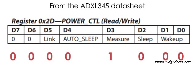
// Set ADXL345 in measuring mode
  Wire.beginTransmission(ADXL345); // Start communicating with the device
  Wire.write(0x2D); // Access/ talk to POWER_CTL Register - 0x2D
  // Enable measurement
  Wire.write(8); // (8dec -> 0000 1000 binary) Bit D3 High for measuring enable
  Wire.endTransmission();Code language: Arduino (arduino)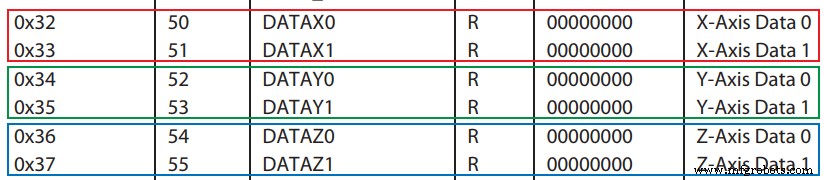
// === Read acceleromter data === //
  Wire.beginTransmission(ADXL345);
  Wire.write(0x32); // Start with register 0x32 (ACCEL_XOUT_H)
  Wire.endTransmission(false);
  Wire.requestFrom(ADXL345, 6, true); // Read 6 registers total, each axis value is stored in 2 registers
  X_out = ( Wire.read()| Wire.read() << 8); // X-axis value
  X_out = X_out/256; //For a range of +-2g, we need to divide the raw values by 256, according to the datasheet
  Y_out = ( Wire.read()| Wire.read() << 8); // Y-axis value
  Y_out = Y_out/256;
  Z_out = ( Wire.read()| Wire.read() << 8); // Z-axis value
  Z_out = Z_out/256;Code language: Arduino (arduino)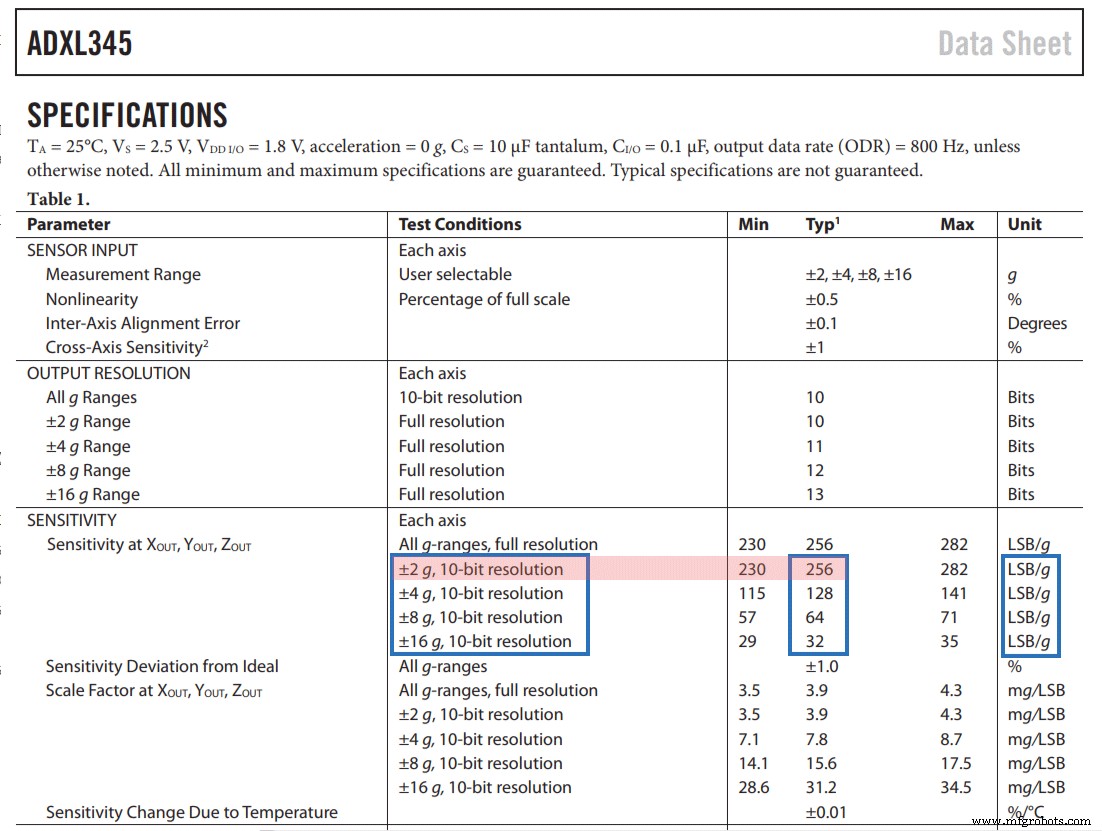
ADXL345 加速度计校准
// This code goes in the SETUP section
// Off-set Calibration
  //X-axis
  Wire.beginTransmission(ADXL345);
  Wire.write(0x1E);  // X-axis offset register
  Wire.write(1);
  Wire.endTransmission();
  delay(10);
  //Y-axis
  Wire.beginTransmission(ADXL345);
  Wire.write(0x1F); // Y-axis offset register
  Wire.write(-2);
  Wire.endTransmission();
  delay(10);

  //Z-axis
  Wire.beginTransmission(ADXL345);
  Wire.write(0x20); // Z-axis offset register
  Wire.write(-7);
  Wire.endTransmission();
delay(10);Code language: Arduino (arduino)// Calculate Roll and Pitch (rotation around X-axis, rotation around Y-axis)
roll = atan(Y_out / sqrt(pow(X_out, 2) + pow(Z_out, 2))) * 180 / PI;
pitch = atan(-1 * X_out / sqrt(pow(Y_out, 2) + pow(Z_out, 2))) * 180 / PI;Code language: Arduino (arduino)Arduino 和 ADXL345 加速度计方向跟踪 - 3D 可视化
/*
    Arduino and ADXL345 Accelerometer - 3D Visualization Example
     by Dejan, https://howtomechatronics.com
*/
#include <Wire.h>  // Wire library - used for I2C communication

int ADXL345 = 0x53; // The ADXL345 sensor I2C address

float X_out, Y_out, Z_out;  // Outputs
float roll,pitch,rollF,pitchF=0;

void setup() {
  Serial.begin(9600); // Initiate serial communication for printing the results on the Serial monitor

  Wire.begin(); // Initiate the Wire library
  // Set ADXL345 in measuring mode
  Wire.beginTransmission(ADXL345); // Start communicating with the device
  Wire.write(0x2D); // Access/ talk to POWER_CTL Register - 0x2D
  // Enable measurement
  Wire.write(8); // Bit D3 High for measuring enable (8dec -> 0000 1000 binary)
  Wire.endTransmission();
  delay(10);

  //Off-set Calibration
  //X-axis
  Wire.beginTransmission(ADXL345);
  Wire.write(0x1E);
  Wire.write(1);
  Wire.endTransmission();
  delay(10);
  //Y-axis
  Wire.beginTransmission(ADXL345);
  Wire.write(0x1F);
  Wire.write(-2);
  Wire.endTransmission();
  delay(10);

  //Z-axis
  Wire.beginTransmission(ADXL345);
  Wire.write(0x20);
  Wire.write(-9);
  Wire.endTransmission();
  delay(10);
}

void loop() {
  // === Read acceleromter data === //
  Wire.beginTransmission(ADXL345);
  Wire.write(0x32); // Start with register 0x32 (ACCEL_XOUT_H)
  Wire.endTransmission(false);
  Wire.requestFrom(ADXL345, 6, true); // Read 6 registers total, each axis value is stored in 2 registers
  X_out = ( Wire.read() | Wire.read() << 8); // X-axis value
  X_out = X_out / 256; //For a range of +-2g, we need to divide the raw values by 256, according to the datasheet
  Y_out = ( Wire.read() | Wire.read() << 8); // Y-axis value
  Y_out = Y_out / 256;
  Z_out = ( Wire.read() | Wire.read() << 8); // Z-axis value
  Z_out = Z_out / 256;

  // Calculate Roll and Pitch (rotation around X-axis, rotation around Y-axis)
  roll = atan(Y_out / sqrt(pow(X_out, 2) + pow(Z_out, 2))) * 180 / PI;
  pitch = atan(-1 * X_out / sqrt(pow(Y_out, 2) + pow(Z_out, 2))) * 180 / PI;

  // Low-pass filter
  rollF = 0.94 * rollF + 0.06 * roll;
  pitchF = 0.94 * pitchF + 0.06 * pitch;

  Serial.print(rollF);
  Serial.print("/");
  Serial.println(pitchF);
}Code language: Arduino (arduino)/*
Arduino and ADXL345 Accelerometer - 3D Visualization Example
by Dejan, https://howtomechatronics.com
*/
import processing.serial.*;
import java.awt.event.KeyEvent;
import java.io.IOException;
Serial myPort;
String data="";
float roll, pitch;
void setup() {
size (960, 640, P3D);
myPort = new Serial(this, "COM8", 9600); // starts the serial communication
myPort.bufferUntil('\n');
}
void draw() {
translate(width/2, height/2, 0);
background(33);
textSize(22);
text("Roll: " + int(roll) + " Pitch: " + int(pitch), -100, 265);
// Rotate the object
rotateX(radians(roll));
rotateZ(radians(-pitch));
// 3D 0bject
textSize(30);
fill(0, 76, 153);
box (386, 40, 200); // Draw box
textSize(25);
fill(255, 255, 255);
text("www.HowToMechatronics.com", -183, 10, 101);
//delay(10);
//println("ypr:\t" + angleX + "\t" + angleY); // Print the values to check whether we are getting proper values
}
// Read data from the Serial Port
void serialEvent (Serial myPort) {
// reads the data from the Serial Port up to the character '.' and puts it into the String variable "data".
data = myPort.readStringUntil('\n');
// if you got any bytes other than the linefeed:
if (data != null) {
data = trim(data);
// split the string at "/"
String items[] = split(data, '/');
if (items.length > 1) {
//--- Roll,Pitch in degrees
roll = float(items[0]);
pitch = float(items[1]);
}
}
}Code language: Arduino (arduino)// Low-pass filter
rollF = 0.94 * rollF + 0.06 * roll;
pitchF = 0.94 * pitchF + 0.06 * pitch;Code language: Arduino (arduino)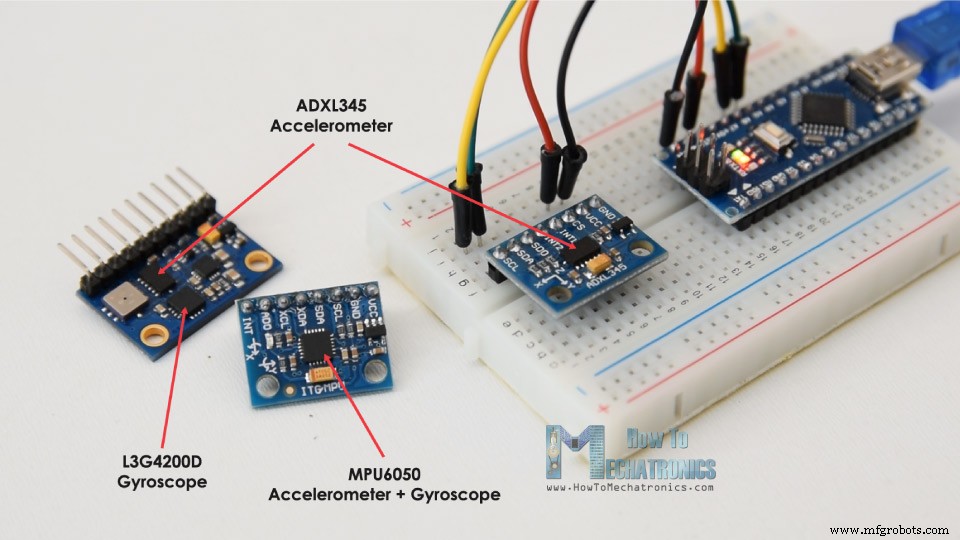
制造工艺
- 使用 Arduino 和 MPU6050 控制伺服电机
- u-blox LEA-6H 02 GPS 模块,带有 Arduino 和 Python
- 如何使用 DHT11 在 Blynk 上读取温度和湿度
- 使用 Arduino 进行语音识别和合成
- 如何用 Arduino 制作音乐
- 如何在 Arduino 中使用 NMEA-0183
- 如何在 Arduino 中使用 Modbus
- 带 Arduino 和蓝牙的智能咖啡机
- 带有 Alexa 和 Arduino 的动画智能灯
- 使用 Arduino 和 BitVoicer 服务器进行语音识别
- 带有 Arduino 和 Python 的人工智能助手机器人
- 使用 Raspberry Pi 和 Arduino 的网络控制 LED 动画