

碳钢和合金钢的锻造
碳钢和合金钢的锻造
碳(C)钢和合金钢的锻造构成了一种金属加工过程,它能够将材料成型为所需的部件形状,同时细化锻造材料的铸造组织,修复缩孔,提高锻件的机械性能。材料。后续加工量也会减少,但这取决于成品零件的几何形状和所使用的锻造工艺。
铸锭一直是锻件的传统起点,可以直接从铸锭锻造,也可以从铸锭热加工的大方坯或钢坯锻造。随着连铸钢的广泛使用,现在通常使用连铸产品作为初始库存。除铸锭、轧制和铸造的大方坯和钢坯外,其他锻件原材料还有板、棒材和铸钢件。
钢铁的锻造始于铁器时代的开始。当时,通过锤击进行的热加工是生产锻铁以及制造锻铁和钢产品的过程的一部分。使用高品位铁矿石、木炭和熔剂的粗熔炉生产少量的铁,这些铁必须手工锻焊在一起才能生产出有用的原料。最初,这是当时锻造的主要目的。人们普遍认为,工业革命的开始是认真地开始锻造钢材。尽管(或者可能是因为)这段悠久的历史,钢的锻造是一个直观的、经验性的过程。
锻件通常以几种方式分类,首先是开模锻造和闭模锻造的一般分类。它们还根据接近完成因素或通过机加工从锻件中去除以满足成品零件的尺寸和细节要求的库存(覆盖)数量进行分类。最后,锻件根据制造所需的锻造设备进一步分类,例如锤式加厚锻件、环轧锻件和多柱压力锻件。在各种分类中,基于接近完成因素的分类与锻件的固有性能(例如强度和抗应力腐蚀)密切相关。一般来说,满足成品零件要求的加工最少的锻件具有最好的性能。
根据 ASTM 规范 A 788,钢锻件是一种实质性压缩塑性加工操作的产品,该操作可巩固材料并产生所需的形状。塑性加工可以通过锤子、压力锻造机或环轧机进行,并且必须使材料变形以产生基本锻造的结构。热轧操作可用于生产用于重锻的大方坯或钢坯。锻件根据锻造温度可分为以下三类。
- 热加工锻件 - 在高于材料再结晶温度的温度下加工生产的锻件。
- 热冷加工锻件 - 锻件在略低于再结晶温度的高温下加工,以提高机械强度。热冷加工锻件可由先前通过锻造或轧制热加工的材料制成。可以在一个连续操作中制造热冷加工锻件,其中材料首先进行热加工,然后通过控制最终温度进行冷加工。由于制造热轧或冷热成品棒材(半成品或成品)的差异,方坯或大方坯不被视为锻件。
- 冷加工锻件 - 在材料发生再结晶的温度范围内通过塑性加工制成的锻件。冷作锻件必须由先前通过锻造或轧制进行热加工的材料制成。
钢材的锻造产品形式包括板、型材、棒材、薄板、带材、管材、管材、挤压件和锻件。通常,挤压件包含在锻件中,但锻件的定义不包括轧制板和棒材。这是因为锻件除了大致符合所需部件的最终形状外,预计不会通过有时与热轧板相关的厚度薄弱或有时与热轧棒材相关的中心不牢固而表现出层状夹杂物的特征。
碳钢和合金钢通常是迄今为止锻造最多的材料,并且很容易使用热锻、温锻或冷锻工艺和标准设备锻造成各种形状。碳钢和合金钢的锻造温度的选择基于碳含量、合金成分、最佳塑性的温度范围以及锻造工件所需的减少量。在这些因素中,碳含量对上限锻造温度的影响最大。
尽管有大量可用的成分,但该类别中的所有材料都显示出基本相似的锻造特性。但含有硫化物等易切削添加剂的钢除外,因为这些材料比非易切削等级更难锻造。通常,碳钢和合金钢的热锻性随着变形率的增加而提高。可加工性的改善主要是由于在高变形率下产生的变形热增加。
选择锻造而不是其他有时更经济的生产有用形状的方法的理由是基于几个考虑因素。锻造材料的机械性能在加工过程中沿主要金属流动的方向最大化。对于复杂的形状,只有锻造提供了引导金属流动与主要应用负载平行的机会,并在一定范围内控制锻造材料原始结构的细化。微观结构的细化是温度、方向和从锻造材料到锻造形状的减小幅度的函数。最大限度地提高材料的结构完整性可以优化设计配置,从而减轻重量。充分控制金属流动以优化复杂锻造配置中的性能通常需要在模锻之前进行一次或多次镦粗操作,并且可能需要空心锻造或反挤压以避免在模具分型线上形成飞边。
由于钢锻件要实现的功能,锻件设计通常包括大的热处理截面尺寸并且可以是不规则的形状,因此可以在所有三个主轴(即(i)纵向)上施加显着的应力,(ii)横向,和(iii)短横向。通过仔细选择原材料尺寸和锻造步骤,锻件有可能在所有三个方向上都显示出良好的性能。在其他情况下,例如,在镦粗盘锻件中,可以在整个圆周的径向方向上实现良好的机械性能,这在从轧制板上简单切割的盘中是可能的。
热锻行为
将碳钢和合金钢热锻成复杂形状的过程很少受到可锻性方面的限制,但易加工等级除外。截面厚度、形状复杂性和锻件尺寸主要受加热工件与冷模具接触时发生的冷却的限制。出于这个原因,模具接触时间相对较短的设备,例如锤子,通常是锻造复杂形状钢的首选。
可伪造性 – 可锻性是钢在压缩载荷下流动而不断裂的相对能力。除再硫和再磷钢外,大多数碳钢和低合金钢通常被认为具有良好的可锻性。不同等级钢之间的锻造行为差异很小,很少会通过锻造行为影响钢材的选择。然而,锻件选择加硫或再磷化钢通常只有在锻件要进行广泛加工时才合理,因为考虑通过锻造生产的主要原因之一是避免后续加工操作,这种情况并不常见。
测量钢的可锻性的一种常用方法是热扭试验。顾名思义,该测试涉及在选择覆盖测试材料可能的热工作温度范围的多个不同温度下扭曲加热棒样品以使其断裂。报告了扭转断裂的次数,以及保持扭转以恒定速率所需的扭矩。捻数最大的温度(如果存在这样的最大值)被假定为测试材料的最佳热加工温度。几种碳钢通过热扭试验确定的可锻性如图1所示。下面给出的各种其他试验用于评估钢的可锻性。
- 楔形锻造试验 - 在该试验中,在平模之间锻造一个楔形试样,并确定导致开裂的垂直变形。
- 侧压测试 - 该测试包括在平行的扁平模具之间压缩圆柱棒样品,使圆柱轴平行于模具。圆柱体端部不受约束,可锻性通过开裂前获得的变形量来衡量。
- 加厚测试 - 在此测试中,圆柱体在平面模具之间被压缩,并测量圆柱体赤道断裂处的表面应变。
- 缺口棒加厚测试 - 该测试与加厚测试类似,只是在测试样品中加工了轴向缺口以引入较高的局部应力水平。与标准加厚测试中产生的应力相比,这些更高的应力更能说明实际锻造操作中所经历的应力。
- 热拉伸测试 - 该测试经常使用特殊的测试设备在很宽的范围内改变应变率和温度。
应变率对可锻性的影响 – 钢的可锻性通常随着应变率的增加而增加。这种效应已在低碳钢的热扭曲测试中得到证实(图 1),其中扭曲失效的次数随着扭曲率的增加而增加。人们认为,在较高应变率下可锻性的这种改进是由于在较高应变率下产生的变形热增加。然而,变形热导致温度升高过快,会导致初熔,从而降低可锻性和力学性能。
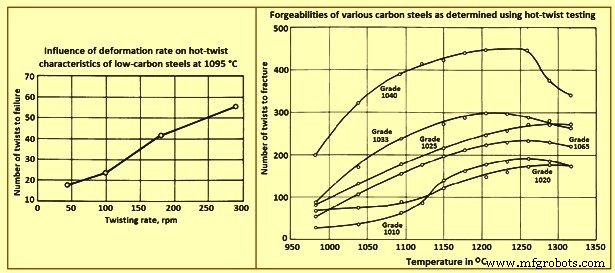
图1 各种碳钢变形率和可锻性的影响
流变应力和锻压 – 流动应力和锻造压力可以从热扭曲测试或热压缩或拉伸测试中产生的扭矩曲线中获得。这些曲线的数据表明,这组合金的相对锻压要求在正常热锻温度下变化不大。合金化程度更高的材料需要相当大的压力,而且这种合金材料的锻造压力也随着压下量的增加而增加更显着。
应变率对锻压的影响 – 给定钢材所需的锻造压力随着应变率的增加而增加。对低碳钢的研究表明,在较高的锻造温度下,应变率的影响更为明显。这种影响如图 2 所示,它给出了在不同温度和应变率下锻造的低碳钢的应力-应变曲线。在合金钢中也观察到了类似的效果。
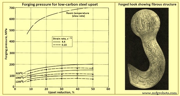
图 2 不同温度和两种应变率下低碳钢镦粗的锻造压力
锻造用钢的选择
用于锻造的碳钢和合金钢锭、大方坯、钢坯和板坯是热轧或铸造成近似横截面尺寸的,因此,直线度、弯曲度、扭曲度和平面度公差不适用。锻造用钢半成品按规定的单件重量或规定的长度生产。
表面处理 – 用于锻造的半成品钢产品可以通过刮削、切削或研磨来去除或最小化表面缺陷。但需要注意的是,无论表面处理如何,产品仍有可能存在一些表面缺陷。
重量公差 – 对于单件或重量小于 18 吨的批次,方坯、大方坯和板坯的公差通常为 +/- 5 %。超过此重量的批次通常会受到 +/- 2.5 % 的重量公差。
切割 – 用于锻造的半成品钢材通常通过热剪切定尺切割。根据钢的成分,也可以使用热锯或火焰切割。
质量 – 用于锻造的半成品钢产品的质量取决于许多不同的因素,包括内部健全程度、化学成分的相对均匀性以及表面缺陷的相对自由度。
锻造质量半成品钢用于热锻应用,可能涉及后续热处理或机加工操作。此类应用需要对化学成分和钢铁生产进行相对严格的控制。
为锻造部件选择钢材是设计过程的一个组成部分,可接受的性能取决于这种选择。仔细了解成品零件的最终用途有助于确定所需的机械性能、表面光洁度要求、对非金属夹杂物的耐受性以及随之而来的检验方法和标准。
锻造质量钢的化学成分范围很广。对于每一种熔化和轧制实践,都会进行一定程度的质量测试和评估。如果有必要,可以对钢规定一个或多个特殊的质量限制,例如非金属夹杂物的出现水平。有时,为了获得更高的可靠性应用,需要对钢进行真空电弧重熔或电渣重熔工艺。
近年来,微合金钢的使用有所发展,例如汽车曲轴。这些钢通常含有少量(0.05% 至 0.1%)钒或铌,并且在非热处理(如锻造)条件下可以获得可接受的性能。因此,这些合金保留了锻造工艺的优势,同时由于取消了热处理循环,在经济上与铸件相比具有竞争力。
设计要求 – 锻造零件的钢材选择通常需要在相反的因素之间进行某种折衷,例如强度与韧性、抗应力腐蚀与重量、制造成本与有效承载能力、生产成本与维护成本以及制造成本钢材原材料与锻件的总制造成本。材料选择还涉及到熔化实践、成型方法、机加工操作、热处理程序、性能随使用时间的劣化以及待锻钢的常规机械和化学性能的考虑。
高效的锻造设计可通过与要施加的载荷、可生产性和预期寿命一致的最少材料量实现最大性能。为了使钢材与其设计部件相匹配,首先要对钢材进行强度和韧性评估,然后对温度和环境的稳定性进行鉴定。然后分析最佳钢材的生产性和经济性。
失效分析是一种有用的数据源,用于将钢的特性与要求相匹配。在设计应力范围内的运行过程中,可能会发生组件故障。过早失效的一个原因是关键设计应力没有与锻件的优选晶粒流动进行适当的定向。由于性能随时间和服务而恶化,也可能发生意外故障。例如,由持续拉伸应力引起的应力腐蚀开裂即使在典型的环境气氛中也可能发生。在这些条件下,最有可能在锻件中与暴露的末端晶粒重合的位置发生故障。失效分析可以发现过早失效的其他原因,例如晶粒过度生长、非金属杂质夹杂、因锻造不当造成的晶粒流动折叠、缺乏锻造金相结构,以及因加工过度而无意中产生的应力增加。锋利的圆角或装配不当。
锻造对性能的影响
从碳钢或合金钢棒或钢坯成型复杂配置首先需要将钢“排列”成合适的起始形状(预成型),然后使其流入最终零件配置。金属的这种重新排列对钢的硬度和强度影响不大,但某些机械性能(如延展性、冲击强度和疲劳强度)得到了增强。性能的这种改进(图 2)是因为锻造 (i) 打破了偏析,修复了孔隙率,并有助于均匀化,(ii) 产生了纤维状晶粒结构,从而增强了与晶粒流动平行的机械性能,以及 (iii) 降低了-铸件粒度。
图 3 显示了热处理钢的延展性和冲击强度随锻造压下率的典型改善。这些数据表明,在每种情况下,最大的改善发生在最大伸长率的方向上。一定量的压下后韧性和延展性达到最大值,再压下价值不大。
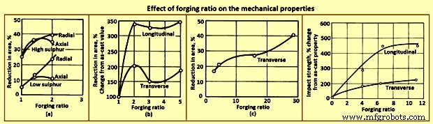
图3锻造比对力学性能的影响
表 1 给出了低碳和中碳钢锻件在退火、正火和调质条件下的典型纵向力学性能。正如可以预期的那样,强度随着碳含量的增加而增加,而延展性降低。应该认识到,大部分闭模锻件是由经过大量预先加工的锻坯制成的。然而,自由锻件可以由锻造坯料或铸态产品制成。
| Tab 1 碳钢锻件在四种碳含量下的纵向性能 | |||||||
| Sl. No. | 碳含量 | 极限抗拉强度 | 屈服强度,0.2 % 偏移 | 伸长率 | 面积缩小 | 疲劳强度 * | 硬度 |
| % | 兆帕 | MPa | % | % | 兆帕 | HB | |
| 退火 | |||||||
| 1 | 0.24 | 438 | 201 | 39 | 59 | 185 | 122 |
| 2 | 0.30 | 483 | 245 | 31.5 | 58 | 193 | 134 |
| 3 | 0.35 | 555 | 279 | 24.5 | 39 | 224 | 157 |
| 4 | 0.40 | 634 | 348 | 24 | 42 | 248 | 180 |
| 标准化 | |||||||
| 1 | 0.24 | 483 | 247 | 34 | 56.5 | 193 | 134 |
| 2 | 0.30 | 521 | 276 | 28 | 44 | 209 | 148 |
| 3 | 0.35 | 579 | 303 | 23 | 36 | 232 | 164 |
| 4 | 0.40 | 690 | 355 | 22 | 36 | 255 | 196 |
| 595℃油淬回火 | |||||||
| 1 | 0.24 | 500 | 305 | 35.5 | 62 | 193 | 144 |
| 2 | 0.30 | 552 | 301 | 27 | 52 | 224 | 157 |
| 3 | 0.35 | 669 | 414 | 26.5 | 49 | 247 | 190 |
| 4 | 0.40 | 724 | 386 | 19 | 31 | 277 | 206 |
| * 10,000,000 耐久极限下的旋转光束测试 | |||||||
金属在闭模锻造过程中沿不同方向流动。例如,在诸如空气框架部件的肋和腹板形状的锻造中,几乎所有的金属流动都是在横向方向上。这种横向流动提高了该方向的延展性,而纵向延展性几乎没有降低。如果锻造减少量足够大并且金属流动主要是在横向上,则横向延展性可以想象到等于或超过纵向延展性。在锻造坯料的镦粗中也观察到了类似的效果。然而,在这种情况下,材料的原始纵轴因镦粗而缩短,金属的横向位移为径向。当镦粗减少量超过 50% 左右时,径向的延展性通常超过轴向(图 4)。
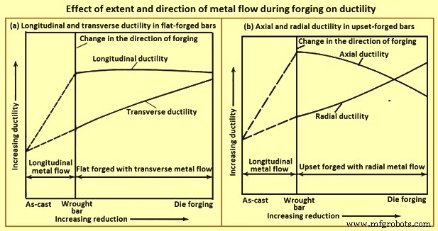
图 4 加厚减少对锻钢轴向和径向延展性的典型影响
锻造结构和延展性 – 材料控制的另一个方面确保最终锻件已经经历了足够的塑性变形,以达到开发设计所基于的机械性能所必需的锻造结构。尽管在铸造产品分解为锻造坯料期间会实现一些塑性变形,但在闭模锻造过程中会产生更多的塑性变形。高强度锻件的材料控制需要确定锻坯的力学性能以及锻件的力学性能。
延展性或韧性的量度是通过测量横向拉伸测试样品中获得的面积减少量来确定的。当对热处理到相同强度水平的锻件的横向和纵向试样进行相应的测试时,可以比较坯料和锻件的力学性能,并估计各自贡献的最终锻造金相组织的比例。
延展性与锻减量 – 材料控制的一个主要目标是确保在成品锻件中实现最佳机械性能。如图 4 所示,锻造过程中实现的减少量对延展性有显着影响,该图比较了铸锭、锻造(轧制)棒材或钢坯以及锻件的延展性。图 4(a) 中的曲线表明,当锻棒或钢坯在模具中平锻时,锻造减量的增加不会影响纵向延展性,但会导致横向延展性逐渐增加。当类似的棒材或钢坯在模具中镦粗锻造时,锻造减量的增加导致轴向延展性逐渐降低,径向延展性逐渐增加。
铸锭的延展性随化学成分、熔炼方法和铸锭尺寸而变化。相同合金成分的钢锭的延展性也有所不同,这取决于它们是由空气熔炼钢还是真空电弧重熔钢浇注而成。当从特定合金的大锭开始时,有时将锭的一部分轧制成各种钢坯或棒材尺寸并具有不同的锻造减少量。最小减量没有标准,但很少低于2:1(钢锭截面积与钢坯截面积之比)。钢锭与钢坯的还原比通常远大于 2:1。相比之下,一些耐热合金锻件是直接由铸锭锻造而成的。
通常,为大到需要锭的整个重量的锻件准备坯料是不可行的。以锻造冶金结构为代表的锻造减少量最好通过观察和测试从完成的锻件中取出的宏观蚀刻和拉伸测试样品来控制。这些样品允许探索关键区域,通常是整个锻件。它们根据需要从纵向、长横向和短横向晶粒方向中选择。蚀刻测试允许目视观察晶粒流动。机械测试将强度和韧性与晶粒流动相关联。
粮食流动 – 宏观蚀刻允许直接观察晶粒方向和轮廓,也可用于检测折叠、重叠和重入流。通过对合适的样品进行宏观蚀刻,可以在纵向、长横向和短横向方向上检查晶粒流动。宏观蚀刻还允许评估完整的部分,端到端和边到边,并审查宏观晶粒尺寸的均匀性。图2为代表性锻件的晶粒流动。
粒度和微量成分 – 金相检验,使用显微镜,最适合检查宏观蚀刻揭示的可疑区域,测量晶粒尺寸,确定微量成分的性质和数量。
疲劳强度 – 疲劳测试用于材料控制的条件和目的,例如 (i) 用于材料开发或鉴定的小样品的实验室测试,(ii) 用于设计开发的完整组件或子组件的实验室测试,以及(iii) 现场监控组件或组件,以确保其在服务中的持续可靠性。
用于材料鉴定或开发的小样品的实验室疲劳测试是通过标准方法进行的。根据需要,测试样品取自轧机产品或闭模锻件。标准样品足够小,可以从锻件内的许多位置进行选择,并与晶粒流动的各个方向相关联。测试通常在室温下在空气中进行,但在更高或更低温度和特殊气氛中测试也是可行的。
将小规模实验室疲劳测试应用于部件或组件的分析会引入额外的变量。一是表面条件的影响。图 5(a) 中的曲线表明,钢样品的疲劳强度显着变化,这取决于表面是抛光、机加工、热轧还是锻造。所测试的钢是一种锻造低合金钢,热处理到 269 HB 到 285 HB,相当于 876 MPa 的抗拉强度和 696 MPa 的屈服强度。样品制备需要在热处理后对样品进行机加工和抛光,并且在热处理之前进行轧制或锻造。对于 106 次循环的疲劳寿命,磨制样品的疲劳极限为 395 MPa,机加工样品为 315 MPa,轧制样品为 205 MPa,锻造样品仅为 150 MPa。
图 5(b) 中的曲线适用于抗拉强度范围为 345 MPa 至 2,070 MPa 的钢,是几个试验的近似值。 965 MPa 拉伸强度水平的锻造或脱碳样品的样品制备包括从棒料粗加工的钢,在燃气马弗炉中加热到 900 摄氏度左右 20 分钟到 30 分钟,从原始的非常轻微的型锻直径 7.47 毫米至最终直径 7.16 毫米,空气冷却。热处理包括在约 830 摄氏度的盐浴中奥氏体化 45 分钟,油淬,在约 620 摄氏度的空气中回火 1 小时,以及水淬。锻造和热处理产生的表面脱碳深度约为 0.064 毫米。这些样品在 106 次循环时显示出约 310 MPa 的疲劳强度,而未经锻造但经过机加工或抛光且无脱碳的样品的疲劳强度为 470 MPa。脱碳降低了通过热处理获得的强度水平。在锻造部件的批量生产中,表面状况的实验室控制难以复制。因此,由于表面条件的变化,全尺寸部件的疲劳强度比小样品的疲劳强度变化范围更广。
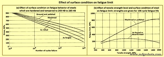
图5表面状态对疲劳极限的影响
断裂韧性 – 锻件和其他部件的脆性断裂是裂纹在远低于钢材屈服强度的应力水平下扩展的结果,这导致了对断裂特征和断裂韧性评估方法的广泛研究。这些研究的结果对于材料控制非常重要,特别是在开发用于评估断裂韧性的测试方面,这些测试可以作为材料控制标准的依据。
在实验室测试和分析技术领域,主要重点是开发可靠的方法来评估包含裂纹或裂纹状缺陷的钢的强度。具体来说,兴趣集中在确定平面应变断裂韧性的方法上。通过测试从锻件上选定位置取出的代表不同晶粒方向的小样本来评估锻造部件。
一种测试程序包括在中性环境中对缺口和疲劳裂纹样品进行弯曲测试。 The objective of this test is to get a lower limiting value of fracture toughness which can be used to estimate the relationship between stress and defect size in a metal under service conditions in which high constraint is expected. In the test procedure referred to, a test sample with a chevron notch is suitably pre-cracked in fatigue. It is then tested in a bend test fixture provided with support rolls which rotate and move apart slightly to permit rolling contact and virtually eliminate the friction effect. The sample is subjected to three-point bending, and the imposed load versus displacement change across the notch is recorded on an autographic recorder. Fracture toughness is rated by a calculated parameter, the critical stress intensity.
End-grain exposure – Lowered resistance to stress-corrosion cracking in the long-transverse and short-transverse directions is related to the end-grain exposure. A long, narrow test sample sectioned so that the grain is parallel to the longitudinal axis of the sample has no exposed end grain, except at the extreme ends, which are not subjected to the loading. In contrast, a corresponding sample cut in the transverse direction has end-grain exposure at all points along its length. End grain is especially pronounced in the short-transverse direction on die forgings designed with a flash line. Consequently, forged components designed to reduce or eliminate end grain have better resistance to stress-corrosion cracking.
Residual stress – The sustained tensile stress at the surface of a forging which contributes to stress-corrosion cracking is the total of applied and residual stresses. When the residual stress constitutes a significant percentage of the total stress, it is to be reduced or eliminated. Common sources of residual tensile stresses include quenching, machining, and poor fit in assembly. Each can be suitably modified to reduce or eliminate tensile stresses, especially those present in an exposed surface. As an example, drastic quenching places the surface of a heat-treatable alloy in a state of compression and the core in a state of tension. Furthermore, the compressed surface can be entirely removed during rough machining, exposing the tension-stressed core material. This hazard can be avoided by quenching after, rather than before, rough machining. In some applications, a surface in tension is placed in compression by shot peening.
Hydrogen-stress cracking occurs without corrosion. Hence, its initiation is not confined to exterior surfaces in contact with a corrosive medium. It can start at any suitable nucleus, such as an inclusion or void, as well as at a surface notch or other irregularity. Hydrogen-stress cracking at the interior is described as hydrogen embrittlement or hydrogen flaking. Hydrogen-stress cracking has been observed, studied, and brought under control in most high-strength steels. The modern practice of vacuum melting can reduce residual hydrogen to negligible amounts. A hydrogen content of 3 ppm to 6 ppm in air-melted steel can be readily lowered to 0.6 ppm to 1 ppm by vacuum arc remelting. Provided that the initial hydrogen content of the steel is acceptably low, material control procedures are to ensure that hydrogen pickup is avoided in all subsequent processing, including forging, heat treating, hot salt bath descaling, pickling, and plating. During forging, steels develop a surface scale and a decarburized surface layer, both of which are subsequently removed by grit blasting and machining. Unless the steel is acid pickled, there is no possibility of hydrogen pickup.
Many of the critical parts made from steel forgings are protected by a coating of cadmium. Steel parts heat treated to strength levels higher than 1,655 MPa are especially sensitive to hydrogen pickup, in case they are coated with cadmium, the coating is deposited in vacuum. Parts heat treated to strength levels lower than 1,655 MPa can be cadmium plated electrolytically, provided that a titanium-containing plating bath is used and the parts are subsequently baked at around 190 deg C for 12 hours.
Mechanical properties – A major advantage of shaping metal parts by rolling, forging, or extrusion stems from the opportunities such processes offer the designer with respect to the control of grain flow. The strength of these and similar wrought products is almost always greatest in the longitudinal direction (or equivalent) of grain flow, and the maximum load-carrying ability in the finished part is achieved by providing a grain-flow pattern parallel to the direction of the major applied service loads when, in addition, sound, dense, good-quality metal of sufficiently fine grain size has been produced throughout.
Grain flow and anisotropy – Steel which is rolled, forged, or extruded develops and retains a fiber like grain structure aligned in the principal direction of working. This characteristic becomes visible on external and sectional surfaces of wrought products when the surfaces are suitably prepared and etched. The fibers are the result of elongation of the micro-structural constituents of the steel in the direction of working. Hence, the phrase ‘direction of grain flow’ is normally used to describe the dominant direction of these fibers within wrought metal products.
In wrought steel, the direction of grain flow is also evidenced by measurements of mechanical properties. Strength and ductility are almost always greater in the direction parallel to that of working. The characteristic of showing different strength and ductility values with respect to the direction of working is referred to as mechanical anisotropy and is exploited in the design of wrought products. Although the best properties in wrought steels are most frequently the longitudinal (or equivalent), properties in other directions can yet be superior to those in products not wrought, that is, in cast ingots or in forging stock taken from a lightly worked ingot.
Rectangular sections show anisotropy among all the three principal directions i.e. longitudinal, long transverse, and short transverse. A design which employs a rectangular section involves the properties in all these directions, not just the longitudinal. Hence, the longitudinal, long-transverse, and short-transverse service loads of rectangular sections are analyzed separately.
Anisotropy in high strength steel – Although all wrought steels are mechanically anisotropic, the effects of anisotropy on mechanical properties vary among different metals and alloys. For example, a vacuum-melted steel of a given composition is generally less mechanically anisotropic than a conventionally killed, air-melted steel of the same composition. Response to etching to reveal the grain flow characteristic of anisotropy also varies. Steels with poor corrosion resistance are readily etched, while those with good corrosion resistance need more corrosive etchants and extended etching times to reveal grain flow. In general, fatigue properties are markedly affected by the relation of flow-line direction to direction of stresses from applied loads. When flow lines are perpendicular to load stresses, a stress-raising effect is produced.
Forging lubricants
For many years, oil-graphite mixtures have normally being used as lubricants for forging carbon and alloy steels. Recent advances in lubricant technology, however, have resulted in new types of lubricants, including water/graphite mixtures and water-base synthetic lubricants. Each of the normally used lubricants has advantages as well as limitations (Tab 2) which is required to be balanced against process requirements.
| Tab 2 Advantages and limitations of the main lubricants used for hot forging of steels | |||
| Sl. No. | Type of lubricant | Advantages | Limitations |
| 1 | Water-base micro-graphite | Eliminates smoke and fire; provides die cooling; is easily extended with water | Must be applied by spraying for best results |
| 2 | Water-base synthetic | Eliminates smoke and fire; is cleaner than oils or water-base graphite; aids die cooling; is easily diluted, and needs no agitation after initial mixing; reduces clogging of spray equipment; does not transfer dark pigment to part | Must be sprayed; lacks the lubricity of graphite for severe forging operations |
| 3 | Oil-base graphite | Fluid film lends itself to either spray or swab application; has good performance over a wide temperature range (upto 540 deg C). | Generates smoke, fire, and noxious odours; explosive nature may shorten die life; has potentially serious health and safety implications for workers |
Selection criteria – Lubricant selection for forging is based on several factors, including forging temperature, die temperature, forging equipment, method of lubricant application, complexity of the part being forged and environmental and safety considerations. At normal hot-forging temperatures for carbon and alloy steels, water-base graphite lubricants are used almost exclusively, although some hammer shops still employ oil-base graphite.
The most common warm-forming temperature range for carbon and alloy steels is 540 deg C to 870 deg C. Because of the severity of forging conditions at these temperatures, billet coatings are often used in conjunction with die lubricants. The billet coatings used include graphite in a fluid carrier or water-base coatings used in conjunction with phosphate conversion coating of the work piece. For still lower forging temperatures (less than around 400 deg C, molybdenum disulphide has a greater load-carrying capacity than does graphite. Molybdenum disulphide can either be applied in solid form or dispersed in a fluid carrier.
Heat treatment of carbon and alloy steel forgings
Normally steel forgings are specified based upon one of four man conditions namely (i) as forged with no further thermal processing, (ii) heat treated for machinability, (iii) heat treated for final mechanical / physical properties, or (iv) special heat treatment to enhance dimensional stability, particularly in more complex part configurations.
As forged with no further thermal processing – Although the vast majority of steel forgings are heat treated before use, a large tonnage of low carbon steel (0.1 % to 0.25 % C) is used in the as-forged condition. In such forgings, machinability is good, and little is gained in terms of strength by heat treatment. In fact, a number of widely used specifications permit this economic option. It is also interesting to note that, compared to the properties produced by normalizing, strength and machinability are slightly better, which is most likely attributable to the fact that grain size is somewhat coarser than in the normalized condition.
Heat treated for machinability – When a finished machined component is to be produced from a roughly dimensioned forging, machinability becomes a vital consideration to optimize tool life, increase productivity, or both. The specification or forging drawing can specify the heat treatment. However, when specifications give only maximum hardness or micro-structural specifications, the most economical and effective thermal cycle is to be selected. Available heat treatments include full anneal, spheroidize anneal, sub-critical anneal, normalize, or normalize and temper. The heat treatment chosen depends on the steel composition and the machine operations to be performed. Some steel grades are inherently soft while others become quite hard in cooling from the finishing temperature after hot forging. Some type of annealing is usually required or specified to improve machinability.
Heat treated for final mechanical / physical properties – Normalizing or normalizing and tempering can produce the needed minimum hardness and minimum ultimate tensile strength. However, for most steels, a hardening (austenitize) and quenching (in oil, water, or some other medium, depending on section size and hardenability) cycle is employed, followed by tempering to produce the proper hardness, strength, ductility, and impact properties. For steel forgings to be heat treated above the 1,035 MPa strength level and having section size variations, it is general practice to normalize before austenitizing to produce a uniform grain size and minimize internal residual stresses. In some instances, it is normal practice to use the heat for forging as the austenitizing cycle and to quench at the forge unit. The forging is then tempered to complete the heat treat cycle. Although there are obvious limitations to this procedure, definite economies are possible when the procedure is applicable (usually for symmetrical shapes of carbon steels which need little final machining).
Special heat treatment to enhance dimensional stability – Special heat treatments, particularly in more complex part configurations, are sometimes used to control dimensional distortion, relieve residual stresses before or after machining operations, avoid quench cracking, or prevent thermal shock or surface (case) hardening. Although most of the heat-treating cycles can apply, very specific treatments can be needed. Such treatments normally apply to complex forging configurations with adjacent differences in section thickness, or to very high hardenability steels and alloys. When stability of critically dimensioned finished parts permits only light machining of the forging after heat treatment to final properties, special treatments are available, including mar-quenching (mar-tempering), stress relieving, and multiple tempering.
Many applications, such as crankshafts, camshafts, gears, forged rolls, rings, certain bearings, and other machinery components, need increased surface hardness for wear resistance. The important surfaces are normally hardened after machining by flame or induction hardening, carburizing, carbo-nitriding, or nitriding. These processes are listed in the approximate order of increasing cost and decreasing maximum temperature. The latter consideration is important in that dimensional distortion normally decreases with decreasing temperature. This is particularly true of nitriding, which is usually performed below the tempering temperature for the steel used in the forging.
Micro-alloyed forging steels
Micro-alloying (the use of small amounts of elements such as vanadium and niobium to strengthen steels) has been in practice since the 1960s to control the micro-structure and properties of low carbon steels. Most of the early developments have been related to plate and sheet products in which micro-alloy precipitation, controlled rolling, and modern steelmaking technology combined to increase strength significantly relative to that of low carbon steels.
The application of micro-alloying technology to forging steels has lagged behind that of flat-rolled products because of the different property requirements and thermo-mechanical processing of forging steels. Forging steels are normally used in applications in which high strength, fatigue resistance, and wear resistance are needed. These requirements are most often filled by medium carbon steels. Thus, the development of micro-alloyed forging steels has been based around the grades containing 0.3 % to 0.5 % C.
The driving force behind the development of micro-alloyed forging steels has been the need to reduce the production costs. This is accomplished in these materials by means of a simplified thermo-mechanical treatment (that is, a controlled cooling following hot forging) which achieves the desired properties without the separate quenching and tempering treatments required by conventional carbon and alloy steels. In Fig 6, the processing sequence for conventional (quenched and tempered) steels is compared with the micro-alloyed steel-forging process.
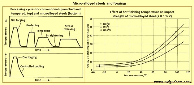
Fig 6 Micro-alloyed steels and forgings
Effects of micro-alloying elements
Carbon – Most of the micro-alloyed steels developed for forging have carbon contents ranging from 0.3 % to 0.5 %, which is high enough to form a large amount of pearlite. The pearlite is responsible for substantial strengthening. This level of carbon also decreases the solubility of the micro-alloying constituents in austenite.
Niobium, vanadium, and titanium – Formation of carbo-nitride precipitates is the other major strengthening mechanism of micro-alloyed forging steels. Vanadium, in amounts ranging from 0.05 % to 0.2 %, is the most common micro-alloying addition used in forging steels. Niobium and titanium enhance strength and toughness by providing control of austenite grain size. Frequently niobium is used in combination with vanadium to achieve the benefits of austenite grain size control (from niobium) and carbo-nitride precipitation (from vanadium).
Manganese – Manganese is used in relatively large amounts (1.4 % to 1.5 %) in many micro-alloyed forging steels. It tends to reduce the cementite plate thickness while maintaining the inter-lamellar spacing of pearlite developed. Hence, high manganese levels require lower carbon contents to retain the large amounts of pearlite required for high hardness. Manganese also provides substantial solid solution strengthening, enhances the solubility of vanadium carbonitrides, and lowers the solvus temperature for these phases.
Silicon – The silicon content of most commercial micro-alloyed forging steels is around 0.3 %. Some grades contain upto 0.7 %. Higher silicon contents are associated with significantly higher toughness, apparently because of an increased amount of ferrite relative to that formed in ferrite-pearlite steels with lower silicon contents.
Sulphur – Many micro-alloyed forging steels, particularly those needed for use in automotive forgings in which machinability is critical, have relatively high sulphur contents. The higher sulphur contents contribute to their machinability, which is comparable to that of quenched and tempered steels.
Aluminum and nitrogen – As in hardenable fine-grain steels, aluminum is important for austenite grain size control in micro-alloyed steels. The mechanism of aluminum grain size control is the formation of aluminum nitride particles. It has been shown that nitrogen is the major interstitial component of vanadium carbo-nitride. For this reason, moderate to high nitrogen contents are needed in vanadium containing micro-alloyed steels to promote effective precipitate strengthening.
Controlled Forging
The concept of grain size control has been used for many years in the production of flat rolled products. Particularly in plate rolling, the ability to increase austenite recrystallization temperature using small niobium additions is well known. The process used to produce these steels is usually referred to as controlled rolling. The benefits of austenite grain size control are not, of course, limited to flat rolled products. Although the higher finishing temperatures needed for rolling of bars limit the usefulness of this approach to micro-structural control, finishing temperatures for micro-alloyed bar steels is nonetheless to be controlled.
It has been shown that, although strength is not significantly affected by finishing temperature, toughness of vanadium-containing micro-alloyed steels decreases with increasing finishing temperature. This effect is shown in Fig 6, which compares Charpy V-notch impact strength for a micro-alloyed steel finished at three temperatures. This detrimental effect of a high finishing temperature on impact toughness also carries over to forging operations, that is, the lower the finish temperature in forging, the higher the resulting toughness, and vice versa. After extensive testing, it has been shown that the finishing temperature for forging if reduced to near 1000 deg C, results in impact properties equal to or better than those of hot rolled bar. It is also shown that rapid induction preheating is beneficial for micro-alloyed forging steels, and that cost savings of 10 % (for standard micro-alloyed forgings) to 20 % (for resulphurized grades) are possible.
Lower finishing temperatures, however, take their toll in terms of higher required forging pressures (and thus higher machine capacities needed) and increased die wear. The improved toughness resulting from lower finishing temperatures, as well as any cost savings which can be achieved as a result of the elimination of heat treatment, is to be weighed against the cost increases caused by these factors.
Micro-alloyed cold heading steels -Steels used in the production of high-strength fasteners by cold heading have been earlier produced from quenched and tempered alloy steels. To obtain sufficient strength with adequate ductility needed six processing steps. Recent developments have led to the use of micro-alloyed niobium-boron steels which need no heat treatment. These steels make use of niobium and boron additions to develop bainitic structures with high work-hardening rates. In most cases they use the deformation of cold heading to achieve the required strength levels without heat treatment.
制造工艺