

烟气净化技术和系统
烟气净化技术和系统
环境污染是目前全世界面临的最大问题之一。从一系列全球性的环境问题中,现在越来越多的人认识到环境和资源是人类生存和发展的基本必需品。作为大多数技术过程的产物的烟气被各种固体颗粒污染。为了进一步使用气体(如果它们具有足够的热值)或将它们释放到大气中,有必要对气体进行清洁。然而,大气排放控制需要花钱,很少有任何财务回报给运营组织。
过去几年,各国在排放控制领域的态度、教育、责任和法规发生了彻底的变化。随着时间的推移,排放控制法规变得越来越严格,以试图拯救子孙后代免受大气污染的不良影响。现在,一些组织正在迅速改变他们对大气污染的态度,并积极参与污染控制活动。现在,组织希望被公众视为生产“清洁”产品的负责任的组织。这部分是市场驱动的,因为市场现在需要越来越多的“清洁”产品。在当今情况下,客户在对环境的责任以及拥有清洁环境的好处方面都受到了更多的教育。
烟气净化系统的目的是减少对环境和健康有害的物质的大气排放。这包括例如重金属、二恶英和引起酸化和富营养化的物质。由于烟气中的某些物质具有毒性和致癌性,因此减少其排放非常重要。通过去除烟气中的硫氧化物和氮氧化物,大大减少了森林和湖泊的酸化。
冶金、化工和热电厂的工艺流程会产生通常充满灰尘和高温的废气。这些气体的成分和数量取决于工艺流程和原材料的性质。废气的排放实际上是使用的原材料以及这些工厂中发生的过程和反应的结果。烟道气可能含有二氧化碳、一氧化碳、硫氧化物(SO2 和 SO3)和氮氧化物 (NOx)、氢气、硫化氢 (H2S)、氟(HF 形式)、氯气(HCl 形式) )、砷、汞、挥发性有机化合物 (VOC)、水蒸气和灰尘等。水蒸气是无害的,但会在烟囱出口处形成可见的烟羽。
有几种技术过程在高温下进行。此外,许多这些工艺处理原材料,其中一些是细粉形式。因此,所有这些过程都容易将污染气体和颗粒物排放到大气中。这反过来又会影响工厂周围的空气质量。为了改善和保护空气质量,使用不同的污染控制装置来减少排放。多年来,污染控制设备仅用于那些污染物含量非常高或具有毒性的过程。这些设备也较早用于具有一定回收价值的地方。但在目前的情况下,随着环境法规越来越严格,社会对环境的关注度越来越高,有必要对所有工艺流程的排放进行调查,并在各个领域安装设备以减少将排放降至最低水平。
通常归因于技术过程的大气污染源至少有五组,每组都有特定的最佳减排技术。由于遇到强酸性气体浓度,这些分组不构成完整列表;将实施替代烟气净化技术,例如硫酸厂。气体净化技术的这五个主要类别与 (i) 粉尘和颗粒物排放控制,(ii) SO2 / HCl 和 HF 等酸性气体控制,(iii) NOx 减排控制,(iv) 酸雾和其他气溶胶有关(v) 汞、二恶英/呋喃和挥发性有机化合物的控制。对于酸性气体固定技术,产品处理始终是一个挑战。在大多数应用中,废品只是简单地填埋,随之而来的是必要的运营成本。这五组气体净化技术的排放控制设备基本上有两类:(i)粉尘和颗粒物排放控制设备和(ii)气体排放控制设备。本文重点介绍粉尘和颗粒物排放控制系统。
一般而言,高温气体净化问题可能是工业界最困惑的问题。这很困难,因为该问题通常与分散在温度范围为 700 摄氏度至 1,500 摄氏度的气体中的极细颗粒有关。在某些情况下,甚至可能涉及更高的温度。由于细小气溶胶和涉及的高温,常规方法通常不能解决问题。因此,这方面的进展并没有那么快。与高温气体清洗相关的基本问题是经济性和清洗的基本要求。
在某些情况下,废气的净化是必要的,因为它代表了一种具有重要价值的材料,或者,如果颗粒材料被去除,则剩余的气体是可燃的,并以热或能量的形式被回收,可用于过程。在其他情况下,排放物的经济价值,无论是颗粒、气体还是通常的组合,都非常小,以至于处理成本是一个很大的问题。在这些情况下,为防止空气污染而进行的清洁或清除工作只能获得无形的回报。
在第二类中,该行业的愿望是以最小的成本获得清洁而不以增加生产成本的形式施加负担。防止社区空气污染和可能对财产或公众造成伤害的成本,除了良好的公关外,通常没有任何实质的恢复。
由于杂质的多样性,这些气体的有效净化存在严重的技术问题。高效气体净化系统对于高温冶金和火力发电厂的可靠运行和较长的使用寿命至关重要,并使运营商能够满足相关的污染控制标准。气体冷却和净化装置的选择在技术可行性、经济可接受性和环境兼容性方面至关重要。此外,气体净化系统的设计应达到最高水平的净化效率、安全性和可靠性,同时提供最佳的环境保护。
气体净化系统设计的重要标准是 (i) 气体体积,单位为 N cum/h,(ii) 气体的化学成分,(iii) 气体的水分含量,(iv) 气体的温度,(v) ) 气体的含尘量,单位为 kg/小时,(vi) 粉尘的特性,如腐蚀性、磨蚀性等,(vii) 粉尘的粒径范围,(viii) 排放标准,(ix) 气体的爆炸特性,(x) 卫生设计,(xi) 在线或离线系统,以及 (xii) 结构材料。
气体净化系统的设计主要考虑三个方面。第一个是设计用于捕获排放的灰尘和气体并防止充满烟雾的工作区域的罩。二是吸油烟机所捕获的气体和粉尘在排放到大气中之前要进行清洁。三是收集的粉尘要妥善处理,以免重新夹带在空气或溪流中再次成为污染问题。
来自冶金炉的烟气通常具有高温(700 摄氏度至 1,500 摄氏度甚至更高)和高含尘量。因此,在气体净化系统中处理这些气体之前,这些气体要被冷却到低于400摄氏度的温度。在实践中使用了几种气体冷却方法。它们是(i)废热锅炉,(ii)空气间接冷却,(iii)水间接冷却,以及(iv)水蒸发冷却。
余热锅炉主要用于冷却那些产生连续气体流量的烟气的工艺过程中的烟气。这使得利用余热锅炉进行燃气冷却具有良好的运行效果。
通过空气间接冷却来冷却气体的系统在实践中很少使用,因为存在几个缺点,例如(i)冷却空气的温度低于工艺气体的露点,酸的冷凝发生在冷却器壁会导致设备腐蚀,(ii) 粘性灰尘会导致堆积和堵塞的风险,(iii) 气体在高温(高于 550 摄氏度)下的停留时间很长,这会导致形成额外的 SO3并提高了气体的露点,并且(iv)在气体流量波动的情况下,气体出口温度难以控制。
经常使用通过用水间接冷却来冷却气体的系统。在这种情况下,烟道周围有水管,冷却水流过这些水管。管子的尺寸和水的参数(压力和流量)应使热水的温度始终保持在其蒸发水平以下。虽然该系统避免了蒸汽和与蒸汽处理相关的监管问题,但该系统的缺点是设备体积较大且需要处理大量冷却水。
用水蒸发冷却是间接空气冷却或废热锅炉的合适技术替代方案,用于冷却具有波动气体流量的气体。现代蒸发冷却设备使用一种特殊的喷嘴,即所谓的双组分喷嘴(水和加压空气),它允许灵活操作和灵敏地控制冷却器出口处的气体温度。此功能非常重要,以避免任何过度的气体温度下降,这可能导致酸雾凝结,从而导致灰尘润湿并在随后的热气体沉淀器中形成湿灰尘沉积物以及腐蚀。使用蒸发冷却器的优点是 (i) 蒸发冷却减少了气体中额外 SO3 的形成,因为在存在颗粒金属化合物的情况下,蒸发冷却器上游的气体在高温(550 摄氏度以上)的停留时间很短它们充当催化剂。 (ii) 在蒸发冷却器的下游,SO3 的形成受到抑制,(iii) 用水调节气体以提高静电除尘器 (ESP) 的性能,以及 (iv) 不需要像导叶这样的内部部件。
目前有大约 40 种不同类型的气体清洁设备可供使用,根据共同的特点,它们可以分为五种主要类型,即 (i) 除雾器,(ii) 除尘器(有时也称为除尘器)和旋风分离器,(iii) 湿式除尘器,(iv) 过滤器,和 (v) ESP。此外,气体清洁系统可以基于干尘分离技术或湿尘分离技术。在干法粉尘分离技术中,可根据工艺流程的要求,需要对气体进行水调理。气体的调节是通过在调节塔中将水与氮气一起注入以产生具有直径约 150 微米的液滴的水雾来进行的。控制气体在塔内的停留时间,使所有液滴在调节塔出口完全蒸发。
颗粒物去除装置的工作原理基本上是使含有颗粒的气流通过一个区域,在该区域中颗粒受到外力作用或拦截障碍物,从而将它们与气流分离。当受到外力作用时,粒子在与气流方向不同的方向上获得速度分量。为了设计一种基于外力分离颗粒的分离装置,必须计算颗粒在这种条件下的运动。
合适的颗粒物排放控制系统的初步选择通常基于以下四个项目的知识,即 (i) 待清洁流中的颗粒物浓度,(ii) 待去除颗粒物的尺寸分布,(iii) 气流(iv) 最终允许的颗粒物排放率。一旦选择了能够在给定流量下提供所需效率的系统,最终的选择通常基于建设和运营的总成本。收集器的尺寸及其成本与待清洁气体的体积流量成正比。影响设备成本的操作因素是设备的压降、所需的功率和所需的水量(在湿式洗涤系统的情况下)。从气流中去除颗粒的设备依赖于以下一种或多种物理机制。
沉淀 – 将含有颗粒的气流引入装置或腔室中,颗粒在重力作用下沉降到腔室的底部。这种类型的装置称为沉降室。
带电粒子在电场中的迁移 – 将含有颗粒的气流引入装置中,在该装置中颗粒带电,然后受到电场的作用。粒子上产生的静电力使它们迁移到设备的一个表面,在那里它们被固定和收集。这种类型的设备称为 ESP。
惯性沉积 – 当气流在其路径中围绕物体流动时改变方向时,悬浮粒子由于其惯性而倾向于继续沿原始方向移动。基于此原理的颗粒物收集装置包括旋风分离器、洗涤器和过滤器。
布朗扩散 – 悬浮在气体中的粒子总是处于布朗运动中。布朗运动是悬浮在介质中的粒子的随机运动。这种运动模式通常包括流体子域内粒子位置的随机波动,然后重新定位到另一个子域。当气流绕过障碍物时,粒子的自然随机运动使它们与障碍物接触,并在那里粘附并被收集起来。由于布朗运动对较小的颗粒更为明显,因此基于扩散作为分离机制的装置对小颗粒最有效。
影响在特定情况下使用哪种设备的关键参数是粒径“Dp”。上面给出的物理机制的有效性取决于颗粒的大小。因此,颗粒去除装置的有效性是颗粒大小的函数。
气体净化装置对直径为“Dp”的颗粒的收集效率“N(Dp)”由以下公式定义:N(Dp) =1-(每立方米气体排出的直径为 Dp 的颗粒数)/(每立方米气体中直径为 Dp 的颗粒)。基于粒子数的设备的总效率“N”由等式 N =1 -(每立方米气体排出的粒子数)/(每立方米气体输入的粒子数)给出。这些效率可以用装置入口和出口侧的粒度分布函数来表示。
有几种不同类别的微粒控制设备。最简单的微粒控制装置是沉降室,这是一个大的室,其中气体速度减慢,允许颗粒通过重力沉降。旋风分离器通过使整个气流在锥形管内以螺旋模式流动来运行。由于离心力,颗粒向外迁移并聚集在管壁上。颗粒滑下墙壁并落到底部,然后被移除。清洁气体通常会反转其流动并从旋风分离器顶部排出。
ESP 利用电场中带电粒子上的静电力将粒子从气流中分离出来。在两个电极之间建立高压降,通过产生的电场的粒子获得电荷。带电粒子迁移到带相反电荷的板上并收集在该板上,而清洁气体继续流过设备。定期用敲打清洁板子,抖掉积聚的灰尘层。
各种过滤器的工作原理是使载有颗粒的气体被迫通过一组收集元件,例如纤维或过滤垫。当气体通过集合体时,颗粒会聚集在收集器上。
称为洗涤器的湿式收集装置是在颗粒与水滴碰撞的基础上运行的,水滴体积大,很容易从气体中分离出来。
机械收集器(例如沉降室或旋风分离器)通常比其他收集器便宜得多,但通常仅在颗粒去除方面效率适中。由于它们对大颗粒比对小颗粒好得多,因此它们经常被用作更有效的最终控制装置的预清洁剂,特别是在高颗粒负载下。 ESP 可以在相对较低的压降下以非常高的去除效率处理大体积流量的气体。然而,ESP 价格昂贵,并且对工艺操作条件的变化相对不灵活。织物过滤器(袋式过滤器)往往具有非常高的效率,但价格昂贵,通常仅限于干燥、低温条件。擦洗还可以实现高效率,并提供可以与颗粒同时去除气态污染物的辅助优势。然而,洗涤器的运行成本可能很高,因为它们的压降很高,而且它们会产生需要处理或处置的湿污泥。
沉降室
重力沉降也许是从流动的气流中分离颗粒的最明显的方法。沉降室只是一个水平室,载有颗粒的气体流过该水平室,尘粒沉降到其底部。原则上,它只是一个大盒子,废气流从中流过,气流中的颗粒在重力作用下沉降到地板上。通过沉降室的气体速度应保持足够低,以使沉降颗粒不会被重新夹带。通常通过将管道膨胀到足够大的腔室中来降低气体速度,从而产生足够低的速度。尽管原则上沉降室可用于去除即使是最小的颗粒,但这种室长度的实际限制限制了它们对去除大于约 50 微米的颗粒的适用性。因此,在气流通过其他收集装置之前,沉降室通常用作预清洁器,以去除大颗粒和可能的磨粒。
沉降室具有以下优点:(i) 结构简单且成本低,(ii) 压降小,以及 (iii) 无需水即可收集颗粒。沉降室的主要缺点是它们需要的大空间。事实上,该腔室可以包含许多间隔相对较近的水平板,因此颗粒要沉降以进行收集的距离远小于整个装置的高度。图1显示了一个简单的重力沉降室设计。
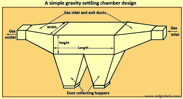
图 1 简单的重力沉降室设计
在分析沉降室的性能时,关键特征是通过设备的气流的性质。在这方面,可以区分三种基本的理想化流动情况,即(i)层流,(ii)活塞流(横截面上的速度均匀),没有颗粒垂直混合,以及(iii)活塞流完全垂直混合粒子。
层流的特征在于抛物线型速度分布。只有雷诺数低于过渡到湍流时才能实现这种流动。在层流中,在腔室地板上方高度为“h”的颗粒沉降所需的时间为“h/V”,其中 V 是颗粒的沉降速度。层流中不存在颗粒的垂直混合。相对于沉降引起的稳定向下运动,布朗运动的影响通常可以忽略不计。
在层流沉降室中,气体速度分布是抛物线形的,当中心流线下方的颗粒沉降时,它遇到移动更慢的流体,因此其在室中的停留时间比它在较高流线上的停留时间增加。另一方面,最初在中心流线上方的粒子在下落时会遇到移动速度更快的流线,直到它们通过中心流线。
第二类流动是没有颗粒垂直混合的活塞流。从某种意义上说,这种类型的流动近似于层流,因为仍然忽略了颗粒的垂直混合,但假定了平坦的速度分布,并且颗粒都以它们的沉降速度沉降。第二种流动情况是没有颗粒垂直混合的活塞流。在这种情况下,假设颗粒均匀分布在腔室的入口处。粒子是否被收集完全取决于其入口处收集表面上方的高度“h”。可以定义临界高度“h*”,使得所有“h”小于或等于“h*”的粒子都被收集,而那些“h”大于“h*”的粒子则逃逸收集。
第三类,完全垂直混合的活塞流,是湍流。在湍流沉降室中,由于湍流混合,假设气体速度在整个室中是均匀的。此外,腔室核心中的湍流混合压倒了颗粒沉降的趋势,并在整个腔室中垂直保持均匀的颗粒浓度。可以假设沉降去除发生在腔室底部的薄层中。
如果雷诺数大于 4,000,则可以假设矩形通道中的流动是湍流。在层流沉降室中,颗粒在沉降室地板上方的所有高度处沉降,分析的关键是计算颗粒在流线下落时的总停留时间。湍流沉降室中的收集机制虽然最终基于重力下颗粒的沉降,但与层流室中的收集机制有很大不同。差异是由于腔室中的湍流。在腔室中的整体流动中,湍流混合足够剧烈,以至于颗粒被流动淹没并且不会沉降。假设湍流混合在整个室的高度上保持均匀的颗粒浓度。非常靠近腔室的地板,可以假设存在一个薄层,颗粒在距离地板很短的距离内沉积在该层上。因此,一旦在流动核心中剧烈混合的颗粒进入该层,它就会沉降到地板上。
旋风分离器
旋风分离器是一种气体清洁装置,它利用旋转气流产生的离心力将颗粒与气体分离。标准切向入口垂直逆流旋风分离器如图 2 所示。气流被迫遵循旋风分离器的弯曲几何形状,而气流中颗粒的惯性使它们向外壁移动,在那里它们发生碰撞并被集。质量为“m”的粒子在半径为“r”的圆形路径中以切向速度“vA”运动,受到离心力“m(vA)2/r”的作用。 在“vA”=10 m/s、“r”=0.5 m 的典型值下,该力是同一粒子上重力的 20.4 倍。因此可以看出,对于旋风几何形状,颗粒上的作用力比单独沉降时显着增强。
在旋风分离器中,旋转气流中的颗粒在流经装置时逐渐靠近外壁。如图 2 所示,当气流从设备的一端流向另一端时,它可以执行几个完整的转弯。对于旋风分离器的设计,给定的气体流速和内外半径,旋风分离器主体的长度是为了确保对给定尺寸的颗粒达到所需的收集效率。由于旋风分离器的主体长度通过气体流速与气流执行的圈数相关,因此设计通常包括计算达到指定收集效率所需的圈数。
旋风分离器有多种设计,它们的不同之处在于将旋转运动传递给气流的方式。常规旋流器可分为三类,即(i)逆流旋流器(切向入口和轴向入口),(ii)直通式旋流器,以及(iii)叶轮收集器。
图 2 显示了具有切向入口的传统逆流旋流器。脏气体进入旋风分离器的顶部并由于其切向进入而产生旋转运动。颗粒在离心力的作用下被推向墙壁,然后由于重力而从墙壁上落下。在旋风分离器底部,气流反向形成内核,该内核在旋风分离器顶部离开。在逆流轴向入口旋流器中,入口气体沿旋流器轴线向下引入,顶部的永久叶片产生离心运动。
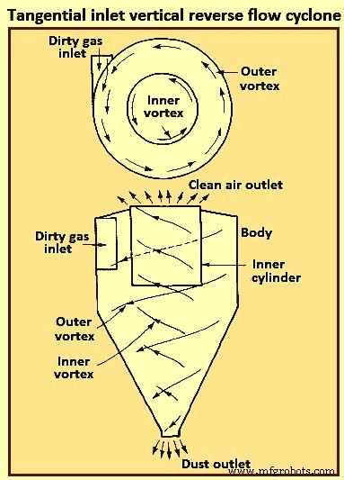
图2切向入口垂直逆流旋流器
在直通流旋风分离器中,空气的内部涡流在底部(而不是反向)离开,初始离心运动由顶部的叶片传递。这种类型经常用作去除大颗粒的预清洁剂。这种旋风分离器的主要优点是低压降和高体积流量。
在叶轮收集器中,气体垂直于多叶片叶轮进入,并被叶轮围绕其周边扫出,同时颗粒被抛入旋风分离器周边的环形槽中。这种旋风分离器的主要优点是其紧凑性。旋风分离器的主要缺点是由于旋风分离器中的固体堆积而容易堵塞。
旋风分离器可以由任何材料、金属或陶瓷制成。它们能够承受高温、磨粒或腐蚀性气氛。内表面必须光滑,以便收集的颗粒可以很容易地从壁上滑到料斗。旋风分离器中没有活动部件,因此操作通常简单且相对免维护。它们的低资本成本和免维护操作使其非常适合用作更高效的最终控制设备(如 ESP)的预清洁器。尽管旋风分离器传统上被认为是效率相对较低的收集器,但目前可用的一些旋风分离器对于大于 5 微米的颗粒可实现高于 98% 的效率。通常,旋风分离器对大于 15 微米到 20 微米的颗粒的效率通常为 90%。
图 3 显示了在 r3 处切向进入旋转气流的水平面上的粒子。由于“m(vA)2/r”的离心力,粒子沿着流线向外移动。其速度矢量具有切向分量 (vA) 和径向分量 (Vr)。还有一个轴向分量(vZ)。
所谓层流旋风分离器,不是层流沉降室意义上的层流,而是流线沿旋流器轮廓的无摩擦流动,如图3所示。
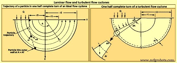
图3层流和湍流旋流器
湍流旋风分离器的模型如图 3 所示。由于湍流混合,假定整个旋风分离器的颗粒浓度是均匀的,并且与湍流沉降室的情况一样,在外墙。
旋风收集效率随着 (i) 颗粒大小、(ii) 颗粒密度、(iii) 入口气体速度、(iv) 旋风器主体长度、(v) 气体转数和 (vi) 旋风器壁的平滑度的增加而增加。另一方面,旋风分离器效率随着 (i) 旋风分离器直径、(ii) 气体出口管道直径和 (iii) 气体入口面积的增加而降低。对于任何特定的旋风分离器,其尺寸比是固定的,收集效率随着旋风直径的减小而提高。旋风分离器的设计代表了收集效率、压降和尺寸之间的折衷。更高的效率需要更高的压降(即入口气体速度)和更大的尺寸(即主体长度)。 The dimensions required to specify a tangential-entry, reverse-flow cyclone are shown in Fig 4.
Besides collection efficiency the other major consideration in cyclone specification is pressure drop. While higher efficiencies are achieved by forcing the gas through the cyclone at higher velocities, to do so results in an increased pressure drop. Since increased pressure drop needs increased energy input into the gas, there is ultimately an economic trade-off between collection efficiency and operating cost. Cyclone pressure drops normally range from 250 Pa to 4,000 Pa.
Electrostatic precipitator
ESP is one of the most widely used particulate control device. It has wide size ranges. The ESP chamber consists of two electrodes, the discharge and the collecting electrodes. Between the electrodes, the gas contains free electrons, ions, and charged particles. The species contributing to the space charge density are ions, electrons, and charged particles. The gas molecules capture all the free electrons so that only the ions and charged particles contribute space charge density. Actually, ionic current flows in the direction of the electric field consisting of ions charged with the same polarity as the charging electrode and moving to the collecting electrode. The ions migrate to the collecting electrode with a velocity large enough to be unaffected by the turbulent flow in the chamber.
The basic principle of operation of the ESP is that the particles are charged, and then an electric field is imposed on the region through which the particle-laden gas is flowing, exerting an attractive force on the particles and causing them to migrate to the oppositely charged electrode at right angles to the direction of gas flow. ESP differs from mechanical methods of particle separation in that the external force is applied directly to the individual particles rather than indirectly through forces applied to the entire gas stream (e.g. in a cyclone separator). Particles collect on the electrode. If the particles collected are liquid, then the liquid flows down the electrode by gravity and it is removed at the bottom of the device. If the particles are solid, the collected layer on the electrode is removed periodically by rapping the electrode.
Particle charging is achieved by generating ions by means of a corona established surrounding a highly charged electrode like a wire. The electric field is applied between that electrode and the collecting electrode. If the same pair of electrodes serves for particle charging and collecting, the device is called a single-stage ESP (Fig 4). A wire serving as the discharge electrode is suspended down the axis of a tube and held in place by a weight attached at the bottom. The sides of the cylinder form the collecting electrode. The collected particles which form a layer on the collecting electrode are removed to the dust hopper by rapping the collecting electrode. In a two-stage ESP, separate electrode pairs perform the charging and collecting functions.
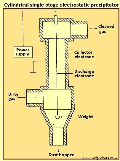
Fig 4 Cylindrical single-stage electrostatic precipitator
Most industrially generated particles are charged during their formation by such means as flame ionization and friction, but normally only to a low or moderate degree. These natural charges are far too low for electrostatic precipitation. The high-voltage DC (direct current) corona is the most effective means for particle charging and is universally used for electrostatic precipitation. The corona is formed between an active high voltage electrode such as a fine wire and a passive ground electrode such as a plate or pipe. The corona surrounding the discharge electrode can lead to the formation of either positive or negative ions which migrate to the collecting electrode. The ions, in migrating from the discharging to the collecting electrode, collide with the particulate matter and charge the particles.
Since the gas molecule ions are many orders of magnitude smaller than even the smallest particles and because of their great number, virtually all particles that flow through the device become charged. The charged particles are then transported to the collecting electrode, to which they are held by the electrostatic attraction. The particles build a thickening layer on the collecting electrode. The charge slowly bleeds from the particles to the electrode. As the layer grows, the charges on the most recently collected particles are to be conducted through the layer of previously collected particles. The resistance of the dust layer is called the dust resistivity.
As the particle layer grows in thickness, the particles closest to the plates lose most of their charge to the electrode. As a result, the electrical attraction between the electrode and these particles is weakened. However, the newly arrived particles on the outside layer have a full charge. Because of the insulating layer of particles, these new particles do not lose their charge immediately and thus serve to hold the entire layer against the electrode. Finally, the layer is removed by rapping, so that the layer breaks up and falls into a collecting hopper. ESPs are normally employed for gas cleaning when the volumetric throughput of gas is high.
The mechanism for particle charging in a ESP is the generation of a supply of ions which attach themselves to the particles. The corona is the mechanism for forming ions. The corona can be either positive or negative. A gas normally has a few free electrons and an equal number of positive ions, a situation which is exploited in generating a corona. When a gas is placed between two electrodes, small amount of current results as the free electrons migrate to the positive electrode and the positive ions migrate to the negative electrode.
In the positive corona discharge electrode, the wire in the cylindrical ESP (Fig 4) is at a positive potential. The few free electrons normally present in the gas migrate toward the wire. As the electrons approach the wire, the electrons’ energy is increased because of an increase in the attractive force. These free electrons collide with gas molecules, the collision leading in some cases to the ejection of an electron from the molecule, producing two free electrons and a positive ion. The two free electrons continue toward the positive electrode, gaining energy, until they collide with two more gas molecules, producing four free electrons and two positive ions. This process is referred to as an electron avalanche.
The positive ions formed migrate to the negative electrode. It is these positive ions which migrate across the entire device to the negative electrode that collide with and attach to the particles in the gas. The region immediately surrounding the wire in which the electron avalanche is established is the corona. Thus, with a positive corona the particles become positively charged. The term ‘corona’ arises from the fact that the electron avalanche is frequently accompanied by the production of light. In the negative corona the discharge electrode is maintained at a negative potential.
The electron avalanche begins at the outer surface of the wire and proceeds radially outward. Close to the wire the electrons are sufficiently energetic to form positive ions upon collision with gas molecules, thus initiating the electron avalanche. The positive ions formed migrate the short distance to the wire. As the electrons migrate outward into a region of lower electric field strength, they are slowed down by collisions with gas molecules. These electrons eventually have lower energy than those which are accelerated toward the positive electrode in the positive corona. These relatively low energy electrons, rather than ejecting an electron from the gas molecule upon collision, are absorbed by the gas molecules to produce negative ions. The formation of negative ions, which begins to occur at the outer edge of the corona, essentially absorbs all the free electrons produced in the electron avalanche at the wire surface. These negative ions then migrate to the positive electrode, in the course of which attaching to gas molecules and forming negative ions.
For a negative corona to be effective, it is necessary that the gas molecules can absorb free electrons to form negative ions. Sulphur dioxide is one of the best electron absorbing gases of those present in flue gases. Oxygen, CO2, and H2O are also effective electron absorbers. The negative corona is normally more stable than the positive corona, so it is preferred in most industrial applications. A by-product of the negative corona is the production of ozone (O3). The positive corona does not need an electron-absorbing gas.
As the ESP is operated, a layer of the collected material builds up on the collecting electrode. Particle deposits on the precipitator collection surface are to possess at least a small degree of electrical conductivity in order to conduct the ion currents from the corona to ground. The minimum conductivity required is around 10 to the power -10 per ohm-centimeter (resistivity of 10 to the power 10 ohm-centimeter). This conductivity is small compared to that of ordinary metals but is much greater than that of good insulators such as silica and most plastics. The resistivity of a material is determined by establishing a current flow through a slab of known thickness of the material.
As long as the resistivity of the collected dust layer is less than about 10 to the power 10 ohm-centimeter, the layer surrender its charge to the electrode. At the room temperature, a typical dust has a resistivity of around 10 to the power 8 ohm-centimeter. This is because of a layer of water on the surface of the particles. As the temperature is increased beyond 100 deg C, the water is evaporated and the resistivity increases to a value characteristic of the collected solids. When the resistivity of the layer exceeds around 10 to the power 10 ohm-centimeter, the potential across the layer increases so that the voltage which can be maintained across the ESP decreases and the collection efficiency decreases. The electrical resistivity of collected particulate matter depends on its chemical composition, the constituents of the gas, and the temperature.
Particle charging in ESP occurs in the gas space between the electrodes where the gas ions generated by the corona bombard and become attached to the particles. The gas ions can reach concentrations as high as 10 to the power 15 ions per cubic meter. The level of charge attained by a particle depends on the gas ion concentration, the electric field strength, the conductive properties of the particle, and the particle size. A 1 micrometer particle typically acquires the order of 300 electron charges, whereas a 10 micrometer particle can attain 30,000 electron charges. Predicting the level of charge acquired by a particle is necessary in order to predict the particle’s migration velocity, on the basis of which the collection efficiency can be calculated for a given set of operating conditions.
There are actually two mechanisms by which particles become charged in an ESP. In the first mechanism particle charging occurs when ions which are migrating toward the collecting electrode encounter particles to which they become attached. In migrating between the electrodes the ions follow the electric flux lines, which are curves everywhere tangent to the electric field vector. When the particle first enters the device and is uncharged, the electric flux lines deflect toward the particle, resulting in the capture of even a larger number of ions than are captured if the ions have followed their normal path between the electrodes. As the particle becomes charged, ions begin to be repelled by the particle, reducing the rate of charging. Eventually, the particle acquires a saturation charge and charging ceases. This mechanism is called ion bombardment or field charging.
The second mode of particle charging is diffusion charging, in which the particle acquires a charge by virtue of the random thermal motion of ions and their collision with and adherence to the particles. Diffusion charging occurs as the ions in their random thermal motion collide with a particle and surrender their charge to it. In that sense the mechanism of diffusion charging is identical to that of the diffusion of uncharged vapour molecules to the surface of a particle. However, because both the particle and the ions are charged, the random thermal motion of the ions in the vicinity of a particle is influenced by an electrostatic force. This force gives rise to a tendency of the ions to migrate away from the particle as the particle charge increases. The overall flux of ions to a particle hence is both the random diffusive motion and the electrical migration.
The theories of both field and diffusion charging, in their full generality, are quite complex and have received a great deal of attention. Strictly speaking, field and diffusion charging occur simultaneously once a particle enters an ESP, and hence to predict the overall charge acquired by a particle, one is to consider the two mechanisms together. However, since the diffusion charging is predominant for particles smaller than around 1 micrometer in diameter and field charging is predominant for particles larger than around 1 micrometer, the two mechanisms frequently are treated in ESP design as if they occur independently. In doing so, one estimates the total charge on a particle as the sum of the charges resulting from each of the two separate mechanisms.
Filtration of particles from gas streams
A major class of particulate air pollution control devices relies on the filtration of particles from gas streams. A variety of filter media is employed, including fibrous beds, packed beds, and fabrics. Fibrous beds used to collect airborne particles are typically quite sparsely packed, usually only around 10 % of the bed volume being fibers. Packed bed filters consist of solid packing normally in a tube and tend to have higher packing densities than do fibrous filters. Both fibrous and packed beds are widely used in the ventilation systems. Fabric filters are frequently used to remove solid particles from industrial gases, whereby the dusty gas flows through fabric bags and the particles accumulate on the cloth.
The physical mechanisms by which the filtration is accomplished vary depending on the mode of filtration. Conventional sparsely packed fibrous beds can be viewed as assemblages of cylinders. In such a filter, the characteristic spacing between fibers is much larger than the size of the particles being collected. Thus the mechanism of collection is not simply sieving, in which the particles are trapped in the void spaces between fibers. Rather, the removal of particles occurs by the transport of particles from the gas to the surface of a single collecting element. Because the filtration mechanisms in a fibrous bed can be analyzed in terms of a single collector, it is possible to describe them in considerable theoretical detail.
Packed-bed filters are sometimes viewed as assemblages of interacting, but essentially separate, spherical collectors, although the close proximity of individual packing elements casts doubt as to the validity of this approach. Because of the relatively closer packing in packed-bed filters, and the resulting difficulty of describing the particle collection process in clean theoretical terms, predicting collection in such systems is more empirically based than for fibrous filters. Fabric filter efficiencies must be predicted strictly empirically since the accumulated particle layer actually does the collecting.
A fibrous filter bed is viewed as a loosely packed assemblage of single cylinders. Even though the fibers are oriented in all directions in the bed, from a theoretical point of view the bed is treated as if every fiber is normal to the gas flow through the bed. The solid fraction of the filter is normally of the order of only 10 %. In addition, each fiber acts more or less independently as a collector. Thus, to compute the particle removal by a filter bed, one basically needs to determine the number of fibers per unit volume of the bed and then multiply that quantity by the efficiency of a single fiber.
The basis of predicting the collection efficiency of a filter bed is the collection efficiency of a single filter element in the bed. The filter element is taken as an isolated cylinder normal to the gas flow. Three distinct mechanisms as given below can be identified whereby particles in the gas reach the surface of the cylinder.
As per the first mechanism, the particles in a gas undergo Brownian diffusion which brings some particles in contact with the cylinder due to their random motion as they are carried past the cylinder by the flow. A concentration gradient is established after the collection of a few particles and acts as a driving force to increase the rate of deposition over that which occurs in the absence of Brownian motion. Because the Brownian diffusivity of particles increases as particle size decreases, it is normally expected that this removal mechanism is the most important for very small particles. When analyzing collection by Brownian diffusion, the particles are treated as diffusing mass-less points.
As per the second mechanism, interception takes place when a particle, following the streamlines of flow around a cylinder, is of a size sufficiently large that its surface and that of the cylinder come into contact. Thus, if the streamline on which the particle centre lies is within a distance Dp /2 of the cylinder, interception occurs. Here Dp is the particle diameter.
As per the third mechanism, inertial impaction occurs when a particle is unable to follow the rapidly curving streamlines around an obstacle and, because of its inertia, continues to move toward the obstacle along a path of less curvature than the flow streamlines. Thus, collision occurs because of the particle’s momentum. It is to be noted that the mechanism of inertial impaction is based on the premise that the particle has mass but no size, whereas interception is based on the premise that the particle has size but no mass.
Collection can also result from electrostatic attraction when either particles or fiber or both possess a static charge. These electrostatic forces can be either direct, when both particle and fiber are charged, or induced, when only one of them is charged. Such charges are normally not present unless deliberately introduced during the production of the fiber.
The size ranges in which the various mechanisms of collection are important are (i) Inertial impaction – greater than 1 micrometer, (ii) Interception – greater than 1 micrometer, (iii) diffusion – less than 0.5 micrometer, and (iv) electrostatic attraction – 0.01 micrometer to 5 micrometer. It is normal to analyze the mechanisms of collection separately and then combine the individual efficiencies to give the overall collection efficiency for the cylinder or other obstacle.
Most developments of particle collection assume, for lack of better information, that particles transported to the surface of a fiber are retained by the fiber. Experiments have shown, however, that for a variety of substances and filter media, the fraction of particles striking the collector surface which adhere is generally less than unity and can in some cases be as low as 0.5.
Industrial fabric filtration is normally accomplished in a so-called bag- house, in which the particle-laden gases are forced through filter bags. Particles are normally removed from the bags by gravity. Fig 5 shows three bag-house designs, in which cleaning is accomplished by vibration (Fig 5a), air jet [Fig 5b), or traveling ring [Fig 5c).
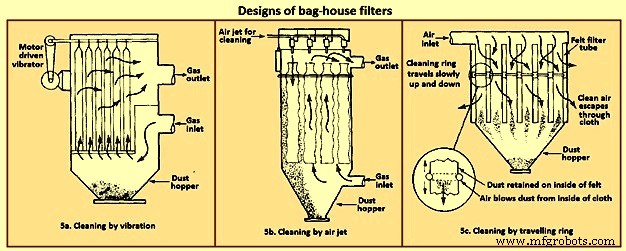
Fig 5 Designs of bag house filters
The fabric filtration process consists of three phases. First, particles collect on individual fibers by the above described mechanisms. Then an intermediate stage exists during which particles accumulate on previously collected particles, bridging the fibers. Finally, the collected particles form a cake in the form of a dust layer which acts as a packed bed filter for the incoming particles. As the dust layer accumulates, the pressure drop across the filter increases, and periodically the dust layer is to be dislodged into the hopper at the bottom to ‘regenerate’ the fabric bag. High efficiencies are attainable with fabric filters, particularly in treating combustion gases from the technological processes. To the extent that effective operation of an ESP depends on the presence of SO2 in the gas as an ionizable species, fabric filters can operate with no loss of efficiency with low-sulphur level.
Fabric filters consist of semi-permeable woven or felted materials which constitute a support for the particles to be removed. A brand-new woven filter cloth has fibers roughly 100 micrometers to 150 micrometers in diameter with open spaces between the fibers of 50 micrometers to 75 micrometers. Initially, the collection efficiency of such a cloth is low because most of the particles pass directly through the fabric. However, deposited particles quickly accumulate, and it is the deposited particle layer that enables the high-efficiency removal once a uniform surface layer has been established.
Although fiber mat filters are similar in some respects to fabric filters, they do not depend on the layer of accumulated particles for high efficiency. Fiber mat filters generally are not cleaned but are discarded. They are ordinarily used when particle concentrations are low, so that reasonable service life can be achieved before discarding.
In a fabric filter the particle layer performs the removal task. As the layer of collected particles grows in thickness, there is an increase in the pressure drop across the particle layer and the underlying fabric. The two major considerations in the design of a fabric filter assembly are the collection efficiency and the pressure drop as a function of time of operation (since the last cleaning). The collection efficiency depends on the local gas velocity and the particle loading on the fabric.
Fabric filters offer the several advantages such as (i) they can achieve very high collection efficiencies even for very small particles, (ii) they can be used for a wide variety of particles, (iii) they can operate over a wide range of volumetric flow rates, and (iv) they need only moderate pressure drops. The limitations of fabric filters are namely (i) operation is to be carried out at temperatures lower than that at which the fabric is destroyed, or its life is shortened to an uneconomical degree, (ii) gas or particle constituents which attack the fabric or prevent proper cleaning, such as sticky particles difficult to dislodge, are to be avoided, and (iii) bag houses need large floor areas. The advantages of fabric filter bag houses clearly outweigh their limitations.
Wet collectors
Wet collectors, or scrubbers, employ water washing to remove particles directly from a gas stream. Scrubbers can be grouped broadly into two main classes namely (i) those in which an array of liquid drops (sprays) form the collecting medium, and (ii) those in which wetted surfaces of various types constitute the collecting medium. The first class includes spray towers and venturi scrubbers, while the second includes plate and packed towers.
Scrubbing is a very effective means of removing small particles from a gas. Removal of particles results from collisions between particles and water drops. In the humid environment of a scrubber, small, dry particles also grow in size by condensation of water and thereby become easier to remove. Re-entrainment of particles is avoided since the particles become trapped in droplets or in a liquid layer. A scrubber also provides the possibility of simultaneously removing soluble gaseous pollutants. The particle-laden scrubbing liquid is to be disposed of, a problem not encountered in dry methods of gas cleaning.
A spray scrubber is a device in which a liquid stream is broken into drops, approximately in the range 0.1 mm to 1 mm in diameter, and introduced into the particle laden gas stream. The array of moving drops becomes a set of targets for collection of the particles in the gas stream. Collection efficiency is computed by considering the efficiency of a single spherical collector and then summing over the number of drops per unit volume of gas flow. The relative motion between the drops and particles is an important factor in the collection efficiency since capture occurs by impaction and direct interception. Diffusion is also important for smaller particles.
There are two general types of spray scrubbers. The first class comprises those having a preformed spray where drops are formed by atomizer nozzles and sprayed into the gas stream. These include (i) counter-current gravity tower, where drops settle vertically against the rising gas stream, (ii) cross-current tower, where drops settle through a horizontal gas stream, and (iii) co-current tower, where spray is horizontal into a horizontal gas stream.
The second class comprises those in which the liquid is atomized by the gas stream itself. Liquid is introduced more or less in bulk into a high-velocity gas flow which shatters the liquid into drops. Devices in this class are called venturi scrubbers since the high velocity gas flow is achieved in a venturi (a contraction). Fig 6 shows four types of wet collection equipment.
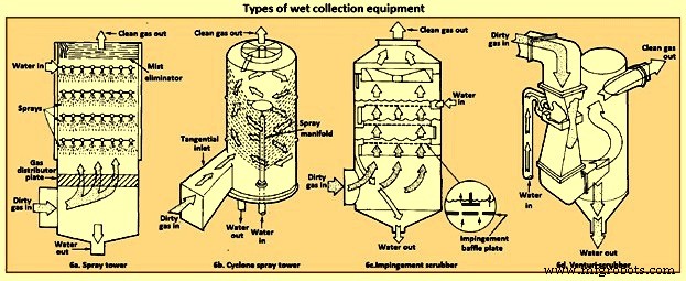
Fig 6 Types of wet collection equipment
The simplest type of wet collector is a spray tower into which water is introduced by means of spray nozzles (Fig 6a). Gas flow in a spray chamber is counter-current to the liquid, the configuration leading to maximum efficiency. Collection efficiency can be improved over the simple spray chamber with the use of a cyclonic spray tower, as shown in Fig 6b. The liquid spray is directed outward from nozzles in a central pipe. An unsprayed section above the nozzles is provided so that the liquid drops with the collected particles have time to reach the walls of the chamber before exit of the gas. An impingement plate scrubber, as shown in Fig 6c, consists of a tower containing layers of baffled plates with holes (5,000 to 50,000 per square meter) through which the gas must rise and over which the water must fall. Highest collection efficiencies of wet collectors are obtained in a venturi scrubber, shown in Fig 6d, in which water is introduced at right angles to a high-velocity gas flow in a venturi tube, resulting in the formation of very small water droplets by the flow and high relative velocities of water and particles. The high gas velocity is responsible for the breakup of the liquid. Aside from the small droplet size and high impingement velocities, collection is enhanced through particle growth by condensation. Different types of particle scrubbing devices are described below.
Plate scrubber – It is a vertical tower containing one or more horizontal plates (trays). Gas enters the bottom of the tower and must pass through perforations in each plate as the gas flows counter-current to the descending water stream. Plate scrubbers are normally named for the type of plates they contain (e.g. sieve plate tower). Collection efficiency increases as the diameter of the perforations decreases. A cut diameter, that collects with 50 % efficiency, of around 1 micrometer aerodynamic diameter can be achieved with 3.2 mm diameter holes in a sieve plate.
Packed-bed scrubber – It operates similarly to packed-bed gas absorber. Collection efficiency increases as packing size decreases. A cut diameter of 1.5 micrometers aerodynamic diameter can be attained in columns packed with 2.5 cm elements.
Spray scrubber – In this scrubber, particles are collected by liquid drops which have been atomized by spray nozzles. Horizontal and vertical gas flows are used, as well as spray introduced co-current, counter-current, or cross-flow to the gas. Collection efficiency depends on droplet size, gas velocity, liquid / gas ratio, and droplet trajectories. For droplets falling at their terminal velocity, the optimum droplet diameter for fine-particle collection lays in the range 100 micrometers to 500 micrometers. Gravitational settling scrubbers can achieve cut diameters of around 2 micrometers. The liquid / gas ratio is in the range 0.001 cum to 0.01 cum per cum of gas treated.
Venturi scrubber – A moving gas stream is used to atomize liquids into droplets. High gas velocities (60 m/sec to 120 m/s) lead to high relative velocities between gas and particles and promote collection.
Cyclone scrubber – Drops can be introduced into the gas stream of a cyclone to collect particles. The spray can be directed outward from a central manifold or inward from the collector wall.
Baffle scrubber – In this scrubber, there are changes in gas flow velocity and direction induced by solid surfaces.
Impingement-entrainment scrubber – The gas is forced to impinge on a liquid surface to reach a gas exit. Some of the liquid atomizes into drops which are entrained by the gas. The gas exit is designed so as to minimize the loss of entrained droplets.
Fluidized-bed scrubber – A zone of fluidized packing is provided where gas and liquid can mix intimately. Gas passes upward through the packing, while liquid is sprayed up from the bottom and / or flows down over the top of the fluidized layer of packing.
The collection efficiency of wet collectors can be related to the total energy loss in the equipment. The higher is the scrubber power per unit volume of gas treated, the better is the collection efficiency. Almost all the energy is introduced in the gas, and thus the energy loss can be measured by the pressure drop of gas through the unit. The major advantage of wet collectors is the wide variety of types, allowing the selection of a unit suitable to the particular removal problem. As regards disadvantages, high pressure drops (and hence energy requirements) are to be maintained, and the handling and disposal of large volumes of scrubbing liquid are to be undertaken.
In case of spray scrubbing, the conceptually simplest of the devices is a gravity spray chamber. Water droplets are introduced at the top of an empty chamber through atomizing nozzles and fall freely at their terminal settling velocities counter-currently through the rising gas stream. The particle-containing liquid collects in a pool at the bottom and is to be pumped out for treatment to remove the solids, and the cleaned liquid is normally recycled to the tower. The overall efficiency of a spray tower increases as the collection efficiency of a single drop increases, as the length of the chamber increases, and as the ratio of the volumetric flow rate of water to that of gas increases. It increases as the diameter of the drops decreases.
Venturi scrubbers are used when high collection efficiencies are needed and when most of the particles are smaller than 2 micrometers in diameter. There are a number of examples, in fact, where a venturi scrubber is the only practical device for a gas-cleaning application. If the particles to be removed are sticky, flammable, or highly corrosive, for example, ESPs and fabric filters cannot be used. Venturi scrubbers are also the only high-efficiency particulate collectors which can simultaneously remove gaseous species from the effluent stream.
The distinguishing feature of a venturi scrubber is a constricted cross section or throat through which the gas is forced to flow at high velocity. A typical venturi scrubber configuration is shown in Fig 7. The configuration includes a converging conical section where the gas is accelerated to throat velocity, a cylindrical throat, and a conical expander where the gas is slowed down. Liquid can be introduced either through tangential holes in the inlet cone or in the throat itself. In the former case, the liquid enters the venturi as a film on the wall and flows down the wall to the throat, where it is atomized by the high-velocity gas stream. In the latter, the liquid is injected perpendicular to the gas flow in the throat, atomized, and then accelerated. Gas velocities in the range 60 m/sec to 120 m/sec are achieved, and the high relative velocity between the particle laden gas flow and the droplets promotes collection. The collection process is essentially complete by the end of the throat. Because they operate at much higher velocities than ESPs precipitators or bag houses, venturi scrubbers are physically smaller and can be economically made of corrosion-resistant materials. Venturis have the simplest configuration of the scrubbers and are the smallest in size. Fig 7 shows the comparison of the efficiency of venturi scrubber with the efficiencies of other gas cleaning devices.
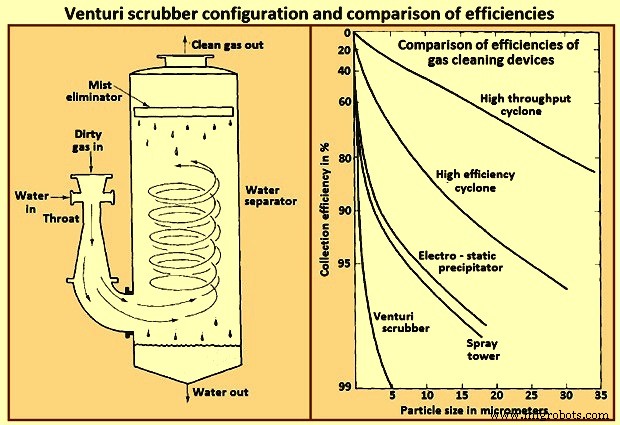
Fig 7 Venturi scrubber configuration and comparison of efficiencies
A typical range of liquid to gas flow rate ratios for a venturi scrubber is 0.001 cum to 0.003 cum of liquid per cum of gas. At the higher liquid / gas ratios, the gas velocity at a given pressure drop is reduced, and at lower ratios, the velocity is increased. For gas flow rates exceeding about 1,000 cum / minute venturi scrubbers are normally constructed in a rectangular configuration in order to maintain an equal distribution of liquid over the throat area.
制造工艺