

无损检测技术
无损检测技术
由于晶格缺陷,材料中可能存在固有的微观缺陷。此外,焊接、铸造、锻造和表面处理等制造工艺也会导致进一步的缺陷或缺陷。此外,材料在各种应力、疲劳和腐蚀条件下使用,这可能会产生额外的缺陷或加剧现有缺陷。当这些缺陷达到危险比例时,通常会发生材料失效,以至于材料的剩余部分无法承受其所承受的应力,从而变得易延展或变脆。因此,需要检测材料中的这些缺陷,并根据它们的性质、大小和位置对其进行评估。需要进一步的步骤来评估缺陷的严重程度,以决定材料是被接受、修复后被接受还是被拒收和报废。
无损检测 (NDT) 是检查、测试或评估材料、组件或组件的缺陷(也称为不连续性或特性差异)而不破坏零件或系统的可用性的技术。换句话说,当检查或测试完成时,零件仍然可以使用。该技术可以在抽样的基础上进行个别调查,也可以用于在生产质量控制系统中对材料进行 100% 检查。可以在不破坏其表面纹理、产品完整性和未来用途的情况下检查和/或测量材料或结构。
尽管 NDT 是一个高科技概念,但设备的发展使其足够强大,可以在任何制造阶段的任何工业环境中应用。它的应用范围从钢铁生产到已经投入使用的部件的现场检查。需要一定程度的技能才能正确应用 NDT 技术,以便获得有关产品的最大信息量,并随后反馈给生产设施。无损检测不仅仅是一种剔除不合格材料的方法,它也是一种确定所谓的好材料是好的保证。该技术使用多种原理。没有一种方法可以构建一个黑盒来满足所有情况下的所有要求
NDT 领域是一个非常广泛和跨学科的领域,在结构部件和系统的检查中起着至关重要的作用,以便它们以可靠的方式发挥其功能。还制定了某些标准以确保 NDT 测试的可靠性并防止由于所用设备的故障、方法的误用或检查员的技能和知识而导致的某些错误。成功的 NDT 测试可以定位和表征材料状况和缺陷。 NDT 技术通常需要相当高的操作技能,并且由于结果可能是主观的,因此很难准确解释测试结果。
NDT 技术名称通常指的是渗透介质的类型或用于执行测试的设备。 NDT 技术可分为常规技术和非常规技术。传统的 NDT 技术包括 (i) 视觉或光学检测,(ii) 液体渗透检测,(iii) 磁粉检测,(iv) 涡流检测,(v) 射线照相检测和 (vi) 超声波检测。非常规无损检测技术仅用于特殊应用,包括中子射线照相、声发射、红外检测、微波技术、泄漏检测、全息、导波检测、探地雷达和激光检测等。
大多数 NDT 技术共有的基本要素是(i)探测介质,(ii)适合所用介质的测试样品,以便可以检测到不连续性,(iii)能够测量分布或媒体的改变,(iv) 一种记录或显示从探测器接收到的适合评估的信息的技术,以及 (v) 受过训练以解释探测器反馈以评估结果的操作员。
NDA 技术在测试期间提供指示。适用于 NDT 的术语“适应症”的定义是“通过 NDT 披露的响应或响应的证据,需要进一步评估以确定其真正意义”。当对零件应用特定的 NDT 技术时,就会有响应。此响应是一个指示。术语“响应”旨在表示 (i) 执行液体渗透测试时的“渗出”,(ii) 执行磁粉测试时的颗粒堆积,(iii) 以防万一,射线照相胶片上的密度变化(iv) 执行超声波测试时的信号,以及 (v) 执行涡流测试时的仪表偏转、信号或数字变化。一旦观察到响应,执行测试的操作员需要对其进行解释,然后将其分类为任何一组指示,即 (i) 错误的、(ii) 不相关的或 (iii) 相关或真实的不连续性。
NDT 技术都没有为所有可能的问题提供解决方案,即它们不是可选的替代方案,而是相互补充。下面介绍传统技术的基本原理、典型应用、优点和局限性。
视觉或光学检查
视觉和光学检查技术(图 1)用于检查组件的表面状况。视觉测试被广泛用于几乎所有可能的表面条件。就其本质而言,视觉和光学测试可以简单直接。在最简单的情况下,操作员可以在没有设备的情况下在充足的光线下检查干净的组件,就这么简单。操作员经常需要使用光学设备来辅助检查,包括手持放大镜、灵活的光纤镜或远程视频系统。
经验丰富的操作员在最佳条件下甚至可以检测到很小的紧密裂缝。然而,可重复性是一个问题。如果条件未优化,同一操作员可能会在重复检查时错过同一组件上的同一裂纹。这就是为什么经常使用光学辅助设备为操作员提供尽可能多地发现故障情况的最佳机会。检查必须在清洁、舒适、照明充足的环境中进行。
应注意安全、工作位置和大气条件。检查需要操作者相当集中。照明非常重要,可以极大地影响结果。自然日光是进行目视检查的最佳光线类型。人造光也可用于目视检查,但操作者应确保所使用的规范或程序中规定的光照水平正确。
组件应清洁且无保护涂层,例如污垢或油漆会掩盖所寻求的表面条件。在进行目视检查之前,操作员有足够的培训和经验是非常重要的。操作者也要有良好的视力。众所周知,眼睛是一种极其精密的仪器,但它不能看到一切。它旨在将光线聚焦到视网膜上,将光线转换为神经冲动并将其发送到大脑。然后大脑处理这些信息并形成所看到的图像。这将我们引向感知,这是物理现实与检查员认为他们看到的视图之间的差异。不同的检查员对从眼睛传入的信息有不同的解释,因此他们对同一物理场景的看法略有不同。
Muller-Lyer 错觉(图 1)显示了感知与现实之间的差异。两个箭头的箭杆长度相同,但看起来不同。两名检查员之间的感知差异取决于培训和经验以及观察员在观察时的心理和身体状态。感知会受到疲劳和健康的影响。疲劳会降低观察者的效率和视觉能力。这些问题导致对物理数据的不准确解释。理想的检查是对培训、经验、照明和环境条件等所有因素进行优化的检查。
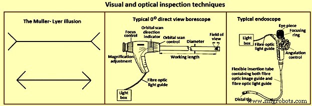
图 1 视觉和光学检测技术
从广义上讲,目视检查分为两种类型的查看技术。第一种技术是直接观察。在这种类型的对象查看中,对象就在操作员的眼前。这可以在没有帮助的情况下进行,也可以使用设备进行。二是远程观看。在这种情况下,对象的查看不是在操作员立即在场的情况下进行的。这是通过使用特殊设备完成的。
目视检查几乎可以成功应用于任何事物。它可用于定位许多不同类型的表面状况,从腐蚀或裂缝等不连续性到涂漆表面的斑驳效应。有经验的热处理操作人员甚至可以从外观上估算出部件在加热到白炽状态后的温度,例如暗樱桃红钢在 550 摄氏度左右。
操作员经常需要定位小的不连续性。肉眼很难做到这一点,因此需要光学辅助设备。一些最常见的光学辅助工具是 (i) 手持放大镜(通常从 1.5 倍放大到 10 倍放大),(ii) 带有测量刻度的测量放大镜,可以测量表面状况,例如角度泊放大镜,放大倍率高达 10 倍,通常内置圆形荧光管以提供均匀的照明,(iii) 各种类型的显微镜,具有多种放大倍率范围,(iv) 刚性管道镜,是优秀的用于检查管道或管道内部的设备(图 1),(v)称为内窥镜的类似设备(图 1),由于光导和图像导板都使用光纤,它比管道镜更灵活,以及( vi) 为了提高图像质量,管道镜的光学系统可以用一个微型摄像机代替,该摄像机可以包含一个像管,它使用电子束扫描一个称为光导目标的光导目标nsor,或者可以包含固态成像设备,例如电荷耦合设备或电荷注入设备。
液体渗透测试
液体渗透测试的基本原理(图 2)是,当将非常低粘度(高流动性)的液体(渗透剂)施加到零件表面时,它会渗透到表面开口的裂缝和空隙中。一旦多余的渗透剂被去除,被困在这些空隙中的渗透剂就会流回,从而产生指示。渗透测试可以对磁性和非磁性材料进行,但对多孔材料效果不佳。
为了降低灵敏度和降低成本,液体渗透剂工艺可分为(i)后乳化荧光染料渗透剂,(ii)溶剂可去除荧光染料渗透剂,(iii)水洗荧光染料渗透剂,(iv)后乳化可见染料渗透剂,(v) 溶剂可去除可见染料渗透剂,和 (vi) 水洗可见染料渗透剂。
液体渗透检测的优点是 (i) 成本相对较低,(ii) NDT 技术高度便携,(iii) 对精细、紧密的不连续性高度敏感,(iv) 适用于多种材料,以及 (v) 大面积检测.液体渗透技术的局限性在于 (i) 测试表面不得有任何污垢、油、油脂、油漆和铁锈等,(ii) 仅检测表面不连续性,(iii) 不能用于多孔和非常粗糙的表面,(iv)在测试后经常需要去除所有渗透材料,并且(v)没有简单的方法来产生永久记录。
在这种技术中,渗透剂可以是“可见的”,这意味着它们可以在环境光或荧光灯下看到,需要使用“黑”光。可见的染料渗透过程如图 2 所示。在进行液体渗透测试时,被测表面必须清洁且没有任何异物或液体,这些异物或液体会阻碍渗透剂进入开口于表面的空隙或裂缝。那个部分。应用渗透剂后,让其在表面上停留指定的时间(渗透剂停留时间),然后仔细清洁零件以去除表面多余的渗透剂。去除渗透剂时,操作者要小心不要去除任何流入空隙的渗透剂。然后在表面上涂上一层薄薄的显影剂,并提供一定的时间(显影剂停留时间)以使渗透剂从任何空隙或裂缝中渗入显影剂中,从而形成可见的指示。在规定的显影剂停留时间后,对零件进行目视检查或借助黑光检查荧光渗透剂。大多数显影剂是细粒状的白色滑石粉,与所使用的渗透剂形成颜色对比。
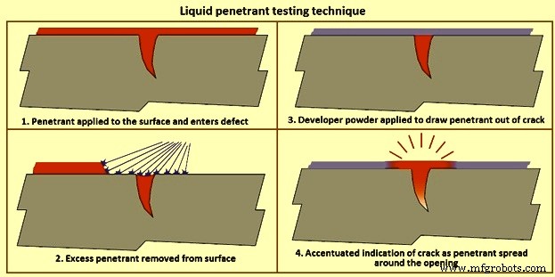
图2液体渗透检测技术
溶剂可去除渗透剂是那些需要除水以外的溶剂来去除过量渗透剂的渗透剂。这些渗透剂通常在自然界中可见,通常染成鲜红色,与白色显影剂形成鲜明对比。渗透剂通常喷洒或刷到部件上,然后在渗透剂停留时间结束后,用浸透渗透剂清洁剂的布清洁部件,然后涂上显影剂。在显影剂停留时间之后,检查部件以检测通过显影剂显示的任何渗透剂渗出。
可水洗渗透剂具有包含在渗透剂中的乳化剂,其允许使用喷水去除渗透剂。它们最常通过将零件浸入渗透剂罐中来应用,但可以通过喷涂或刷涂将渗透剂应用于大型零件。一旦部件被渗透剂完全覆盖,将部件放在排水板上等待渗透剂停留时间,然后将其带到冲洗站,在此用粗水喷淋清洗以去除多余的渗透剂。去除多余的渗透剂后,可以将零件放入暖风干燥机或温和的风扇前,直到水分被去除。然后可以将零件放入干燥的显影槽中并涂上显影剂,或者让其静置剩余的停留时间然后进行检查。
后乳化渗透剂是在其化学组成中不含乳化剂的渗透剂,如水洗渗透剂。后乳化渗透剂以类似的方式施加,但在水洗步骤之前,将乳化剂施加到表面上一段规定的时间(乳化剂停留时间)以去除过量的渗透剂。当乳化剂停留时间过去后,部件将进行与水洗渗透剂相同的水洗和显影过程。乳化剂可以是亲油性(油性)或亲水性(水性)。
磁粉检测
磁粉检测使用一个或多个磁场来定位铁磁材料中的表面和近表面不连续性。它用于定位铁磁材料中的表面和轻微的亚表面不连续性或缺陷。磁化零件中存在的此类缺陷会导致磁场(即磁通量)离开零件。如果将磁性颗粒施加到该表面上,它们会通过漏磁保持在适当的位置以提供视觉指示。虽然可以使用几种不同的磁粉测试方法,但它们都依赖于相同的一般原理。因此,任何磁粉测试都是通过在零件中产生磁场并将磁粉施加到测试表面来进行的。
磁场可以用永磁体或电磁体施加。使用电磁铁时,只有在施加电流时才会出现磁场。当磁场遇到垂直于磁场方向的不连续性时,磁力线会产生自身的漏磁磁场,如图 3 所示。这可以看出,当非常细的有色铁磁颗粒(磁性颗粒) 应用于零件表面,颗粒被吸入不连续处,从而减少气隙并在零件表面产生可见的指示。磁性粒子可以是干粉或悬浮在液体溶液中,可用可见染料或在紫外(黑)光下发荧光的荧光染料着色。
交流电 (AC) 或直流电 (DC) 均可用于感应磁场。由于“趋肤效应”,交流电产生的磁场在测试对象表面最强。 AC 还在零件表面提供更大的粒子流动性,使它们能够自由移动以定位漏磁区域,即使零件表面可能是不规则的。直流感应磁场具有更强的穿透力,可用于探测近地表不连续性。
大多数现场检查是使用磁轭进行的(图 3)。一个电线圈缠绕在中心铁芯上,当施加电流时,会产生一个磁场,该磁场从铁芯向下延伸通过铰接腿进入零件。这被称为纵向磁化,因为磁通量线从一条腿延伸到另一条腿。当腿放置在铁磁部件上并且磁轭被通电时,磁场被引入到部件中。由于磁通线从一条腿延伸到另一条腿,因此可以找到垂直于在腿之间绘制的线的不连续性。为确保不遗漏指示,将轭架在如图所示位置使用一次,然后将轭架旋转 90 度再次使用,以免遗漏指示。因为所有的电流都包含在磁轭中,只有磁场穿透零件,所以这种应用也称为间接感应。
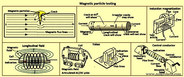
图3磁粉检测
戳单元使用直接感应,其中电流流过零件并在腿周围产生圆形磁场,如图 3 所示。由于戳之间的磁场垂直于戳之间绘制的线,因此指示平行定向可以找到在戳之间绘制的线。与轭一样,要进行两次检查,第二次检查的方向是与第一次应用呈 90 度角。
电线圈用于产生纵向磁场。通电时,电流会在构成线圈的导线周围产生磁场,从而使产生的磁通线定向通过线圈。由于存在纵向场,放置在线圈中的零件的指示横向于纵向场。
大多数卧式湿浴机(台式装置)都有一个线圈和一组头部,电流可以通过这些头部,产生磁场。这些机器在液体溶液中使用荧光磁性颗粒,因此得名“湿浴”。在测试头之间的零件时,将零件放在头之间,向上移动可移动头,使被测零件紧紧地夹在头之间,用含有磁性颗粒的浴液润湿零件,然后在粒子流过零件时施加电流。由于电流从头到头流动,并且磁场与电流呈 90 度角,因此可以看到与头之间的线平行的指示。这种检查通常被称为“爆头”。
在测试管道、管子和管件等中空部件时,可以将导电圆形棒放置在头部之间,并将部分悬挂在棒(中心导体)上,如图 3 所示。然后用浴液润湿部件并且施加电流,通过中心导体而不是通过零件。然后可以检查零件的 ID 和 OD。与爆头的情况一样,磁场垂直于电流流动,缠绕在测试件周围,因此使用这种技术可以找到沿零件长度轴向延伸的迹象。
磁粉检测的优点是(i)经济,(ii)有助于目视检测,(iii)可以是固定或便携式设备,(iv)提供即时可重复的结果,(v)有效的检测技术,以及( vi) 对比剂或荧光耗材。磁粉检测的局限性在于 (i) 被检查的零件是铁磁性的,(ii) 需要高电流,(iii) 只能检测表面和轻微亚表面缺陷,(iv) 零件需要去磁,(v) 零件要干净且相对光滑,(vi) 设备可能笨重,(vi) 通常需要电源,(vii) 涂层可以掩盖迹象,以及 (viii) 材料或零件的渗透性可以影响结果。
涡流检测
涡流是通过称为电磁感应的过程产生的。当交流电应用于导体(例如铜线)时,会在导体内部和周围产生磁场。该磁场随着交流电上升到最大值而扩展,并随着电流减小到零而崩溃。如果另一个电导体靠近这个变化的磁场,则在这个第二个导体中感应出电流。这些电流受材料性质的影响,例如空隙、裂纹、晶粒尺寸的变化以及线圈和材料之间的物理距离。这些电流在用作传感器的第二个线圈上形成阻抗。在实践中,将探头放置在要检查的零件表面上,电子设备通过同一探头监测工件中的涡流。感应电路是发送线圈的一部分。
涡流技术的主要应用是检测表面或亚表面缺陷。该技术对产品的材料导电性、渗透性和尺寸敏感。涡流可以在任何受到交变磁场(通常为 10 Hz 至 10 MHz)的导电材料中产生。交变磁场通常通过使交流电流通过线圈来产生。线圈可以有多种形状,并且可以有 10 匝到 500 匝之间的导线。产品中产生的涡流大小取决于电导率、磁导率和设置几何形状。材料或几何形状的任何变化都可以被励磁线圈检测为线圈阻抗的变化。
最简单的线圈包括一根铁氧体棒,其一端绕有几匝线,靠近待测产品的表面定位。例如,当产品表面出现裂纹时,涡流会在裂纹周围传播得更远,这可以通过阻抗变化来检测(图 4)。线圈也可以成对使用,通常称为驱动对,这种布置可以与差分连接的线圈一起使用。通过这种方式,可以增强“升空”(探头与表面的距离)信号。线圈也可用于变压器类型的配置,其中一个线圈绕组是初级,一个(或两个)线圈绕组用于次级。 .
检测到的涡流信号包含幅度和相位信息,这些信息可以显示在 CRT(阴极射线管)类型的显示器上,通常是非数字显示器。信号可以显示为实际信号,即绝对信号,或使用适当的电子设备,仅显示信号变化。只有一个产品参数发生变化时,例如:裂缝的存在。实际上,涡流信号的变化是由成分、硬度、质地、形状、导电性、渗透性和几何形状的差异引起的。在某些情况下,裂缝的影响可能会被其他参数的变化所掩盖,并且可能会发生不必要的拒绝。但是,可以根据需要选择线圈的配置、尺寸和测试频率,以增强对裂纹、导电性、金属损耗等的检测。
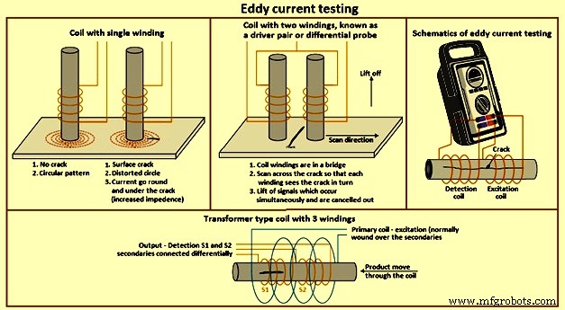
图4涡流检测
涡流穿透材料的深度可以通过调整测试频率来改变,即频率越高,穿透越低。然而,频率越低,对小缺陷的敏感度就越低。较大的线圈对表面粗糙度不太敏感,反之亦然。最新的电子单元能够以绝对模式或差分模式以及在广泛的频率范围内操作各种线圈配置。对于单个或复杂形状部件的裂纹表面测试,通常使用具有单个铁氧体芯绕组的线圈。探头放置在组件上并通过使用电子单元控制“平衡”。当探头扫描组件表面时,可以检测到裂纹。
在要自动扫描表面的情况下,只有在准确保持离地距离的情况下,单线圈绕组才适用。通常差分线圈配置与高速扫描系统一起使用,其中可以在可接受的范围内消除提升效应、振动效应等。管材、棒材和线材可以使用环形线圈进行检测,这些线圈通常采用一个初级和两个差动连接的次级线圈配置。
大多数涡流电子设备都有相位显示,这使操作员能够识别缺陷状况。在许多情况下,可以清楚地识别来自裂纹、剥离和其他参数的信号。还提供可以在两个或多个不同测试频率下同时检查产品的单元。这些单元允许以电子方式消除特定的不需要的影响,从而改进缺陷检测。
涡流测试是纯电气的。线圈单元不需要接触产品表面,因此该技术可以很容易地自动化。大多数自动化系统适用于简化机械处理的简单几何形状的组件。
涡流检测的优点是(i)适用于确定导电材料的各种条件,例如各种工程金属中的缺陷检测、成分、硬度、电导率、磁导率等,(ii)信息可以通过简单的术语经常提供,因为可以使用相位显示电子装置来获得更多的产品信息,(iii) 提供极其紧凑和便携的装置,(iv) 没有消耗品(除了有时可以(v) 灵活选择探头和测试频率以适应不同的应用,以及 (vi) 适用于完全自动化。涡流检测的缺点是 (i) 影响涡流响应的参数范围很广,这意味着来自所需材料特性的信号,例如裂缝,可以被不需要的参数掩盖,例如硬度变化,因此在某些应用中需要仔细选择探头和电子设备,并且(ii)通常会限制测试
射线检测
射线照相测试方法用于检测许多不同材料和配置的内部缺陷。由电产生的 X 射线和放射性同位素发射的伽马射线是穿透性辐射,被它通过的材料不同地吸收。厚度越大,吸收越大。此外,材料越致密,吸收越大。 X 射线和伽马射线也具有与光一样的特性,可将照相胶片中的卤化银晶体部分转化为金属银,与到达胶片的辐射强度成比例,从而形成潜像。这可以像普通摄影胶片一样进行显影和定影(图5)。
通过将对象置于辐射源和胶片之间来测试具有内部空隙的材料。在清晰的背景上,空隙显示为黑暗区域,更多辐射到达薄膜。 X射线和伽马射线照相的原理是相同的。
在 X 射线摄影中,穿透力由施加到 X 射线管的伏特数决定。在钢的情况下,它约为每英寸厚度 1,000 伏特。在伽马射线照相中,同位素控制着穿透力,并且在每种同位素中都是不可改变的。因此,铱 192 用于 15 毫米至 25 毫米厚的钢,铯 134 用于 20 毫米至 265 毫米厚的钢。在 X 射线照相术中,强度和曝光时间由管中阴极的安培数决定。暴露时间通常以毫安分钟表示。对于伽马射线,辐射强度是在供应同位素时设定的。同位素辐射的强度以贝克勒尔为单位,并在一段时间内降低。衰变到一半居里所用的时间就是半衰期,是每种同位素的特征。例如铱192的半衰期为74天,铯134的半衰期为2.1年。
暴露因子是居里数和时间的乘积,通常以居里小时表示。随着同位素衰变,暴露时间将增加。当暴露时间变得不经济时,同位素将被更新。 As the isotope is continuously emitting radiation it is to be housed in a container of depleted uranium or similar dense shielding material, whilst not exposed for protecting the environment and personnel.
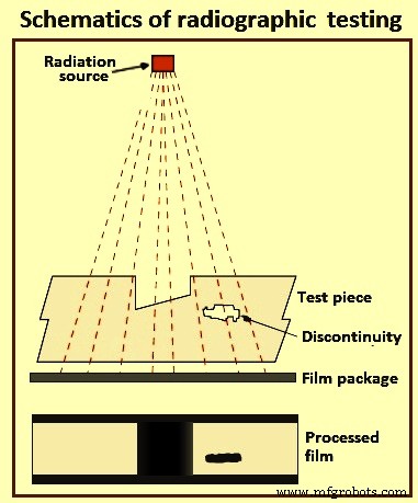
Fig 5 Schematics of radiographic testing
To produce an x-ray or gamma ray radiograph, the film package ((enclosed in a light tight cassette and comprising film and intensifying screens, the latter being required to reduce the exposure time) is placed close to the surface of the subject. The source of radiation is positioned on the other side of the subject some distance away, so that the radiation passes through the subject and on to the film. After the exposure period the film is removed, processed, dried, and then viewed by transmitted light on a special viewer. Different radiographic and photographic accessories are necessary, including such items as radiation monitors, film markers, image quality indicators, dark-room equipment, etc. As far as the last is concerned there are many degrees of sophistication, including fully automatic processing units. These accessories are the same for both x-ray and gamma radiography systems. Also needed are such consumable items as radiographic film and processing chemicals
Recent developments in radiography permit ‘real time’ diagnosis. Such techniques as computerized tomography yield much important information, though these methods can be suitable for only investigative purposes and not generally employed in production quality control.
Industrial radiography involves exposing a test object to penetrating radiation so that the radiation passes through the object being inspected and a recording medium placed against the opposite side of that object. For thinner or less dense materials such as aluminum, electrically generated x-radiations (x-rays) are normally used, and for thicker or denser materials, gamma radiation is generally used. Gamma radiation is given off by decaying radioactive materials, with the two most commonly used sources of gamma radiation being Iridium-192 (Ir-192) and Cobalt-60 (Co-60). Ir-192 is normally used for steel upto 15 mm to 25 mm, depending on the Curie strength of the source, and Co-60 is normally used for thicker materials due to its greater penetrating ability. The recording media can be industrial x-ray film or one of several types of digital radiation detectors. With both, the radiation passing through the test object exposes the media, causing an end effect of having darker areas where more radiation has passed through the part and lighter areas where less radiation has penetrated. If there is a void or defect in the part, more radiation passes through, causing a darker image on the film or detector.
Film radiography uses a film made up of a thin transparent plastic coated with a fine layer of silver bromide on one or both sides of the plastic. When exposed to radiation these crystals undergo a reaction which allows them, when developed, to convert to black metallic silver. This silver is then ‘fixed’ to the plastic during the developing process, and when dried, becomes a finished radiographic film. To be a usable film, the area of interest on the film is to be within a certain density (darkness) range and is to show enough contrast and sensitivity so that discontinuities of interest can be seen. These items are a function of the strength of the radiation, the distance of the source from the film and the thickness of the part being inspected. If any of these parameters are not met, another exposure (is to be made for that area of the part.
Computed radiography is a transitional technology between film and direct digital radiography. This technique uses a reusable, flexible, photo-stimulated phosphor plate which is loaded into a cassette and is exposed in a manner similar to traditional film radiography. The cassette is then placed in a laser reader where it is scanned and translated into a digital image, which take from one to five minutes. The image can then be uploaded to a computer or other electronic media for interpretation and storage. Computed tomography uses a computer to reconstruct an image of a cross sectional plane of an object as opposed to a conventional radiograph. The computed tomography image is developed from multiple views taken at different viewing angles which are reconstructed using a computer. With traditional radiography, the position of internal discontinuities cannot be accurately determined without making exposures from several angles to locate the item by triangulation. With computed tomography, the computer triangulates using every point in the plane as viewed from many different directions.
Digital radiography digitizes the radiation which passes through an object directly into an image which can be displayed on a computer monitor. The three principle technologies used in direct digital imaging are amorphous silicon, charge coupled devices, and complementary metal oxide semi-conductors. These images are available for viewing and analysis in seconds compared to the time needed to scan in computed radiography images. The increased processing speed is a result of the unique construction of the pixels; an arrangement which also allows a superior resolution than is found in computed radiography and most film applications.
The advantages of radiographic testing include (i) is useful on wide variety of materials, (ii) can be used for checking internal mal-structure, misassembly or misalignment, (iii) provides permanent record, and (iv) devices for checking the quality of radiograph are available. Some of the limitations of this method are (i) access to both sides of the object is needed, (ii) cannot detect planar defects readily, (iii) thickness range which can be inspected is limited, (iv) sensitivity of inspection decreases with thickness of the test object, (v) considerable skill is needed for interpretation of the radiographs, (vi) depth of defect is not indicated readily, and (vii) x-rays and gamma rays are hazardous to human health.
Ultrasonic testing
Ultrasonic technique is used for the detection of internal and surface (particularly distant surface) defects in sound conducting materials. The principle is in some respects similar to echo sounding. A short pulse of ultrasound is generated by means of an electric charge applied to a piezo electric crystal, which vibrates for a very short period at a frequency related to the thickness of the crystal. In flaw detection, this frequency is normally in the range of one million to six million times per second (1 MHz to 6 MHz). Vibrations or sound waves at this frequency have the ability to travel a considerable distance in homogeneous elastic material, such as many metals with little reduction. The velocity at which these waves propagate is related to the Young’s Modulus for the material and is characteristic of the material. For example the velocity in steel is 5,900 metres per second, and in water 1,400 metres per second.
Ultrasonic energy is considerably reduced in air, and a beam propagated through a solid, on reaching an interface (e.g. a defect, or intended hole, or the back wall) between that material and air reflects a considerable amount of energy in the direction equal to the angle of incidence. For contact testing the oscillating crystal is incorporated in a hand held probe, which is applied to the surface of the material to be tested. To facilitate the transfer of energy across the small air gap between the crystal and the test piece, a layer of liquid (referred to as ‘couplant’), usually oil, water or grease, is applied to the surface. The crystal does not oscillate continuously but in short pulses, between each of which it is quiescent.
Piezo electric materials not only convert electrical pulses to mechanical oscillations, but also transduce mechanical oscillations into electrical pulses. Hence, there is not only a generator of sound waves but also a detector of returned pulses. The crystal is in a state to detect returned pulses when it is quiescent. The pulse takes a finite time to travel through the material to the interface and to be reflected back to the probe.
The standard method of presenting information in ultrasonic testing is by means of a cathode ray tube, in which horizontal movement of the spot from left to right represents time elapsed. The principle is not greatly different in digitized instruments that have a LCD (liquid crystal display) flat screen. The rate at which the spot moves is such that it gives the appearance of a horizontal line on the screen. The system is synchronized electronically so that at the instant the probe receives its electrical pulse the spot begins to traverse the screen. An upward deflection (peak) of the line on the screen is an indication of this occurrence. This peak is normally termed the initial pulse.
Whilst the base line is perfectly level the crystal is quiescent. Any peaks to the right of the initial pulse indicate that the crystal has received an incoming pulse reflected from one or more interfaces in the material. Since the spot moves at a very even speed across the tube face, and the pulse of ultrasonic waves moves at a very even velocity through the material, it is possible to calibrate the horizontal line on the screen in terms of absolute measurement. The use of a calibration block, which produces a reflection from the back wall a known distance away from the crystal together with variable controls on the flaw detector, allows the screen to be calibrated in units of distance, and hence determination of origins of returned pulses obtained from a test piece.
It is hence possible not only to discover a defect between the surface and the back wall, but also to measure its distance below the surface. It is important that the equipment is properly calibrated and, since it is in itself not able to discriminate between intended boundaries of the object under test and unintended discontinuities, the operator is required to identify the origin of each peak. Further as the pulses form a beam it is also possible to determine the plan position of a flaw. The height of the peak (echo) is roughly proportional to the area of the reflector, though there is on all instruments a control, which can reduce or increase the size of an indication – variable sensitivity in fact. Not only is part of the beam reflected at a material / air interface but also at any junction where there is a velocity change, for example steel / slag interface in a weld.
Probing all faces of a test piece not only discovers the three-dimensional defect and measures its depth, but can also determine its size. Two-dimensional (planar) defects can also be found but, unlike radiography, it is best that the incident beam impinges on the defect as near to right angles to the plane as possible. To achieve this some probes introduce the beam at an angle to the surface. In this manner longitudinal defects in tubes (inner or outer surface) are detected.
Interpretation of the indications on the screen requires a certain amount of skill, particularly when testing with hand held probes. The technique is, however, admirably suited to automatic testing of regular shapes by means of a monitor – an electronic device which fits into the main equipment to provide an electrical signal when an echo occurs in a particular position on the trace. The trigger level of this signal is variable and it can be made to operate a variety of mechanical gates and flaw warnings. Furthermore, improvements in computer technology allow test data and results to be displayed and out-putted in a wide variety of formats.
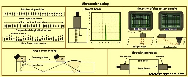
Fig 6 Ultrasonic testing
Modern ultrasonic flaw detectors are fully solid state and can be battery powered, and are robustly built to withstand site conditions. Since the velocity of sound in any material is characteristic of that material, it follows that some materials can be identified by the determination of the velocity. This can be applied, for example in spheroidal graphite cast irons to determine the percentage of graphite nodularity.
When the velocity is constant, as it is in a wide range of steels, the time taken for the pulse to travel through the material is proportional to its thickness. Hence, with a properly calibrated instrument, it is possible to measure thickness from one side with accuracy in hundredths of a millimeter. This technique is now in very common use. A development of the standard flaw detector is the digital wall thickness gauge. This operates on similar principles but gives an indication, in LED (light emitting diode) or LCD 9liquid crystal display) numerics, of thickness in absolute terms of millimetres. These equipments are easy to use but need prudence in their application.
The two most commonly used types of sound waves used in industrial inspections are the compression (longitudinal) wave and the shear (transverse) wave (Fig 6). Compression waves cause the atoms in a part to vibrate back and forth parallel to the sound direction and shear waves cause the atoms to vibrate perpendicularly (from side to side) to the direction of the sound. Shear waves travel at around half the speed of longitudinal waves. Sound is introduced into the part using an ultrasonic transducer (probe) which converts electrical impulses from the ultrasonic testing machine into sound waves, then converts returning sound back into electric impulses which can be displayed as a visual representation on a digital or LCD screen. If the machine is properly calibrated, the operator can determine the distance from the transducer to the reflector, and in many cases, an experienced operator can determine the type of discontinuity which caused the reflector. Because ultrasound does not travel through air (the atoms in air molecules are too far apart to transmit ultrasound), a liquid or gel called ‘couplant’ is used between the face of the transducer and the surface of the part to allow the sound to be transmitted into the part.
Straight beam inspection uses longitudinal waves to interrogate the test piece as shown at the right. If the sound hits an internal reflector, the sound from that reflector reflects to the transducer faster than the sound coming back from the back-wall of the part due to the shorter distance from the transducer. This results in a screen display. Digital thickness testers use the same process, but the output is shown as a digital numeric readout rather than a screen presentation.
Angle beam inspection uses the same type of transducer but it is mounted on an angled wedge (also called a probe) that is designed to transmit the sound beam into the part at a known angle. The most commonly used inspection angles are 45 degrees, 60 degrees, and 70 degrees, with the angle being calculated up from a line drawn through the thickness of the part (not the part surface). A 60 degree probe is shown in Fig 6. If the frequency and wedge angle is not specified by the governing code or specification, it is upto the operator to select a combination which adequately inspects the part being tested. In angle beam inspections, the transducer and wedge combination (also referred to as a probe) is moved back and forth towards the weld so that the sound beam passes through the full volume of the weld. As with straight beam inspections, reflectors aligned more or less perpendicular to the sound beam sends sound back to the transducer and are displayed on the screen.
Immersion Testing is a technique where the part is immersed in a tank of water with the water being used as the coupling medium to allow the sound beam to travel between the transducer and the part. The ultrasonic testing machine is mounted on a movable platform (a bridge) on the side of the tank so it can travel down the length of the tank. The transducer is swivel-mounted on at the bottom of a waterproof tube which can be raised, lowered and moved across the tank. The bridge and tube movement permits the transducer to be moved on the X-, Y- and Z-axes. All directions of travel are gear driven so the transducer can be moved in accurate increments in all directions, and the swivel allows the transducer to be oriented so the sound beam enters the part at the required angle. Round test parts are frequently mounted on powered rollers so that the part can be rotated as the transducer travels down its length, allowing the full circumference to be tested. Multiple transducers can be used at the same time so that multiple scans can be performed.
Through transmission inspections are performed using two transducers, one on each side of the part (Fig 6). The transmitting transducer sends sound through the part and the receiving transducer receives the sound. Reflectors in the part cause a reduction in the amount of sound reaching the receiver so that the screen presentation shows a signal with lower amplitude (screen height).
Phased array inspections are done using a probe with multiple elements which can be individually activated. By varying the time when each element is activated, the resulting sound beam can be steered, and the resulting data can be combined to form a visual image representing a slice through the part being inspected.
Time of flight diffraction uses two transducers located on opposite sides of a weld with the transducers set at a specified distance from each other. One transducer transmits sound waves and the other transducer acting as a receiver. Unlike other angle beam inspections, the transducers are not manipulated back and forth towards the weld, but travel along the length of the weld with the transducers remaining at the same distance from the weld. Two sound waves are generated, one travelling along the part surface between the transducers, and the other travelling down through the weld at an angle then back up to the receiver. When a crack is encountered, some of the sound is diffracted from the tips of the crack, generating a low strength sound wave which can be picked up by the receiving unit. By amplifying and running these signals through a computer, defect size and location can be determined with much greater accuracy than by conventional ultrasonic testing methods.
The advantages of ultrasonic flaw detection include (i) thickness and lengths upto 10 meter can be tested, (ii) position, size and type of defect can be determined, (iii) instant test results, (iv) portable, (v) extremely sensitive if required, (vi) capable of being fully automated, (vi) access to only one side necessary, and (vii) no consumables needed. The disadvantages of ultrasonic flaw detection include (i) no permanent record available unless one of the more sophisticated test results and data collection systems is used, (ii) the operator can decide whether the test piece is defective or not whilst the test is in progress, (iii) indications need interpretation, (iv) considerable degree of skill
制造工艺