

4位计数器
4 位计数器开始从 4'b0000 递增到 4'h1111,然后返回到 4'b0000。只要它有一个运行时钟并且复位保持高电平,它就会一直计数。
当最终添加的最重要位被丢弃时,就会发生翻转。当计数器达到最大值 4'b1111 并再收到一个计数请求时,计数器会尝试达到 5'b10000,但由于它只能支持 4 位,因此 MSB 将被丢弃,导致为 0。
	0000
	0001
	0010
	...
	1110
	1111
	       rolls over
	0000
	0001
	...
该设计包含两个输入,一个用于时钟,另一个用于低电平有效复位。低电平有效复位是指当复位引脚的值为 0 时复位设计。有一个 4 位输出调用,它本质上提供计数器值。
<无脚本>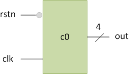
电子计数器设计
module counter (  input clk,               // Declare input port for clock to allow counter to count up
                  input rstn,              // Declare input port for reset to allow the counter to be reset to 0 when required
                  output reg[3:0] out);    // Declare 4-bit output port to get the counter values

  // This always block will be triggered at the rising edge of clk (0->1)
  // Once inside this block, it checks if the reset is 0, if yes then change out to zero
  // If reset is 1, then design should be allowed to count up, so increment counter
  always @ (posedge clk) begin
    if (! rstn)
      out <= 0;
    else
      out <= out + 1;
  end
endmodule
module 计数器有一个时钟和低电平有效复位(用 n 表示 ) 作为输入,计数器值作为 4 位输出。 always 块是总是 每当时钟从 0 转变为 1 时执行,这表示上升沿或上升沿。只有当 reset 保持高电平或 1 时,输出才会递增,由 if-else 实现 堵塞。如果在时钟上升沿发现复位为低电平,则输出复位为默认值 4'b0000。
测试台
我们可以将设计实例化到我们的测试平台模块中,以验证计数器是否按预期计数。
<无脚本>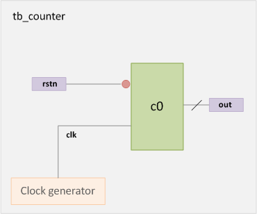
测试台模块名为 tb_counter 并且不需要端口,因为这是模拟中的顶级模块。然而,我们确实需要有内部变量来生成、存储和驱动时钟以及复位。为此,我们声明了两个 reg 类型的变量 时钟和复位。我们还需要一个 wire 键入 net 以与设计的输出建立连接,否则它将默认为 1 位标量网络。
时钟通过 always 生成 块将给出 10 个时间单位的周期。 initial 块用于为我们的内部变量设置初始值,并将复位值驱动到设计中。设计是实例化的 在测试台中并连接到我们的内部变量,以便当我们从测试台驱动它们时它会获取值。我们没有任何 $display 测试台中的语句,因此我们不会在控制台中看到任何消息。
module tb_counter;
  reg clk;                     // Declare an internal TB variable called clk to drive clock to the design
  reg rstn;                    // Declare an internal TB variable called rstn to drive active low reset to design
  wire [3:0] out;              // Declare a wire to connect to design output

  // Instantiate counter design and connect with Testbench variables
  counter   c0 ( .clk (clk),
                 .rstn (rstn),
                 .out (out));

  // Generate a clock that should be driven to design
  // This clock will flip its value every 5ns -> time period = 10ns -> freq = 100 MHz
  always #5 clk = ~clk;

  // This initial block forms the stimulus of the testbench
  initial begin
    // 1. Initialize testbench variables to 0 at start of simulation
    clk <= 0;
    rstn <= 0;

    // 2. Drive rest of the stimulus, reset is asserted in between
    #20   rstn <= 1;
    #80   rstn <= 0;
    #50   rstn <= 1;

    // 3. Finish the stimulus after 200ns
    #20 $finish;
  end
endmodule
模拟日志ncsim> run [0ns] clk=0 rstn=0 out=0xx [5ns] clk=1 rstn=0 out=0x0 [10ns] clk=0 rstn=0 out=0x0 [15ns] clk=1 rstn=0 out=0x0 [20ns] clk=0 rstn=1 out=0x0 [25ns] clk=1 rstn=1 out=0x1 [30ns] clk=0 rstn=1 out=0x1 [35ns] clk=1 rstn=1 out=0x2 [40ns] clk=0 rstn=1 out=0x2 [45ns] clk=1 rstn=1 out=0x3 [50ns] clk=0 rstn=1 out=0x3 [55ns] clk=1 rstn=1 out=0x4 [60ns] clk=0 rstn=1 out=0x4 [65ns] clk=1 rstn=1 out=0x5 [70ns] clk=0 rstn=1 out=0x5 [75ns] clk=1 rstn=1 out=0x6 [80ns] clk=0 rstn=1 out=0x6 [85ns] clk=1 rstn=1 out=0x7 [90ns] clk=0 rstn=1 out=0x7 [95ns] clk=1 rstn=1 out=0x8 [100ns] clk=0 rstn=0 out=0x8 [105ns] clk=1 rstn=0 out=0x0 [110ns] clk=0 rstn=0 out=0x0 [115ns] clk=1 rstn=0 out=0x0 [120ns] clk=0 rstn=0 out=0x0 [125ns] clk=1 rstn=0 out=0x0 [130ns] clk=0 rstn=0 out=0x0 [135ns] clk=1 rstn=0 out=0x0 [140ns] clk=0 rstn=0 out=0x0 [145ns] clk=1 rstn=0 out=0x0 [150ns] clk=0 rstn=1 out=0x0 [155ns] clk=1 rstn=1 out=0x1 [160ns] clk=0 rstn=1 out=0x1 [165ns] clk=1 rstn=1 out=0x2 Simulation complete via $finish(1) at time 170 NS + 0<无脚本>
请注意,当低电平有效复位变为 0 时,计数器复位为 0,当在 150ns 左右复位被取消时,计数器从下一个时钟上升沿开始计数。
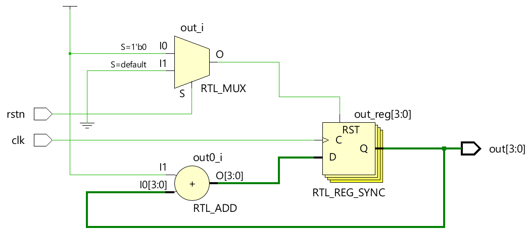
硬件示意图
<无脚本> Verilog