

研究乳液液滴尺寸和表面活性剂在基于界面不稳定性的胶束纳米晶体制造过程中的作用
摘要
界面不稳定性过程是一种新兴的通用方法,用于制造用于生物检测、成像和治疗的纳米晶体封装胶束(也称为胶束纳米晶体)。目前的工作利用荧光半导体纳米晶体(量子点或 QD)作为模型纳米晶体来研究基于界面不稳定性的纳米晶体封装胶束的制造过程。我们的实验结果表明,在 QD 封装的聚(苯乙烯-b-乙二醇)(PS-PEG)胶束的制造过程中,乳液液滴尺寸和表面活性剂聚(乙烯醇)(PVA)具有错综复杂的作用。当不使用PVA时,没有乳液滴,因此没有成功形成胶束;大尺寸 (~25 μm) 的乳液液滴会产生两种类型的 QD 封装胶束,其中一种是胶体稳定的 QD 封装的 PS-PEG 胶束,而另一种是胶体不稳定的 QD 封装的 PVA 胶束;相比之下,小尺寸(~3 μm 或更小)的乳液液滴只能产生胶体稳定的 QD 封装的 PS-PEG 胶束。这项工作获得的结果不仅有助于优化通过界面不稳定性方法制备的用于生物应用的纳米晶包封胶束的质量,而且还为特别是界面不稳定性过程和一般自组装提供了有用的新知识。
背景
应用纳米材料的潜力,例如荧光半导体纳米晶体(量子点,QD)[1,2,3]、超顺磁性氧化铁纳米粒子 (SPION) [4,5,6] 和金纳米粒子 [7,8,9]经过近 20 年的研究 [10, 11],用于生物医学检测、成像和治疗的方法已经成熟。因此,近年来,纳米生物材料研究的重点已从概念验证实验转向机理研究,旨在获得对纳米材料制造过程、纳米材料结构-性能关系以及纳米材料-生物系统相互作用的见解和系统理解。和转化研究,旨在确定和解决将纳米材料转化为工业和临床的关键问题。目前的工作重点是对胶束纳米晶体的一种新兴制备工艺,即界面不稳定性方法获得新的理解,胶束纳米晶体已成为一类主要的纳米生物材料。
在水中溶解疏水性纳米材料(例如,通过常用的基于有机溶剂的高温合成法合成的 QD、SPION 和金纳米粒子 [12,13,14])的主要策略是使用胶束包裹疏水性纳米材料。 15,16,17]。胶束是一种经典的自组装系统,其中两亲分子在水性环境中自发形成核壳结构(称为胶束),两亲分子的亲水链段朝外作为胶束壳,疏水链段面向向内作为胶束核,以最小化系统的总能量。胶束作为清洁剂和药物递送系统有着悠久的应用历史 [18,19,20,21,22],主要基于疏水分子(例如油,许多抗癌药物)可以封装到疏水核中的事实主要由疏水相互作用驱动的胶束 [23]。最近,胶束已被应用于封装单个纳米晶体(每个胶束封装单个纳米晶体)用于生物医学成像和检测 [24]。最近,相当多的研究小组报道了使用胶束封装多个纳米晶体,以实现胶束中不同纳米晶体之间的多功能性或协同效应 [25,26,27,28,29,30,31,32]。
一种新兴的制备胶束纳米晶体(纳米晶体封装胶束)的方法是界面不稳定性方法 [33,34,35]。 2008 年,Zhu 和 Hayward 首次报道了界面不稳定性过程,以制备氧化铁纳米颗粒封装的胶束 [33],后来被 Ruan 和 Winter 等人使用。 2010 年制备封装 QD 和 SPION 的胶束,2011 年制备封装不同荧光发射颜色的 QD 的胶束 [25, 26]。制备 QD 封装的聚(苯乙烯-b-乙二醇)(PS-PEG)胶束的界面不稳定性过程包括两个主要步骤:(1)水包油乳液液滴的形成。在该乳液中,油相包含疏水性量子点和溶解在非极性有机溶剂(本工作中为氯仿)中的两亲性嵌段共聚物 PS-PEG;水相含有溶解在水中的表面活性剂聚(乙烯醇)(PVA); (2) 纳米晶包裹胶束的形成。有机溶剂蒸发后,乳液的油/水界面变得不稳定,疏水相互作用驱动系统自发形成封装疏水量子点的 PS-PEG 胶束。实验中通常使用的成功形成胶束的一个简单指标是系统从乳状分散体(乳液)到透明分散体(胶束纳米晶体分散体)的戏剧性视觉转变,这要归功于纳米尺寸(典型直径为 30-40 nm ) 的胶束。在阮和温特之前利用界面不稳定性过程将量子点封装到 PS-PEG 胶束中的实验中发现,虽然这个过程具有许多积极的特征,但一个主要问题是在此过程中经常观察到系统的量子点荧光大量损失。制造/储存过程,以及荧光损失的原因是未知的。目前工作的目标有两个:一方面,我们旨在最大限度地减少由界面不稳定过程制备的 QD 封装的 PS-PEG 胶束的荧光损失;另一方面,通过技术优化过程,并利用量子点的荧光作为报道分子跟踪含量子点纳米复合材料的制备过程,我们旨在对新兴的纳米晶包封胶束的制备过程有新的认识。 ,即界面不稳定过程。我们的结果表明,乳液液滴尺寸和表面活性剂 PVA 在制造过程中起着关键作用:每个乳液液滴本质上都是一个“微反应器”,其中发生界面不稳定性和自组装“反应”,表面活性剂 PVA形成“微反应器”所需;除了胶体稳定的纳米晶体封装的 PS-PEG 胶束外,使用大的“微反应器”尺寸(~25 μm)会导致大部分胶体不稳定的纳米晶体封装的 PVA 胶束,同时使用小的“微反应器”尺寸(~ 3 μm 或更小,由超声或电喷雾产生)导致仅胶体稳定的纳米晶体封装 PS-PEG 胶束。
方法
材料
核壳 CdSe/ZnS 量子点(QD,发射波长 600 nm,覆盖有十八胺)购自 Ocean Nanotech。聚(苯乙烯-b-乙二醇)(PS-PEG)和羧酸封端的聚(苯乙烯-b-乙二醇)(PS-PEG-COOH)(PS 9.5 k Dalton,PEG 18.0 k Dalton)购自 Polymer Source .聚乙烯醇 (PVA)(分子量 13–23 kg/mol,87–89% 水解)购自 Sigma-Aldrich。 Tat肽(序列YGRKKRRQRRR)和RGD肽(Arg-Gly-Asp)购自ChinaPeptides。 1-乙基-3-(-3-二甲氨基丙基)碳二亚胺盐酸盐(EDC)和磺基-NHS购自Sigma-Aldrich。所有其他化学品均为试剂级。所有实验用水均经Millipore Milli-Q纯化系统二次蒸馏纯化。
通过界面不稳定性过程制备胶束纳米晶体
在典型的程序中,首先通过在有机溶剂氯仿中混合 QD(0.1 μM,0.1 ml)和 PS-PEG(10 mg/ml,20 μl)形成油相。然后加入水相(0.6 毫升水,含有 5 毫克/毫升 PVA)。通过手动摇动(用手剧烈摇动混合物 1 分钟)或超声处理(在 ShuMei KQ218 浴式超声仪中对混合物进行超声处理 30 秒)形成水包油乳液。在一些实验中,电喷雾用于生成超细乳液液滴,用于界面不稳定过程 [35]。使用不同的处理方法产生不同尺寸的乳液液滴以研究液滴尺寸的影响:~25 μm(直径)液滴通过手动摇动形成,~3 μm(直径)液滴通过超声处理形成,以及一些通过电喷雾形成数百纳米到几微米(直径)的液滴。将乳液用超纯水 (2.4 ml) 稀释四倍。将乳液置于化学通风橱中,以 100 rpm 的磁力搅拌使氯仿蒸发,从而形成胶束 QD。外观从乳状分散体到透明分散体的可见转变表明胶束形成成功。
当使用四氢呋喃 (THF) 作为有机溶剂时,首先通过在 THF 中混合 QD(0.1 μM,1 ml)和 PS-PEG(10 mg/ml,0.2 ml)形成油相。以逐滴方式(1 滴/20 秒)向溶液中加入去离子水,直至水含量达到 50% v /v .然后通过投票混合溶液 10-15 分钟,然后用去离子水透析 2 天以去除 THF(截留分子量 100,000 道尔顿)。
当使用电喷雾产生界面不稳定过程的液滴时,操作如下[35]。使用同轴电喷雾配置。内毛细管针为 27 号(外径 500 微米;内径 300 微米)不锈钢毛细管,外针为 20 号(外径 1000 微米;内径 500 微米)不锈钢三通接头。喷嘴尖端位于接地钢环上方 0.8 厘米和玻璃收集盘上方 10 厘米。通过混合 QD 和 PS-PEG 形成油相,然后使用注射泵(SPLab01,深圳,中国)以 0.6 毫升/小时的流速输送到内部不锈钢毛细管。油相中 PS-PEG 和 QD 的浓度分别为 5 mg/ml 和 0.2 μM。通过将 PVA 以 40 mg/ml 溶解在去离子水中来制备水相。使用第二个注射泵(SPLab01,深圳,中国)以 1.5ml/h 的流速将水溶液输送到同轴针头的外环。通常在 6-7 kV 范围内的电压下,在同轴喷嘴的尖端观察到凹锥射流(泰勒锥)。将含有 10 毫升去离子水的玻璃收集盘放置在喷嘴尖端下方以收集液滴。电喷雾时间(在形成稳定的泰勒锥之后)通常为 30-90 分钟。随后在化学通风橱中进一步蒸发过夜。最后,将玻璃收集皿中的分散液转移到15 ml离心管中进行表征。
胶束量子点物理特性的表征
胶束量子点的形态通过透射电子显微镜 (TEM, JEOL JEM-2100 (HR)) 表征,并且在本工作中通过 TEM 研究的所有样品都被 1% 的磷钨酸 (PTA) 负染色。粒度通过 TEM 或动态光散射 (DLS) 表征。荧光光谱由日立F-4600荧光分光光度计测得。
纳米材料的细胞毒性
对三种充分表征的人类癌细胞系进行了细胞毒性研究,即 A549(肺泡基底上皮)、MCF-7(乳房)和 HeLa(宫颈)细胞(购自 KeyGen Biotech,中国)。在潮湿的培养箱(37°C 和 5% CO 2 )中用含有 10% 胎牛血清和抗生素(青霉素/链霉素)的培养 DMEM 维持细胞。对于细胞毒性评估,将细胞接种到 96 孔板中的 200 μl 培养基中 24 小时。然后,将细胞与不同浓度的胶束 QD 在新鲜培养基中在 37°C 和 5% CO2 气氛中孵育。孵育 24 小时后,去除具有分散胶束 QD 的培养基,并根据制造商的方案进行 MTT 测定。最后,在微量滴定板读数器中在 570 nm 处测量每个孔中的吸光度。
QD 封装的 PS-PEG-COOH 胶束与肽的结合
PS-PEG-COOH 胶束是用上述界面不稳定性程序制备的,使用 PS-PEG-COOH 分子代替 PS-PEG 分子。然后通过 EDC/磺基-NHS 方法进行与 Tat 肽或 RGD 肽的缀合。为了激活胶束的羧基,将 0.3 毫升含有 2 毫克/毫升 EDC 和 5 毫克/毫升磺基-NHS 的 0.3 毫升 MES 缓冲溶液添加到胶束分散体 (3 毫升) 中,并在室温下反应 30 分钟而不搅拌.然后通过使用 30-kD 超滤管(以 10 krpm 离心 5 分钟)去除额外的 EDC 和磺基-NHS,并将获得的分散体重新悬浮在 PBS(1 ml)中。随后,加入 50 μl Tat 肽(PBS 中 2 mg/ml)或 50 μl RGD 肽(PBS 中 0.5 mg/ml)并分别在 4°C 下反应 12 小时。获得的肽缀合的 PS-PEG 胶束 QD 分散体通过使用 50-kD 超滤管(10 krpm 离心 5 分钟)纯化 3 次以去除多余的肽分子并重新悬浮在 PBS (1 ml) 中。
活细胞成像
活细胞成像用于研究 Tat 肽偶联的 PS-PEG 胶束量子点的细胞内化和细胞内转运。 HeLa细胞(购自KeyGen Biotech,China)以初始融合度为20%(接种密度1 × 10 5 )接种于玻璃底组织培养板上 细胞/毫升)在 600 μl 培养基(DMEM + 10% 胎牛血清)中,并在 37°C 下在 5% CO2 中培养 40 小时。然后添加 Tat 肽缀合的 PS-PEG 胶束 QD(细胞培养基中的 10 nM QD)。与胶束 QD 孵育 1 小时后,将细胞用新鲜培养基洗涤两次以去除游离的胶束 QD(进行洗涤步骤是为了使内化胶束 QD 的细胞内转运开始时间大致为添加的所有纳米粒子都相同)。 6 小时后,每块细胞通过活细胞成像系统成像,该系统由细胞培养室(IX3W,Tokai Hit)、落射荧光显微镜(IX-83,Olympus,卤素灯作为光源)组成)、旋转圆盘共焦系统 (Andor) 和电子倍增电荷耦合器件 (EMCCD) 相机(Evolve 512,Photometrics)。此处使用的活细胞共聚焦成像系统允许对显微镜载物台上培养的活细胞进行转盘共聚焦成像,这对于研究细胞运输过程特别有用。通过在显微镜载物台上培养活细胞,可以确保以最小的干扰监测自然生物过程。为了对细胞核进行复染,就在成像之前(在细胞运输的特定时间点),将荧光染料 Hoechst 33342(在细胞培养基中为 5 μM)与活细胞孵育 20 分钟。
活细胞成像还用于研究 RGD 肽偶联的 PS-PEG 胶束量子点与 α v 的特异性结合 β3-整联蛋白分子,使用 α v β3-integrin 过表达细胞系(U87 MG 细胞,购自 KeyGen Biotech,China)与不含 α v 的细胞系 β3-integrin 过表达(MCF-7 细胞,购自 KeyGen Biotech,China)。采用上述Tat肽偶联PS-PEG胶束QD的细胞成像方案,主要修改为RGD肽偶联胶束QD的浓度为100 nM(细胞培养基中的QD)。
结果与讨论
我们和其他人最近引入了界面不稳定性方法来封装纳米晶体以形成用于生物应用的复合纳米粒子。然而,我们经常遇到关于量子点荧光强度的不可重复且有时相互矛盾的结果(此处使用量子点作为纳米晶体的模型)。这个问题需要解决以转化为工业和临床。整个制造过程中涉及的许多因素(例如,溶剂、聚合物、温度、“微反应器”尺寸)都可能导致荧光损失和不可重复的结果。我们调查了涉及的各种因素,发现“微反应器”(乳液液滴)尺寸是这方面的关键因素,表面活性剂 PVA 的使用是一个密切相关的因素。下面,我们主要描述乳液液滴尺寸以及表面活性剂PVA的影响结果。
我们比较了两种不同机械强度的乳化方法的效果,即手动摇动(手动剧烈摇动混合物)和浴超声处理(在浴超声仪中对混合物进行超声处理)。我们发现这两种方法最终都可以在有机溶剂蒸发后产生透明和均匀的分散体,表明纳米晶体包裹的胶束成功形成(图 1b,c,底部)。由于透明和均匀的视觉外观通常用作基于界面不稳定性的制造过程中胶束成功形成的简单方便的指标,因此以前忽略了不同乳化方法对胶束产品的潜在影响。我们分别使用光学显微镜检查了这两种不同乳化方法产生的乳液液滴的大小,发现手动摇动方法产生了 ~25 μm(直径)的液滴,而水浴超声法产生了 ~3 μm(直径)(图 1b、c、顶部)。使用光学显微镜图像测量每个样品的大约 500 个液滴的尺寸以获得平均尺寸和尺寸分布。统计分析(学生的t 测试)表明手动摇动(~25 μm)和超声(~3 μm)形成的液滴平均尺寸之间的差异具有统计学意义(P <0.001)。重要的是,我们还进行了对照实验以确认这两种不同的乳化方法分别在上述两个不同尺寸范围内一致地产生乳液液滴尺寸:手动摇动几个不同的持续时间(0.5、1、2 和 3 分钟)都导致在 ~25 μm 乳液液滴(具有相似的尺寸分布)和几个不同持续时间(0.5、1 和 2 分钟)的水浴超声处理中均产生 ~3 μm 乳液液滴(具有相似的尺寸分布,附加文件 1:图 S1) .
<图片>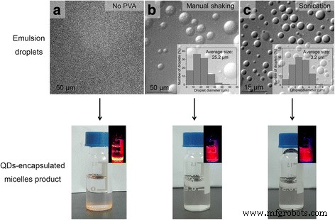
在有机溶剂蒸发后,肉眼观察乳液液滴和产生的 QD 封装的胶束。 一 没有使用 PVA。几乎没有形成乳滴(顶部图像 );去除有机溶剂后几乎没有形成 QD 封装的胶束(底部图像 ,插图 使用手持式紫外灯激发红色显示相应的荧光图像 量子点荧光)。 b 手动摇动用于形成乳液液滴。形成了约 25 μm 的乳液液滴(顶部图像 ,插图 显示了来自 500 个液滴的图像分析的液滴尺寸测量结果)。此外,发现由于不同摇动时间导致的尺寸变化最小(图 S1)。去除有机溶剂后,形成透明且均匀的分散体,表明纳米晶封装的胶束成功形成(底部图像 ,插图 使用手持式紫外灯激发红色显示相应的荧光图像 量子点荧光)。 c 浴超声用于形成乳液液滴。形成了约 3 μm 的乳液液滴(顶部图像 ,插图 显示了来自 500 个液滴的图像分析的液滴尺寸测量结果)。此外,发现由于不同摇动时间导致的尺寸变化最小(图 S1)。去除有机溶剂后,形成透明且均匀的分散体,表明纳米晶封装的胶束成功形成(底部图像 ,插图 使用手持式紫外灯激发红色显示相应的荧光图像 量子点荧光)。为了分析特定样品的乳液液滴的尺寸,首先拍摄乳液液滴的光学显微镜图像,然后通过免费软件 ImageJ 测量~500 个液滴的直径以获得平均尺寸和尺寸分布样品的乳化液滴
此外,我们还在没有表面活性剂 PVA 的情况下进行了乳化处理,发现从光学显微镜结果(图 1a,顶部)来看,几乎没有成功形成乳液液滴,并且实际上,没有成功形成胶束,从在最终产品中观察到几乎完全的相分离(QD 沉淀),即未能形成胶束产品(图 1a,底部)。图 1a 的结果表明,表面活性剂 PVA 在成功形成乳液液滴(作为“微反应器”)和胶束(作为最终产品)的界面不稳定过程中是必需的。这很重要,因为它表明,虽然 PS-PEG 本质上也是两亲性的,但系统中单独存在 PS-PEG(不存在 PVA)不能提供界面不稳定过程所需的乳液液滴。
尽管产品分散体在形成后似乎是透明和均匀的(TEM 和 DLS 表征结果显示球形和单分散 QD 封装的胶束,附加文件 2:图 S2),但上述两种不同的乳液液滴尺寸的差异发现乳化方法,即手动摇动和超声处理导致胶束纳米晶体产品的很大差异。我们分别测量并跟踪了通过手动摇动和超声处理形成的胶束 QD(QD 封装胶束)在 4°C 下 40 天的荧光强度变化。我们发现,对于胶束,虽然在胶束形成过程中荧光强度(通过荧光光谱测量)保持不变,但随着时间的推移(~10天)胶束 QD 的荧光强度逐渐降低到仅原始荧光强度水平的 50% 左右,之后保持稳定(图 2a)。相比之下,通过超声处理形成的胶束 QD(30 秒,由~3 μm 乳液液滴形成)在整个时间段内很大程度上保持了荧光强度(通过荧光光谱测量)(图 2a)。此外,在样品在 4°C 下静置 10 天后,我们分别用肉眼观察了通过手动振荡和超声处理形成的胶束 QD 分散体的底部。在胶束的底部,储存 10 天后通过手动摇动(1 分钟)形成 QD 分散体,肉眼观察到可见的沉淀物(图 2a,插图)。相比之下,在储存 10 天后通过超声处理(30 秒)形成的胶束 QD 分散体的底部,肉眼没有观察到可见的沉淀物(图 2a,插图)。这些结果表明,虽然两种乳化方法都可以成功形成具有相似封装效率的 QD 封装胶束,但大部分 QD 封装胶束由较大的乳液液滴(~25 μm,通过手动摇动 1 分钟产生)形成) 是胶体不稳定的,随着时间的推移导致沉淀,从而导致分散体的荧光损失,而所有由较小的乳液液滴(~3 μm,由浴超声处理 30 秒产生)形成的 QD 封装胶束都是胶体稳定的,因此保持不变长时间的荧光(储存 10 天后分散体的 TEM 研究也显示胶束纳米晶体的形态保持良好,如附加文件 3:图 S3 所示)。此外,我们发现,当超声处理时间从 30 秒增加到 1 和 2 分钟以形成乳液液滴时,荧光强度急剧降低,尽管 QD 封装的胶束在不同的时间段内胶体稳定根据整个储存时间的稳定荧光强度判断超声处理持续时间(图 2b)。图 2b 中显示的荧光损失可能是由于强而长时间的机械处理在 QD 上产生表面缺陷造成的。在对照实验中,还发现溶解在氯仿中的疏水 QD 的荧光强度在超声处理下随着超声时间的增加逐渐降低(附加文件 4:图 S4),这支持了荧光损失的这一提议原因。总之,图 2a、b 揭示了由界面不稳定过程制造的 QD 封装胶束系统中荧光损失的两种主要机制,即胶体不稳定的 QD 封装胶束和机械处理产生的 QD 表面缺陷。
<图片>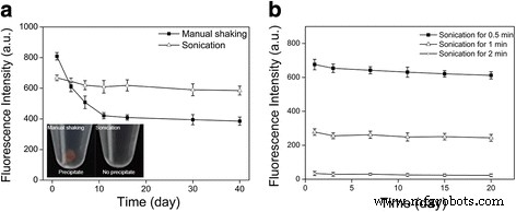
通过界面不稳定性过程制造的 QD 封装胶束的荧光稳定性。 一 QD 封装胶束的荧光强度(通过荧光光谱法测量)随时间的变化,通过手动摇动(1 分钟,即 ~25 μm 液滴)或超声处理(30 秒,即 ~3 μm 液滴),分别。 插图 是 QD 封装的胶束分散体在 4°C 下储存 10 天后的图像,其中乳液液滴通过手动摇动(1 分钟,即 ~25 μm 液滴)或超声处理(30 秒,即 ~3 μm 液滴),分别。面板a 表明 QD 封装胶束的荧光损失的一个原因是胶体不稳定的 QD 封装胶束的存在。 b QD 封装胶束的荧光强度(通过荧光光谱法测量)随时间的变化,具有通过超声处理形成的乳液液滴(即,~3 μm 液滴),持续三个不同的超声处理持续时间。面板 b 表明 QD 封装胶束荧光损失的原因之一是强和长时间机械处理产生的 QD 表面缺陷
在这两种荧光损失机制中,虽然众所周知,QD 荧光损失可能是由于 QD 表面的损伤引起的,但部分胶束胶体不稳定的结果却出乎我们的意料。因此,我们对这一特定机制进行了进一步研究。我们首先提出了上述沉淀量子点是否确实被封装在胶束(或胶束状组装结构)中的问题。我们发现,简单地摇动带有这些沉淀物的分散体可以导致分散体的荧光强度恢复到原始水平(图 3a,左);相比之下,对在水中沉淀的疏水 QD 使用相同处理的对照研究显示荧光强度没有这种增加(图 3a,右)。此外,储存 10 天后通过手动摇动形成的产品样品底部的透射电子显微镜 (TEM) 图像显示大量 QD 聚集在大型球形和非球形结构中(图 3b,左);相比之下,在储存 10 天后通过超声处理形成的产品样品的底部,相应的 TEM 图像仅显示少量聚集在球形结构中的 QD(图 3b,中间)。因此,这些结果表明沉淀的量子点确实被包裹在胶束或胶束状组装结构中,即这些量子点不是裸露的疏水量子点。然后我们问了这些胶体不稳定胶束(或胶束状组装结构)的化学性质是什么。因为 PS-PEG 胶束应该是胶体稳定的,我们假设不稳定的胶束(或胶束状组装结构)是由表面活性剂 PVA 形成的。这一假设得到以下两条实验证据的支持。首先,我们发现在界面不稳定过程中使用不含 PS-PEG 的 PVA 确实会导致胶束包裹 QD(图 3b,右)。其次,我们分别对 PS-PEG 胶束 QD 和 PVA 胶束 QD 进行了透析实验,以进行比较。对纯水进行透析处理后(透析袋的截留分子量为 200 kD,大于 PVA 和 PS-PEG 的分子量),PS-PEG 胶束 QD 保持胶体稳定,从以下事实判断QD 荧光在分散体中保持均匀(图 3c,左)。形成鲜明对比的是,在与上述几乎相同的透析处理后,PVA 胶束 QD 分散体导致清晰可见的荧光聚集体(图 3c,右)。 As the dialysis experiment could be considered as mimicking the dilution treatment that micelle-based nanomaterials would encounter once introduced to an in vivo environment, our dialysis experimental results indicate that the QD-encapsulated PVA micelles would become colloidally unstable in vivo. Therefore, the results shown in Fig. 3c suggest that the fluorescence loss from using large emulsion droplets (~25 μm, produced by manual shaking) is caused by colloidally unstable PVA micelles (or other micelle-like assembly structures) encapsulating QDs.

Examining the colloidally unstable part of the micellar QDs. 一 Left , the disappearance of fluorescence of the colloidally unstable part of the micellar QDs from the dispersion after 10-day storage could be resumed after the dispersion was shaken. Right , the fluorescence of hydrophobic QDs was not detected in water because they could not be dispersed in water. b Left and middle are the TEM images of the bottom portions of the micellar QD dispersions formed from manual shaking for 1 min (i.e., ~25 μm emulsion droplets) and sonication for 30 s (~3 μm emulsion droplets), respectively, after 10-day storage. Right , TEM image of PVA micellar QDs. c Dialysis (against water) treatment on PS-PEG micellar QDs (left ) and PVA micellar QDs (right ), respectively. A hand-held UV lamp was used to excite the red QD fluorescence
Further, we conducted two additional experiments to confirm the roles of emulsion droplet size and the surfactant PVA. In the first experiment, we used a water-miscible organic solvent tetrahydrofuran (THF) instead of the water immiscible organic solvent chloroform. In this case, the “emulsion droplet” size could be considered as zero, and the surfactant PVA was not used because it was not needed to facilitate the mixing of oil phase with water phase. It was found that the fabrication process produced QD-encapsulated micelles with stable fluorescence (Fig. 4a), which is consistent with the result that small emulsion droplets lead to colloidally stable QD-encapsulated micelles and stable fluorescence. In addition, it was observed that the micelles formed by this process (with THF, without PVA) had large size distribution and some of the formed micelles even had non-spherical shapes (Fig. 4b). This indicates that “zero droplet size” could lead to poorly controlled micelle size and shape (although the formed micelles are colloidally stable). Thus, the results of the “zero emulsion droplet size” experiment (with the water-miscible THF as the organic solvent), on the one hand, are consistent with the finding that smaller emulsion droplets lead to colloidally stable micellar nanocrystals (judging by the stable fluorescence given by “zero-sized emulsion droplets”), and on the other hand, indicate the advantage of having an emulsion droplet (with non-zero droplet size) compared with no emulsion droplet at all (“zero-droplet size”, which gives poor micelle morphology). In the second experiment, we used electrospray, which is known to give ultrafine and uniform droplets with the typical droplet size range being a few hundred nanometers to a few micrometers (smaller than what the sonication treatment generates), as the method to produce emulsion droplets (PVA was used in this case) [35,36,37,38,39]. It was found that this method led to micellar QDs with stable fluorescence and well-controlled micelle size and shape (Fig. 4c, d). It should be mentioned that electrospray typically can only produce droplet sizes smaller than what the sonication treatment gives (i.e., a few hundred nanometers to a few micrometers). Thus, to study the effect of larger emulsion droplet size, in this work, we used another mechanical treatment method, i.e., manual shaking, to give larger droplets (~25 μm). The actual size of electrospray-generated droplets is difficult to be obtained by direct imaging (for example, the size of electrospray-generated oil-in-water emulsion droplets would change greatly upon entering the large volume of water phase in the collection container due to aggregation and fusion, and the typical sub-micrometer size of electrospray-generated droplets is approaching the diffraction limit of optical microscopy), but could be theoretically calculated or experimentally measured by methods that characterize aerodynamic mobility as done previously in the literature.

Using additional methods to form small emulsion droplets to confirm the importance of droplet size. 一 , b Using water-miscible THF as the oil phase solvent (without using PVA) led to micellar QDs with stable fluorescence (a ) and irregular micelle shapes (b )。 c , d Using electrospray (with PVA) to form droplets led to micellar QDs with stable fluorescence (c ) and regular micelle shape (d )
Figure 5 presents a schematic to summarize our results and insights on the roles of emulsion droplets and the surfactant PVA in the interfacial instability-based fabrication process of nanocrystals-encapsulated micelles (with QDs as the model for nanocrystals). Each oil-in-water emulsion droplet serves as a “micro-reactor” for the interfacial instability-mediated self-assembly “reaction.” When no PVA (surfactant) is used, emulsion droplet does not form, and thus, no micelle is formed. When the emulsion droplet is large in size (~25 μm), only a part of the QDs (approximately 50%, based on the remaining fluorescence intensity in the dispersion after 10-day storage, Fig. 2a) in the droplet get encapsulated in PS-PEG (an amphiphilic block copolymer) micelles, which are colloidally stable, while the other part of the QDs get encapsulated in PVA (also an amphiphilic polymer, but not a block copolymer) micelles, which are colloidally unstable. When the emulsion droplet is small in size (~3 μm or smaller), nearly all QDs (based on the remaining fluorescence intensity in the dispersion after 10-day storage, combined with comparison of fluorescent intensity with hydrophobic QDs undergoing similar mechanical treatment, Fig. 2a, Fig. 4a, c, and Additional file 4:Fig. S4) in the droplet get encapsulated in stable PS-PEG micelles. Thus, the roles of emulsion droplets and the surfactant PVA in the interfacial instability-based fabrication process of nanocrystal-encapsulated micelles are intricate and intertwined, particularly in the context of biological applications:the surfactant PVA is required for successful formation of emulsion droplets and micelle products, and yet it is also responsible for formation of the colloidally unstable part of nanocrystal-encapsulated micelles, which would be detrimental in a number of biological applications; and the key to avoid the colloidally unstable nanocrystal-encapsulated PVA micelles is to use emulsion droplets small in size (~3 μm or smaller).

Roles of emulsion droplet size and surfactant in the interfacial instability-based fabrication of micellar nanocrystals
In addition, it should be mentioned that, for a well-dispersed oil-in-water emulsion to form, a surfactant is often required to lower the surface tension between the oil phase and water phase, and PVA was selected here as the surfactant because it was applied in nearly all the previous works on using the interfacial instability method to fabricate micelles [25, 26, 33,34,35]. We cannot rule out the possibility that other surfactants could give different results. Examining the effects of different types of surfactant would be part of the future studies.
Finally, we performed proof-of-concept biological experiments using live cells to demonstrate that our micellar nanocrystal products (with the emulsion droplets formed from sonication treatment for 30 s) are (1) fairly biocompatible, (2) can be functionalized with biological molecules, (3) can be introduced into live cells, and (4) if conjugated with biological targeting molecules, can bind with specific biological targets (Fig. 6). Cytotoxicity studies by MTT assay showed that the QD-encapsulated PS-PEG micelles had fairly low cytotoxicity in three different cell lines compared with the negative control (cultured cells in the absence of nanomaterials added, i.e., concentration being zero) (Fig. 6a). To bio-functionalize QD-encapsulated PS-PEG micelles, in the micelle fabrication process the PS-PEG molecules were replaced with PS-PEG-COOH molecules, the latter of which could then be conjugated with a wide spectrum of biomolecules (e.g., peptides, nucleic acids, and antibodies) via well-established bioconjugation methods. To show that QD-encapsulated PS-PEG micelles can be introduced into live cells, the micelles were conjugated with Tat peptide, which is derived from HIV virus and is known to be able to introduce a variety of nanomaterials into live cells with high efficiency and low toxicity [40,41,42]. The thus-formed Tat peptide-conjugated PS-PEG micellar QDs were then incubated with HeLa cells, and live cell confocal imaging was conducted to study the cellular transport of the fluorescent nanomaterials. The live cell confocal imaging system used here permits spinning-disk confocal imaging of live cells cultured on the microscope stage, ensuring that the natural transport process is followed with minimal disturbance. HeLa cells were selected here because this cell line was used in the first tracking study of the cellular transport of Tat peptide-conjugated QDs by Ruan et al. [42]. It was found that, 6 h after the first contact of Tat peptide-conjugated PS-PEG micellar QDs with the cells, many of the Tat peptide-conjugated PS-PEG micellar QDs had been internalized by the cells, judging by the composite confocal images to show the positions of QDs, cell nucleus and cell periphery, and the cellular uptake level was much higher than that without the assistance of Tat peptide (Fig. 6b). Imaging of the change of QD distribution at different time points of cellular transport for the Tat peptide-conjugated PS-PEG micellar QDs indicated that, after entering the cells, they were gradually accumulated at a perinuclear region (Additional file 5:Fig. S5). Additional file 6:video 1 shows a three-dimensional reconstructured image of the distribution of Tat peptide-conjugated PS-PEG micellar QDs in the cell at the time point of 24 h, which further confirms cellular internalization and perinuclear accumulation. The behavior of the cellular transport of Tat peptide-conjugated PS-PEG micellar QDs is consistent with that of Tat peptide-conjugated QDs previously reported in the literature [42]. Further, to show that QD-encapsulated PS-PEG micelles can be modified (bio-functionalized) to bind with specific biological targets via ligand-receptor binding, the micelles were conjugated with RGD peptide, which is known to specifically recognize integrins on cell surface [43]. Fluorescent microscopy imaging results indicated that RGD peptide-conjugated PS-PEG micellar QDs could bind with α v β3-integrin over-expressed cells (U87MG cell line, a human glioblastoma cell line, Fig. 6c, right), judging by the significant QD fluorescence on or in the cells. In contrast, the two control experiments, one of which used RGD peptide-conjugated PS-PEG micellar QDs to incubate with MCF cells (without α v β3-integrin over-expression, Fig. 6c, left) and the other of which used PS-PEG-COOH micellar QDs (without RGD peptide conjugation) to incubate with U87MG cells (Fig. 6c, middle), showed little to no QD fluorescence on or in the cells. Thus, these results demonstrated the ability of RGD peptide-conjugated PS-PEG micellar QDs to specifically bind with α v β3-integrin molecules.

Interactions of PS-PEG micellar QDs (prepared by using sonication 30 s in the interfacial instability method) with biological cells. 一 PS-PEG micellar QDs were fairly biocompatible judging from the MTT cytotoxicity assay results. The concentrations were based on the amounts of QDs used. b Tat peptide-conjugated PS-PEG micellar QDs can be internalized by live cells. c RGD peptide-conjugated PS-PEG micellar QDs can specifically recognize and bind with the α v β3-integrin molecules over-expressed on U87MG cells (right image )。 In comparison, in the absence of α v β3-integrin over-expression (MCF-7 cells, left image ) or Tat peptide (PS-PEG-COOH micellar QDs, middle image ), no significant binding (QD fluorescence) was observed. The red fluorescence was from QDs. The cell nucleus was stained by the blue fluorescent dye Hoechst 33342. Cell periphery is shown by white line (from the corresponding bright field microscopy images)
Conclusions
In conclusion, we have used QDs as the model nanocrystals to follow the interfacial instability process, an emerging general method to fabricate nanocrystal-encapsulated micelles. Our results reveal the key roles of emulsion droplet size and the surfactant PVA in the interfacial instability process. These results not only help to optimize the quality of nanocrystal-encapsulated micelles for biological applications such as biological detection, imaging and therapy, but offer helpful new knowledge on the interfacial instability process in particular and self-assembly in general.
缩写
- EDC:
-
1-Ethyl-3-(-3-dimethylaminopropyl) carbodiimide hydrochloride
- PS-PEG:
-
Poly (styrene-b-ethylene glycol)
- PS-PEG-COOH:
-
Carboxylic acid terminated poly (styrene-b-ethylene glycol)
- PTA:
-
Phosphotungstic acid
- PVA:
-
Poly (vinyl alcohol)
- QD:
-
Quantum dot
- SPION:
-
Superparamagnetic iron oxide nanoparticle
- TEM:
-
Transmission electron microscopy
- THF:
-
Tetrahydrofuran
纳米材料