

控制直流电机的技巧
组件和用品
 |
| × | 1 | |||
| × | 1 | ||||
 |
| × | 4 | |||
 |
| × | 4 | |||
 |
| × | 4 | |||
| × | 1 | ||||
 |
| × | 1 | |||
| × | 1 | ||||
 |
| × | 1 | |||
 |
| × | 1 |
应用和在线服务
 |
|
关于这个项目
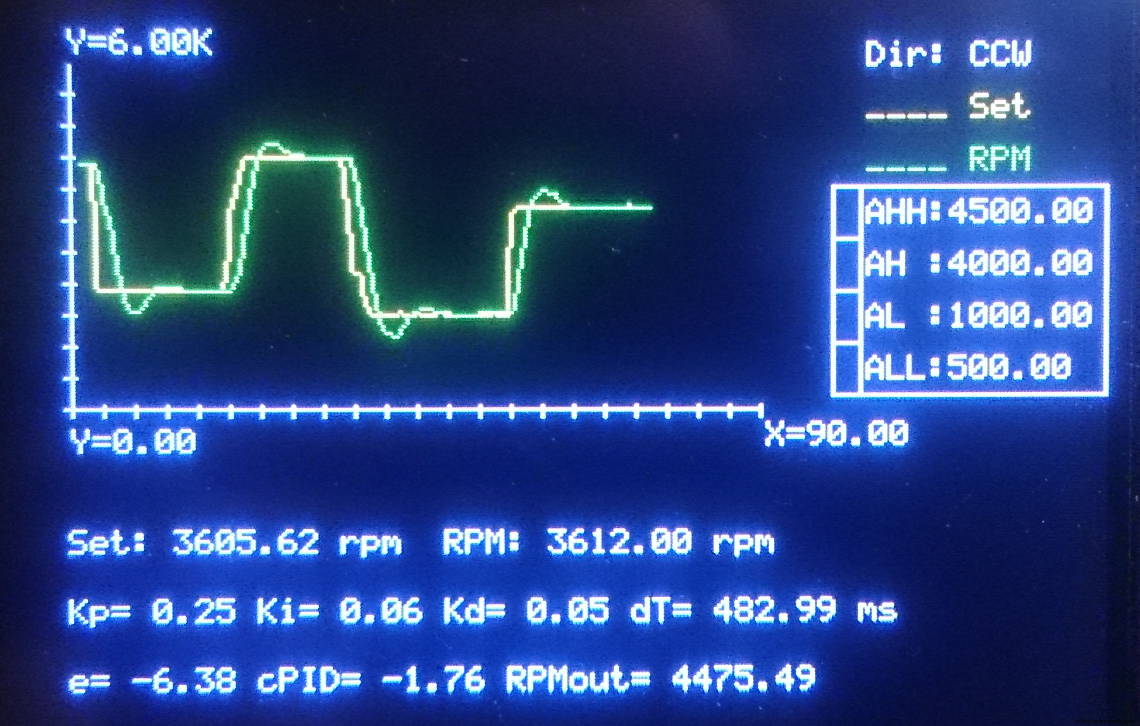
通过 PID 控制器和 PWM 输出控制直流电机的速度和方向
介绍
几乎在所有可用项目中,发起人都希望一起控制电机速度和方向,但他们更喜欢直接将 PWM 发送到直流电机,甚至通过电机控制电路。但是如果你需要完全匹配你想要的速度,这种方法总是失败,因为被称为“摩擦”和“惯性”的孪生兄弟。
(请不要责怪双胞胎。无论何时何地你想采取一些有或没有的行动,双胞胎都会立即来采取行动,只是为了帮助你控制一切。而惯性让事情在采取行动之前“思考”,摩擦限制了他们的加速度和速度。如果没有完全控制,“力量”就是“虚无”。)
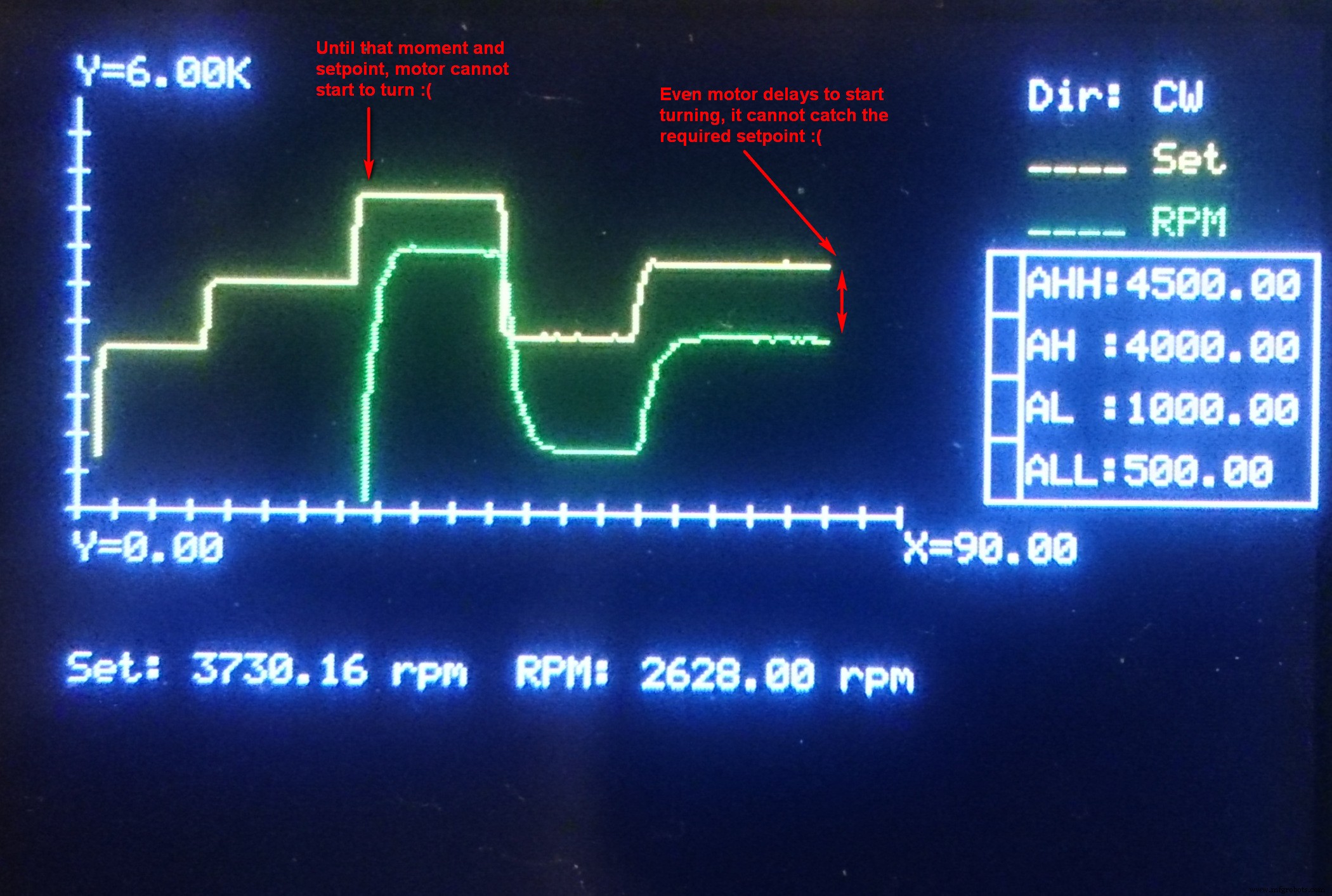
因此,如果您尝试通过将输入作为 PWM 信号发送到输出来直接控制电机的速度,实际速度将永远不会满足您的设定点,并且会有显着差异(误差),如上图所示。这里我们需要另一种方式,叫做“PID控制”。
PID 控制器
什么是PID控制?想象一下如何驾驶您的汽车:要从完全停止开始行驶,您必须比正常巡航时更多地踩下油门。在以(几乎)恒定速度行驶期间,您无需过多踩下油门踏板,只需在需要时恢复速度损失即可。此外,如果加速度高于您的需要,您可以稍微松开它。这也是“高效驾驶”之道。
因此,PID 控制器的作用完全相同:控制器读取设定点和实际输出之间的差异“错误信号 (e)”。它有 3 个不同的组成部分,称为“比例”、“积分”和“微分”;所以控制器的名字出现在每个字母的第一个字母之后。比例分量简单地定义了控制器输出相对于实际误差信号的斜率(加速度)。积分部分及时对误差信号求和,以最小化最终误差。微分元件观察误差信号的加速度,并进行“调整”。在此不再赘述,有兴趣的请自行上网搜索。
在我的 Arduino 程序中,PID 控制器被编写为如下所示的函数:
float controllerPID(float _E, float _Eprev, float _dT, float _Kp, float _Ki, float _Kd){ float P, I, D; /* 基本公式:U =_Kp * ( _E + 0.5*(1/_Ki)*(_E+_Eprev)*_dT + _Kd*(_E-_Eprev)/_dT ); */ P =_Kp * _E; /* 比例分量 */ I =_Kp * 0.5 * _Ki * (_E+_Eprev) * _dT; /* 积分分量 */ D =_Kp * _Kd * (_E-_Eprev) / _dT; /* 导数 */ 返回 (P+I+D);} 然后简单地通过将当前输出值和PID控制器的输出相加来确定最终输出值。以下是主程序的以下部分以及误差信号和PID控制器输出的计算:
/* 电机的错误信号、PID 控制器输出和最终输出 (PWM) */E =RPMset - RPM;float cPID =controllerPID(E, Eprev, dT, Kp, Ki, Kd);if ( RPMset ==0 ) OutputRPM =0;否则 OutputRPM =OutputRPM + cPID;如果(输出RPM <_minRPM)输出RPM =_minRPM; 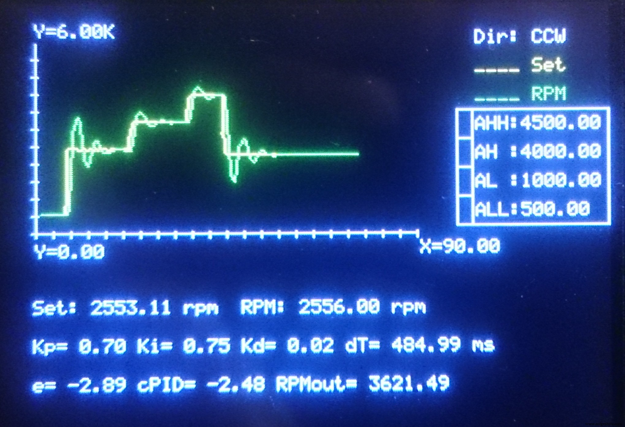
直流电机供电电路
当然,从不建议直接从 Arduino 或类似控制板的输出驱动直流电机。与控制器卡的输出无法提供的电流相比,直流电机需要大量电流。所以你需要驱动继电器线圈。但这里又出现了另一个问题:继电器有机械部件,它们可能会在中长期出现故障。我们这里需要另一个组件,晶体管。
实际上直流电机是由电流驱动的,而不是由电压驱动的。所以通过使用这个原理,我决定使用晶体管。但是您必须选择能够承受电机电流的正确晶体管。首先,通过连接电源直接运行电机,并在最大工作条件下测量电流,或参考制造商的规格。
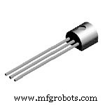
这样做之后,我决定在“桥”上使用四个 BC307A PNP 双极结晶体管来确定通过电机线圈的电流方向(实际上,由于能够承受更高的集电极电流,NPN BC337 组会更好地工作,但我没有当时没有它们)。
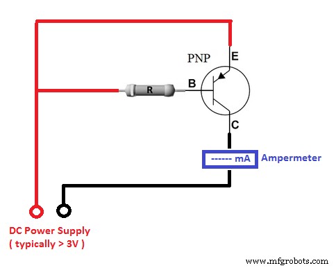
由于电机电流应通过晶体管的发射极-集电极路径,因此必须使用具有大致相同直流电流增益 (hfe) 系数的晶体管。要检查它,您可以使用以下电路,并收集晶体管,在安培计上提供大致相同的电流读数。要设计这些初步电路,您需要考虑以下几点:
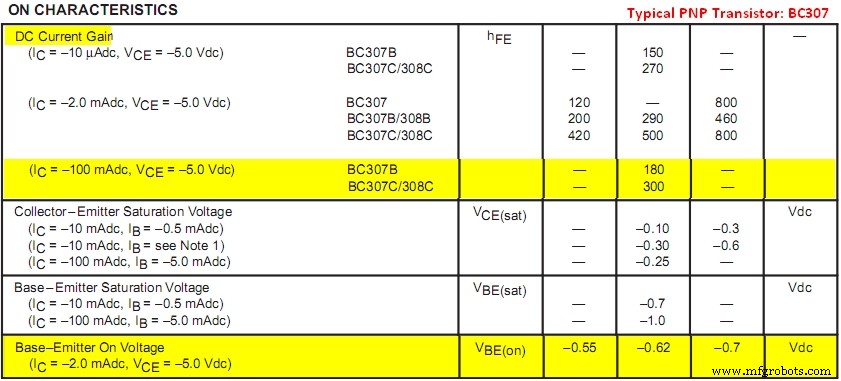
- 找到“基极发射极电压 ” (VBEon ) 的晶体管。它是施加到基极以开启晶体管的最小电压。
- 找出典型的“直流电流增益 ” (hfe ) 的晶体管在集电极电流附近接近电机电流。通常是集电极电流之间的比率 (IC ) 和基本电流 (IB ), hfe =IC / IB .
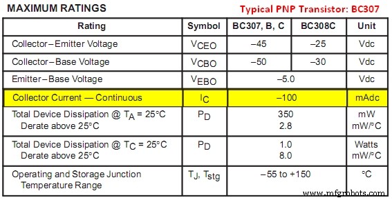
- 找到“最大连续收集器电流 ”的晶体管 (ICmax )。电机的直流电流绝对值绝对不能超过这个值。我可以使用 BC307,因为我使用的电机需要 70 mA,而晶体管的 ICmax(abs) =100 mA。
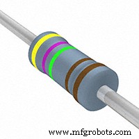
现在你可以确定接Base的电阻值了:首先,你要考虑你的控制卡输出的限制,并尽量保持Base电流尽可能小(所以建议选择晶体管的DC Current Gain为最大尽可能将控制器板上输出的额定电压作为“触发电压 ” (VT ),并找到所需的基极电流 (IBreq ) 除以电机电流 (IM ) 到直流电流增益 (hfe ) 晶体管:IBreq =IM / hfe .
然后确定要在电阻器上下降的电压 (VR ),减去基极-发射极导通电压 (VBEon ) 来自触发电压 :VR =VT - VBEon .
最后将电压分压到 电阻器 (虚拟现实 ) 到所需的基本电流 (IBreq ) 找到电阻值 (R ):R =VR / IBreq .
[组合公式:R =(VT - VBEon) * hfe / IM ]
在我的情况下:
- 电机电流:IM =70 mA
- BC307A 参数:ICmax =100 mA,hfe =140(我测得大约),VBEon =0.62 V
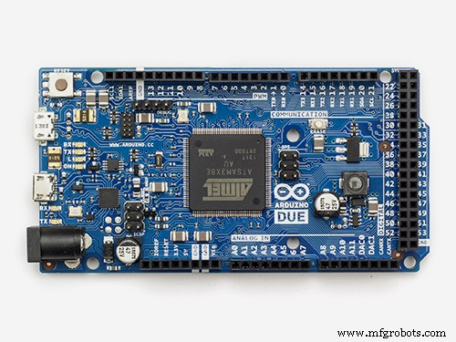
- 触发电压:VT =3.3 V(Arduino Due 的 PWM 输出)
- R =5360 ohm(因此我决定使用 2K2 和 2K7 制造的 4900 ohm,以确保完整的 RPM 范围覆盖和电路仅从 PWM 输出中吸收约 0.6 mA - 一个合适的设计。)
恢复方向和重要说明
要反转直流电机的方向,只需反转电流即可。为此,我们可以简单地制作一个带有四个晶体管组的桥接电路。在原理图上; PWM输出#2激活T1A和T1B,而PWM输出#3激活T2A和T2B,因此通过电机的电流发生变化。
但在这里我们必须考虑另一个问题:刚启动时,电动机吸收的瞬态启动电流明显高于您在正常/连续运行期间读取的标称电流(制造商仅提供标称电流)。对于小功率电机,启动电流可能约为标称电流的 130%,并根据电机功率增加。因此,如果您直接从电压源为电机供电并在运行过程中立即反转极性,电机会因为没有完全停止而吸收极端水平的电流。最后,这可能会导致电源烧毁或电机线圈烧毁。对于非常小的功率电机来说,这可能不是那么重要和感觉,但如果您正在工作的功率水平增加,则变得很重要。但是,如果您通过晶体管或一组晶体管(如达林顿耦合)为电机供电,则不会有这样的问题,因为晶体管已经限制了电流。
不管怎样,我在程序上考虑了一个小程序:在运行过程中改变方向选择时,程序首先将两个命令输出都驱动为零,然后等待电机完全停止。然后它完成它的任务,并将所有控制权交还给主程序。
if ( Direction !=prevDirection ) { /* 杀死电机的两个 PWM 输出 */analogWrite(_chMotorCmdCCW,0);模拟写入(_chMotorCmdCW,0); /* 等到电机速度降低 */ do { RPM =60*(float)readFrequency(_chSpeedRead,4)/_DiscSlots;而 (RPM> _minRPM); } 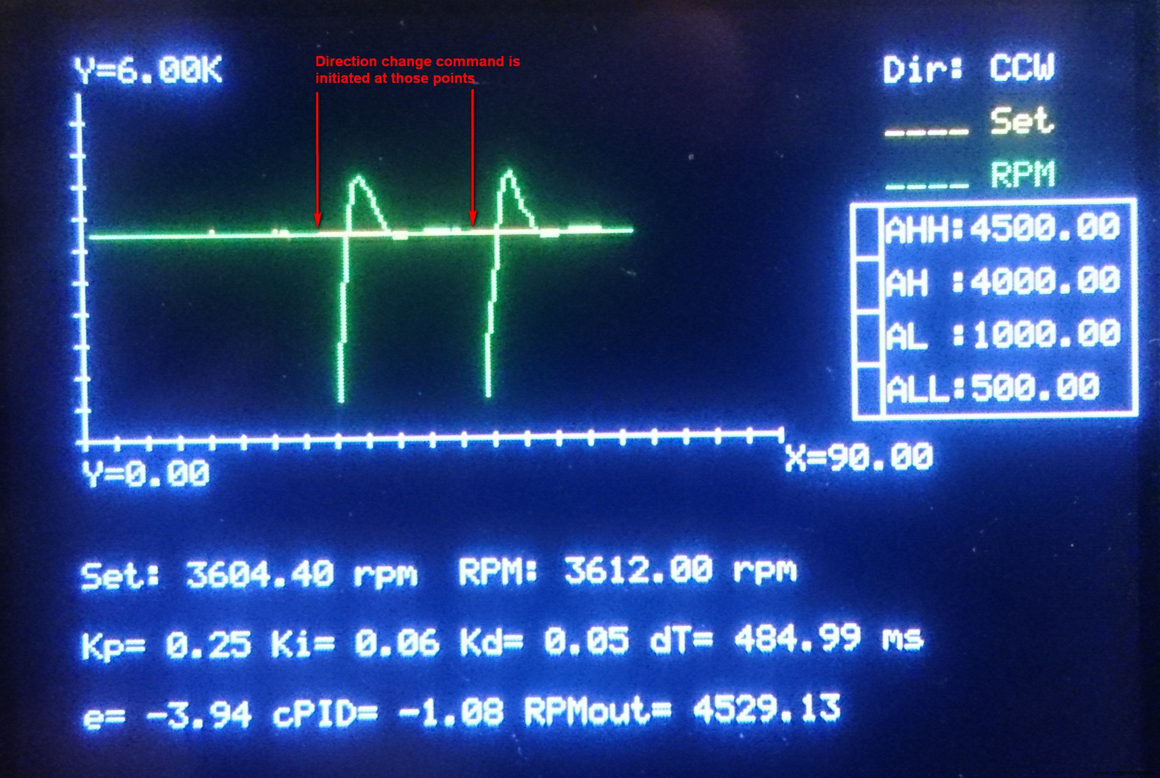
速读
在我的应用程序中,我使用了便宜的 HC-020K 速度传感器。它以电源电压的电平发送脉冲,数据表说电源电压为 5V。但是我的板子是 Arduino Due,它不能接受。所以我直接用 Due 的 3.3V 输出给它供电,是的,它起作用了。并写入以下函数读取频率和HC-020K输出。
int readFrequency(int _DI_FrequencyCounter_Pin, float _ReadingSpeed) { pinMode(_DI_FrequencyCounter_Pin,INPUT);字节_DigitalRead,_DigitalRead_Previous =0; unsigned long _Time =0, _Time_Init;浮动_频率=0; if ( (_ReadingSpeed<=0) || (_ReadingSpeed>10) ) 返回 (-1);其他{_Time_Init =micros();做 { _DigitalRead =digitalRead(_DI_FrequencyCounter_Pin); if ( (_DigitalRead_Previous==1) &&(_DigitalRead==0) ) _Frequency++; _DigitalRead_Previous =_DigitalRead; _Time =micros(); } while (_Time <(_Time_Init + (1000000/_ReadingSpeed))); } return (_ReadingSpeed * _Frequency); } 注意HC-020K的轮子有20个槽位,简单的读取频率除以20才能得到每秒转数作为频率。然后将结果乘以 60 得到 RPM。
RPM =60 * (float)readFrequency(_chSpeedRead,4) / _DiscSlots; 图形修饰
为了显示输入和结果,我使用了 Makeblock Me TFT LCD 并编写了 CommandToTFT() 函数来向它发送命令。其实这个功能的原因只是为了在需要的时候改变程序中单行的串行连接点。
Cartesian_Setup()、Cartesian_ClearPlotAreas() 和 Cartesian_Line() 函数分别用于准备图形绘制区域、到达横轴末端时清除绘图区域(这里是“时间”)和绘制图形。如果您对此处的图形功能感兴趣,请参阅 Makeblock Me TFT LCD 手册以获取更多详细信息,因为我不会在这里解释它们,因为它们实际上超出了本博客的范围。
结束
在这里,我分别复制了带和不带图形功能的程序,因此您可以单独或带图形查看速度和方向控制实现。此外,在代码中您可以找到对编程功能的进一步说明。
最后,通常您不能将直流电机的速度降低到其额定速度的 10-20% 以下,即使没有任何负载。但是,对于无负载的直流电机,一旦启动,通过使用PID控制可以降低到接近5%。
编辑(2018 年 2 月 25 日): 如果您想使用 NPN 晶体管而不是 PNP,您还必须考虑两种类型的反向电流。当触发(打开)电流从发射极流向 PNP 晶体管的集电极时,但对于 NPN 类型(从集电极到发射极)则相反。因此,PNP 晶体管被极化为 E(+) C(-) 而对于 NPN,它应该是 C(+) E(-)。
代码
- 带有图形修饰的代码
- 没有图形修饰的代码
带有图形修饰的代码Arduino
/* ########################################## ## Makeblock Me TFT LCD 的颜色常量###################################### ###### */#define _BLACK 0#define _RED 1#define _GREEN 2#define _BLUE 3#define _YELLOW 4#define _CYAN 5#define _PINK 6#define _WHITE 7/* ######## ##################################### I/O 分配####### ###################################### */int _chSpeedSet =A0, // 速度setpoint _chKp =A1, // PID 控制器的比例系数读数 _chKi =A2, // PID 控制器的积分系数读数 _chKd =A3, // PID 控制器的微分系数读数 _chMotorCmdCCW =3, // PWM 输出到电机用于计数器顺时针转动 _chMotorCmdCW =2, // PWM 输出到电机顺时针转动 _chSpeedRead =24, // 速度读数 _chDirection =25; //方向选择器读取/* ######################################## #### 其他常量######################################### ### */#define _minRPM 0 // 启动方向改变的最小 RPM #define _maxRPM 6000 // 最大 RPM 限制#define _Tmax 90 // 绘图的最大时间限制#define _DiscSlots 20 // 索引盘上的插槽数量/ * ############################################ 全局变量############################################### */细绳Cartesian_SetupDetails;boolean Direction, prevDirection;//报警设置float RALL=500.0, RAL=1000.0, RAH=4000.0, RAHH=4500.0;float Seconds=0.0, prevSeconds=0.0, prevRPM=0.0, prevRPM=0.0.RPM=0.RPMset 0.0, OutputRPM=0.0, Kp=0.0, Ki=0.0, Kd=0.0, Kpmax=2.0, Kimax=1.0, Kdmax=1.0, E=0.0, Eprev=0.0, dT=1.0;/* ###### ###################################### CommandToTFT(TFTCmd) Makeblock Me 命令函数TFT LCD 输入参数:(字符串)TFTCmd:命令字符串################################### ########## */void CommandToTFT(String TFTCmd){ /* 用于显示的串行连接 */ Serial1.println(TFTCmd); delay(5);}/* ###########CommandToTFT() 结束########### *//* ########### ################################*//* ############ ################################ Cartesian_Setup(Xmin, Xmax, Ymin, Ymax, Window_X1, Window_Y1, Window_X2 , Window_Y2, MinDashQty, ColorF, ColorX, ColorY) Makeblock Me TFT LCD 的笛卡尔 XY 轴绘制函数 输入参数:(float) Xmin, Xmax, Ymin, Ymax :轴范围值 (int) Window_X1, Window_Y1___:左上角图形窗口 (int) Window_X2, Window_Y2___:图形窗口的右下角 (int) MinDashQty_____________:最短轴上的虚线数量 (int) ColorB, ColorX, ColorY :Frame、X 轴和 Y 轴使用的绘制颜色外部函数 CommandToTFT().######################################### ### */String Cartesian_Setup( float Xmin, float Xmax, float Ymin, float Ymax, int Window_X1, int Window_Y1, int Window_X2, int Window_Y2, int MinDashQty, int ColorF, int ColorX, int ColorY ){ /* 屏幕限制 * / const int 显示分辨率X =319,显示分辨率Y =239; /* 限制标题字符串 */ String XminTxt; if (abs(Xmin)>=1000000000) XminTxt ="X=" + String (Xmin/1000000000) + "G"; else if (abs(Xmin)>=1000000) XminTxt ="X=" + String (Xmin/1000000) + "M"; else if (abs(Xmin)>=1000) XminTxt ="X=" + String (Xmin/1000) + "K"; else XminTxt ="X=" + String (Xmin);字符串 XmaxTxt; if (abs(Xmax)>=1000000000) XmaxTxt ="X=" + String (Xmax/1000000000) + "G"; else if (abs(Xmax)>=1000000) XmaxTxt ="X=" + String (Xmax/1000000) + "M"; else if (abs(Xmax)>=1000) XmaxTxt ="X=" + String (Xmax/1000) + "K"; else XmaxTxt ="X=" + String (Xmax);字符串 YminTxt; if (abs(Ymin)>=1000000000) YminTxt ="Y=" + String (Ymin/1000000000) + "G"; else if (abs(Ymin)>=1000000) YminTxt ="Y=" + String (Ymin/1000000) + "M"; else if (abs(Ymin)>=1000) YminTxt ="Y=" + String (Ymin/1000) + "K"; else YminTxt ="Y=" + String (Ymin);字符串 YmaxTxt; if (abs(Ymax)>=1000000000) YmaxTxt ="Y=" + String (Ymax/1000000000) + "G"; else if (abs(Ymax)>=1000000) YmaxTxt ="Y=" + String (Ymax/1000000) + "M"; else if (abs(Ymax)>=1000) YmaxTxt ="Y=" + String (Ymax/1000) + "K"; else YmaxTxt ="Y=" + String (Ymax); /* 限制 */ int XminPx =Window_X1+1; int XmaxPx =Window_X2-1; int YmaxPx =Window_Y1+1; int YminPx =Window_Y2-1; /* Origin */ int OriginX =XminPx + (int)( (XmaxPx - XminPx) * abs(Xmin) / (abs(Xmax)+abs(Xmin)) ); int OriginY =YmaxPx + (int)( (YminPx - YmaxPx) * abs(Ymax) / (abs(Ymax)+abs(Ymin)) ); /* 框架 */ CommandToTFT ( "BOX(" + String(Window_X1) + "," + String(Window_Y1)+ "," + String(Window_X2) + "," + String(Window_Y2)+ "," + String(颜色F) + ");" ); /* X 轴 */ CommandToTFT ( "PL(" + String(Window_X1+1) + "," + String(OriginY) + "," + String(Window_X2-1) + "," + String(OriginY) + ") ," + String(ColorX) + ");" ); /* Y 轴 */ CommandToTFT ( "PL(" + String(OriginX) + "," + String(Window_Y1+1) + "," + String(OriginX) + "," + String(Window_Y2-1) + ") ," + String(ColorY) + ");" ); /* 短划线:最小短划线数量由“MinDashQty”给出,并将在相对于原点的最短轴侧划线。在其他部分,要标记的破折号应考虑与最短轴边的比率来确定。 */ /* 破折号 */ int XlengthLeft =abs(XminPx-OriginX); int XlengthRight =abs(XmaxPx-OriginX); int YlengthLower =abs(YminPx-OriginY); int YlengthUpper =abs(YmaxPx-OriginY); int XlengthLeft_Mod, XlengthRight_Mod, YlengthLower_Mod, YlengthUpper_Mod;如果 (XlengthLeft<=1) XlengthLeft_Mod=32767;否则 XlengthLeft_Mod=XlengthLeft;如果 (XlengthRight<=1) XlengthRight_Mod=32767;否则 XlengthRight_Mod=XlengthRight;如果 (YlengthLower<=1) YlengthLower_Mod=32767;否则 YlengthLower_Mod=YlengthLower;如果 (YlengthUpper<=1) YlengthUpper_Mod=32767;否则 YlengthUpper_Mod=YlengthUpper; int MinAxisLength =min ( min (XlengthLeft_Mod,XlengthRight_Mod), min (YlengthLower_Mod,YlengthUpper_Mod) ); int XdashesLeft =MinDashQty * XlengthLeft / MinAxisLength; int XdashesRight =MinDashQty * XlengthRight / MinAxisLength; int YdashesLower =MinDashQty * YlengthLower / MinAxisLength; int YdashesUpper =MinDashQty * YlengthUpper / MinAxisLength; int DashingInterval=2; // Min.interval btw.dashes /* X-Dash L */ DashingInterval =(int) (XlengthLeft / XdashesLeft); if (!(DashingInterval<2)) for (int i=OriginX; i>=XminPx; i-=DashingInterval) CommandToTFT ( "PL(" + String(i) + "," + String(OriginY-2) + " ," + String(i) + "," + String(OriginY+2) + "," + String(ColorX) + ");" ); /* X-Dash R */ DashingInterval =(int) (XlengthRight / XdashesRight); if (!(DashingInterval<2)) for (int i=OriginX; i<=XmaxPx; i+=DashingInterval) CommandToTFT ( "PL(" + String(i) + "," + String(OriginY-2) + ", " + String(i) + "," + String(OriginY+2) + "," + String(ColorX) + ");" ); /* Y-Dash-L */ DashingInterval =(int) (YlengthLower / YdashesLower); if (!(DashingInterval<2)) for (int i=OriginY; i<=YminPx; i+=DashingInterval) CommandToTFT ( "PL(" + String(OriginX-2) + "," + String(i) + ", " + String(OriginX+2) + "," + String(i) + "," + String(ColorY) + ");" ); /* Y-Dash-U */ DashingInterval =(int) (YlengthUpper / YdashesUpper); if (!(DashingInterval<2)) for (int i=OriginY; i>=YmaxPx; i-=DashingInterval) CommandToTFT ( "PL(" + String(OriginX-2) + "," + String(i) + " ," + String(OriginX+2) + "," + String(i) + "," + String(ColorY) + ");" ); /* 计算坐标以显示轴端点值 */ int XminTxtX =Window_X1 - (int)(XminTxt.length()*6) - 1, XminTxtY =OriginY, XmaxTxtX =Window_X2 + 1, XmaxTxtY =OriginY, YminTxtX =OriginX, Y =Window_Y2 + 1,YmaxTxtX =OriginX,YmaxTxtY =Window_Y1 - 12 - 1; /* 控件:如果任何坐标为-1,则它应超出显示范围,并且不应显示相应的值 */ if (XminTxtX<0) XminTxtX =-1;如果 ( (XminTxtY-12) <0 ) XminTxtY =-1; if ( (XmaxTxtX+6*XmaxTxt.length())> DisplayResolutionX ) XmaxTxtX =-1; if ( (XmaxTxtY+12)> DisplayResolutionY ) XmaxTxtY =-1; if ( (YminTxtX+6*YminTxt.length())> DisplayResolutionX ) YminTxtX =-1; if ( (YminTxtY+12)> DisplayResolutionY ) YminTxtY =-1; if ( (YmaxTxtX+6*YmaxTxt.length())> DisplayResolutionX ) YmaxTxtX =-1;如果 (YmaxTxtY<0) YmaxTxtY =-1; /* 范围限制标题 */ if ( ( XminTxtX !=-1 ) &&( XminTxtY !=-1 ) ) CommandToTFT( "DS12(" + String(XminTxtX) + "," + String(XminTxtY) + ",'" + String(XminTxt) + "'," + String(ColorX) + ");" ); if ( ( XmaxTxtX !=-1 ) &&( XmaxTxtY !=-1 ) ) CommandToTFT( "DS12(" + String(XmaxTxtX) + "," + String(XmaxTxtY) + ",'" + String(XmaxTxt) + " '," + String(ColorX) + ");" ); if ( ( ( YminTxtX !=-1 ) &&( YminTxtY !=-1 ) ) CommandToTFT( "DS12(" + String(YminTxtX) + "," + String(YminTxtY) + ",'" + String(YminTxt) + " '," + String(ColorY) + ");" ); if ( ( YmaxTxtX !=-1 ) &&( YmaxTxtY !=-1 ) ) CommandToTFT( "DS12(" + String(YmaxTxtX) + "," + String(YmaxTxtY) + ",'" + String(YmaxTxt) + " '," + String(ColorY) + ");" ); /* 返回值 String Cartesian_Setup() 将返回以下格式的字符串打包图形配置: "" 字符串以'<'开头,以'>'结尾.每个值都由 ',' 分隔 */ /* 初始化 */ String Cartesian_SetupDetails ="<"; Cartesian_SetupDetails +=( String(Xmin) + "," ); Cartesian_SetupDetails +=( String(Xmax) + "," ); Cartesian_SetupDetails +=( String(Ymin) + "," ); Cartesian_SetupDetails +=( String(Ymax) + "," ); Cartesian_SetupDetails +=( String(Window_X1) + "," ); Cartesian_SetupDetails +=( String(Window_Y1) + "," ); Cartesian_SetupDetails +=( String(Window_X2) + "," ); Cartesian_SetupDetails +=( String(Window_Y2) + "," ); /* 关闭 */ Cartesian_SetupDetails +=">";return Cartesian_SetupDetails;}/* ##########Cartesian_Setup() 结束 ########## *// * ############################################# * //* ############################################ Cartesian_ClearPlotAreas(Descriptor, Color) Makeblock Me TFT LCD 的绘图区域重置/清除函数输入参数:(字符串)描述符:设置描述符 - 由 Cartesian_Setup() 返回 (int) Color______:用于填充绘图区域的颜色使用外部函数 CommandToTFT ().############################################ */void Cartesian_ClearPlotAreas(String Descriptor, int Color){ int X1,Y1,X2,Y2; /* 绘图区域的边界坐标 */ /* 从描述符中提取值 */ /* L[0] L[1] L[2] L[3] W[0] W[1] W[2] W[3 ] */ /* Xmin Xmax Ymin Ymax Window_X1 Window_Y1 Window_X2 Window_Y2 */ float L[4];整数 W[4]; /* 存储在描述符中的值 */ int j=0; /* 计数器 */ String D_Str =""; for (int i=1; i<=(Descriptor.length()-1); i++) if ( Descriptor[i] ==',' ) { if (j<4) L[j]=D_Str.toFloat( );否则 W[j-4]=D_Str.toInt(); D_Str=""; j++; } else D_Str +=Descriptor[i]; /* 原点 */ int OriginX =(W[0]+1) + (int)( ( (W[2]-1) - (W[0]+1) ) * abs(L[0]) / ( abs(L[1])+abs(L[0]))); int OriginY =(W[1]+1) + (int)( ( (W[3]-1) - (W[1]+1) ) * abs(L[3]) / (abs(L[3]) ])+abs(L[2]))); /* 清除绘图区域 */ //Area.1 :X+ Y+ X1 =OriginX + 2; Y1 =W[1] + 1; X2 =W[2] - 1; Y2 =OriginY - 2; CommandToTFT ( "BOXF(" + String(X1) + "," + String(Y1) + "," + String(X2) + "," + String(Y2) + "," + String(Color) + ");"); //Area.2 :X- Y+ X1 =W[0] + 1; Y1 =W[1] + 1; X2 =OriginX - 2; Y2 =OriginY - 2; CommandToTFT ( "BOXF(" + String(X1) + "," + String(Y1) + "," + String(X2) + "," + String(Y2) + "," + String(Color) + ");"); //Area.3 :X- Y- X1 =W[0] + 1; Y1 =原点Y + 2; X2 =OriginX - 2; Y2 =W[3] - 1; CommandToTFT ( "BOXF(" + String(X1) + "," + String(Y1) + "," + String(X2) + "," + String(Y2) + "," + String(Color) + ");"); //Area.4 :X+ Y- X1 =OriginX + 2; Y1 =原点Y + 2; X2 =W[2] - 1; Y2 =W[3] - 1; CommandToTFT ( "BOXF(" + String(X1) + "," + String(Y1) + "," + String(X2) + "," + String(Y2) + "," + String(Color) + ");" );} /* ########### Cartesian_ClearPlotAreas()结束########### *//* ############ ##########################################*//* # ##########################################Cartesian_Line(Xp, Yp、X、Y、描述符、颜色)用于 Makeblock Me TFT LCD 输入参数的笛卡尔线函数:(int)Xp、Yp_____:先前绘图坐标 - y 值与 x (int)X、Y_______:当前绘图坐标 - y 值与x (String) Descriptor :Setup Descriptor - 由 Cartesian_Setup() 返回 (int) Color______:标记颜色用于 (x,y) 使用外部函数 CommandToTFT().############# ################################ */void Cartesian_Line(float Xp, float Yp, float X, float Y , String Descriptor, int Color){ /* 从描述符中提取值 */ /* L[0] L[1] L[2] L[3] W[0] W[1] W[2] W[3] */ /* Xmin Xmax Ymin Ymax Window_X1 Window_Y1 Window_X2 Window_Y2 */ float L[4 ];整数 W[4]; /* 存储在描述符中的值 */ int j=0; /* 计数器 */ String D_Str =""; for (int i=1; i<=(Descriptor.length()-1); i++) if ( Descriptor[i] ==',' ) { if (j<4) L[j]=D_Str.toFloat( );否则 W[j-4]=D_Str.toInt(); D_Str=""; j++; } else D_Str +=Descriptor[i]; /* 原点 */ int OriginX =(W[0]+1) + (int)( ( (W[2]-1) - (W[0]+1) ) * abs(L[0]) / ( abs(L[1])+abs(L[0]))); int OriginY =(W[1]+1) + (int)( ( (W[3]-1) - (W[1]+1) ) * abs(L[3]) / (abs(L[3]) ])+abs(L[2]))); int XminPx =W[0] + 1; int XmaxPx =W[2] - 1; int YmaxPx =W[1] + 1; int YminPx =W[3] - 1;如果 (Y>L[3]) Y=L[3];如果 (Y
=(OriginX-2) ) &&( DispXp <=(OriginX+2) ) ) || ( ( DispYp>
=(OriginY-2) ) &&( DispYp <=(OriginY+2) ) ) || ( ( DispX>=(OriginX-2) ) &&( DispX <=(OriginX+2) ) ) || ( ( DispY>=(OriginY-2) ) &&( DispY <=(OriginY+2) ) ) )) CommandToTFT( "PL(" + String(DispXp) + "," + String(DispYp) + "," + String(DispX) + "," + String(DispY) + "," + String(Color) ) + ");" );}/* ########### Cartesian_Line() 结束########### *//* ######## ##################################### *//* ####### ####################################readFrequency(_DI_FrequencyCounter_Pin, _ReadingSpeed) 读频函数输入参数: (int) _DI_FrequencyCounter_Pin :要读取的数字引脚(浮点数) _ReadingSpeed____________: 0...10 之间的自定义读取速度(注 1) 注 1:_ReadingSpeed 是一个值,用于指定更改计数的时间。不能为0(零)、负值或大于10的值。当_ReadingSpeed改变时,1秒除以该值计算所需的计数时间。例如; - _ReadingSpeed =0.1 -> 输入应在 10 秒内计数 (=1/0.1) - _ReadingSpeed =0.5 -> 输入应在 2 秒内计数 (=1/0.5) - _ReadingSpeed =2.0 -> 输入应在 0.5 期间计数秒 (=1/2) - _ReadingSpeed =4.0 -> 输入应在 0.25 秒内进行计数 (=1/4) 重要的是要注意,增加 _ReadingSpeed 是不利的,尤其是在较低频率(通常低于 100 Hz)时,因为计数误差会增加高达 20%~40% 通过降低频率。##################################### ######## */int readFrequency(int _DI_FrequencyCounter_Pin, float _ReadingSpeed){ pinMode(_DI_FrequencyCounter_Pin,INPUT);字节_DigitalRead,_DigitalRead_Previous =0; unsigned long _Time =0, _Time_Init;浮动_频率=0; if ( (_ReadingSpeed<=0) || (_ReadingSpeed>10) ) 返回 (-1);其他{_Time_Init =micros();做 { _DigitalRead =digitalRead(_DI_FrequencyCounter_Pin); if ( (_DigitalRead_Previous==1) &&(_DigitalRead==0) ) _Frequency++; _DigitalRead_Previous =_DigitalRead; _Time =micros(); } while (_Time <(_Time_Init + (1000000/_ReadingSpeed))); } return (_ReadingSpeed * _Frequency);}/* ########### End of readFrequency() ########### *//* ############################################## *//* ############################################### controllerPID(RangeMin, RangeMax, _E, _Eprev, _dT, _Kp, _Ki, _Kd) PID Controller Function Input Parameters:(float) RangeMin:Minimum limit for output (float) RangeMax:Maximum limit for output (float) _E_____:Current error signal (float) _Eprev :Previous error signal (float) _dT____:Time difference as seconds (float) _Kp____:Proportional coefficient (float) _Ki____:Integral coefficient (float) _Kp____:Derivative coefficient Adjustment procedure:1. Set Kp=0, Ki=0, Kd=0. 2. Start to increase Kp until the system oscillates at fixed period (Pc) and note critical gain Kc =Kp. 3. Adjust final coefficients as follows. for P-control only :Kp =0.50*Kc for PI-control only :Kp =0.45*Kc, Ki =1.2/Pc for PID-control :Kp =0.60*Kc, Ki =2.0/Pc, Kd=Pc/8 4. Fine tuning could be done by slightly changing each coefficient.############################################### */ float controllerPID(float _E, float _Eprev, float _dT, float _Kp, float _Ki, float _Kd){ float P, I, D; /* Base Formula:U =_Kp * ( _E + 0.5*(1/_Ki)*(_E+_Eprev)*_dT + _Kd*(_E-_Eprev)/_dT ); */ P =_Kp * _E; /* Proportional Component */ I =_Kp * 0.5 * _Ki * (_E+_Eprev) * _dT; /* Integral Component */ D =_Kp * _Kd * (_E-_Eprev) / _dT; /* Derivative Component */ return (P+I+D);}/* ########### End of controllerPID() ########### *//* ############################################## *//* ############################################### Setup############################################### */void setup(){ Serial1.begin(9600); Serial1.println("CLS(0);");delay(20); analogReadResolution(12); pinMode(_chDirection,INPUT); // Direction selector reading pinMode(_chMotorCmdCCW,OUTPUT); // PWM output to motor for counter-clockwise turn pinMode(_chMotorCmdCW,OUTPUT); // PWM output to motor for clockwise turn // Initial killing the PWM outputs to motor analogWrite(_chMotorCmdCCW,0); analogWrite(_chMotorCmdCW,0); // Initial reading for direction selection Direction=digitalRead(_chDirection); // HIGH=CCW, LOW=CW prevDirection=Direction; // The section below prepares TFT LCD // Cartesian_Setup(Xmin, Xmax, Ymin, Ymax, Window_X1, Window_Y1, Window_X2, Window_Y2, MinDashQty, ColorF, ColorX, ColorY) Cartesian_SetupDetails =Cartesian_Setup(0, _Tmax, _minRPM, _maxRPM, 20, 20, 220, 120, 10, 0, 7, 7); CommandToTFT("DS12(250,10,'Dir:CW '," + String(_WHITE) + ");"); CommandToTFT("DS12(250,25,'____ Set'," + String(_YELLOW) + ");"); CommandToTFT("DS12(250,40,'____ RPM'," + String(_GREEN) + ");"); /* Alarm Values */ CommandToTFT("DS12(250,55,'AHH:" + String(RAHH) + "'," + String(_WHITE) + ");"); CommandToTFT("DS12(250,70,'AH :" + String(RAH) + "'," + String(_WHITE) + ");"); CommandToTFT("DS12(250,85,'AL :" + String(RAL) + "'," + String(_WHITE) + ");"); CommandToTFT("DS12(250,100,'ALL:"+ String(RALL) + "'," + String(_WHITE) + ");"); /* Alarm Window */ CommandToTFT("BOX(240,55,319,115," + String(_WHITE) + ");"); /* Alarm Lamps */ CommandToTFT("BOX(240,55,248,70," + String(_WHITE) + ");"); CommandToTFT("BOX(240,70,248,85," + String(_WHITE) + ");"); CommandToTFT("BOX(240,85,248,100," + String(_WHITE) + ");"); CommandToTFT("BOX(240,100,248,115," + String(_WHITE) + ");");}/* ############################################### Loop############################################### */void loop(){ // Initialization Time:Necessary for PID controller. int InitTime =micros(); // X-Axis Auto-Reset for Graphing if ( Seconds> 90.0 ) { Seconds =0.0; Cartesian_ClearPlotAreas(Cartesian_SetupDetails,0); } // Reading Inputs /* Controller Coefficients */ Kp =Kpmax * (float)analogRead(_chKp) / 4095; Ki =Kimax * (float)analogRead(_chKi) / 4095; Kd =Kdmax * (float)analogRead(_chKd) / 4095; /* Direction Selector */ Direction =digitalRead(_chDirection); /* HIGH=CCW, LOW=CW */ /* Actual RPM and RPM Setpoint Note that maximum selectable RPM is 5000. */ RPM =60 * (float)readFrequency(_chSpeedRead,4) / _DiscSlots; RPMset =5000 * (float)analogRead(_chSpeedSet) / 4095; // Calculations and Actions /* Error Signal, PID Controller Output and Final Output (PWM) to Motor */ E =RPMset - RPM; float cPID =controllerPID(E, Eprev, dT, Kp, Ki, Kd); if ( RPMset ==0 ) OutputRPM =0; else OutputRPM =OutputRPM + cPID; if ( OutputRPM <_minRPM ) OutputRPM =_minRPM; if ( OutputRPM> _maxRPM ) OutputRPM =_maxRPM; /* Changing Direction when inverted Note that no any graphical indication is performed on this function. */ if ( Direction !=prevDirection ) { /* Killing both of the PWM outputs to motor */ analogWrite(_chMotorCmdCCW,0); analogWrite(_chMotorCmdCW,0); /* Wait until motor speed decreases */ do { RPM =60 * (float)readFrequency(_chSpeedRead,4) / _DiscSlots; } while ( RPM> _minRPM ); } // Writing Outputs if (Direction==HIGH) analogWrite(_chMotorCmdCCW,(int)(255*OutputRPM/_maxRPM)); else analogWrite(_chMotorCmdCW, (int)(255*OutputRPM/_maxRPM)); // Graphing /* Indicating Direction */ if (Direction==HIGH) CommandToTFT("DS12(280,10,'CCW '," + String(_WHITE) + ");"); else CommandToTFT("DS12(280,10,'CW '," + String(_WHITE) + ");"); /* Plotting Curve */ Cartesian_Line(prevSeconds, prevRPMset, Seconds, RPMset, Cartesian_SetupDetails, _YELLOW); Cartesian_Line(prevSeconds, prevRPM, Seconds, RPM, Cartesian_SetupDetails, _GREEN); /* Indicating values of RPM Setpoint, PID Controller Coefficients, Error Signal, PID Controller Output and Final RPM Output (PWM) */ CommandToTFT( "DS12(20,150,'Set:" + String(RPMset) + " rpm " + "RPM:" + String(RPM) + " rpm '," + String(_WHITE) + ");"); CommandToTFT( "DS12(20,170,'Kp=" + String(Kp) + " " + "Ki=" + String(Ki) + " " + "Kd=" + String(Kd) + " " + "dT=" + String(dT*1000) + " ms '," + String(_WHITE) + ");"); CommandToTFT( "DS12(20,190,'e=" + String(E) + " " + "cPID=" + String(cPID) + " " + "RPMout=" + String(OutputRPM) + " '," + String(_WHITE) + ");"); /* Resetting Alarm Lamps */ CommandToTFT("BOXF(241,56,247,69," + String(_BLACK) + ");"); CommandToTFT("BOXF(241,71,247,84," + String(_BLACK) + ");"); CommandToTFT("BOXF(241,86,247,99," + String(_BLACK) + ");"); CommandToTFT("BOXF(241,101,247,114," + String(_BLACK) + ");"); /* Activating Necessary Alarm Lamps */ if (RPM>=RAHH) CommandToTFT("BOXF(241,56,247,69," + String(_RED) + ");"); if ((RPM>=RAH)&&(RPMRALL)&&(RPM<=RAL)) CommandToTFT("BOXF(241,86,247,99," + String(_RED) + ");"); if (RPM<=RALL) CommandToTFT("BOXF(241,101,247,114," + String(_RED) + ");"); // Storing Values generated on previous cycle Eprev =E; prevRPMset =RPMset; prevRPM =RPM; prevSeconds =Seconds; prevDirection =Direction; // Calculating control application cycle time and passed Seconds dT =float ( micros() - InitTime ) / 1000000.0; Seconds+=dT; }
Code without Graphical Touch-UpsArduino
/* ############################################### I/O Assignments############################################### */int _chSpeedSet =A0, // Speed setpoint _chKp =A1, // Proportional coefficient reading for PID controller _chKi =A2, // Integral coefficient reading for PID controller _chKd =A3, // Derivative coefficient reading for PID controller _chMotorCmdCCW =3, // PWM output to motor for counter-clockwise turn _chMotorCmdCW =2, // PWM output to motor for clockwise turn _chSpeedRead =24, // Speed reading _chDirection =25; // Direction selector reading/* ############################################### Other Constants ############################################### */#define _minRPM 0 // Minimum RPM to initiate direction changing#define _maxRPM 6000 // Maximum RPM limit#define _DiscSlots 20 // Qty of slots on Index Disc/* ############################################### Global Variables############################################### */boolean Direction, prevDirection;float RPM=0.0, RPMset=0.0, OutputRPM=0.0, Kp=0.0, Ki=0.0, Kd=0.0, Kpmax=2.0, Kimax=1.0, Kdmax=1.0, E=0.0, Eprev=0.0, dT=1.0;/* ############################################### readFrequency(_DI_FrequencyCounter_Pin, _ReadingSpeed) Frequency Reading Function Input Parameters:(int) _DI_FrequencyCounter_Pin :Digital pin to be read (float) _ReadingSpeed____________:Custom reading speed between 0...10 (Note.1) Note.1:_ReadingSpeed is a value to specify how long shall the changes be counted. It cannot be 0(zero), negative values or a value greater than 10. When _ReadingSpeed changed, 1 second shall be divided by this value to calculate required counting duration. For example; - _ReadingSpeed =0.1 -> input shall be counted during 10 seconds (=1/0.1) - _ReadingSpeed =0.5 -> input shall be counted during 2 seconds (=1/0.5) - _ReadingSpeed =2.0 -> input shall be counted during 0.5 seconds (=1/2) - _ReadingSpeed =4.0 -> input shall be counted during 0.25 seconds (=1/4) Importantly note that, increasing of _ReadingSpeed is a disadvantage especially on lower frequencies (generally below 100 Hz) since counting error increases up to 20%~40% by decreasing frequency.############################################### */int readFrequency(int _DI_FrequencyCounter_Pin, float _ReadingSpeed){ pinMode(_DI_FrequencyCounter_Pin,INPUT); byte _DigitalRead, _DigitalRead_Previous =0; unsigned long _Time =0, _Time_Init; float _Frequency =0; if ( (_ReadingSpeed<=0) || (_ReadingSpeed>10) ) return (-1); else { _Time_Init =micros(); do { _DigitalRead =digitalRead(_DI_FrequencyCounter_Pin); if ( (_DigitalRead_Previous==1) &&(_DigitalRead==0) ) _Frequency++; _DigitalRead_Previous =_DigitalRead; _Time =micros(); } while ( _Time <(_Time_Init + (1000000/_ReadingSpeed)) ); } return (_ReadingSpeed * _Frequency);}/* ########### End of readFrequency() ########### *//* ############################################## *//* ############################################### controllerPID(RangeMin, RangeMax, _E, _Eprev, _dT, _Kp, _Ki, _Kd) PID Controller Function Input Parameters:(float) RangeMin:Minimum limit for output (float) RangeMax:Maximum limit for output (float) _E_____:Current error signal (float) _Eprev :Previous error signal (float) _dT____:Time difference as seconds (float) _Kp____:Proportional coefficient (float) _Ki____:Integral coefficient (float) _Kp____:Derivative coefficient Adjustment procedure:1. Set Kp=0, Ki=0, Kd=0. 2. Start to increase Kp until the system oscillates at fixed period (Pc) and note critical gain Kc =Kp. 3. Adjust final coefficients as follows. for P-control only :Kp =0.50*Kc for PI-control only :Kp =0.45*Kc, Ki =1.2/Pc for PID-control :Kp =0.60*Kc, Ki =2.0/Pc, Kd=Pc/8 4. Fine tuning could be done by slightly changing each coefficient.############################################### */ float controllerPID(float _E, float _Eprev, float _dT, float _Kp, float _Ki, float _Kd){ float P, I, D; /* Base Formula:U =_Kp * ( _E + 0.5*(1/_Ki)*(_E+_Eprev)*_dT + _Kd*(_E-_Eprev)/_dT ); */ P =_Kp * _E; /* Proportional Component */ I =_Kp * 0.5 * _Ki * (_E+_Eprev) * _dT; /* Integral Component */ D =_Kp * _Kd * (_E-_Eprev) / _dT; /* Derivative Component */ return (P+I+D);}/* ########### End of controllerPID() ########### *//* ############################################## *//* ############################################### Setup############################################### */void setup(){ analogReadResolution(12); pinMode(_chDirection,INPUT); // Direction selector reading pinMode(_chMotorCmdCCW,OUTPUT); // PWM output to motor for counter-clockwise turn pinMode(_chMotorCmdCW,OUTPUT); // PWM output to motor for clockwise turn // Initial killing the PWM outputs to motor analogWrite(_chMotorCmdCCW,0); analogWrite(_chMotorCmdCW,0); // Initial reading for direction selection Direction=digitalRead(_chDirection); // HIGH=CCW, LOW=CW prevDirection=Direction;}/* ############################################### Loop############################################### */void loop(){ // Initialization Time:Necessary for PID controller. int InitTime =micros(); // Reading Inputs /* Controller Coefficients */ Kp =Kpmax * (float)analogRead(_chKp) / 4095; Ki =Kimax * (float)analogRead(_chKi) / 4095; Kd =Kdmax * (float)analogRead(_chKd) / 4095; /* Direction Selector */ Direction =digitalRead(_chDirection); /* HIGH=CCW, LOW=CW */ /* Actual RPM and RPM Setpoint Note that maximum selectable RPM is 5000. */ RPM =60 * (float)readFrequency(_chSpeedRead,4) / _DiscSlots; RPMset =5000 * (float)analogRead(_chSpeedSet) / 4095; // Calculations and Actions /* Error Signal, PID Controller Output and Final Output (PWM) to Motor */ E =RPMset - RPM; float cPID =controllerPID(E, Eprev, dT, Kp, Ki, Kd); if ( RPMset ==0 ) OutputRPM =0; else OutputRPM =OutputRPM + cPID; if ( OutputRPM <_minRPM ) OutputRPM =_minRPM; if ( OutputRPM> _maxRPM ) OutputRPM =_maxRPM; /* Changing Direction when inverted */ if ( Direction !=prevDirection ) { /* Killing both of the PWM outputs to motor */ analogWrite(_chMotorCmdCCW,0); analogWrite(_chMotorCmdCW,0); /* Wait until motor speed decreases */ do { RPM =60 * (float)readFrequency(_chSpeedRead,4) / _DiscSlots; } while ( RPM> _minRPM ); } // Writing Outputs if (Direction==HIGH) analogWrite(_chMotorCmdCCW,(int)(255*OutputRPM/_maxRPM)); else analogWrite(_chMotorCmdCW, (int)(255*OutputRPM/_maxRPM)); // Storing Values generated on previous cycle Eprev =E; prevDirection =Direction; // Calculating control application cycle time and passed Seconds dT =float ( micros() - InitTime ) / 1000000.0;} 示意图
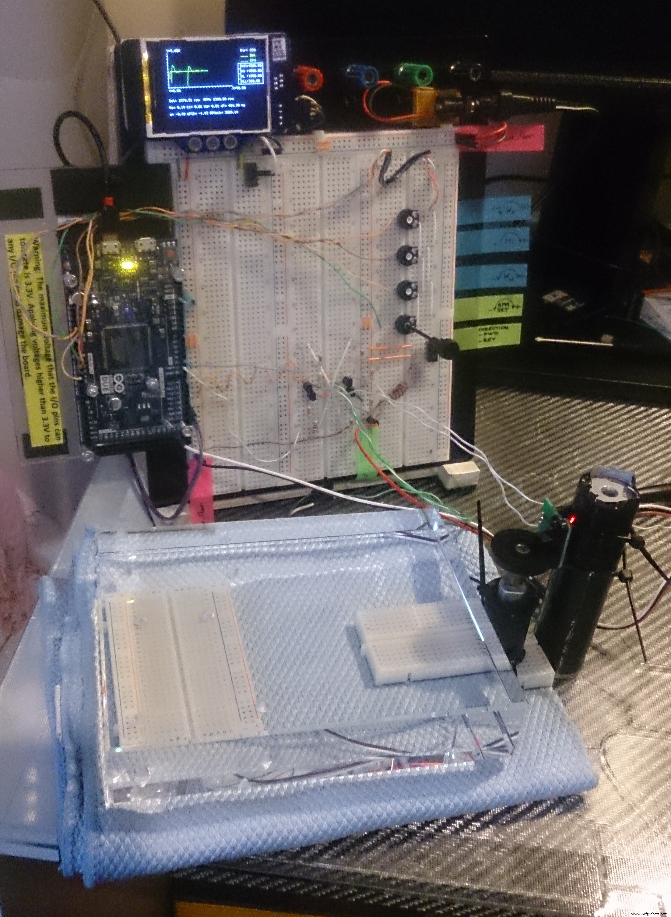
It's a prototype to explain DC motor speed control by using PID controller, and what should be considered for reversing.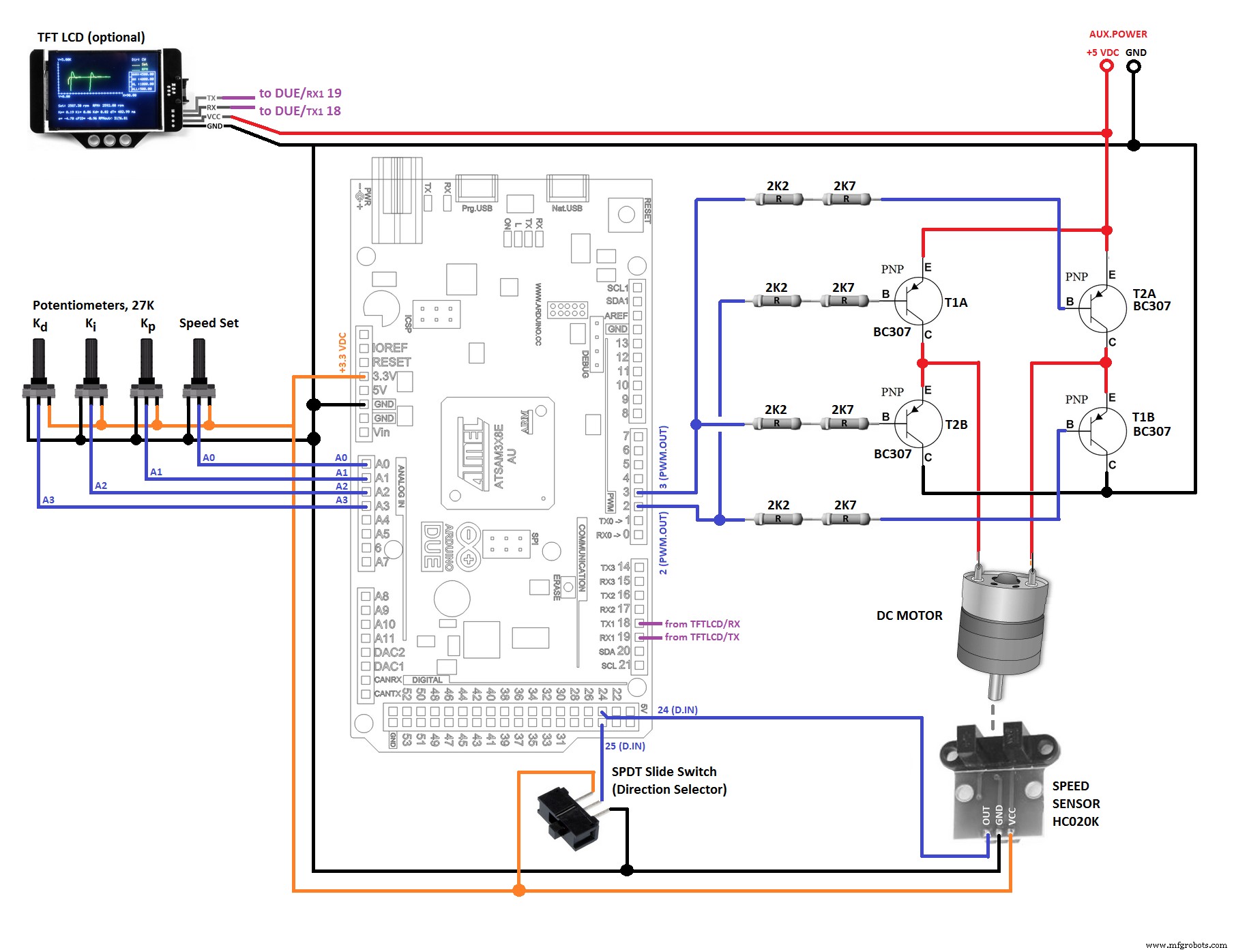
制造工艺