

克拉沃克斯!无线、运动和触摸感应仪器
组件和用品
 |
| × | 2 | |||
 |
| × | 2 | |||
| × | 1 | ||||
| × | 2 | ||||
| × | 2 | ||||
 |
| × | 2 | |||
 |
| × | 2 | |||
| × | 5 | ||||
 |
| × | 2 | |||
| × | 2 | ||||
 |
| × | 3 | |||
| × | 5 | ||||
| × | 3 | ||||
 |
| × | 3 | |||
| × | 1 | ||||
| × | 1 | ||||
| × | 1 | ||||
| × | 1 | ||||
| × | 1 | ||||
| × | 1 | ||||
| × | 1 | ||||
| × | 1 | ||||
| × | 1 |
必要的工具和机器
 |
| |||
| ||||
| ||||
| ||||
| ||||
| ||||
| ||||
 |
| |||
|
应用和在线服务
 |
| |||
|
关于这个项目
一个新的 乐器种类
Kravox 是瑞典隆德大学研究项目的一部分,旨在为数字乐器控制器提供传统机械乐器的感觉。
现在 Kravox 将面向所有人开放,并作为一个音乐实验平台,因此创建此详细教程是为了让尽可能多的人使用这种令人兴奋的新乐器!
如何玩 Kravox
玩 Kravox 非常简单。想象一下,您正在玩扫帚这样的普通物体,您触摸和移动它在空间中的方式控制着声音的产生方式。在此视频中查看并了解如何玩 Kravox。
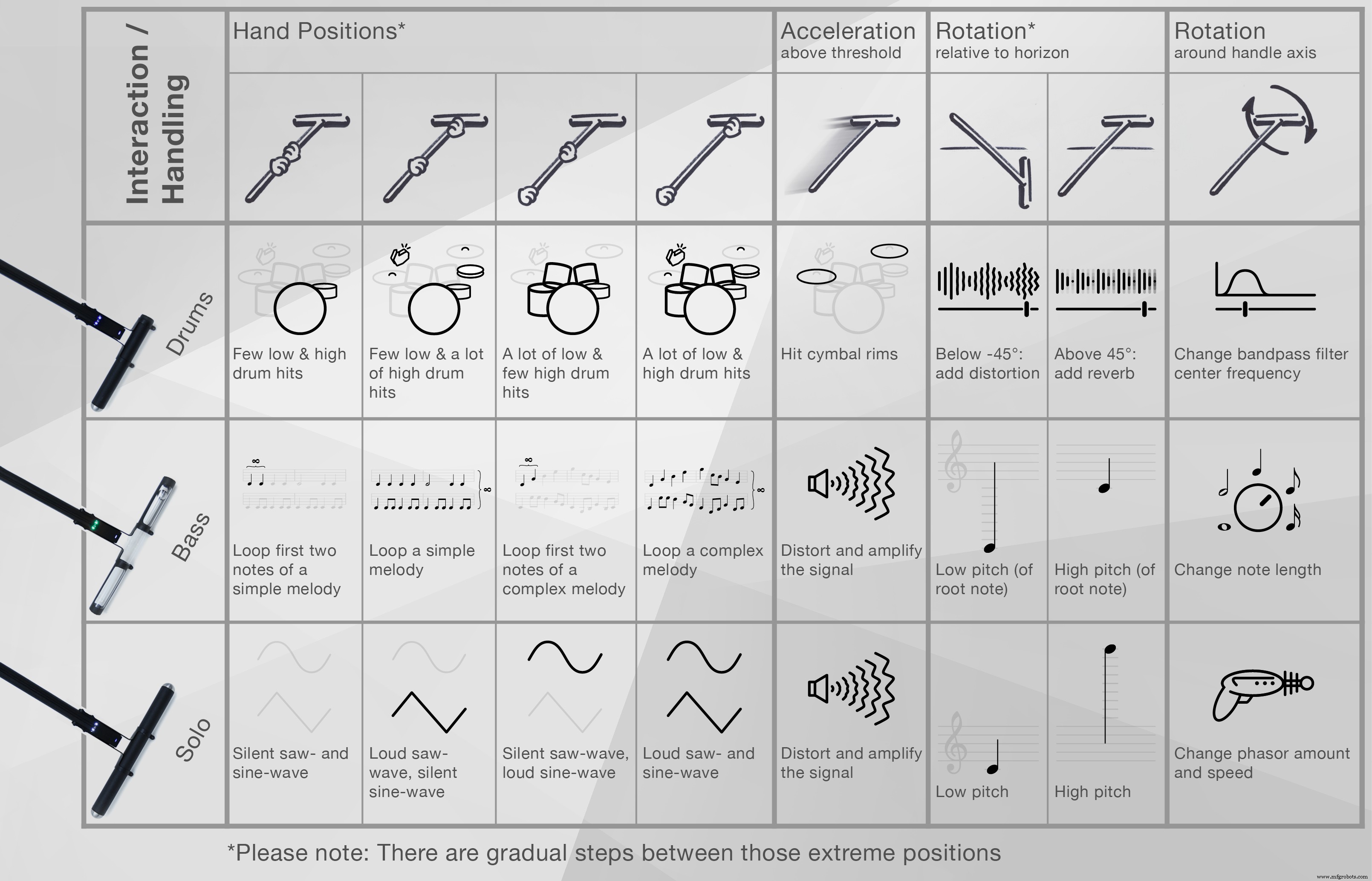
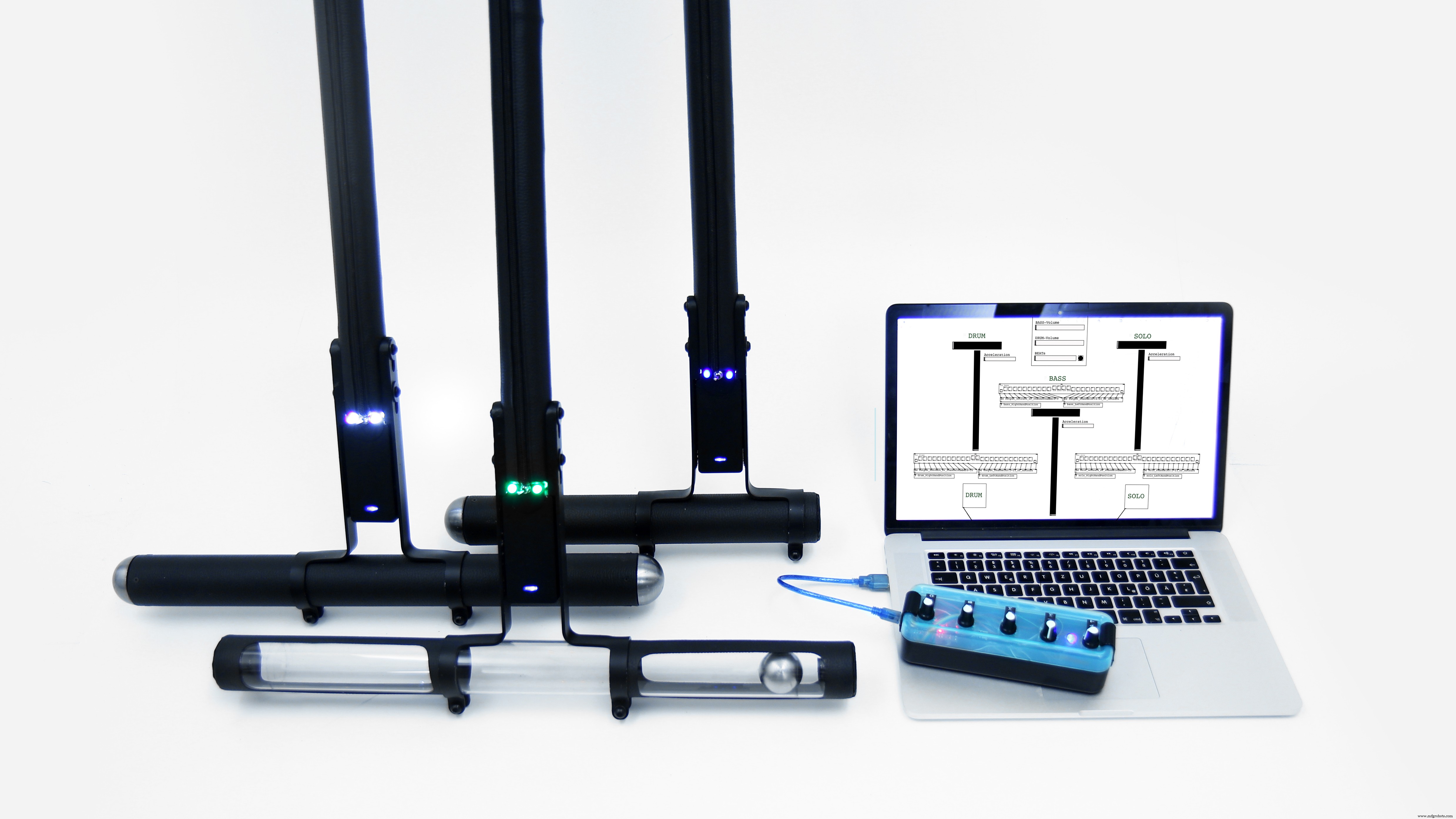
Kravox 是什么?
Kravox 是一种跨平台兼容的开源数字乐器,由三个组件组成:控制器、接收器和软件。
控制器/s
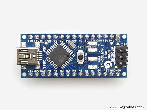
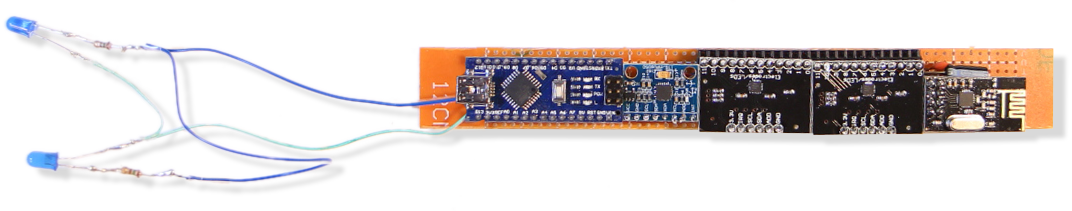
最多可以连接三个无线控制器设备。每个控制器处理来自数字 MPU-6050 陀螺仪的方向和加速度数据以及来自连接到 Arduino Nano 的两个 MPR121 触摸传感器板的触摸数据。控制器通过 nRF24L01 无线电收发器将数据发送到接收器设备。
如果要使用多个控制器,则需要为第二个和第三个控制器分配单独的地址。有关分配地址的更多信息,请参阅控制器代码的声明 / NRF24L01 部分中的信息。
接收器
接收器通过 USB 将从控制器接收到的数据与从多个电位计收集的数据一起传递到连接的计算机。提供的接收器设备代码允许与最多三个控制器进行通信,但也可以仅与一两个控制器进行通信而无需调整。
软件
来自接收器的数据在一个用 Pure Data Vanilla 编写的程序中进行处理,该程序输出声音。
我们将在本教程中构建的内容 - 分步指南
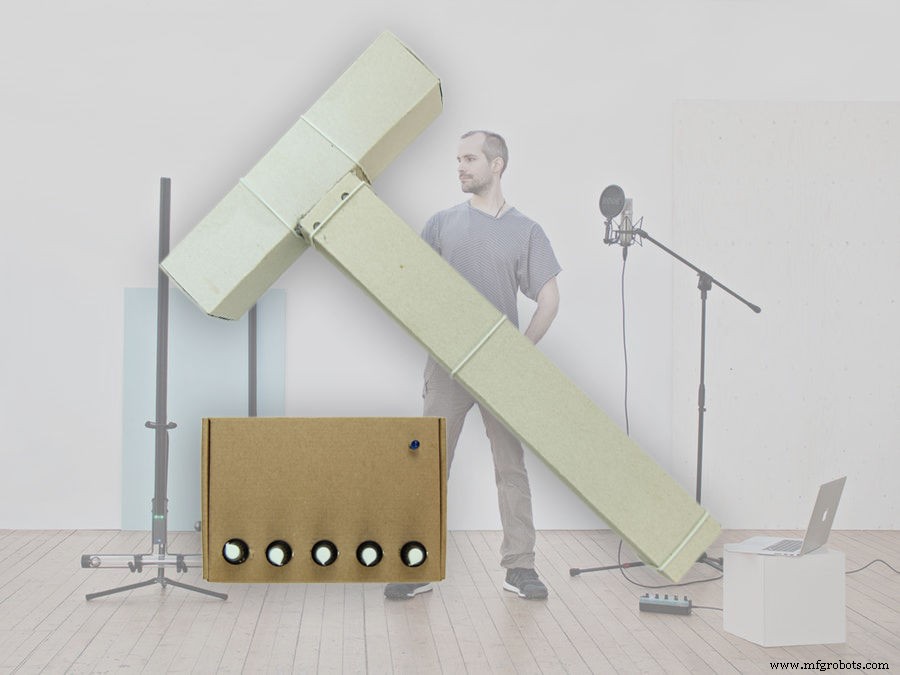
Kravox 的美妙之处在于它的形状、声音和演奏方式都可以调整。这让我有机会为本教程设计一个易于复制的 Kravox 版本。
(如果您好奇:在我的 youtube 频道上,您还可以找到我如何制作更大版本的 Kravox 的延时摄影)
上面的视频和本教程都将向您展示如何使用易于获得的电子元件和纸板构建功能齐全的控制器和接收器的所有必要步骤。
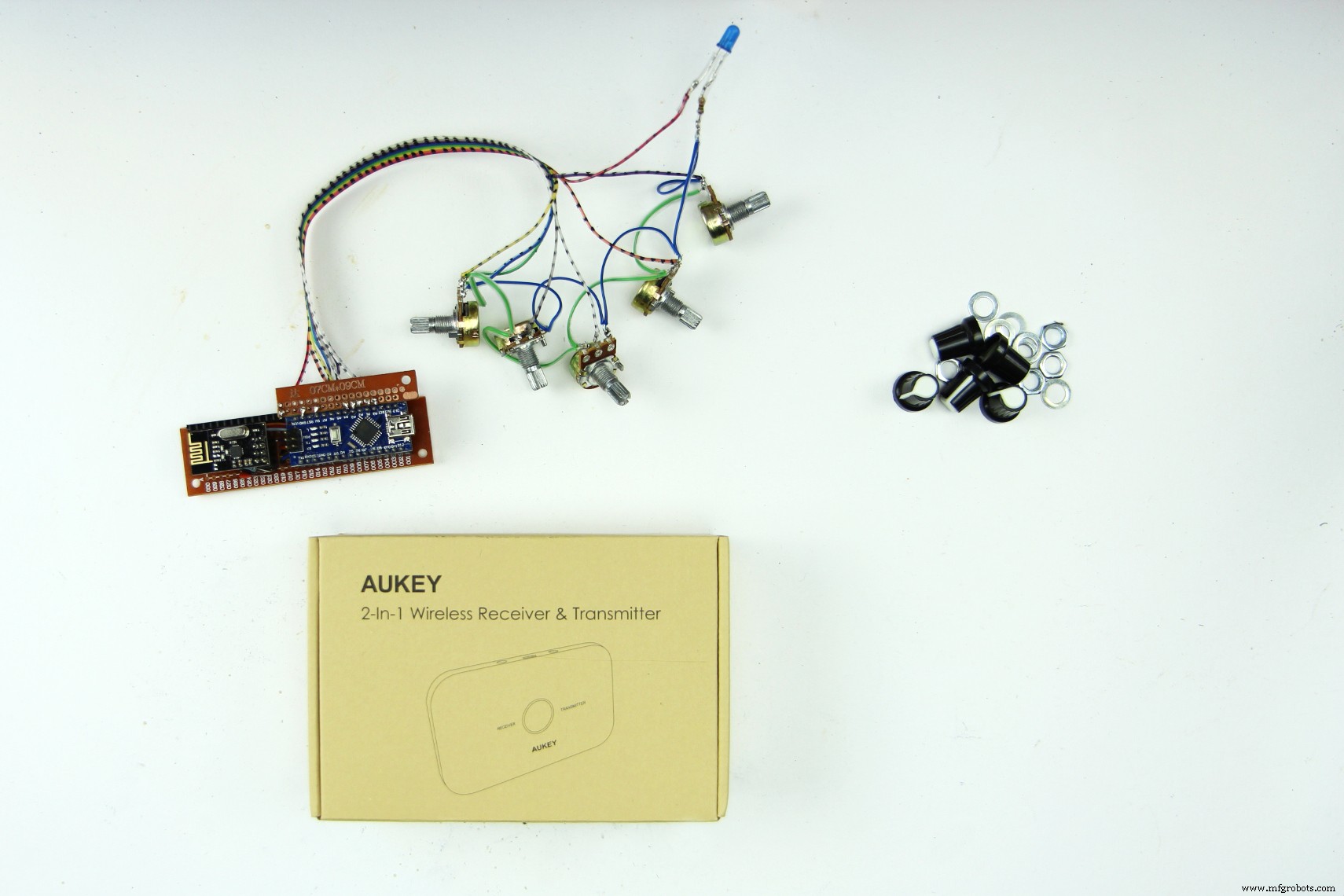
第 1 部分 - 收集组件和工具
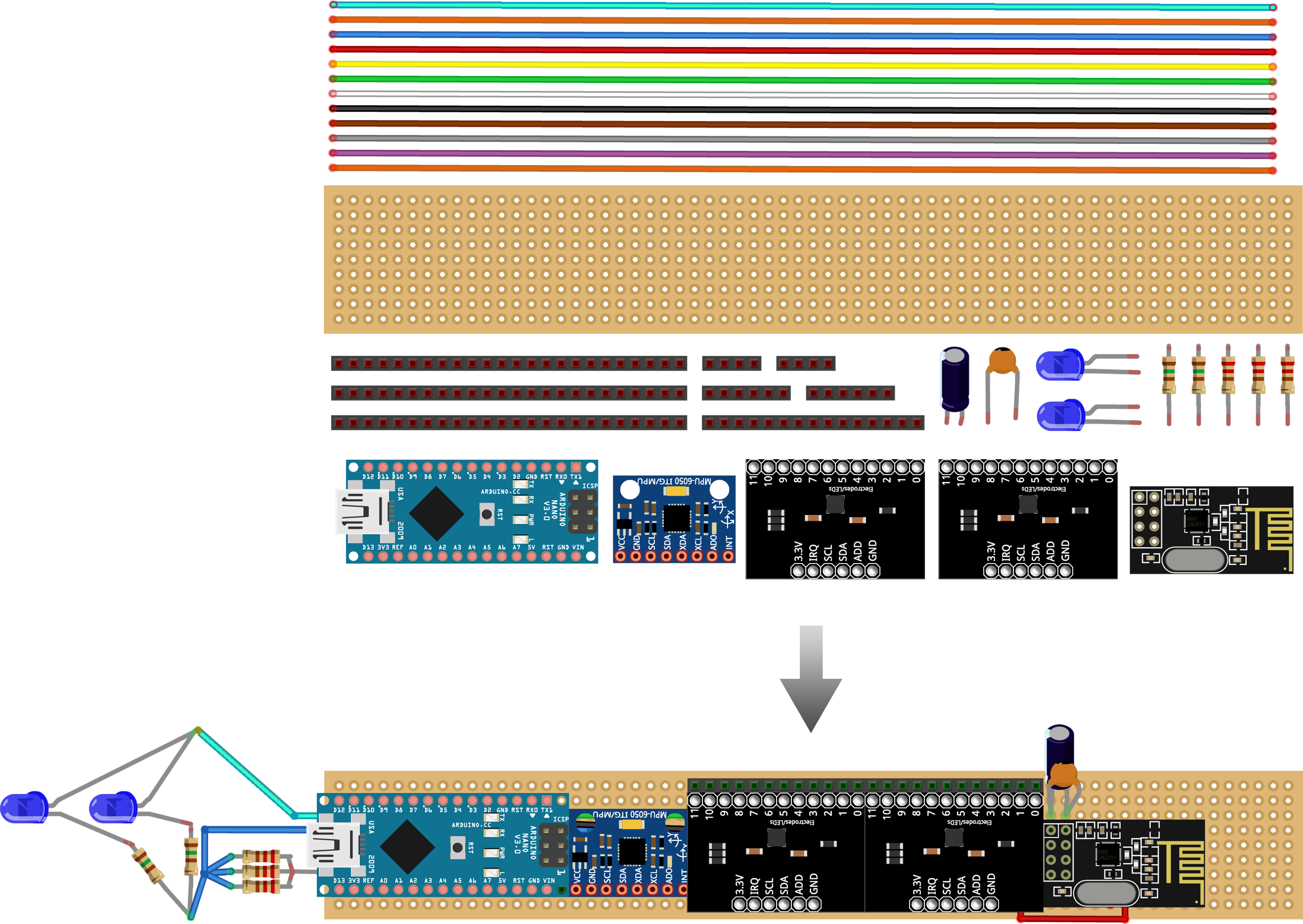
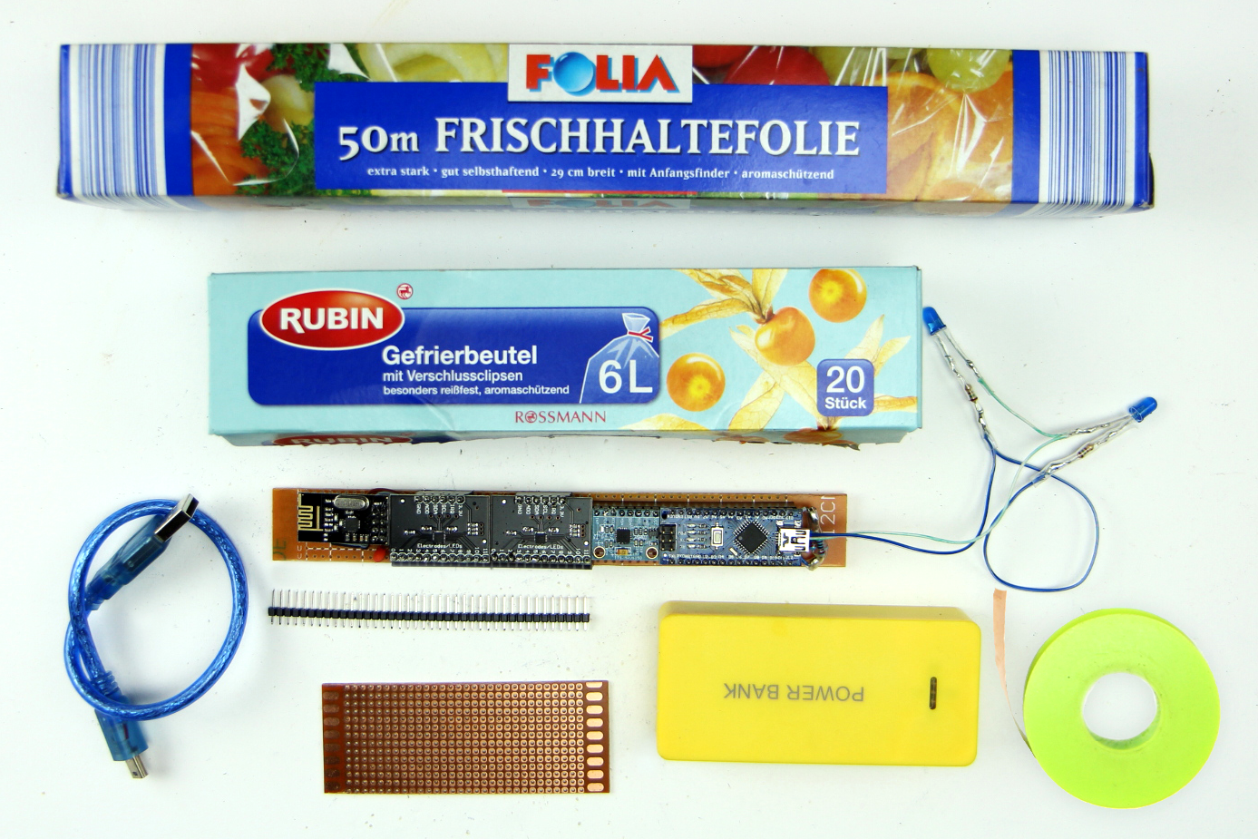
您将需要以下组件来构建 Kravox 控制器 + 接收器站:
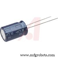
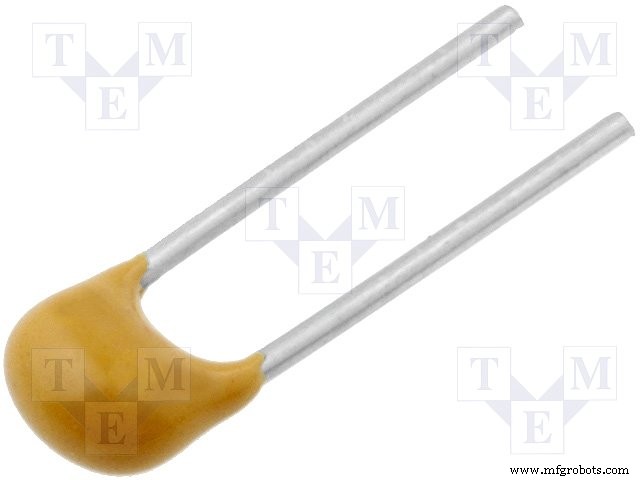
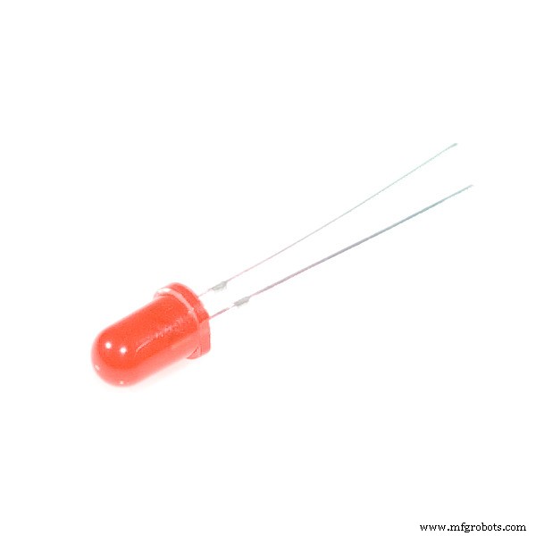
{1x} 50*24 孔(最小尺寸)穿孔板,{5x} 40 针母接头,{5x} 40 针公接头,{5x} 10 千欧电位器和旋钮,{3x} 蓝色 5 毫米标准LED、{3x} 150 欧姆电阻器、{2x} 10 微法拉电容器、{2x} 100 纳法拉电容器、{2x} NRF24L01 无线电收发器、{2x} Arduino nanos、{3x} 220 欧姆电阻器、{2x} MPR121 触摸传感器板、{1x} GY-521 MPU 6050 数字陀螺仪、{2x} USB-A 到 USB-C 电缆、{1x} 4 米(最少)1 厘米宽的铜带、{1x} 移动电源、{2x } 7 米(最少)线,多种颜色,可选 {1x} 0, 2 米 ø=3mm 收缩管。
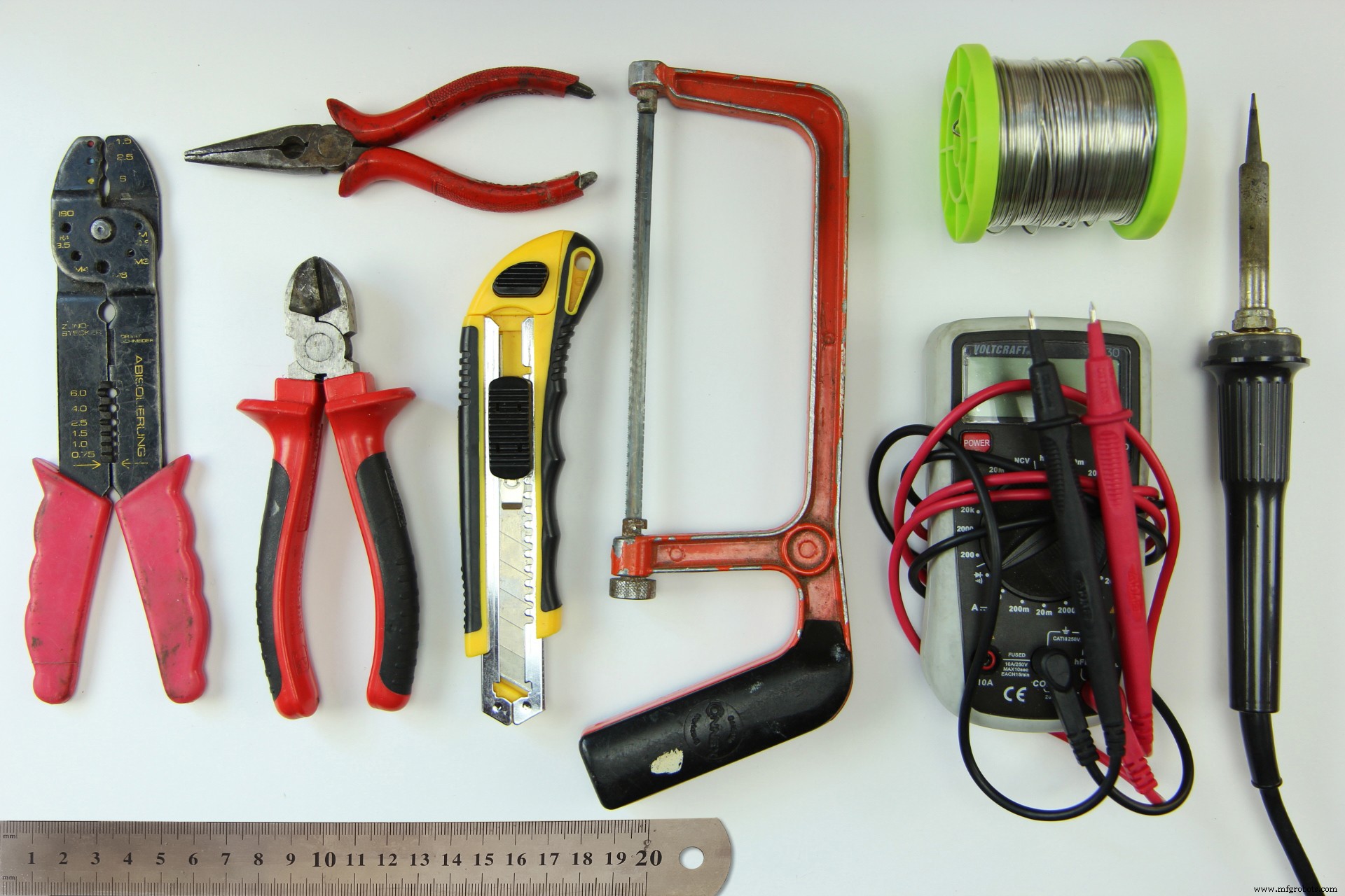
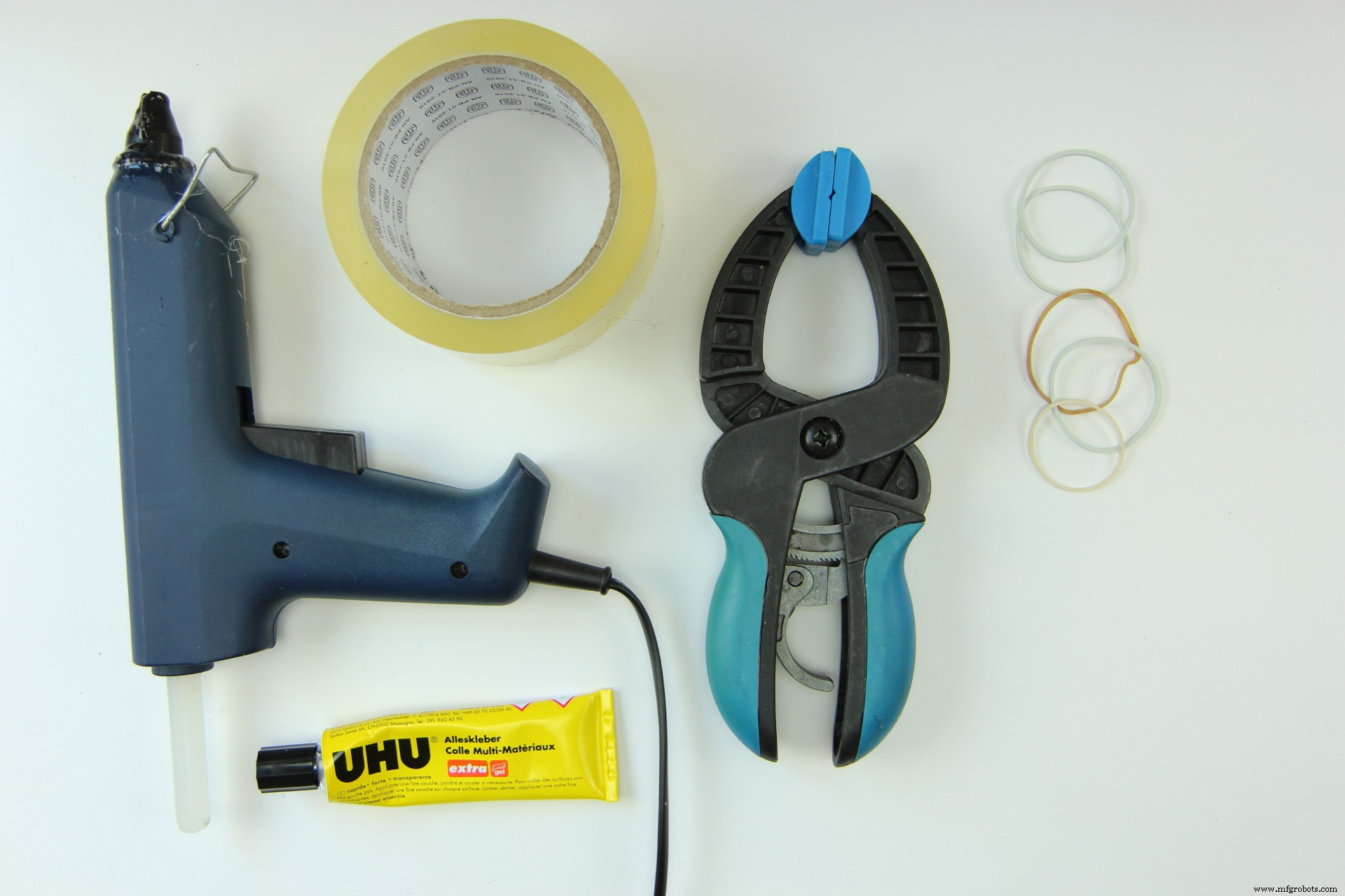
此外,您需要工具来组装组件:
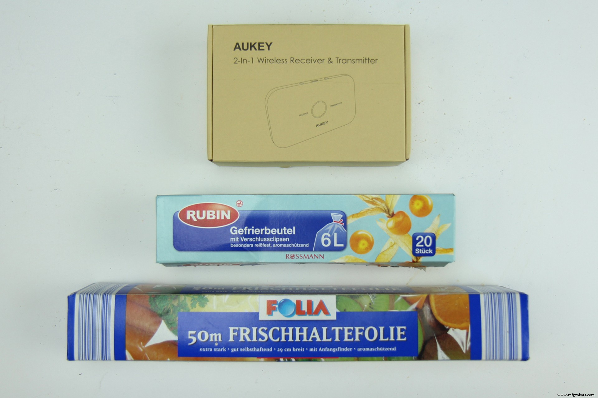
后来还有一些空纸板箱或类似的东西:
和胶水,胶枪,胶带,一个或多个夹子和橡皮筋来制作外壳:
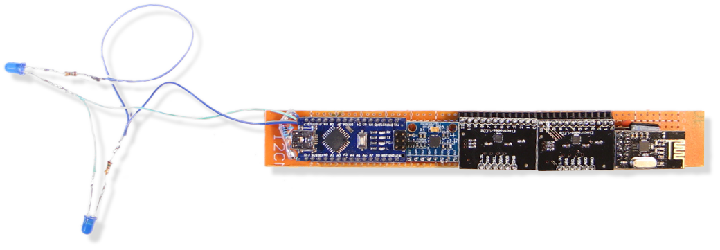
第 2 部分 - 制作控制器板
接下来我将从上面提到的部分逐步解释如何制作控制器电子元件
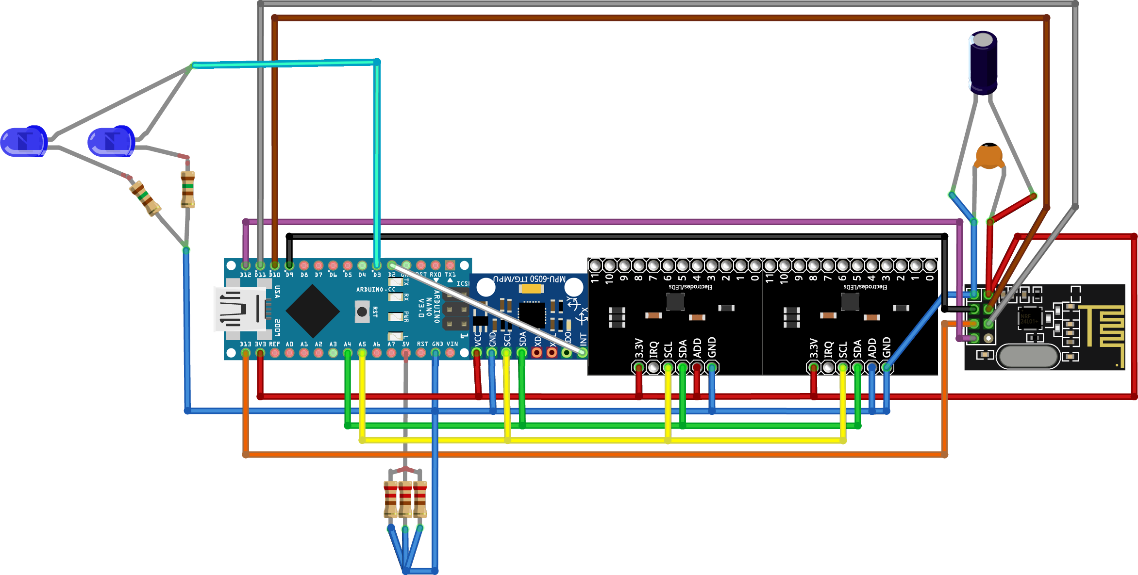
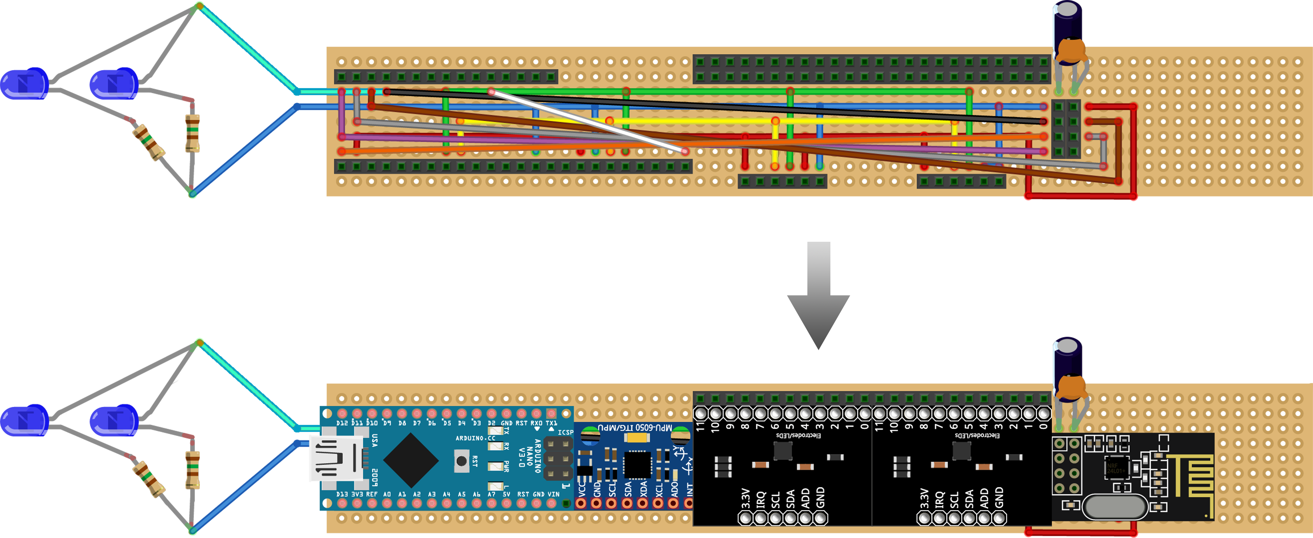
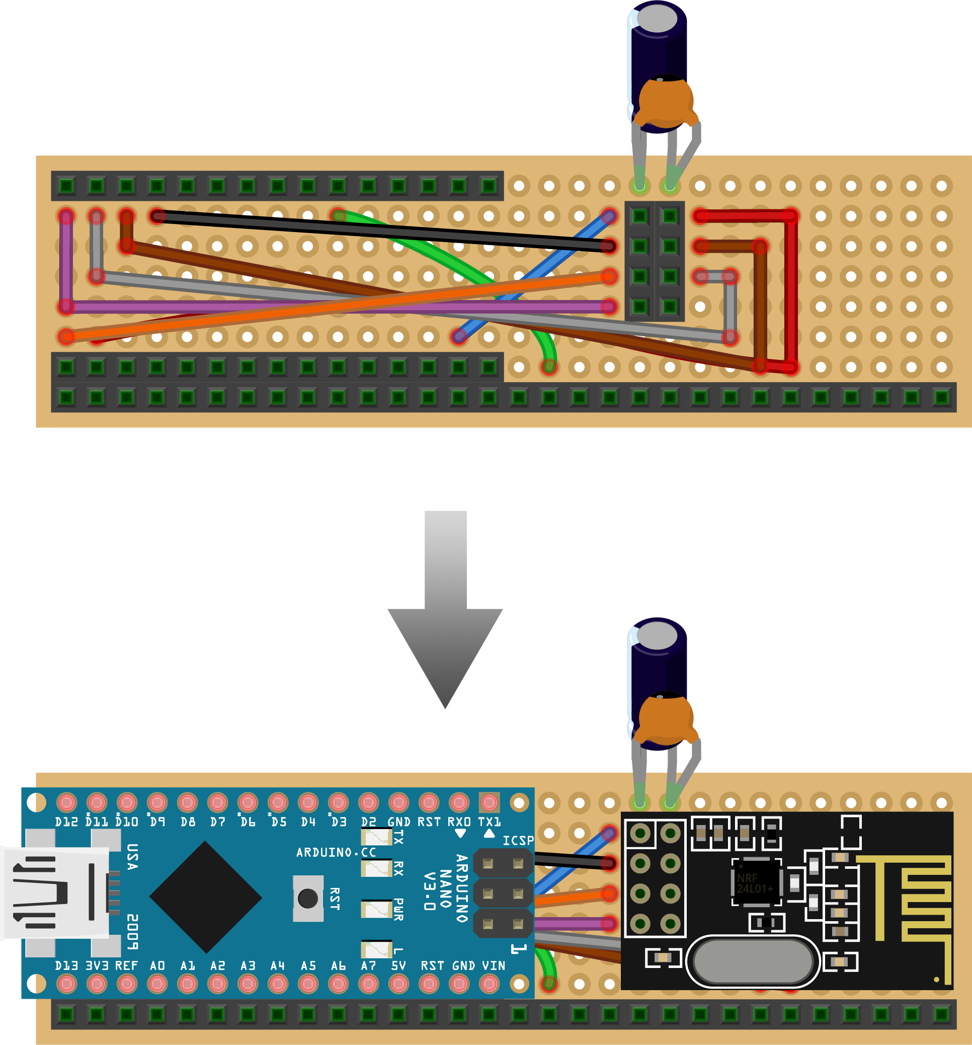
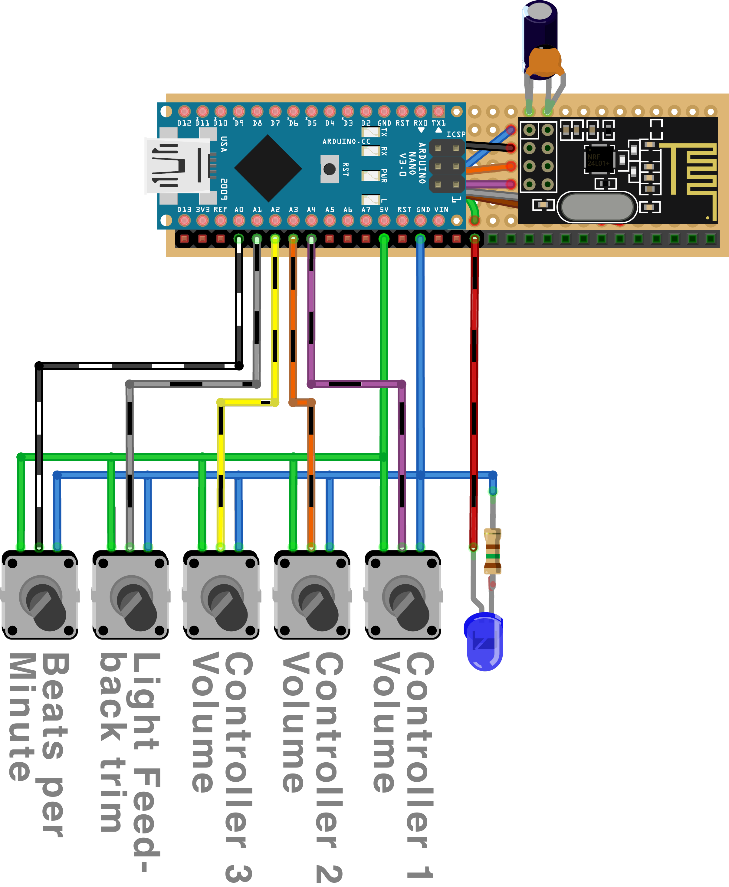
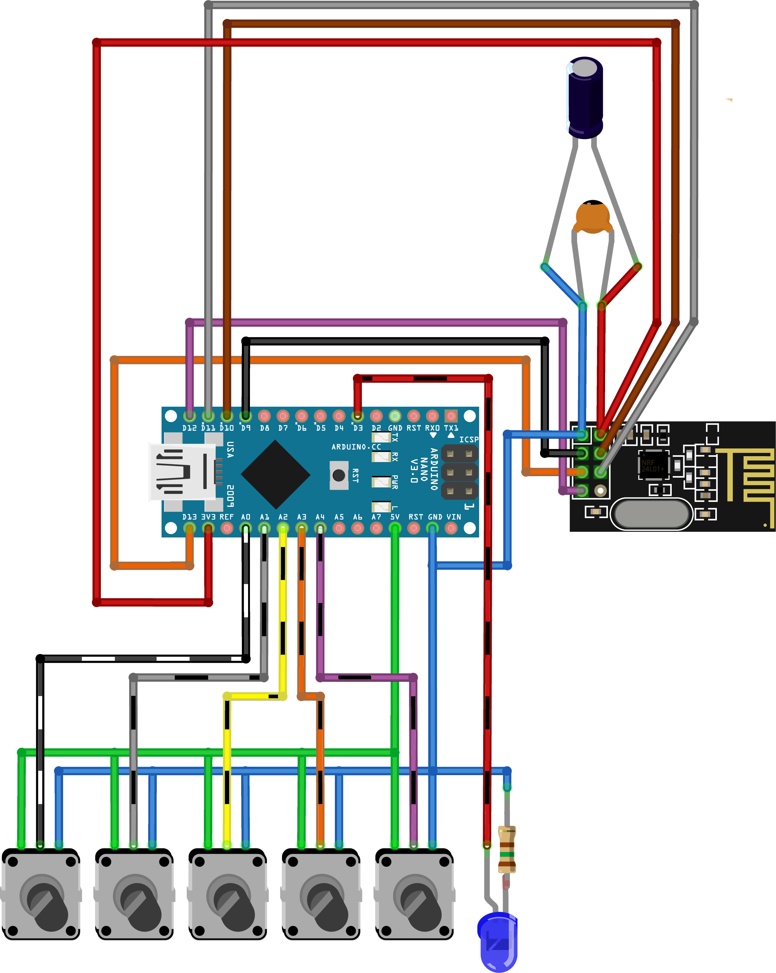
如果有疑问,在何处焊接电缆,您可以随时返回下面的电路图并检查组件是否正确连接,一旦您将 arduino 和传感器板连接到我们正在创建的电路板上。
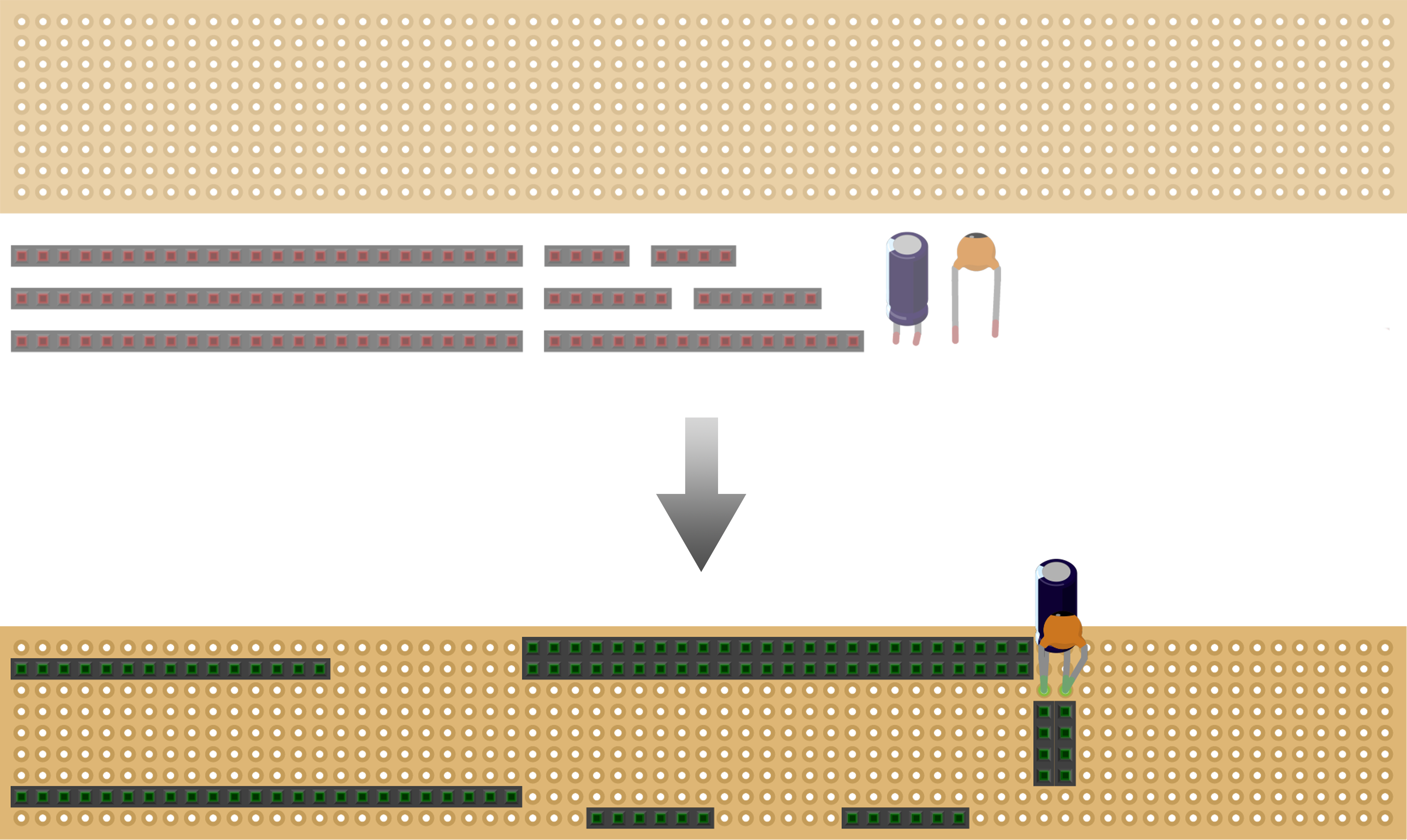
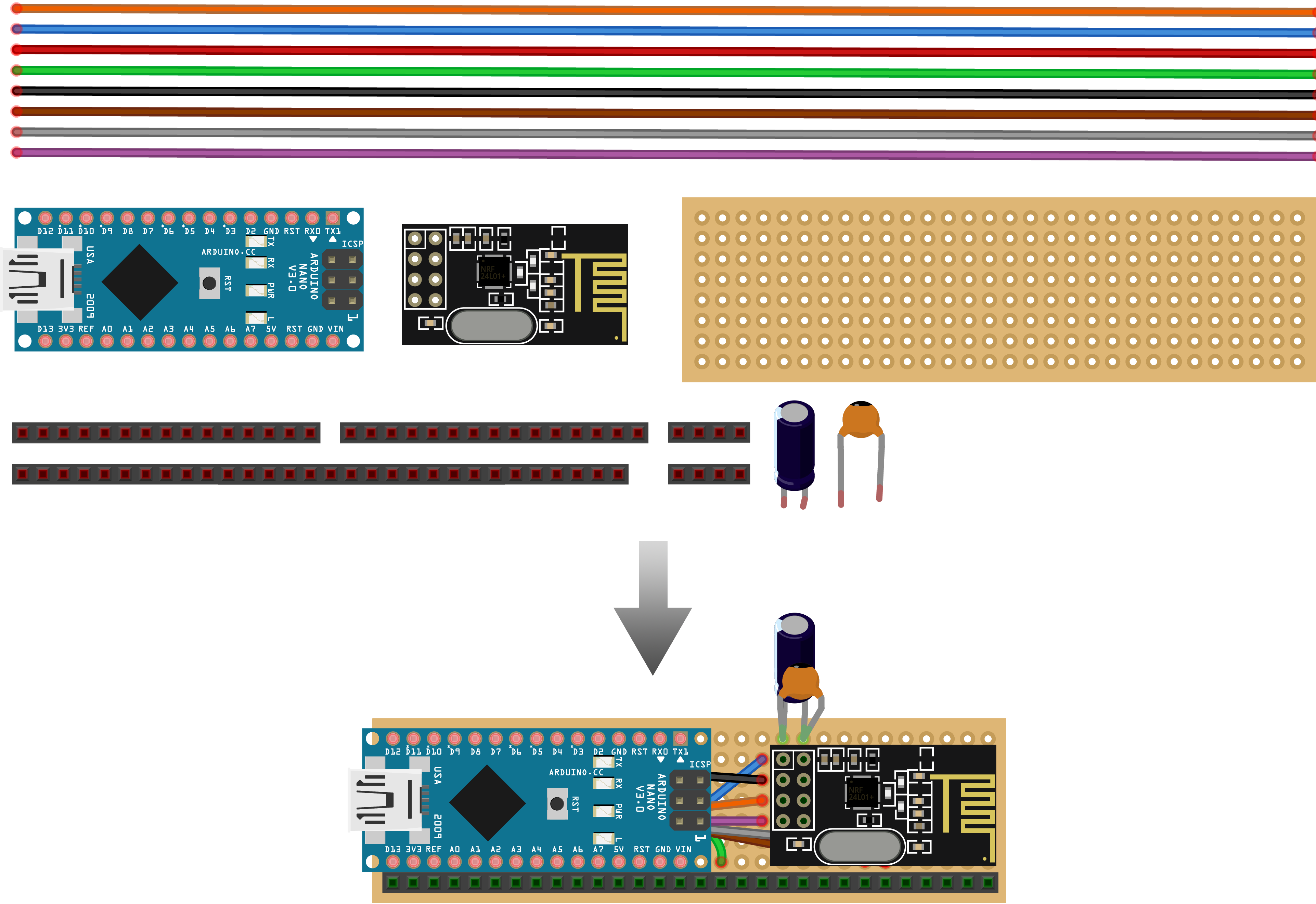
2.1
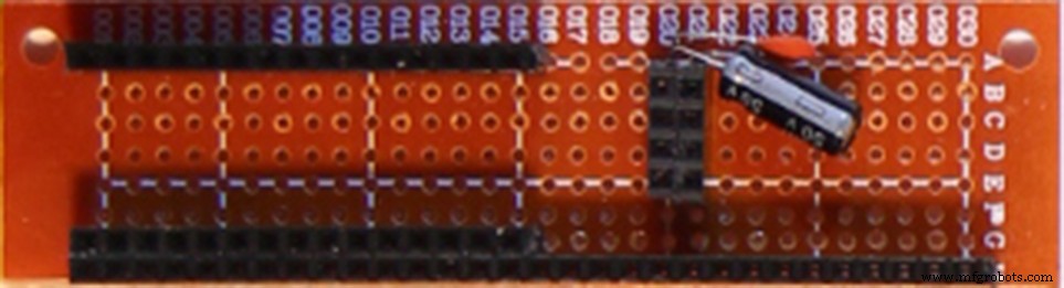
第一步是将穿孔板和母排针切割成一定尺寸,然后用一个大大小小的电容器将它们组装在一起,这有助于提高无线电收发器的可靠性:
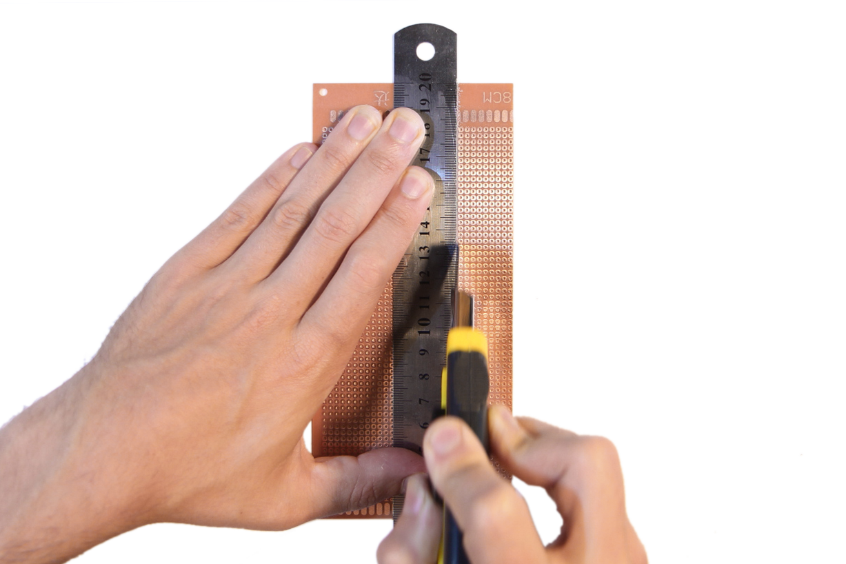
用美工刀切割穿孔板:
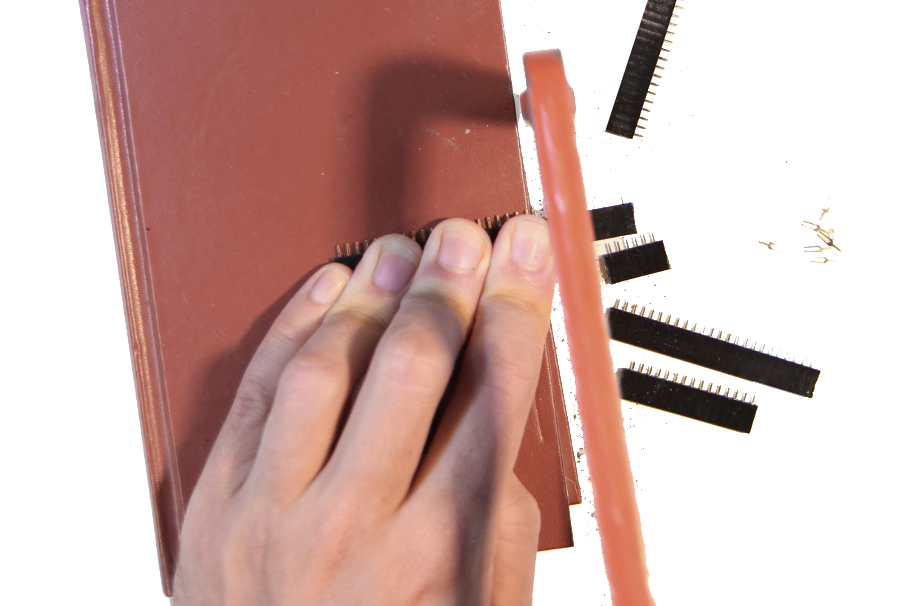
用钢锯切割母针头(我将它们放在书本上以将它们从桌面上调平):
焊接零件。您已经可以连接彼此相邻的两个长母头的每个引脚对。对于其余的接头,只需用一点焊料将它们连接起来就足够了 - 最好是根据电路图以后没有连接的引脚。焊接电容器时,请注意 10 微法拉电解电容器的极性(两者中较大的一个)。一侧会有条纹,通常还有较短的腿。那一边需要接地。较小的 100 纳法拉电容没有极化,可以任意焊接。
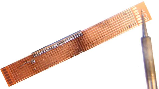
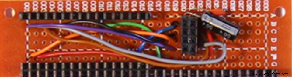
结果应该类似于:
2.2
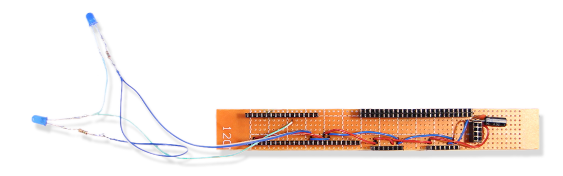
第二步是将两个LED和它们的限流电阻焊接起来。
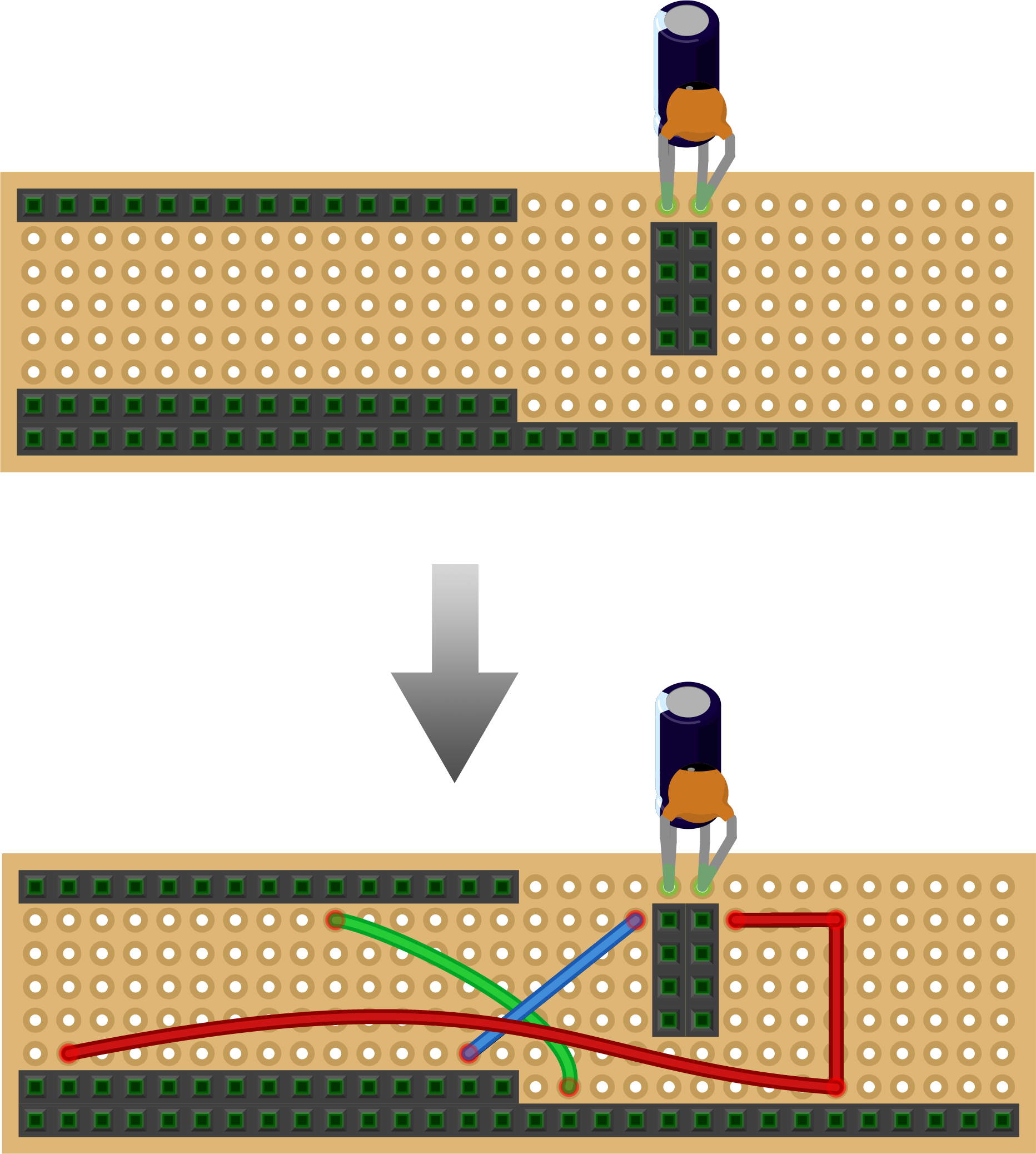
注意 LED 的极性:它的一侧是扁平的,通常也有较短的腿。该侧需要在步骤 2.3 中接地。在另一侧,我们现在将用青色电缆连接到插孔,稍后插入时 Arduino 引脚 D3 将位于该插孔:
2.3
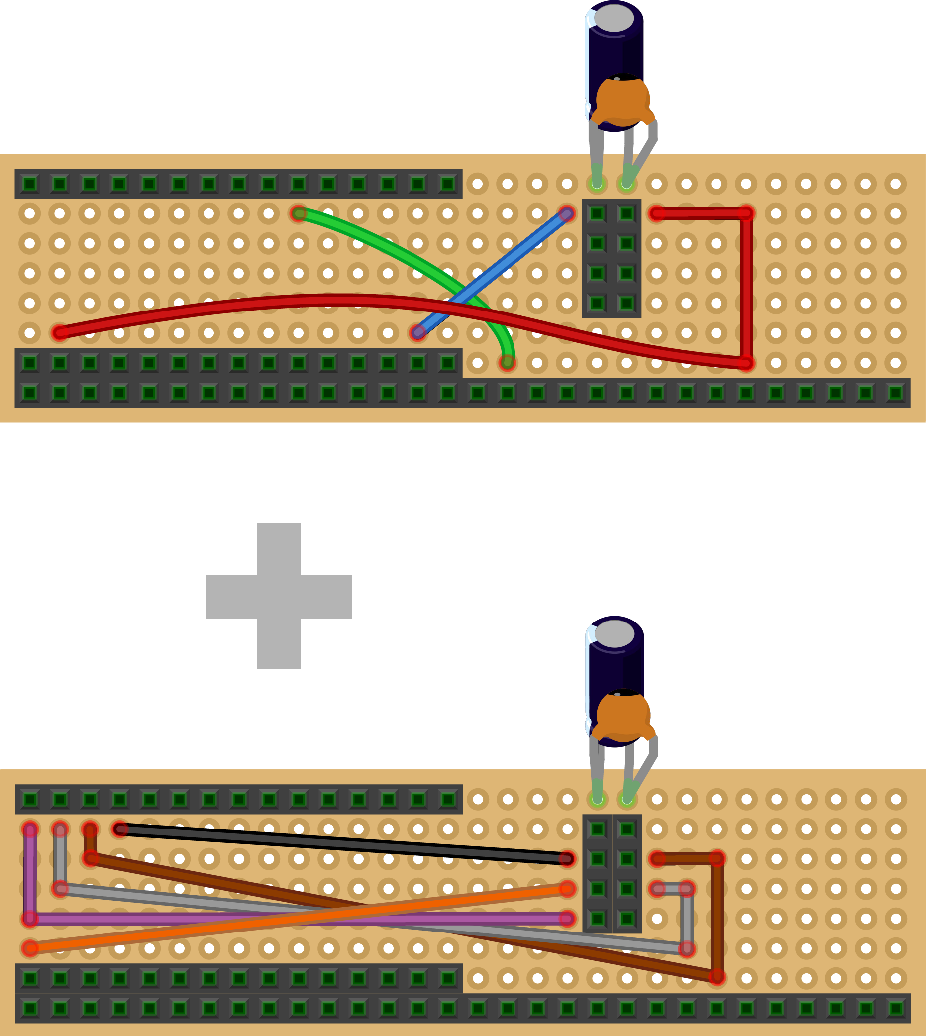
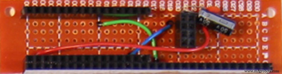
接下来我们添加所有红色和蓝色电源线。红色代表 3.3 伏,蓝色代表接地 (GND)
结果应该类似于:
2.4
到了第四步,棋盘上已经有些拥挤了。三个传感器板通过 I2C 协议(内部集成电路)进行通信。这意味着它们都可以连接到相同的两个 Arduino 引脚,因此我们在它们与 Arduino 引脚 A4 和 A5 之间焊接了黄色和绿色电缆。我们还为陀螺仪的中断引脚连接添加了一条白色电缆。
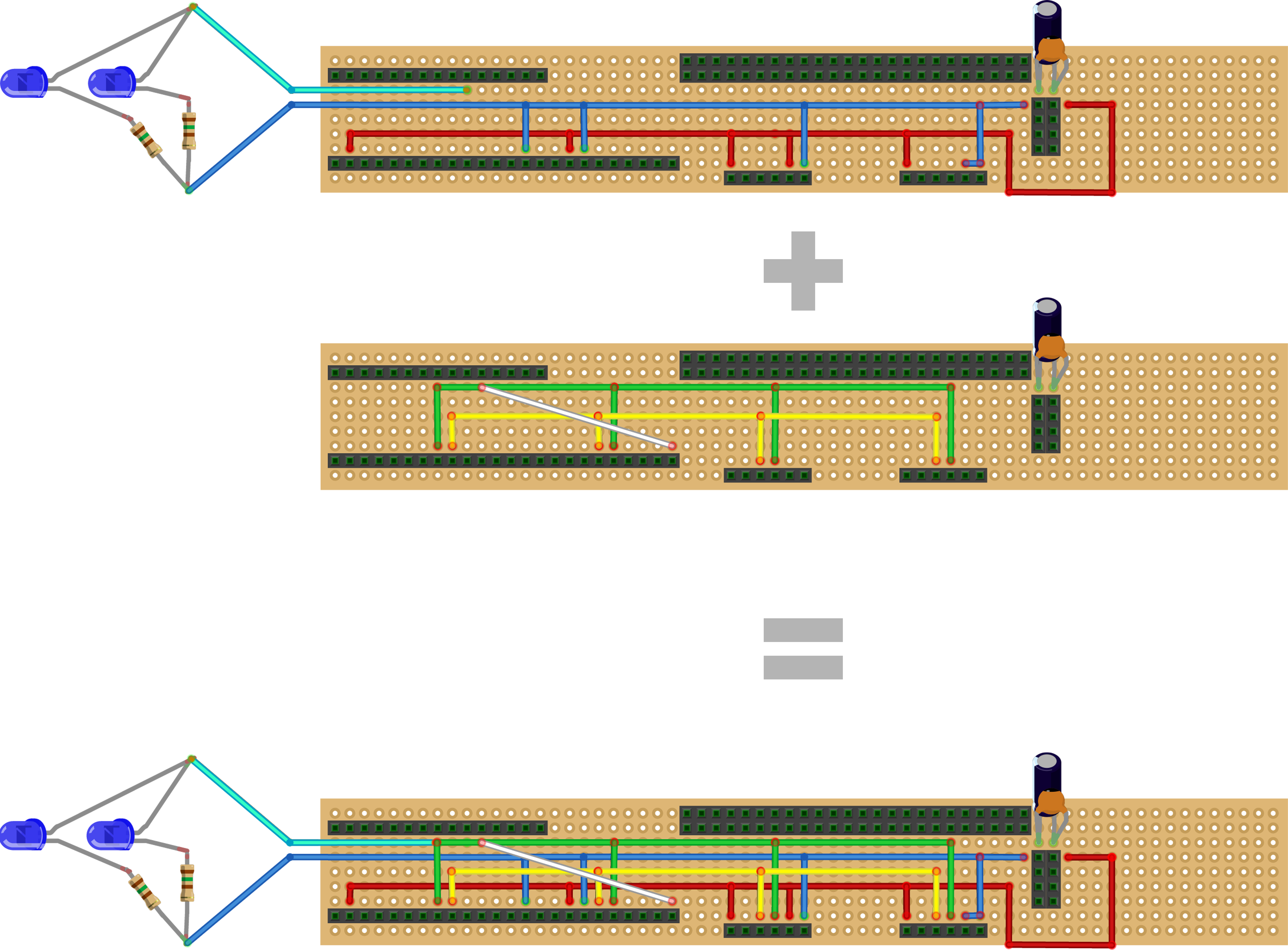
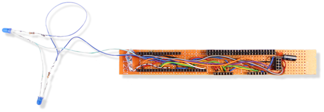
完成后,电路板看起来像这样:
2.5
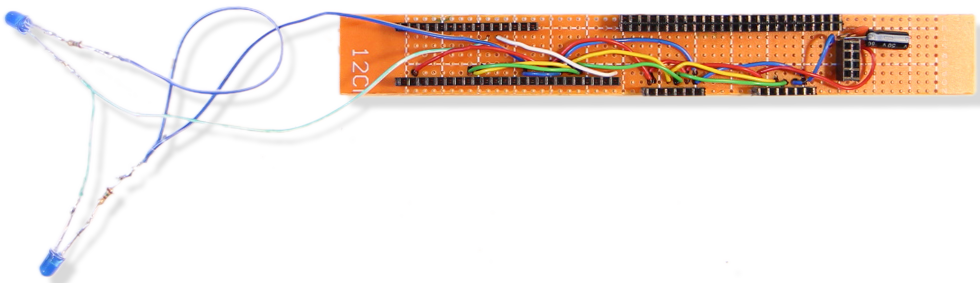
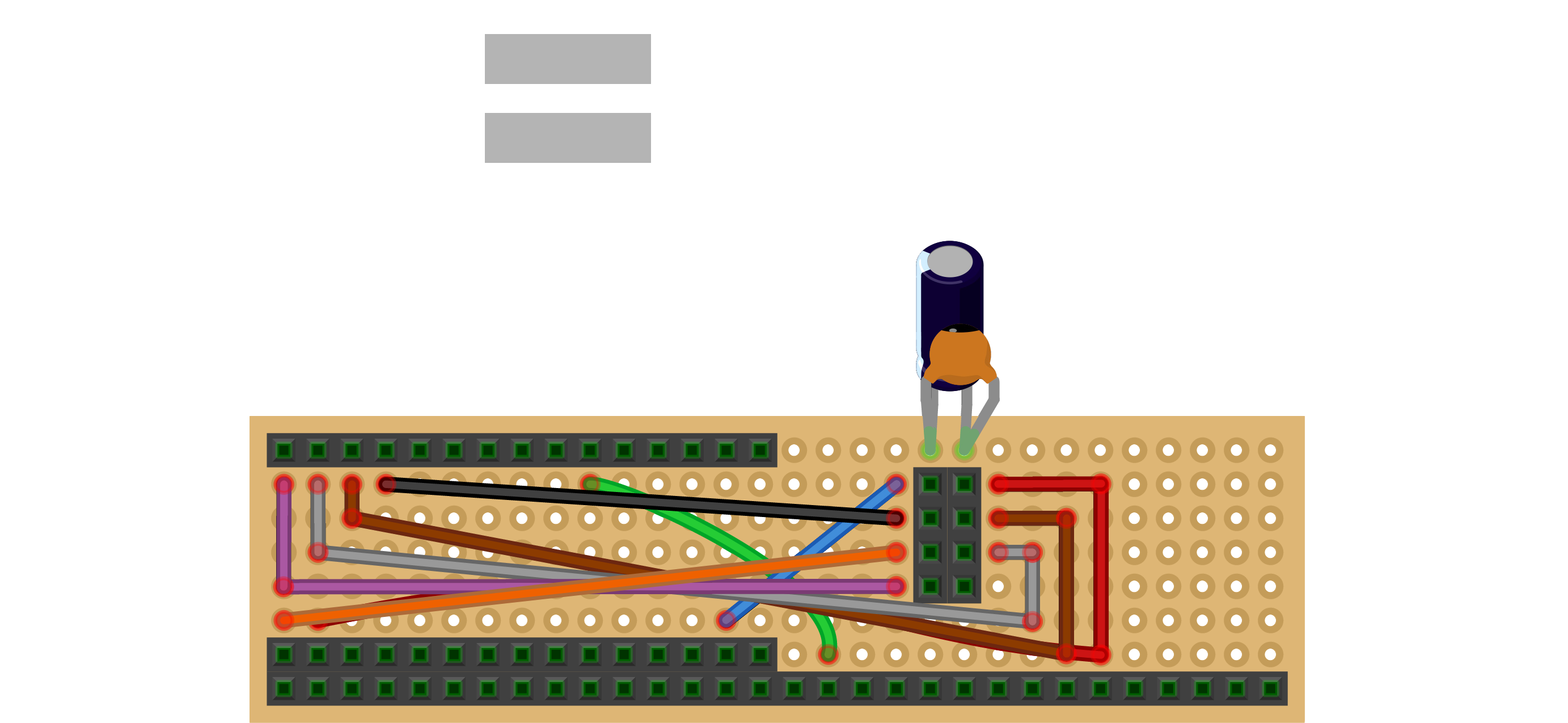
无线电收发器通过 SPI 协议(串行外设接口)进行通信,这比 I2C 需要更多的连接,因此我们添加了黑色、灰色、棕色、紫色和橙色电缆:
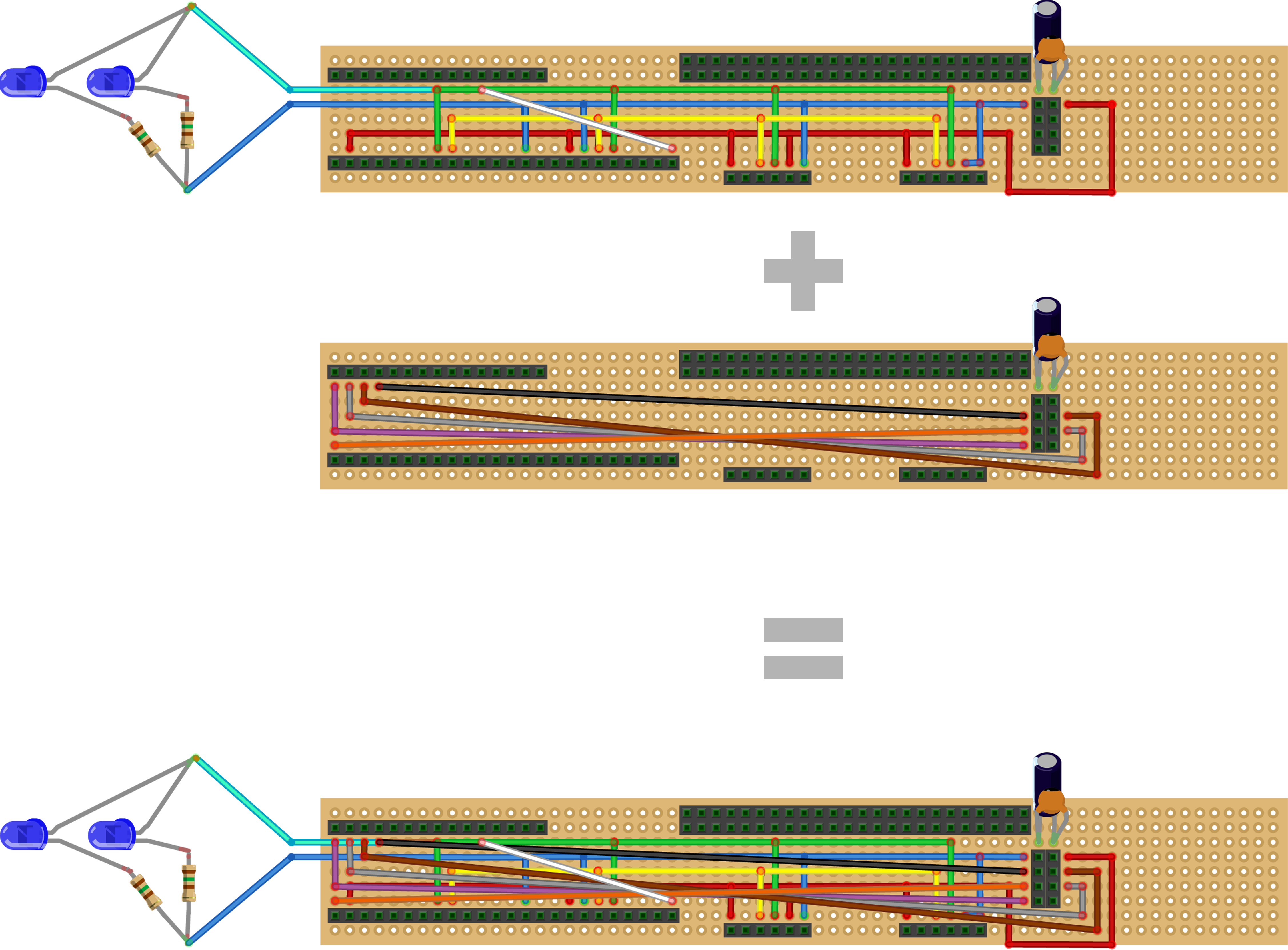
这就是你会得到的:
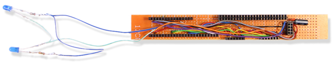
2.6
现在是准备组件的时候了。
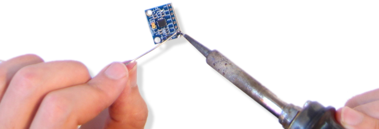
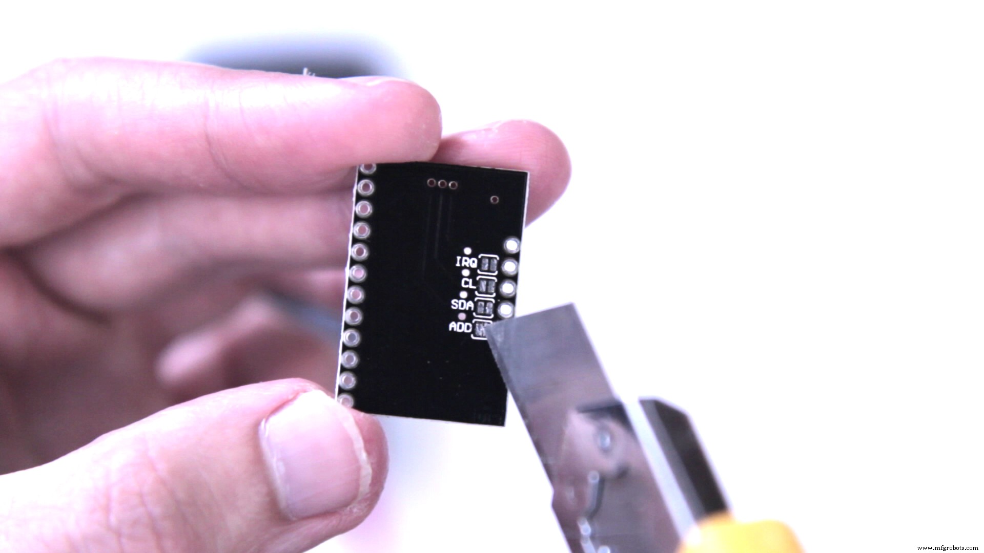
如果没有预焊接,除了焊接在公排针上之外,还要特别注意触摸传感器板!来自中国的廉价型号的地址引脚硬接线到地,中间没有下拉电阻,因此您需要用美工刀在电路板底部物理切断此连接。在写入 ADD 的位置旁边的两个焊盘之间切割。我建议使用万用表检查之后焊盘之间没有连接:
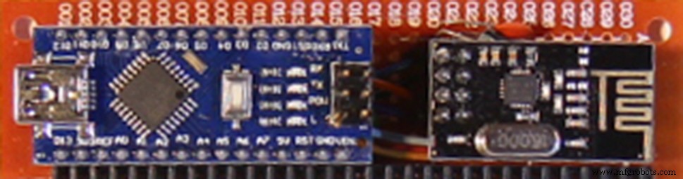
当所有组件都焊接好排针并准备好触摸传感器板后,您可以将 Arduino Nano、陀螺仪、两个触摸传感器板和无线电收发器插入控制器板:
(可能)完成的控制器板:
2.7
仔细检查后,如果一切都正确接线,下一步是将提供的 Kravox-Controller 代码(见附件)上传到 Arduino nano,但在此之前,您需要为陀螺仪安装库,触摸传感器板和无线电收发器。如果您不熟悉 Arduino 库,请在此处了解如何安装它们。
- MPU-6050 陀螺仪需要 Jeff Rowberg 提供的库“I2Cdev.h”和“MPU6050_6Axis_MotionApps20.h”,可在此处下载。
- MPR121 触摸传感器板需要 Bare Conductive 提供的“MPR121.h”库,可在此处找到。该库至少存在两个版本。确保安装 Bare Conductive 开发的版本,而不是 Adafruit 开发的版本。
- NRF24L01 无线电收发器板需要 TMRh20 提供的库“nRF24L01.h”和“RF24.h”,可在此处下载。请注意:这些库至少还存在两个版本相同的名称。确保安装由 TMRh20 开发的,而不是由 maniacbug 开发的。
一旦安装了库,您就可以上传 Kravox-Controller 代码。如果您已经想检查控制器是否正在工作,您可以让它通过串行监视器输出来自触摸传感器和陀螺仪的数据。为此,您需要取消注释 上传前接收者代码的最后一段:

通过删除开头 ( /* ) 和结尾 ( */ ) 的注释标记,代码如下所示:
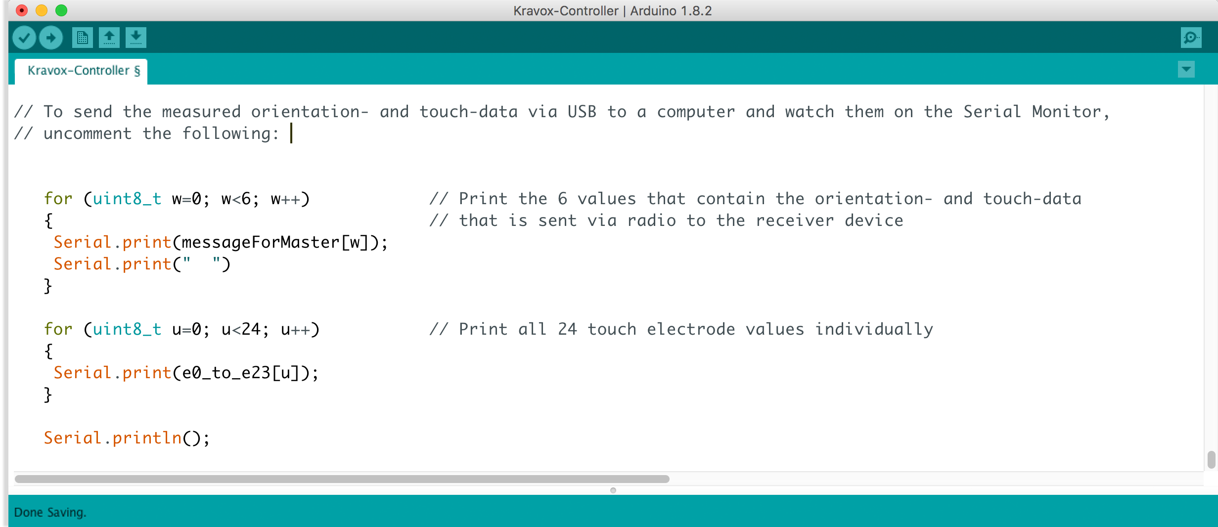
上传带有该变体的代码后,打开串行监视器,并将其设置为 115200 的波特率(数据传输速度)。现在您应该能够看到来自传感器的数据,当您移动控制器板并触摸引脚时会发生变化标记为 0 到 11 的 MPR121 板。
如果没有任何效果或您只得到零,请仔细检查您的接线并将其与上面的电路图进行比较。如果您从串行监视器获得有趣的输出,请检查您是否已将其设置为正确的波特率。
2.8
将您的控制器板连接到您要使用的移动电源。
如果板(或更准确地说是移动电源)在一段时间后没有自动关闭,则您的控制器板已完成,您可以继续第 3 部分!否则执行步骤 2.9
2.9
原则上控制板已经完成,但有些移动电源连接到控制板几秒钟后会自动关闭,就像现在这样,因为它消耗的能量很少
作为一个肮脏的修复,我们可以在 Arduino 的 5V 和 GND 引脚之间并联三个 220 欧姆的电阻器。这些电阻会消耗额外的能量并将它们转化为热量,因此控制器消耗的电量足以让移动电源保持工作状态。不用担心:即使有一个小移动电源,它仍然可以连续工作几天而无需充电
移除 Arduino Nano 并像这样焊接电阻:

所以板子看起来像这样:
重新连接组件后,(绝对)完成的控制器板看起来像这样:
第 3 部分 - 制作接收器板
在教程的这一部分中,我将向您展示如何制作接收器板。这个过程与制作控制器板非常相似
如果你想检查,某根电缆应该连接到哪里,你可以参考这个电路图:
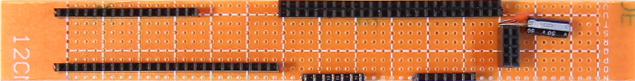
3.1
第一步是再次将穿孔板和母排针切割成一定尺寸,然后将它们与一个大小不一的电容器组装在一起,这有助于提高无线电收发器的可靠性。最低的母排针故意留得比必要的长,因此您可以稍后将其用于其他项目,例如 Arduino 颗粒合成器。您可以将此步骤与步骤 2.1 进行比较以获取更多信息
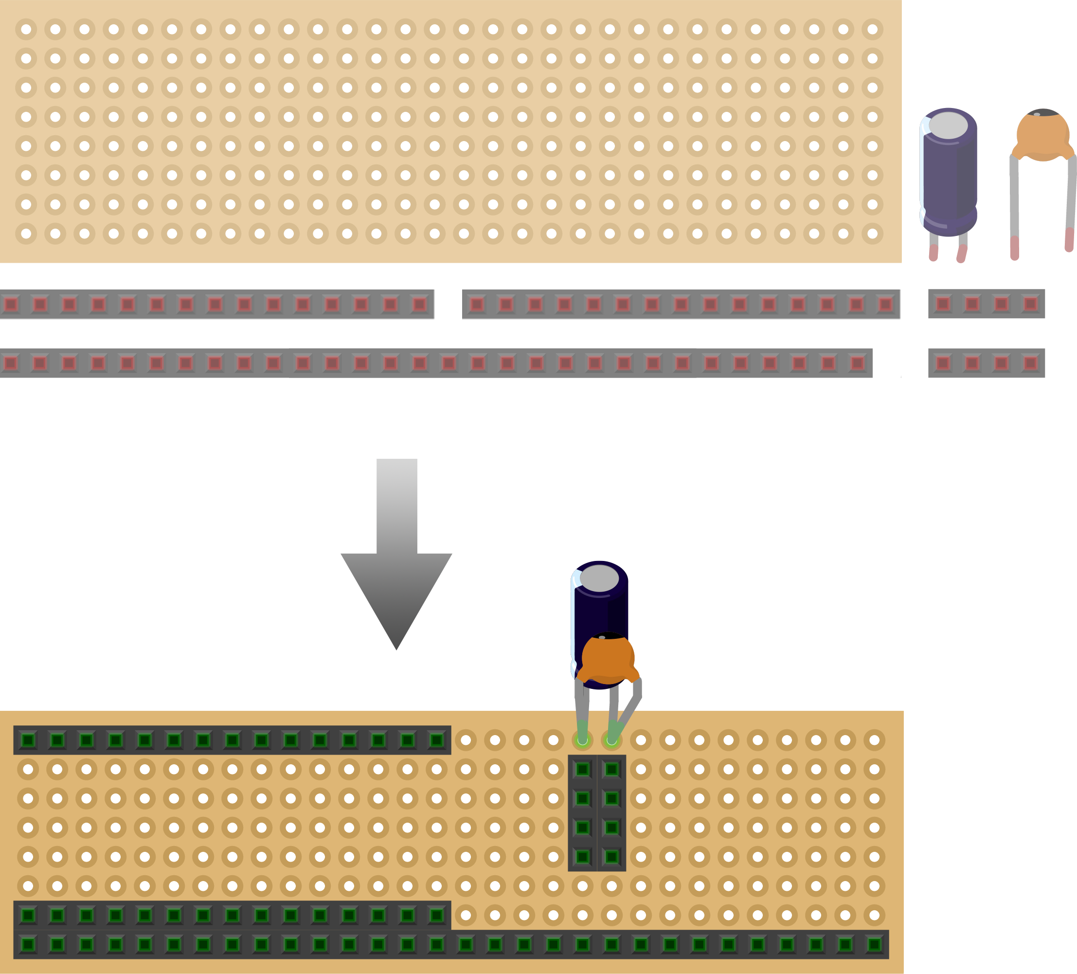
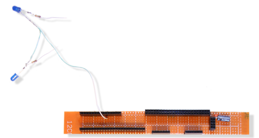
步骤 3.1 末尾的电路板照片:
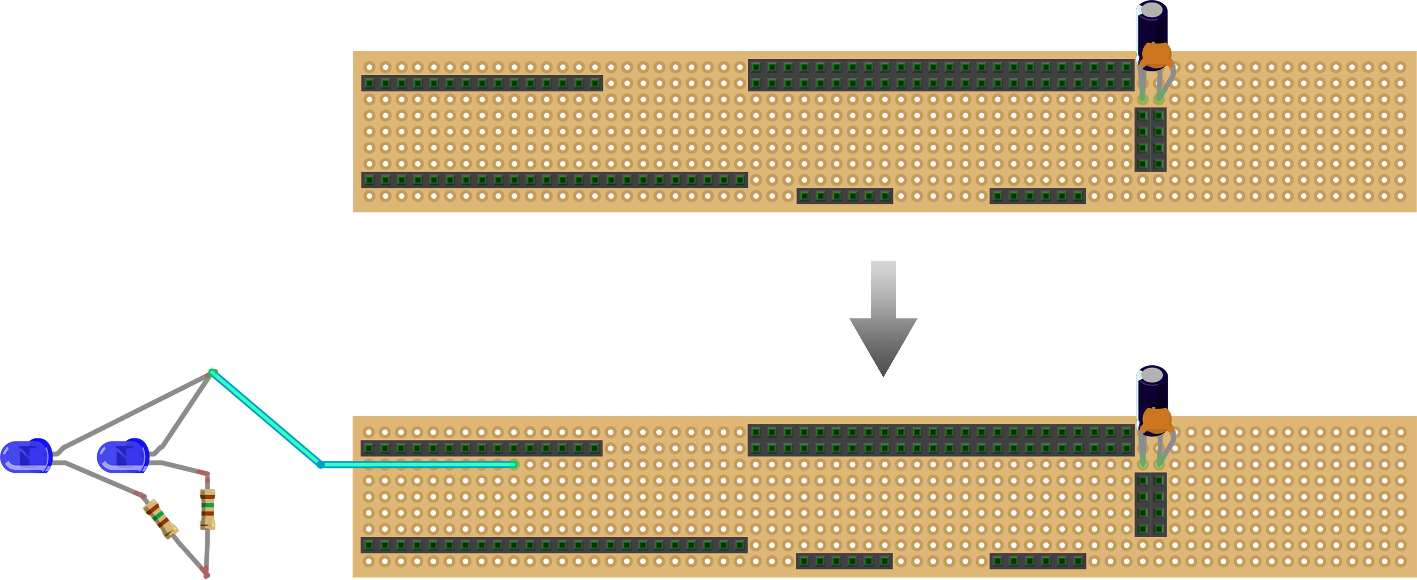
3.2
接下来我们添加所有红色和蓝色电源线。红色代表 3.3 伏,蓝色代表接地 (GND)
它应该是这样的:
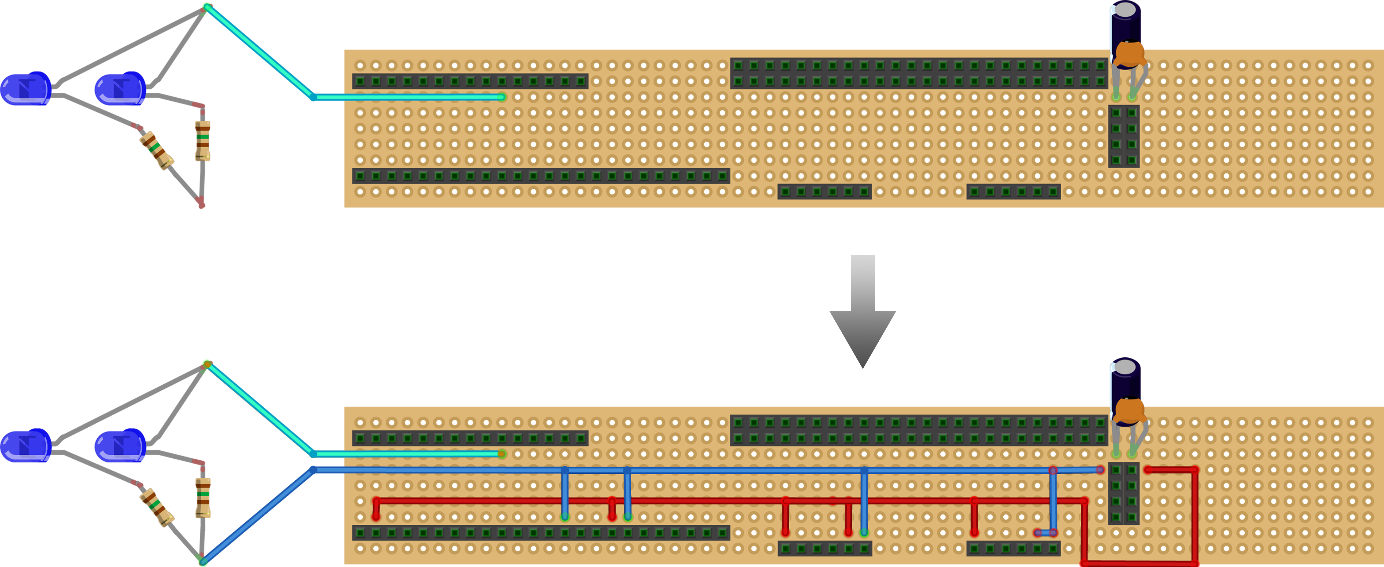
3.3
焊接在用于 SPI 通信的电缆中:
3.4
附加组件:
接收器板现在已经完成,但是在我们将附件中的 Kravox-Receiver 代码上传到 Arduino Nano 之前,我们首先需要为接收器制作一个接口
第 4 部分 - 制作接收器接口
在教程的这一部分中,我将向您展示如何使用 4 个电位计和一个 LED 为接收器制作接口。接口是这样接线的:
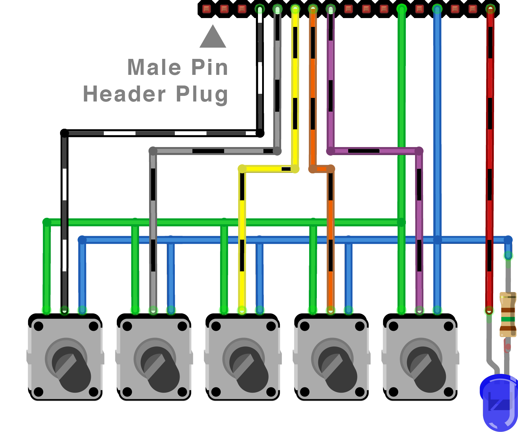
并将像这样插入接收器板:
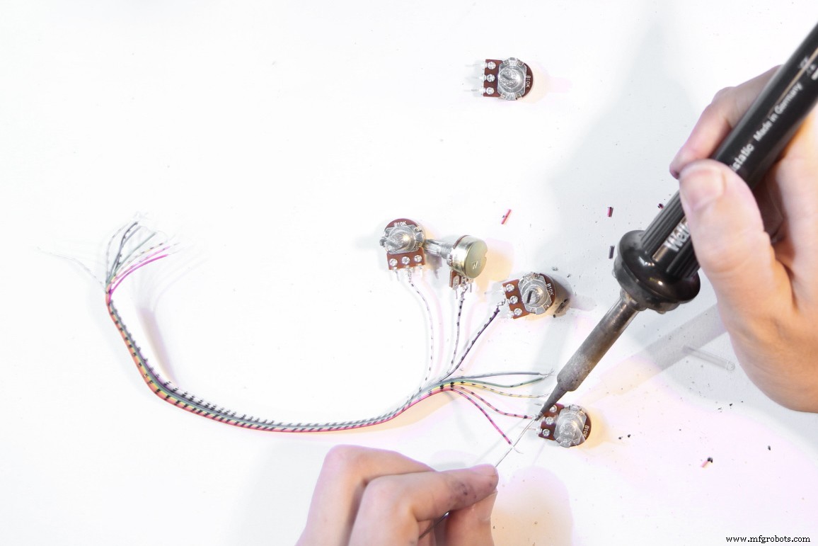
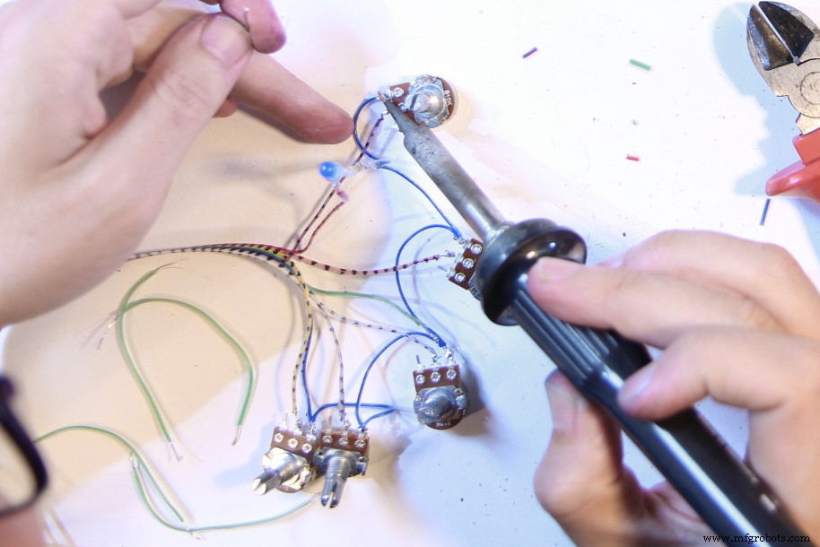
像这样进行:首先取一根由 8 根电缆组成的线束,并将其中的 5 根焊接到电位器的中间引脚上。最好使用相同的颜色以免混淆:
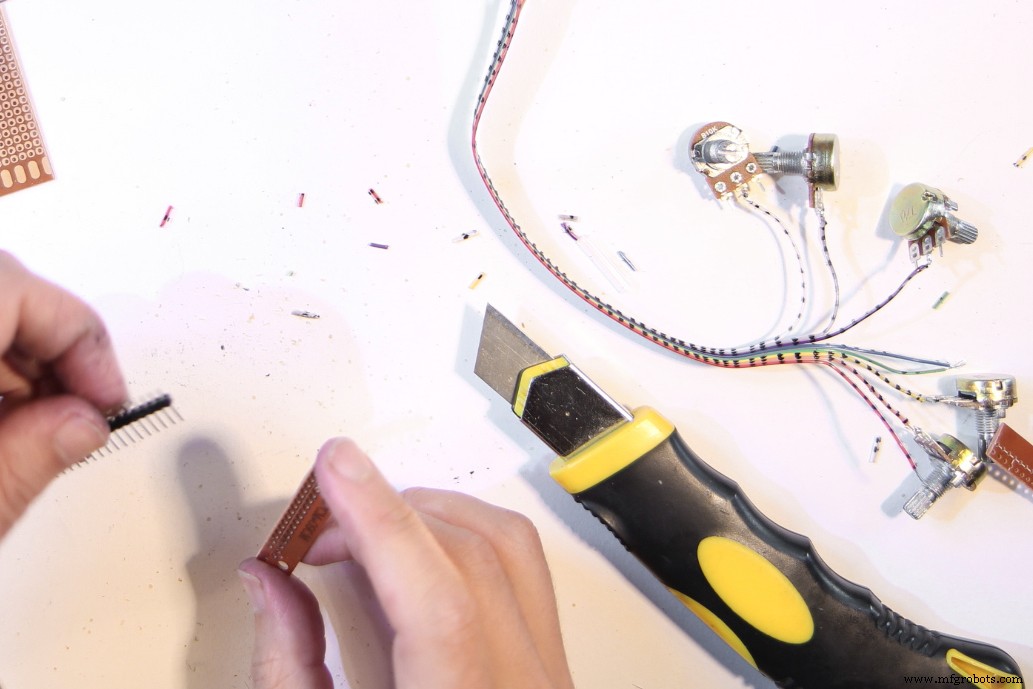
接下来,切割一个2 * 17孔宽的穿孔板和一个17针公排针的尺寸
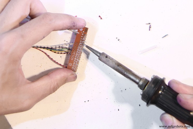
将电缆和排针连接到电路板上。请注意上面的电路图以确保将电缆连接在正确的位置
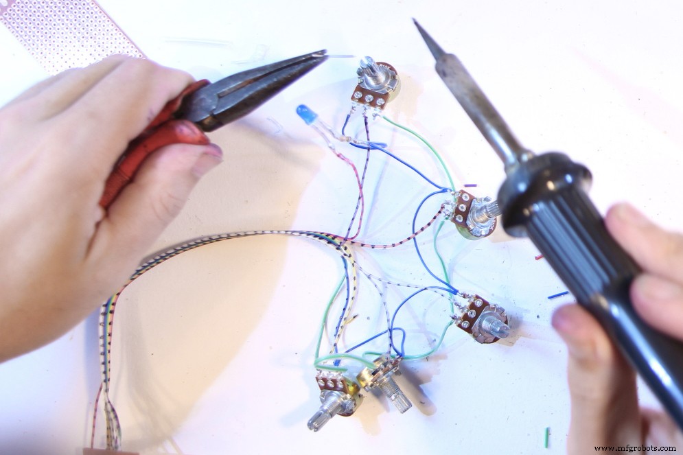
现在用蓝色接地电缆连接所有电位计的一侧(也许使用比我做的稍长的电缆)。还要添加带有 150 欧姆限流电阻的蓝色 LED。再次注意 LED 的极性(对比步骤 2.2)
接下来用绿色的 5V 连接电缆连接所有电位器的另一端(可能使用比我做的稍长的电缆)。
完成后的界面应该是这样的...
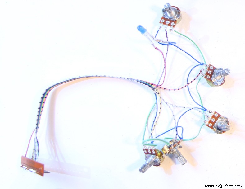
...and can be plugged into the receiver board like that:
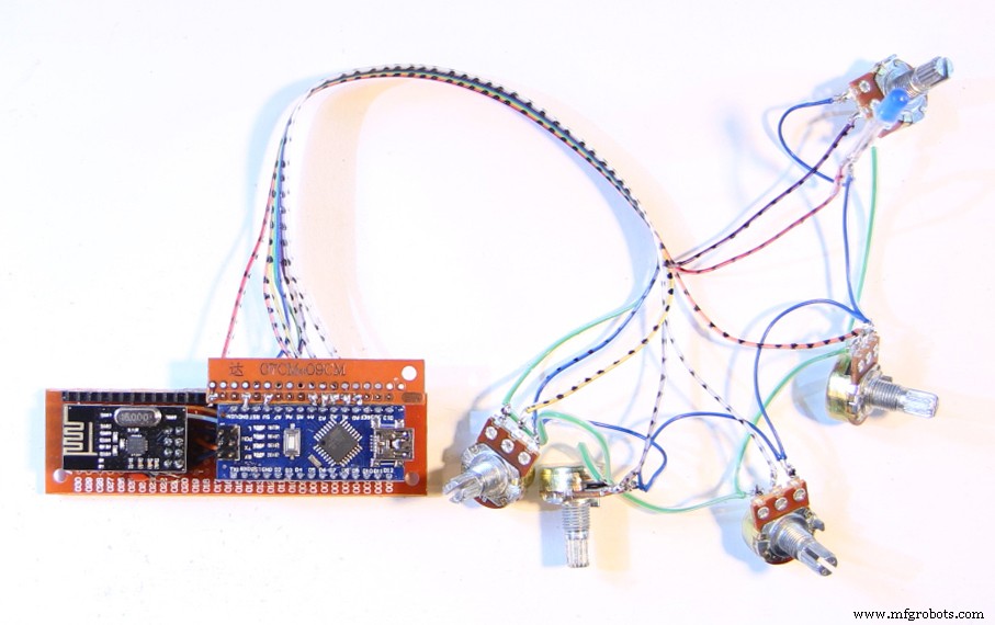
Now you can also upload the Kravox Receiver code to the receiver's Arduino Nano.
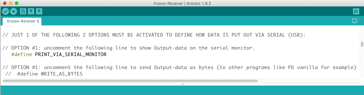
If you want to see if it is working and receiving data from the controller, you again need to make a slight adjustment to the code before uploading. By default the Receiver will output it's data in a format that can be interpreted by pure data, but will not show useful information on the Serial Monitor. However you can change this behaviour in the code by commenting (adding // in front of) the line that says:
#define WRITE_AS_BYTES
and uncommenting (removing // in front of) the line that says:
// #define PRINT_VIA_SERIAL_MONITOR
So you turn this:
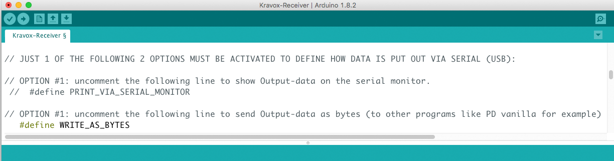
into that:
After uploading the altered code you will be able to see data from the controller and 4 of the potentiometers on the Serial Monitor as I demonstrate in this video:
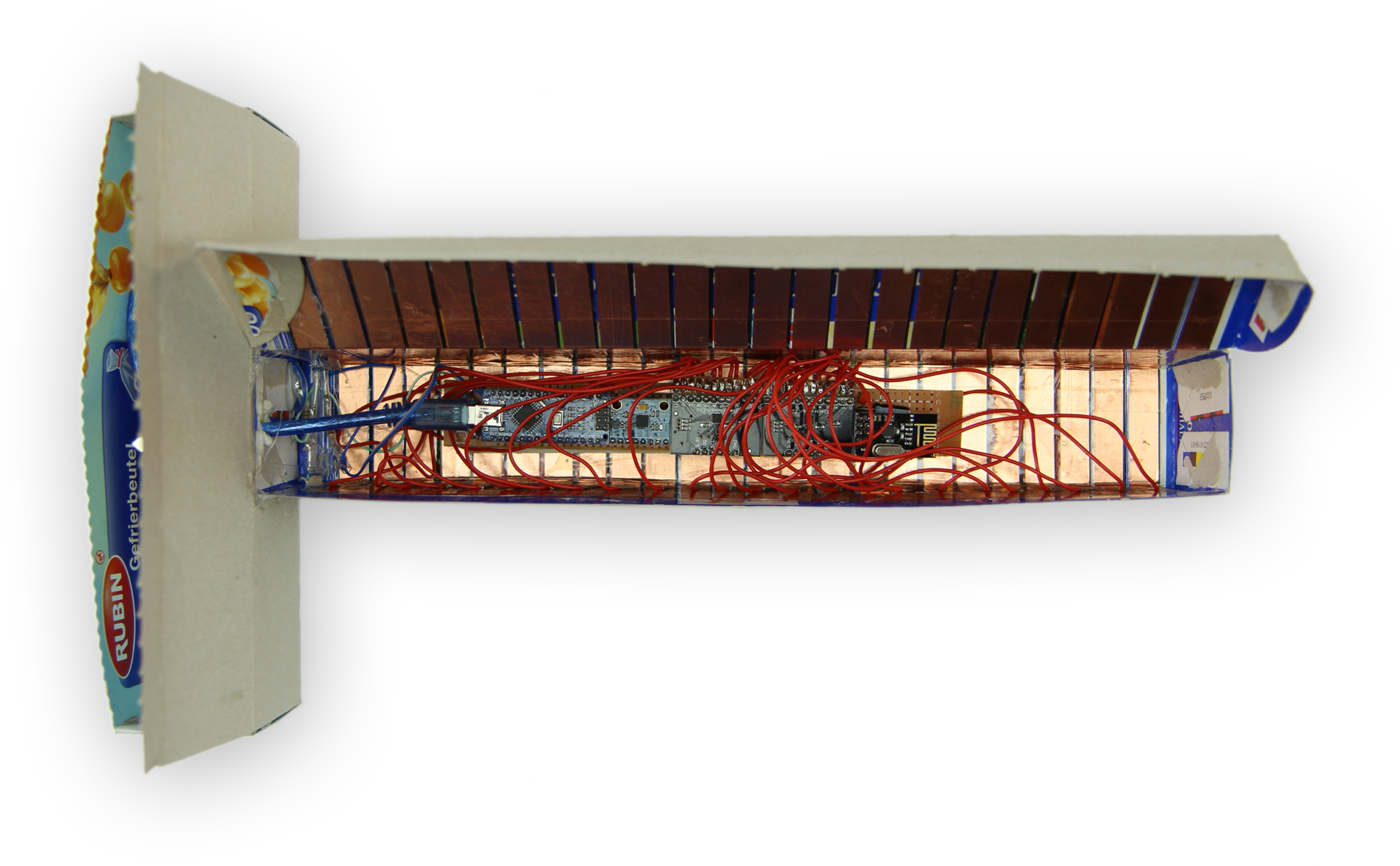
Part 5 – Making the Controller Interface + Enclosure
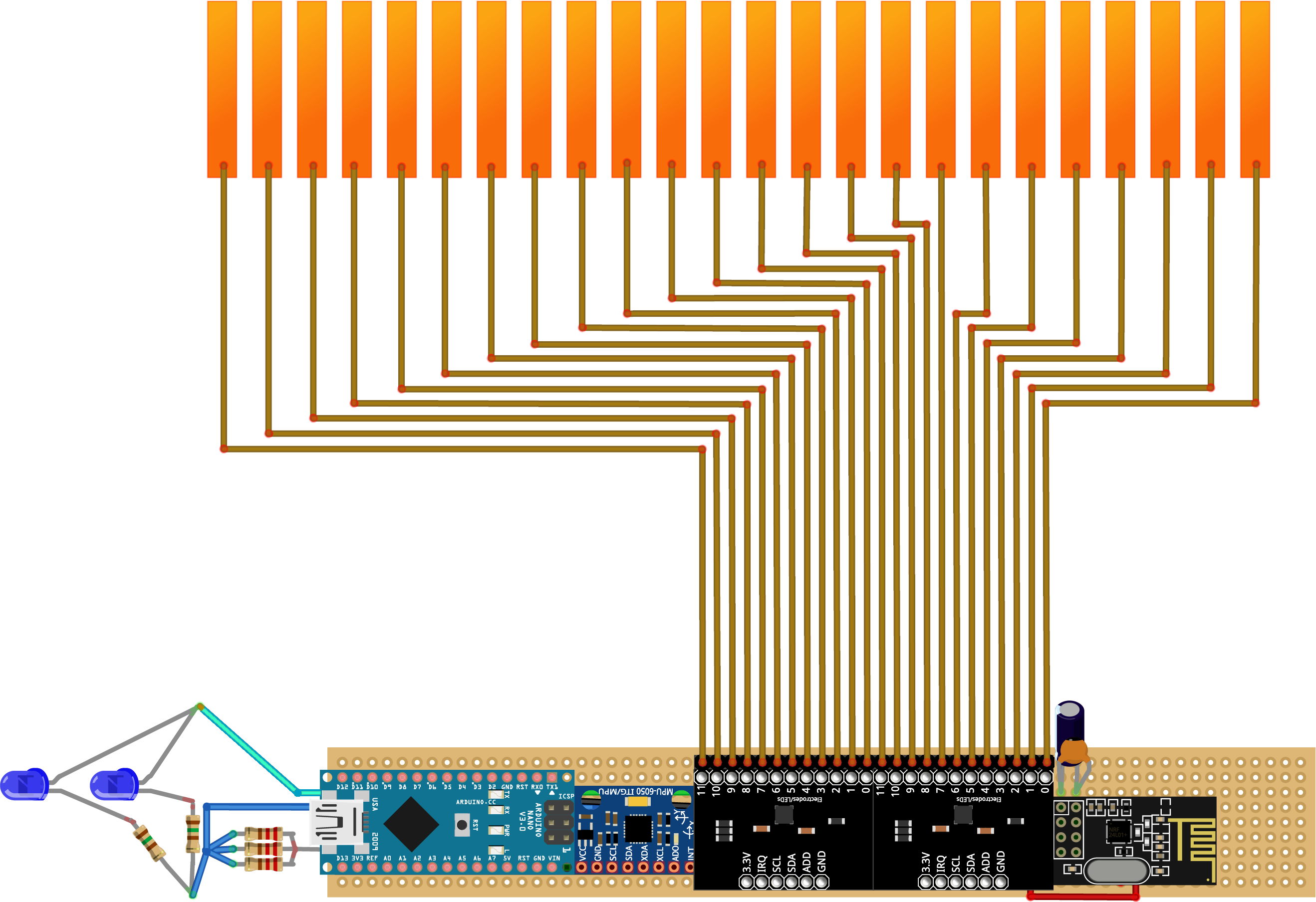
Like the receiver the controller also gets an interface – a touch interface that we will make from copper tape:
It will be connected to the controller board like this:
As we directly want to attach the touch interface to the controller's enclosure, you should already have the (non-conductive) material at hand that you want to make the enclosure from. I used empty boxes that cling film and plastic bags came in:
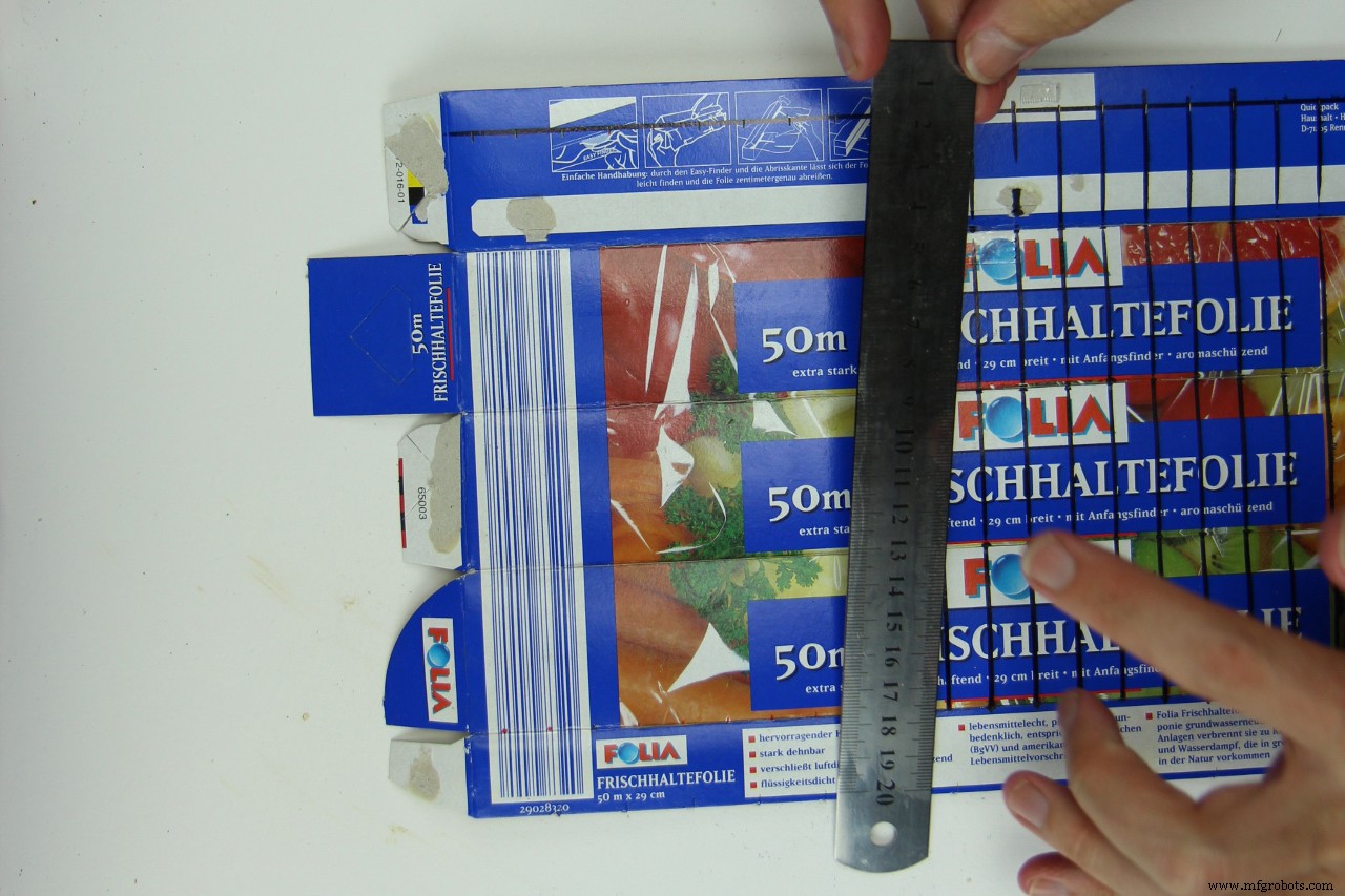
Start making the controller interface by marking where you want to attach the touch electrodes. Please note that they must not touch or overlap each other:
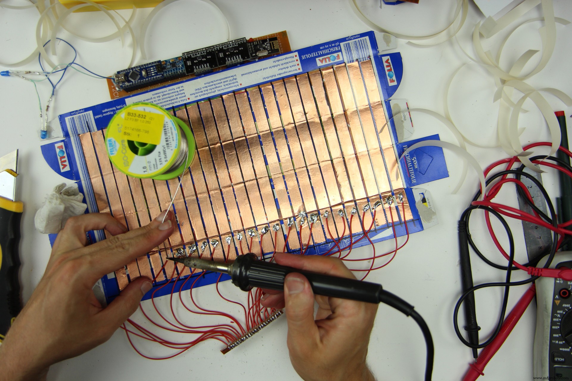
Next, cut the 24 copper electrodes to size...
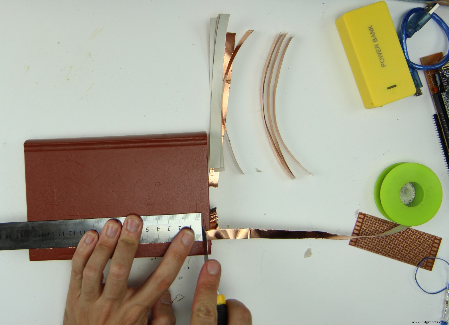
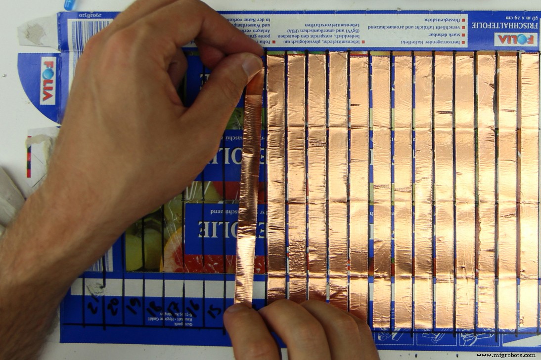
...and attach them to the enclosure:
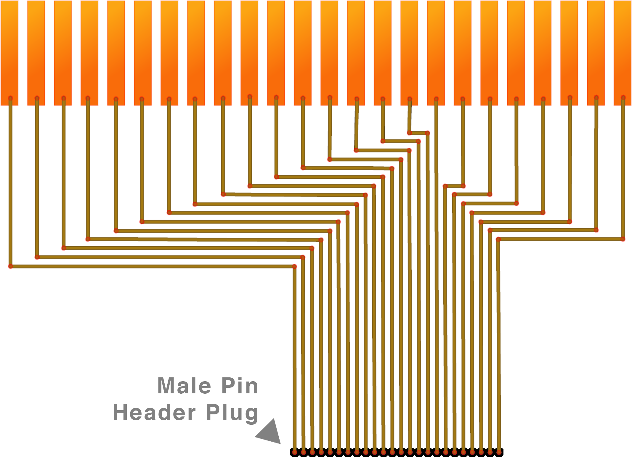
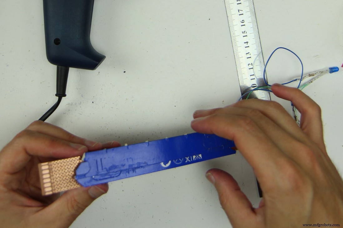
Now we can make the plug. For that cut a 2 * 24 hole wide perfboard and a 24 pin male header to size and solder 24 cables to it. The cables in the middle should be at least 10 cm long. To the outside add the width of your electrodes plus the spacing in between for each cable. If for example you use 1 cm wide copper tape and leave 3 mm between the electrodes, your cable length should increase by 1.3 cm like this 10 / 11.3 / 12.6 / 13.9 / 15.2...
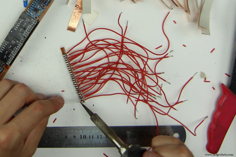
and solder the other ends of the cables to the electrodes like this:
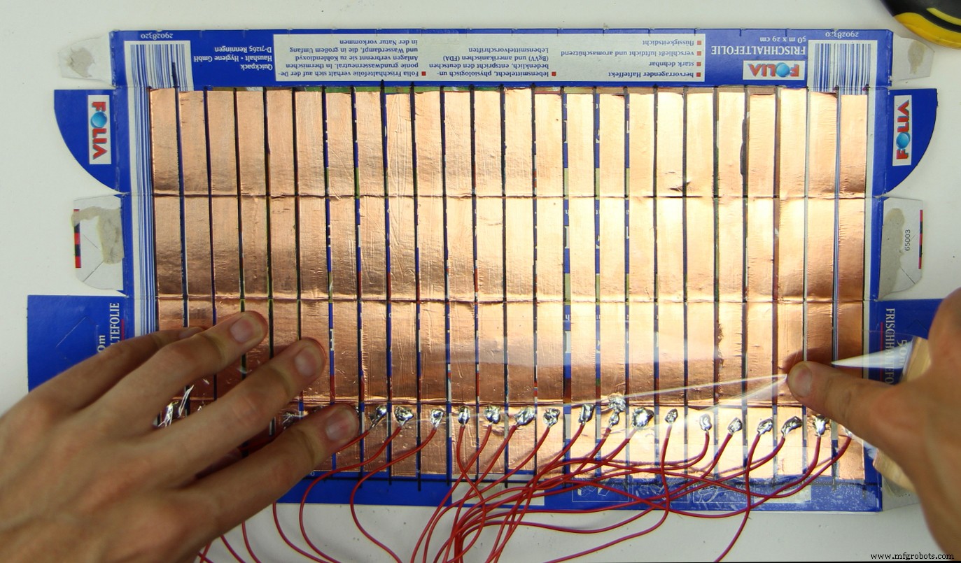
Finish the interface by covering the copper surface with non-conductive adhesive tape:
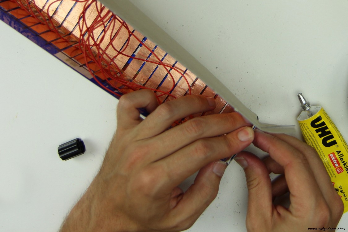
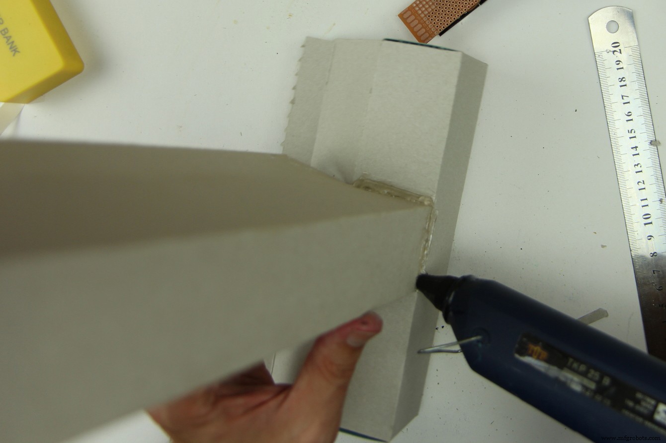
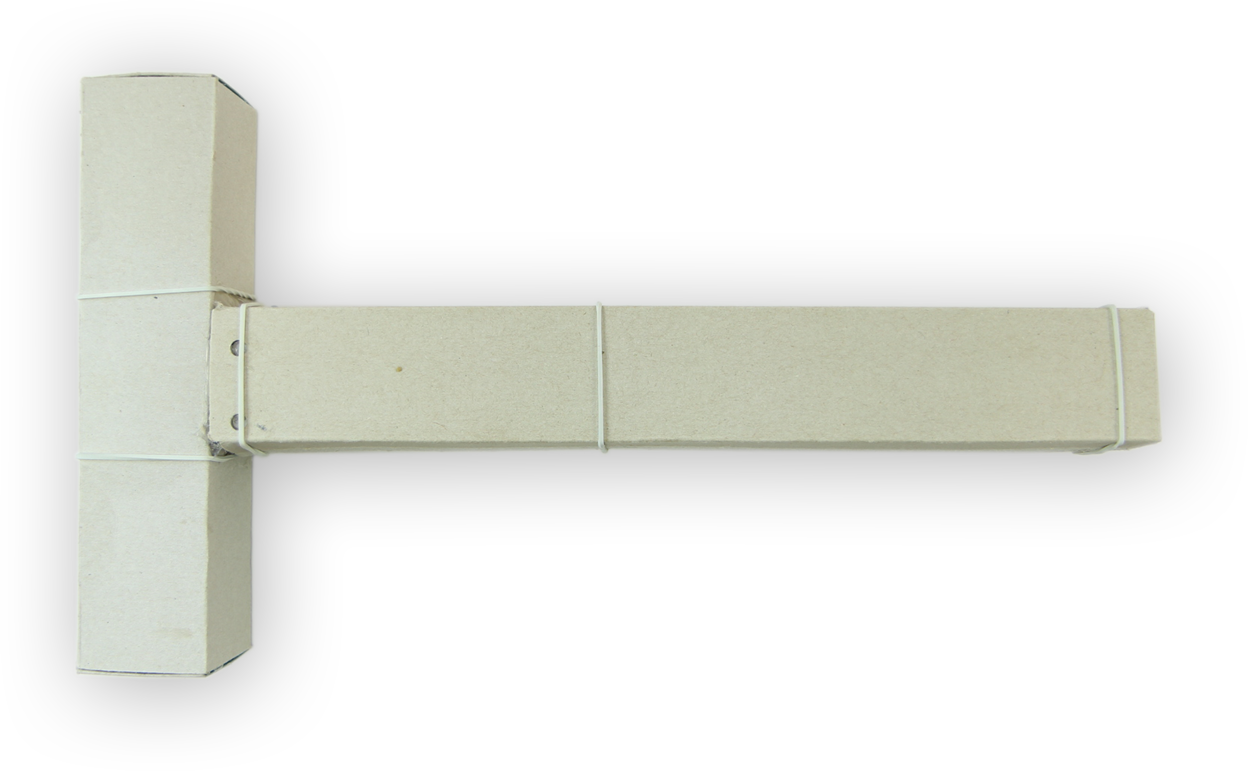
Next fold the interface into a box and glue it:
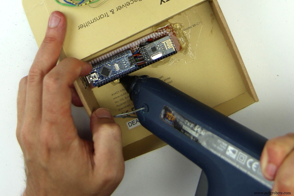
Glue a smaller box to the box we made in the previous step. It later will contain the powerbank:
Cover the back of the controller board with some leftover cardboard orother slightly thicker non-conductive material:
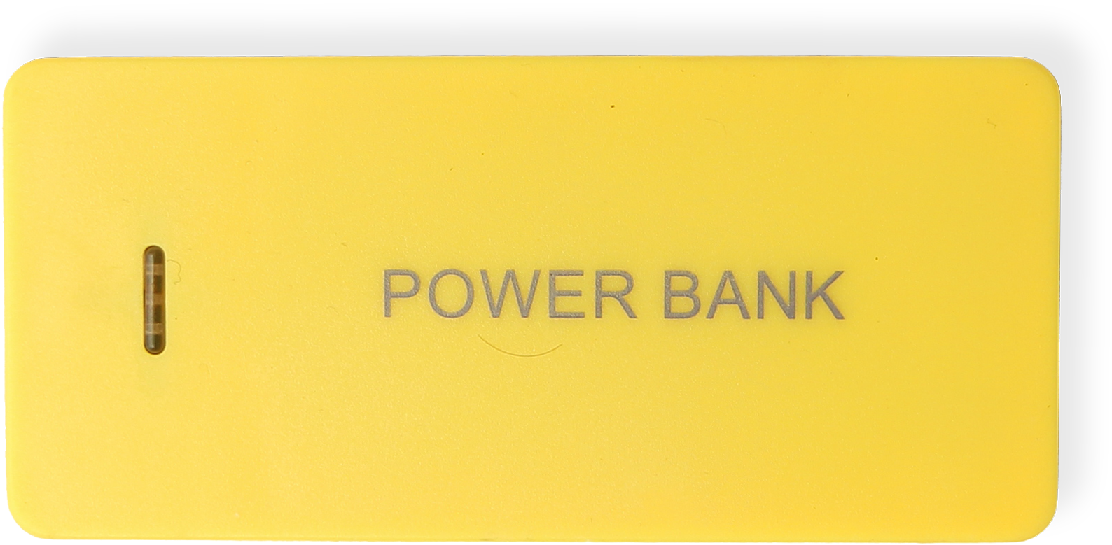
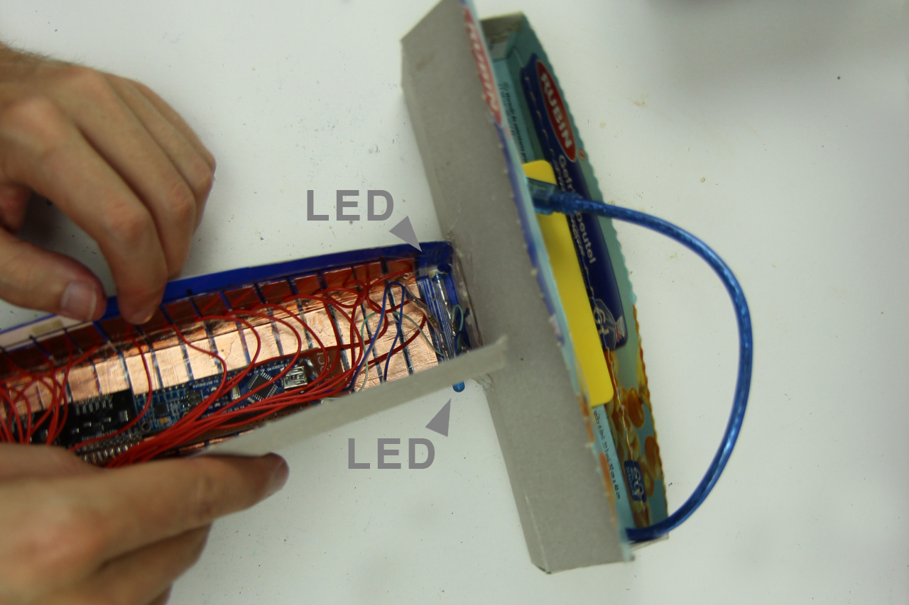
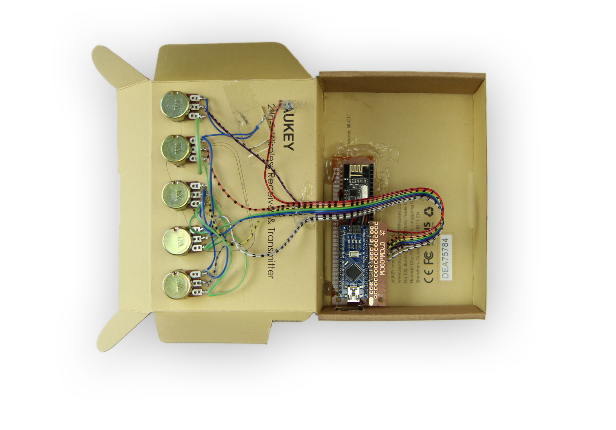
Cut out holes for the LEDs and glue them and the powerbank (yellow object in the picture) in place. Make sure to place the powerbank in a way that you can still plug in and remove the USB-cable because that is how you turn your controller on and off. Also connect the touch-interface to the controller board and put it in the box. Most likely it will not move much, so you do not need to glue it in.
Make a cut out for the USB-A to USB-C cable at the junction of the two boxes, pull it through and connect it to the Arduino Nano:
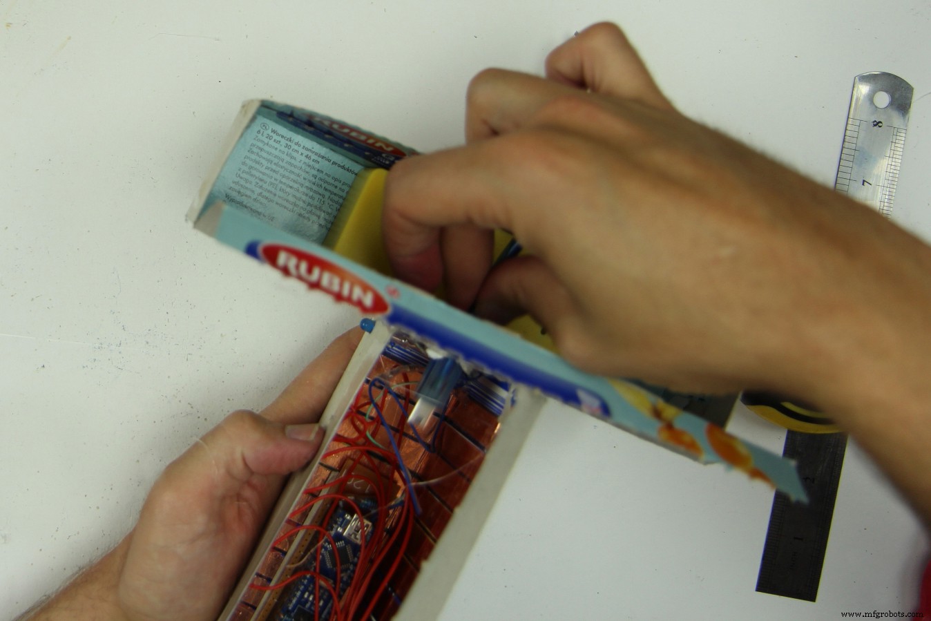
Now the Controller is done!
You can close it with some rubber bands. If you later have problems with the sensors recognizing touch when there is none, try to put some non-conductive material like clingfilm or the like between the touch sensitive enclosure and the board and meandering cables. Also make sure to connect the powerbank when the touch sensitive part of the enclosure does not touch your hands or anything else. See Part 7 for more info.
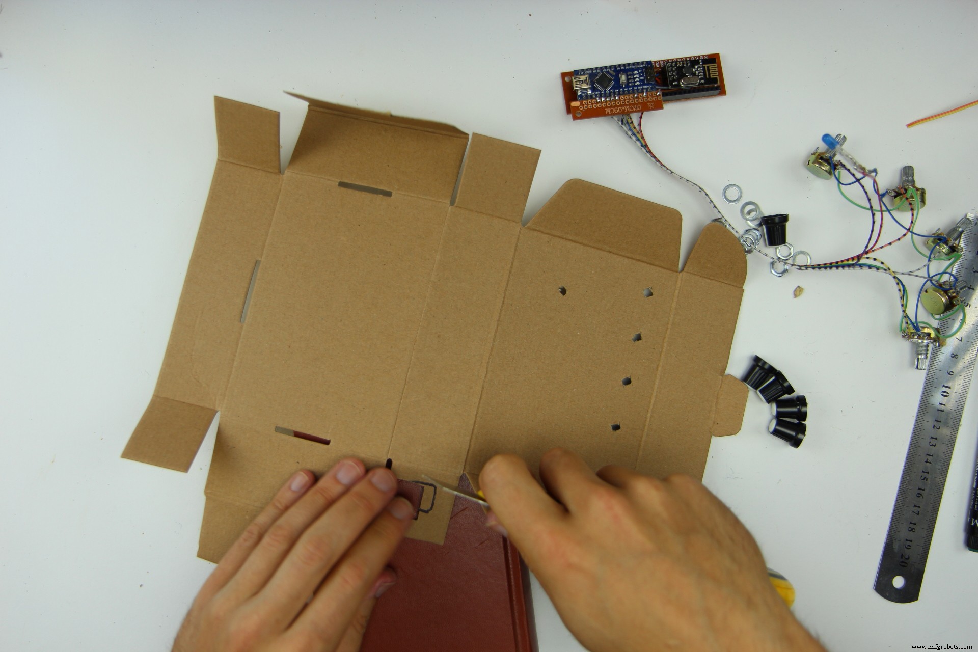
Part 6 – Making the Receiver Enclosure
In part six we will make an enclosure for the receiver as well. You will need another cardboard box (I chose one that contained a bluetooth transceiver before – fitting huh?) and some knobs for the potentiometers
First cut out some circular holes for the potentiometers the LED. Also mak a cut out where you want to connect the USB-Cable to the Arduino Nano
Glue the Receiver board in. Make shure that the USB-C Jack of the Arduino Nano is aligned with the hole that you cut out for the cable connection in the step before.
Next glue in the LED and screw in all the potentiometers. The order how to put them in is the same as in the circuit diagram above:
Now you only need to attach the knobs....
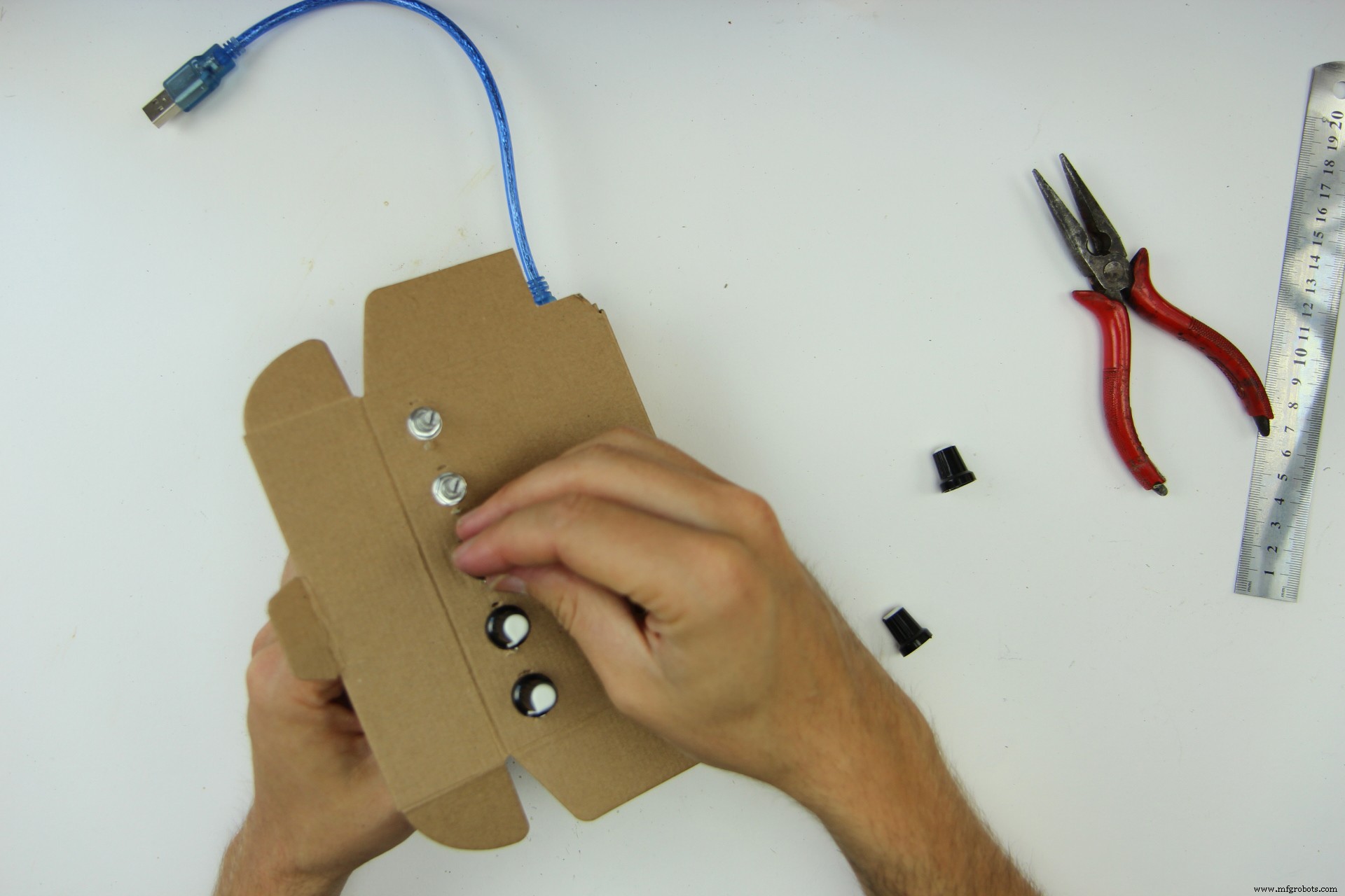
...and the receiver is finished!

Part 7 – Connecting the Receiver to Pure Data
Now that all the hardware is finished, it's time to play some music with it! For that you need software that you can connect the hardware to. For Kravox that software is Pure Data Vanilla that you can download here for free
After installing Pure Data to your computer, start it and open the Kravox.pd file from the attachments. Please note that it needs to be saved on your computer in the same place as the drumsamples folder it comes with - otherwise Pure Data cannot find the samples
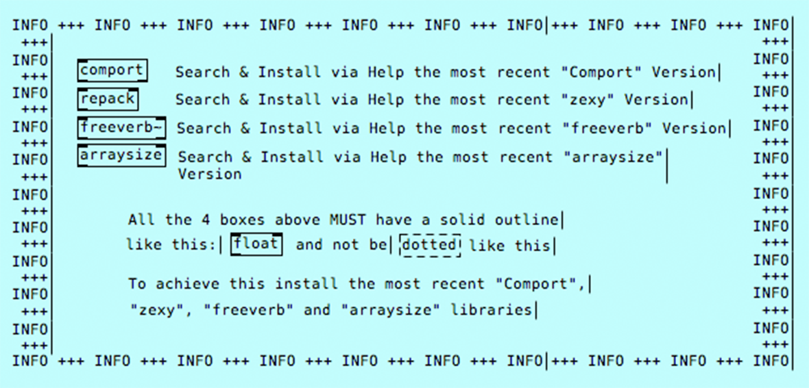
As soon as the Kravox.pd software interface has opened, look for a blue-info box and install the four so-called externals that are listed in the box. Installing them is straightforward:Just click on "help" in the Pure Data Menu, choose "Find additional objects on the internet" (might be phrased slightly different), search for "comport", "zexy", "freeverb" and "arraysize" one by one and install the most recent version. Now the four objects labeled, comport, repack, freeverb and arraysize should have a solid outline like in the picture below. You might need to restart Pure Data for that though
After installing the necessary externals you can connect the Receiver Box via USB. If you altered the code in Part 4 to use the Receiver with the Arduino Serial Monitor you need to undo this change first and upload the original code to the receiver's Arduino Nano before connecting and close the Arduino Serial Monitor, so the receiver is not busy trying to talk to it.
Now have a look at Pure Data's log / info window. If you see a rapidly updating data stream that's great because it means that pure data has already found the receiver, but most likely it will instead show you a red message like the one below that refreshes every other moment:
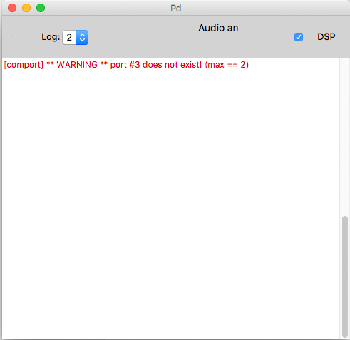
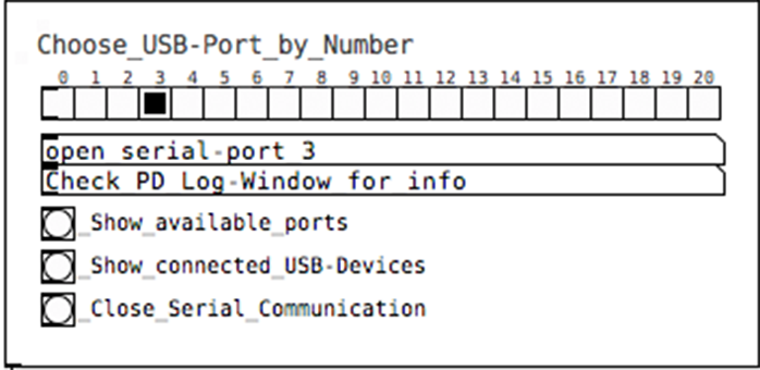
The red message might be a little different, but the result is the same:Pure Data did not yet succeed to connect to your receiver. That is because the program needs to be told, which USB port to listen to. USB-ports are sometimes a bit of a funny thing though:On a 2014 macbook Pro, Pure Data recognizes both USB ports as Serial Port 3, no matter to which you connect the receiver. In Milan I used Kravox with a Lenovo Yoga Pad with only one working USB-Port, that needed to be contacted as Serial Port 6, and recently installed it to another Windows Notebook with two USB-Ports, that wished to be addressed as Serial Ports 8 and 9... So my advice is just to try which number works with your USB-Port. For that I created a simple dialog as part of the Kravox.pd interface, where you can just click through the numbers until one works. You can also try the "Show available ports" and "Show connected USB-devices" buttons – Sometimes, but not very often that also provides useful information. However it takes a while until you get a response in the info window.
You will notice that you have found the right port number and that a connection has been established when the info window shows a data stream like this that updates rapidly:
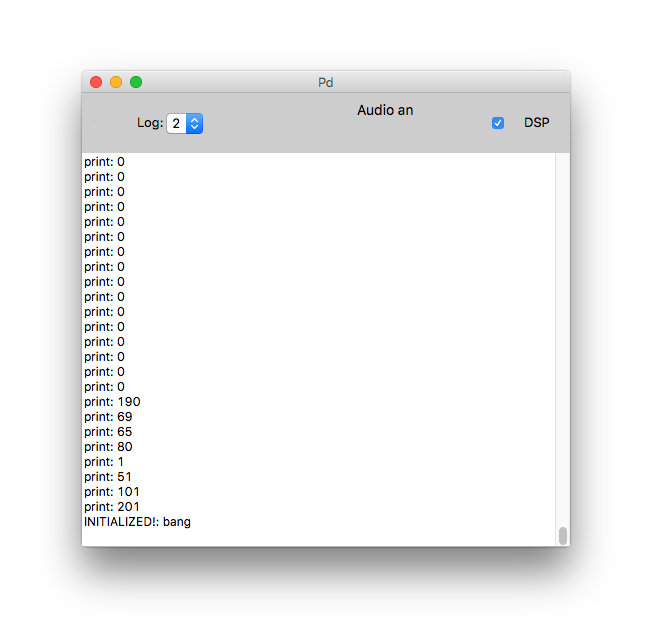
Very good so far! Click save, so Pure Data will attempt to connect to this port the next time it opens automatically.
However we still need to turn the controller on. If you uncommented the last section of the Kravox Controller code in step 2.7 to connect the controller to the Serial Monitor you should upload the original Version again now.
Connect the controller board to the powerbank. When you do this, the touch-interface-enclosure around the the board should be closed and the touch sensitive part of the enclosure should not touch your hands or anything else, as the touch sensors sense their environment when powered up and assume it to be the untouched state
Congratulations – You are done!
Have much fun playing Kravox!
代码
Kravox Code for Arduino and Pure Data
Under this link you can download a Zip-File that contains the Arduino Code for the Kravox controller and the Kravox receiver, the Kravox.pd-file for Pure Data and the necessary drumsamples for the instrument. Please refer to the tutorial for instructions how to use the files.https://github.com/timkrahmer/Kravox示意图

制造工艺