基于蓝牙的家庭自动化
组件和用品
 |
| × | 1 | |||
| × | 1 | ||||
| × | 1 | ||||
| × | 1 |
必要的工具和机器
 |
|
应用和在线服务
 |
|
关于这个项目
电路设计:
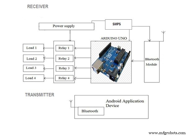
基于Arduino和蓝牙的家庭自动化电路设计非常简单,下面进行说明。蓝牙模块有 4 个引脚:VCC、TX、RX 和 GND。 VCC 和 GND 连接到 Arduino UNO 的 5V 和地。蓝牙模块在 3.3V 电压下工作,它有一个板载 5V 至 3.3V 稳压器。蓝牙模块的 TX 和 RX 引脚必须连接到 Arduino 的 RX 和 TX 引脚。当将蓝牙的 RX 连接到 Arduino(或任何微控制器)的 TX 时,我们需要小心,因为该引脚只能承受 3.3V。但是来自 TX 或 Arduino 的电压将为 5V。因此,使用由10K和20K电阻组成的分压器网络将电压降低到大约3.3V。
工作:
打开电源后,蓝牙模块上的连接 LED 开始闪烁。我们需要在我们的智能手机中启动“蓝牙控制器”应用程序并连接到蓝牙模块。如果配对成功,LED就稳定了。现在,在app中,我们需要为不同的负载设置不同的按键,以及按键按下时必须传输的对应值。下图显示了一组控制4个负载的按键和一个关闭所有负载的附加按键。
该应用程序可以从以下链接下载:
https://drive.google.com/open?id=1nG3IVv4Sfq7oxc6i7c2kwBkIuNLsXeZx
代码
- 代码
代码Arduino
#includeSoftwareSerial BT(0, 1); // arduino 的 TX、RX 引脚分别为String command;void setup(){ BT.begin(9600); Serial.begin(9600); pinMode(2,输出); pinMode(3,输出); pinMode(4,输出); pinMode(5,OUTPUT);}void loop() { while (BT.available()){ //检查是否有可用字节读取 delay(10); //添加延迟以使事情稳定 char c =BT.read(); //进行串行读命令 +=c; //构建字符串。 } if (command.length()> 0) { Serial.println(command); if(command =="light on") //这个命令将作为输入来打开 light1 { digitalWrite(2, HIGH); } else if(command =="light off") //这个命令将作为输入来关闭light1 类似地其他命令工作{ digitalWrite(2, LOW); } else if (command =="lamp on") { digitalWrite (3, HIGH); } else if ( command =="lamp off") { digitalWrite (3, LOW); } else if (command =="fan on") { digitalWrite (4, HIGH); } else if (command =="fan off") { digitalWrite (4, LOW); } else if (command =="open") { digitalWrite (4, HIGH); } else if (command =="lock") { digitalWrite (4, LOW); } else if (command =="all on") //使用这个命令你可以打开所有设备 { digitalWrite (2, HIGH);数字写入(3,高);数字写入(4,高); } else if (command =="off")//使用这个命令可以关闭所有设备 { digitalWrite (2, LOW);数字写入(3,低);数字写入(4,低); }command="";}} //重置变量
示意图

制造工艺


