

钢材焊接中的热影响区和焊缝金属性能
钢材焊接中的热影响区和焊缝金属性能
在焊接碳 (C) 钢和低合金钢时,有许多因素控制着焊缝金属和热影响区 (HAZ) 的性能。焊接金属和热影响区通常被称为钢焊接件。焊接工艺、焊接材料和焊接参数也会影响这些特性。钢焊件的性能还受到其经常承受的腐蚀性气氛和循环载荷的影响。
热影响区
在选择钢材时,热影响区的特性比焊缝金属更重要。这是因为 HAZ 的冶金和机械性能与所选钢材直接相关。然而,这些特性可以通过焊接参数和焊后热处理 (PWHT) 进行调整。此外,与 HAZ 特性相关的冶金和/或可焊性问题比与焊接金属相关的问题更难解决。通常在焊接金属中出现的焊接问题可以通过更换焊条和/或其他焊接材料来解决。相比之下,HAZ 的困难通常只能通过更换基础钢(这通常是一种非常昂贵的措施)或通过改变热输入来解决。开发并利用不同的经验碳当量(CE)来评估基体钢的可焊性和氢(H2)致开裂(HIC)趋势。
国际焊接协会 (IIW) 也使用的最常用的 CE 方程是 CE =% C + % Mn/6 + (% Cu + % Ni)/15 + (% Cr + % Mo + %五)/5。在日本,Ito-Bessyo 成分表征参数 Pcm 的使用更为广泛。与 IIW 方程相比,Pcm 被认为可以更真实地评估低碳钢的可焊性。这个方程是 Pcm =% C + % Si/30 + (% Mn + %Cu +% Cr)/20 + % Ni/60 + % Mo/15 + %V/10 + 5 B。日本开发的另一个方程是对于 C 等效数 (CEN),它包含 CE 和 Pcm 的 IIW 方程。对于 C 含量低于 0.17% 的钢,CEN 与 Pcm 相似,并且在较高 C 含量时遵循 IIW 方程。 CEN 的公式为 CEN =% C + A(C) [%Si/24 + % Mn/6 + % Cu/15 + % Ni/20 + (%Cr + % Mo + % Nb + % V)/ 5 + 5B]。在这个等式中,A(C) 等于 0.75 + 0.25 tan h [20 (% C – 0.12)]。
尽管这些 CE 方程最初是为了表征钢中 H2 的开裂倾向而开发的,但它们也被用于基于化学成分评估钢的淬透性。粗晶区和晶粒细化区的CE、Pcm与马氏体体积均存在相关性。随着Pcm值的增加,两个区域的马氏体体积和硬度都增加。
使用 HAZ 焊接热循环的特定峰值温度和 Fe-C 平衡相图来定义和表征铁素体钢 HAZ 中的各个区域。这些区域是粗粒区、细粒区、临界区、亚临界区和部分液体区。然而,在快速加热和冷却的 HAZ 中的冶金行为是一个非平衡过程。因此,连续冷却转变 (CCT) 图更适合用于预测 HAZ 中的微观结构。冷却速率与钢厚度、接头几何形状和焊接热输入密切相关。通常在焊接应用中最关键的冷却速度是介于 800 摄氏度和 500 摄氏度之间的冷却速度。随着焊接热输入的增加或钢材厚度的减小,这些温度之间的冷却速度会降低。
C和低合金钢中主要合金元素对HAZ显微组织和韧性的影响表明,C对焊接钢的整体硬度具有非常重要的作用。从它在 CE 和 Pcm 方程中的作用可以清楚地看出这一点。 C含量的增加有利于贝氏体和马氏体等低温相变产物的形成,并导致HAZ抗裂性显着降低。
锰 (Mn) 除了固溶硬化外,还降低奥氏体向铁素体的转变温度,同时通过晶粒细化提供强化效果。但要限制Mn的含量,以尽量减少凝固偏析和显微组织条带。
铬(Cr)是一种固溶强化和碳化物形成元素。它增加了钢的淬透性,提高了抗氧化性和耐腐蚀性。在Cr碳化物的析出通过钉扎效应抑制铁素体侧板形成的情况下,添加Cr是有利的。
镍 (Ni) 被认为与 Mn 相似,通过降低奥氏体转变温度对钢的转变产生有益的影响。 Ni的添加还提高了韧性,并提供了固溶强化效果。
在低合金钢中添加少量钒 (V) 和铌 (Nb) 以获得所需的机械性能。通过形成V(C,N)和Nb(C,N),V和Nb在轧制和正火过程中延缓了奥氏体的再结晶和晶粒长大。在熔焊过程中,特别是在高热输入的情况下,V(C,N) 和 Nb(C,N) 在峰值温度超过 1100 摄氏度的热影响区中溶解,并在较慢的冷却过程中重新沉淀。 V(C,N)和Nb(C,N)的再析出削弱了热影响区的韧性。
钛 (Ti) 以稳定的氮化钛形式存在,可防止靠近焊缝熔合边界区域的原始奥氏体晶粒粗化。
焊接金属
填充材料的使用在许多熔焊工艺中非常普遍。在选择合适的填充金属/焊条时,主要考虑的因素是焊缝金属是否可以生产出无缺陷的焊缝金属,以及焊缝金属是否与母材相容并能提供令人满意的性能。这些特性取决于 (i) 电极的化学成分,(ii) 基础钢的稀释度,(iii) 助熔剂或保护气体,以及 (iv) 熔池凝固和随后的冷却和转变。
选择合适的填充材料不是基于化学成分与基础钢的匹配。相反,它基于匹配焊缝金属和基础钢的特性。使用化学成分与基础钢相同的填充材料可能无法达到预期的效果,因为焊缝金属的微观结构与基础钢的微观结构完全不同。对于许多 C 钢和低合金钢,在熔焊中涉及的凝固和快速冷却速度导致焊缝金属在具有相同化学成分时比基础钢具有更高的强度和更低的韧性。因此,填充材料的碳含量通常低于基础钢。提高焊缝金属的强度不是通过增加C含量来提高的,而是通过添加合金元素来提供固溶或沉淀强化和微观组织改性。
C钢和低合金钢的焊缝金属微观结构包含多种成分,从块状铁素体到针状铁素体,再到贝氏体,再到马氏体。合金元素和冷却对焊缝金属显微组织的影响如图1所示,合金元素对焊缝金属硬度和缺口韧性的影响如图2所示。
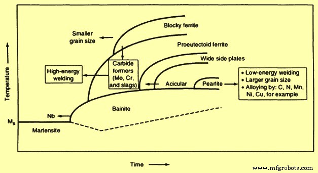
图1合金元素和冷却对焊缝金属微观结构的影响
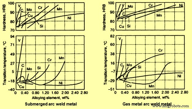
图2合金元素对焊缝金属硬度和缺口韧性的影响
基础钢的熔化和随后与填充材料的混合导致焊缝的最终化学成分介于基础钢和填充材料的化学成分之间。当填充材料与基础钢具有相同的化学成分时,最终的焊缝金属化学成分理论上保持不变。根据熔化的基体钢的量和添加的填充材料的量,焊接熔敷的最终化学成分可以使用稀释方程估算,即稀释百分比 =(熔化的母钢重量/使用钢的总重量) ) x 100。接头配置和边缘准备等因素会影响稀释。增加熔深的焊接工艺和参数也会增加稀释度。
在单道焊缝中,焊缝金属中某些元素的含量可以使用公式“焊缝金属中的特定元素 =(母材中的元素 x 稀释度)+(填充材料中的元素)x(1 – 稀释)”。在某些情况下,更大的稀释是有利的,因为在融合边界上的机械和其他特性的剧烈变化较小。然而,在涉及焊接熔覆或焊接堆焊的应用中,更希望最小化稀释。这是因为填充材料包含更昂贵的合金元素,这些元素被定制以赋予特定的焊接金属性能。当担心基础钢会引入不希望的杂质和/或合金元素时,建议使用降低稀释度的焊接技术。这还包括考虑磷(P)和硫(S)以及较高的C和硅(Si)含量,这会对焊缝金属的性能产生不利影响。
单道焊和多道焊的比较
在机械性能,特别是韧性方面,多道焊缝金属通常优于单道焊缝金属,原因如下: (i) 每个后续焊道的再热热循环使先前焊缝金属中的微观结构部分正常化和细化, (ii) 后续焊道回火前道焊缝金属并减少前道道的应力,(iii) 减少每道次的总能量输入,这有助于限制晶粒生长量,以及 (iv) 前道焊道提供一定的预热会减慢后续道次的冷却速度。
可以看出,焊缝金属的延展性(横截面积)随着总晶粒细化面积的增加而增加。此外,当在埋弧焊(SAW)中使用活性焊剂时,要在接头中施加的焊接道次的数量是有限的。这是因为在多道焊接过程中,合金元素(如 Si 和 Mn)容易堆积,从而降低最终焊道的断裂韧性值。
焊接性和钢材类型
与传统的 C 钢相比,高强度低合金 (HSLA) 钢旨在具有增强的机械性能和可焊性。这些改进是通过添加少量合金元素,如 Nb、V、Ti、N2(氮)和 C 来获得的,这些元素可以强化铁素体、提高淬透性并控制晶粒尺寸。这些钢中的大多数以轧制、正火状态供应,有些也以经过沉淀处理的状态供应。较细的晶粒尺寸和较大量的珠光体说明这些钢具有较高的强度和韧性。此外,这些钢的 C 含量较低(最大为 0.22 %),因此具有良好的可焊性。
通常,HSLA 钢的可焊性与低碳钢相似。尽管 HSLA 钢具有良好的可焊性,但在焊接过程中考虑预热和控制 H2 对于确保成功焊接仍然很重要。粗晶 HAZ 的脆化是 HSLA 钢焊接过程中关注的问题之一。这种脆化是由于缓慢的冷却速度导致形成不希望的微观结构,例如粗大的铁素体侧板(Widmanstätten 铁素体和上贝氏体)和晶界铁素体,尤其是在高能量输入水平下。
对于含有 Nb 和 V 的 HSLA 钢,焊缝金属和 HAZ 在高热输入下表现出低缺口韧性,例如电渣焊 (ESW) 和 SAW 焊接工艺中使用的那些。这是因为高热输入增加了粗粒 HAZ 的范围。 HAZ 中相关的低冷却速率降低了晶粒细化的可能性,增加了 Nb 和 V 碳化物析出的可能性,导致粗晶粒 HAZ 脆化。高热输入和由此产生的较高稀释度也给焊缝金属带来了Nb和V碳化物的沉淀硬化问题。
已发现使用添加少量 Ti(最多 0.04%)和 N2 的钢可以有效地减少粗晶 HAZ 中的晶粒生长。这是因为氮化钛在粗晶区域(超过 1100 摄氏度)的峰值温度下具有更高的稳定性,此时 Nb 和 V 碳化物重新溶解。
低碳钢包括两种类型的钢,即 (i) 碳含量低于 0.15% 的低碳钢和 (ii) 碳含量在 0.15% 和 0.30% 之间的低碳钢。对于这些退火状态的低碳钢,主要的显微组织是相对较软的铁素体,散布着小的碳化物颗粒,而在热轧或正火状态下的低碳钢有珠光体岛。在熔焊过程中,热影响区在加热时从铁素体转变为奥氏体,在冷却时从奥氏体转变为铁素体。在此 C 级,HAZ 中涉及的硬化约为 10 HRC 或更少。
但是,当焊件进行冷成型操作时,通常建议将 C 含量限制在 0.06%。含碳量较高的钢的热影响区一般不具备良好的延展性来适应冷成形所涉及的应变。
当低 C 钢作为沸腾钢供应时,其中心核心区域往往含有浓度较高的化合物,如一氧化碳 (CO) 和二氧化碳 (CO2),以及 S 和 P 等元素,这是在生产过程中偏析的结果。翻边动作。此外,溶解氧 (O2) 和 C 反应产生的气体也被困在中心核心区域。在焊接操作期间,由于稀释,一些基础钢熔化并与填充材料混合。液态熔池的高温提供了条件,允许不完全的 O2-C 反应恢复并释放捕获的 CO 和 CO2。当焊接熔池凝固速度非常快,气体逸出时,它们的截留会导致焊缝金属中出现气孔。因此,充分的焊池脱氧是避免在焊接沸腾钢时出现气孔问题的实用方法。
当低碳钢作为镇静钢供应时,熔焊过程中焊缝金属气孔不再是问题。相反,镇静钢的熔池表面有时会形成粘性的耐火熔渣,这使得液态金属流动缓慢,熔池操作困难。当脱氧剂(例如 Al(铝)、Ti 和 Zr(锆))用于钢的杀伤实践中时,熔渣会变得粘稠,形成具有相对较高熔化温度的氧化物。由于该过程涉及低温,因此使用氧乙炔焊接时,熔渣问题更加严重。通常的解决方法是选择含有足量Mn和Si的填料,以降低熔点,改善渣的流动性。
低碳钢也被认为是可焊接的,当 C 含量低于 0.2% 和 Mn 含量低于 1.0% 时,冷裂纹通常不会成为问题。焊接厚度为 25 毫米及以下的钢时,通常不需要预热、道间温度控制、PWHT 或特殊焊接技术。为了提供所需的强度,较厚的钢中的 C 含量通常较高。此外,较厚钢的熔焊过程中相关的热影响区冷却速率较高。因此,当焊接厚度大于 25 mm 的钢时,或当 C 和 Mn 含量分别高于 0.3 % 和 1.4 % 时,需要采取适当的预防措施并使用低 H2 焊条或焊剂来防止 H2 开裂。
在选择具有最佳可焊性和韧性的 C-Mn 和微合金化 C-Mn 钢时,提供了一个有用的建议,如 Dolby 所建立的。对于这些含碳量超过 0.1% 的钢,应使用同时具有低 C 含量和低 CE,但具有高韧性的钢基。需要选择经过铝处理的钢,以限制 HAZ 中粗晶粒区域的宽度并最大限度地减少游离 N2 水平(氮化铝沉淀物相对稳定)。选用的钢材要干净。铝处理或真空脱气的钢具有较低的 S 水平。用于硫化物形状控制的钙(Ca)处理改善了整个厚度方向的力学性能,并减少了与液化开裂问题相关的层状撕裂。
当对具有相同 C-Mn 成分的基础钢使用高能量输入焊接工艺时,添加 Nb 和 V 会降低 HAZ 韧性,因为在冷却和再加热过程中会析出 Nb 和 V 碳化物或碳氮化物。含碳量低于 0.1% 的微合金钢通常具有更高的韧性,并且热影响区的 H2 开裂倾向降低。由于上述 C-Mn 钢的原因,需要选择具有高韧性值的干净的铝处理钢。对于高能量输入的焊接工艺,同样的预防措施也适用于上述。
需要选择具有低C水平的低合金钢。当钢的淬透性足以在所用焊接条件下形成低碳马氏体时,可以获得高抗劈裂性。对有大量二次析出的硬化合金元素如 Nb 和 V 的钢的 PWHT 需要小心。还应注意含有大量残留元素如 P、Sb(锑)的钢的 PWHT )、As(砷)和 Sn(锡)。
由于上述 C-Mn 钢的原因,应选择具有高韧性值的干净的 Al 处理钢。此外,这里也适用于高能量输入焊接过程的相同预防措施。
热机械控制工艺 (TMCP) 钢显示出显着提高的强度和韧性特性以及可焊性。该技术使用加速冷却,可以在较低的 C 水平下达到与传统受控轧制钢在较低 C 水平(小于 0.06 %)下达到的强度水平相同的强度水平。 TMCP 钢不是通过增加 C 含量来强化,而是从过程加速冷却阶段出现的非常细的铁素体和第二相微观结构(细分散的珠光体或贝氏体)发展其强度和韧性。由于 C 含量和 CE 的降低,这种钢显着提高了抗 H2 致冷裂纹 (HICC) 的能力。因此,与焊接过程中的预热、道间温度控制和 PWHT 相关的担忧并不重要。然而,热影响区的软化,尤其是在高热输入下,是一个令人担忧的问题,因为在高热输入水平下的热影响区缓慢冷却过程中,TMCP 钢的有利微观结构会发生逆转。
与高合金钢相比,Cr-Mo(钼)钢是一种相对便宜的材料,由于其抗氧化性、抗高温蠕变性和抗硫化物腐蚀性能,被用于电力和石油化工行业。 Cr含量使钢具有抗氧化腐蚀性,而Mo含量提高了高温强度。精细分布的稳定碳化物的存在提高了抗蠕变性。由于合金元素含量和大约 0.15% 的 C 水平,这种钢是可空气硬化的。这种钢通常以正火和回火或淬火和回火 (Q&T) 状态供应。 Cr-Mo钢的可焊性与Q&T和可硬化低合金钢非常相似。 HAZ 的主要问题是硬化粗晶粒区域的开裂,以及在 Ac1 和 Ac3 温度之间的 HAZ 软化。 PWHT 过程中的再热开裂和长期暴露在高温下也会造成严重的困难。该钢需选择合适的预热温度和道间温度,并采用低H2焊接工艺。
虽然对于 Cr 含量较低且规格较薄的 Cr-Mo 钢不需要 PWHT,但作为焊接技术的一部分,通常在焊接后立即进行 PWHT。 Cr-Mo 焊件的 PWHT 有时也被称为消除应力热处理。这种热处理旨在通过蠕变松弛过程消除残余应力,并回火焊接硬化的微观结构,以提高热影响区和焊缝金属的断裂韧性。 PWHT 的额外有益效果是允许 H2 在焊接区域中的更高耗散并进一步降低 HICC 的可能性。尽管在 Cr-Mo 钢焊件中经常使用应力消除处理或 PWHT,但这种类型的钢在这种处理过程中容易出现热影响区的应力消除开裂或在焊后再加热过程中出现再热开裂,包括短期暴露在高温大气中。应力消除/再热开裂的发生温度范围在 500 摄氏度到 700 摄氏度之间。虽然尚不清楚,但据信开裂机制与沉淀导致晶粒内部的强化有关。
当没有析出物的相对软的晶界不能适应蠕变松弛过程中的塑性变形时,再加热过程中就会发生开裂。已经开发了一个称为“Psr”的参数,用于关联 Cr-Mo 钢在含有最大 1.5% Cr、最大 1.0% Cu、最大 2.0% Mo 和最大 0.15% V、Nb 时对再热开裂的敏感性,和钛。该关系由等式“Psr =%Cr + %Cu + 2x %Mo + 10x %V + 7x %Nb + 5x %Ti – 2”给出。
当 Psr 小于零时,认为材料对再热开裂敏感。然而,当Cr含量超过2%时,裂纹的趋势就消除了。另一个考虑杂质元素并导致晶界脆化并增加再热开裂趋势的参数是“金属成分因子”(MCF),由方程式“MCF =%Si + 2x %Cu + 2x %P + 10x %As + 15x %Sn + 20x %Sb'。较高的MCF值也增加了Cr-Mo钢的再热裂纹敏感性。
用于减少再热开裂可能性的常用焊接技术总结为(i)减少焊件设计中的应力上升,(ii)使用最小化残余应力的焊接实践,例如提高预热温度和减少约束, (iii) 在适用和必要时降低焊缝金属强度以适应焊缝金属中的塑性变形,以及 (iv) 减少粗晶粒区域的应力集中。
Q&T 钢通常以热处理状态供应,包括奥氏体化和/或淬火和回火以获得高强度性能。 Q&T 钢的淬透性使得热影响区由低碳马氏体和贝氏体的显微组织组成。这种类型的焊接 HAZ 微观结构具有与基础钢接近的理想机械性能。因此,这种钢通常不需要PWHT或去应力处理,除非在某些特殊情况下。
与其他使用高能量输入以避免在热影响区形成马氏体的可硬化低合金钢不同,Q&T 钢的使用需要焊接条件包括热影响区中的冷却速度,该冷却速度足够快以确保再形成马氏体和贝氏体显微组织。这是必要的,因为 HAZ 的冷却速度太慢而无法使奥氏体化的 HAZ 转变为铁素体以及贝氏体和马氏体的混合物。在奥氏体向先共析铁素体转变过程中,未转变的奥氏体富集C,然后转变为硬而脆的贝氏体和马氏体。这种铁素体、贝氏体和马氏体的混合微观结构导致粗晶粒热影响区的脆化。冷却速度越慢,HAZ 的脆化程度就越大。在焊接难硬化或薄钢时,需要更快的临界冷却速度(更少的热输入)来避免脆性混合组织的转变。
Q&T 钢焊接过程中的另一个问题是严格维护低 H2 焊接技术,以防止焊道下冷裂纹。预热是减少冷裂倾向的最有效方法之一。然而,预热也显着降低了热影响区的冷却速度。因此,应以能够在热影响区达到令人满意的快速冷却速度的方式应用它。
当焊接具有较高强度水平的Q&T钢时,焊缝金属中发生H2裂纹的趋势增加。因此,电极涂层和助焊剂中允许的水分含量以及这些材料的处理变得更加关键。对于屈服强度 (YS) 水平低于 480 N/sq mm 的 Q&T 钢,0.4% 的水分含量是覆盖焊条的允许限值,而对于强度水平高于 690 N/sq mm 的钢,该限值为 0.1%。回火焊道技术的使用也有助于避免热影响区中不希望出现的高硬度和低韧性区域。
多道焊是Q&T钢焊接的一种很好的技术。除了对前道焊缝金属的精炼和回火作用外,与单道焊相比,多道焊的较小热输入有助于实现较快的冷却速度。如果担心焊缝金属中的 H2 开裂,则应使用薄层多道焊,同时在道间温度下浸泡预定时间,然后再沉积下一道道次。虽然这种技术有助于在每个焊道中消散焊缝金属中的 H2,但它会降低生产率。
在 Q&T 钢中,HAZ 中有一个软化区,这是由 HAZ 热循环引起的,其峰值温度在 Ac1 和 Ac3 之间(临界区)。在加热过程中低于 Ac3 的温度下,碳化物没有完全溶解在奥氏体中。因此,奥氏体中的 C 水平应具有较低的浓度。在冷却过程中,不饱和奥氏体在高温下发生转变,导致显微组织强度降低。
焊件中的注意事项
用于结构应用的碳钢和低合金钢通常不用于严重腐蚀性环境。但是,它们通常用于中等腐蚀性条件,例如炼油厂和酸性气体/石油管道。焊缝的存在通常会导致耐腐蚀性降低,原因如下:(i) 基础钢、HAZ 和焊缝金属的成分变化导致有利于电偶腐蚀的情况,(ii) 残余应力的存在导致应力腐蚀开裂 (SCC) 的焊接,以及 (iii) 存在焊接不连续性(如表面缺陷),这是局部腐蚀攻击的有利位置。
在腐蚀性气氛中,防止 HIC 和硫化物应力腐蚀开裂 (SSCC) 很重要。 HIC 已在高强度和低强度钢中观察到,即使在无应力条件下,也主要发生在暴露于含 H2 气氛的低强度钢中。由于其快速冷却和凝固,焊缝金属形成枝晶结构,并具有以细小球状分散的氧化物夹杂物。可以看出,即使在没有特殊化学填充金属的情况下使用焊缝金属,也不会产生 HIC,最大硬度为 280 HV。相比之下,HIC主要出现在基础钢和HAZ中。
SCC 被定义为在硫化物腐蚀条件下钢受到应力时发生的开裂现象。 Steel which is to be used in atmosphere containing H2 sulphide (H2S) can be suitably chosen.一般建议用22 HRC(248 HV)作为用于酸性气体应用的管线钢的硬度限值。
在焊接件的情况下,HAZ 通常变得比基础钢更硬,因此更容易受到 SCC 的影响。除了更易受影响的微观结构之外,对 SCC 产生不利影响的其他因素是焊接残余应力和作为焊接区域应力升高的焊帽的进入角的存在。当焊接接头 Q&T 或正火时,HAZ 消失,先前的 HAZ 发展 SCC 的趋势发生了变化。焊态状态下的 SCC 敏感性高于 Q&T (PWHT) 状态下。
在循环载荷作用下,焊接结构中的疲劳裂纹经常出现在焊趾区域。这是因为焊趾是应力集中区域。趾部是基础钢和焊接金属相遇的点,并且在这两个部分中变化最大。此外,由于焊接操作导致的熔渣侵入也经常出现在焊趾区域。不同的技术已被用于通过减少焊趾和焊缝加强区域的应力集中来提高焊接结构的疲劳强度。这些技术是(i)通过将焊缝加工到基础钢水平去除对接接头两侧的焊缝加强,(ii)通过机械研磨焊缝之间的相交区域来增加焊趾的半径和进入角,以及the base steel, (iii) changing the state of surface weld residual stress by the mechanical cold working of the weld surface and the base steel at the weld toe region, (iv) coating and painting the welds and base steel to prevent corrosion in the region of stress concentration, (v) increasing the toe radius and weld entrant angle by adding a weld bead on both sides of the reinforcements using a filler material with high fluidity, (vi) using welding conditions which result in a greater weld toe radius and entrant angle, and (vii) re-melting the surface in the weld toe regions for flattening and smoothing weld profiles using the gas tungsten arc welding (GTAW) process.
Effect of welding technique on the properties of steel weldment
The American Welding Society (AWS) defines a welding technique as the detailed method and practice which includes all joint welding processes involved in the production of a weldment. In a detailed review of the relationship between techniques and weldment properties, the following are the conclusions.
- For any welding process/steel combination, welding techniques have a predominant role, along with the electrode (if a filler material is used), in determining the quality and mechanical properties of the weldment. However, these two variables (welding techniques and mechanical properties) do not have a direct cause-effect relationship.
- The mechanical properties of steel are attributable only to its soundness, microstructure, and chemical composition, and to whether or not it is base steel, weld metal, vapour-deposited metal, electrodeposited metal or any other type. The response of steel to mechanical forces depends on its present state and not on the manner in which this state has been created.
- Metallurgical research has established relationships between mechanical properties and microstructure, such as the inverse relationship between grain size and strength, the difference in strength between pearlite and martensite, the embrittling effect of grain boundary films, the harmful effect of inclusions, and others. On the other hand, there is no direct relationship between the current setting of a welding machine and the final properties of the weldment. Rather, the true cause and effect relationship is that (i) increased current introduces more heat into the steel, (ii) increased heat affects both the HAZ and the structure of the weld metal in a particular manner, depending on the steel chemistry, phases which are present, and other factors, and (iii) difference in structure results into different mechanical properties.
The factors connected with the specific welding technique, which affect weldment properties are given below.
Temperature of preheat
Preheating is the application of heat to the base steel immediately before welding, brazing, soldering, or cutting. The preheat temperature depends on many factors, such as the composition and mass of the base steel, the ambient temperature, and the welding technique.
Preheating is done for (i) reducing shrinkage stresses in the weld and adjacent base steel which is mainly important with highly restrained joints, (ii) making available a slower rate of cooling through the critical temperature range (around 880 deg C to 720 deg C), which prevents excessive hardening and lowers the ductility of both the weld and the HAZ of the base steel, and (iii) making available a slower rate of cooling down to 200 deg C, allowing more time for any H2 which is present to diffuse away from the weld and adjacent steel in order to avoid under bead cracking.
Gas torches, gas burners, heat treating furnaces, electric resistance heaters, low frequency induction heating, and temporary furnaces are some of the preheating methods which are used. The selection of the method depends on many factors, such as the preheat temperature, the length of preheating time, the size and shape of the parts, and whether it is a ‘one of a kind’ or a continuous production type of operation. For critical applications, the preheat temperature is to be precisely controlled. In these cases, controllable heating systems are used, and thermocouples are attached directly to the part being heated. The thermocouple measures the exact temperature of the part and provides a signal to a controller, which regulates the fuel or electrical power required for heating. By accurately regulating the fuel or power, the temperature of the part being heated can be held to close limits. Many standards need precise heat temperature control.
Temperature of inter pass
The inter pass temperature, which is involved in multi pass welds, is denoted by the minimum and maximum temperatures of the deposited weld metal and adjacent base steel before the next pass is started. Normally, steel which needs preheating to a specified temperature is also to be kept at this temperature between weld passes. With many weldments, the heat input during welding is adequate to maintain the inter pass temperature. On a massive weldment, it is not possible that the heat input of the welding process is enough to maintain the required inter pass temperature. If this is the case, then torch heating between passes is usually needed.
Once an assembly has been preheated and the welding has begun, it is required to finish welding as soon as possible in order to avoid the need for inter-pass heating. Because the purpose of preheating is to reduce the cooling rate, it logically follows that the same slow cooling is to be given for all passes. This can only be done by maintaining an inter pass temperature which is at least equal to the preheat temperature. If this is not done, then each individual bead is subjected to the same high quench rate as the first bead of a non-preheated assembly.
The required minimum temperatures which are needed are based on specific steel, welding process, and steel thickness. When heat buildup becomes excessive, the weldment is to be allowed to cool, but not below the minimum inter pass temperature. The temperature of the welding area need to be maintained within minimum and maximum inter pass temperatures.
Post weld heat treatment
A PWHT is normally considered necessary for welds in thicker section steel, in order to reduce the high as welded residual stress level and improve the toughness and defect tolerance of the joint. Many fabrication standards provide guidelines on the duration and temperature of the PWHT, although some differences between various standards exist. In assessing the time and temperature needed to provide a suitable PWHT, it is necessary to know how such parameters respond to different heat treatment schedules.
In all heat treatments, with the possible exception of fusion, the heating rate and time can be specified. The maximum temperature is related to the composition of the steel, the holding time (at the maximum temperature) is related to the steel thickness, and the cooling rate is related to the particular treatment and to the standard. The rate of heating generally ranges from 150 deg C to 180 deg C per hour. The holding time is typically 2.5 min/mm of maximum thickness in order to provide uniform heating throughout. The cooling rate also ranges from 150 deg C to 180 deg C per hour, down to a specific temperature. In some cases, the cooling rate can be increased when the part has cooled to a certain temperature. The rates of heating, holding, and cooling are usually part of the specification and need to be followed explicitly.
Effects of PWHT on the HAZ properties of welds in a C – Mn steel
A study was conducted to show the effects of PWHT on the variation in HAZ properties (strength, hardness, and toughness) with different PWHT parameters. The study was carried out on a 50 mm steel of C- Mn grade which had been killed with Si and treated with Al and Nb. This grade was chosen since it is increasingly being used in pressure vessel application and in many off-shore fabrication and other structures. The SAW process had been used with a heat input of around 3.4 kJ/mm of the fill pass. Also, the effects of multiple PWHT cycles, which are often encountered in pressure vessel fabrication or in cases where repairs have been made, have been studied in the same manner.
Longitudinal tensile tests of the HAZ were conducted. No noteworthy effect which was due to multiple stress-relief cycles was noted in the HAZ region. The values observed exceeded the steel plate minimum requirements. Adequate ductility and elongation values were observed at 600 deg C. No noteworthy effect of PWHT time on the HAZ yield stress (YS), tensile strength (TS) or ductility at this temperature was seen. The data indicated that only a minor reduction in YS and TS were noticed with increasing PWHT temperature. No significant effect on ductility was seen.
For Charpy impact tests, five testing temperatures were chosen and three samples were tested at each of the temperature. These temperatures were 0 deg C, -20 deg C, -40 deg C, -60 deg C, and -80 deg C. For the welds, one sample was taken from the first side of the HAZ, one from the second side of the HAZ, and one from the HAZ at the steel plate mid-thickness, which was associated with second side welds. The data had shown that multiple PWHT cycles had only a marginal effect, in that a slight increase in the number of low values at low temperatures was observed at two and three cycles, particularly from specimens machined from the steel plate mid thickness.
Although extended PWHT has not led to an appreciable variation in HAZ Charpy properties from the 1/4 t and 3/4t locations, a pronounced drop in absorbed energy levels was seen after 4 hours in samples machined from the steel plate mid-thickness. It was clearly seen that the toughness at the steel plate mid thickness appears to fall off with time, although this does not happen at the 1/4t locations.
The effects of increasing the PWHT temperature had shown that no pronounced effect of temperature on toughness exists, except at the steel plate mid thickness. Here, there seems to be a trend of increasing transition temperature with increasing PWHT temperature.
A survey on the hardness was also conducted. Hardness traverses were conducted in the macro section from two welds after PWHT, reaching from the parent steel plate which was unaffected by the welding processes into the weld metal. Similar traverses were made on welds 1 and 2 in the as welded condition. On each macro section, three traverses were made at the locations namely (i) 3 mm below the surface of the first side, (ii) at the steel plate mid thickness, and (iii) 3 mm below the surface of the second side. In all the cases, a 98 N load was used on a Vickers hardness machine. The as-welded hardness data from welds 1 and 2 had shown that the steel plate values were around 170 HV to 180 HV, weld-metal values were 200 HV to 220 HV, and the peak HAZ hardness was below 240 HV.
Multiple PWHTs had little influence on HAZ or steel plate hardness, where peak HAZ values of less than 240 HV were obtained and steel plate hardness values were around 140 HV to 160 HV. In all welds, the hardness at the steel plate mid thickness was slightly higher than it was at the surfaces, because of the presence of a segregated band, as is being frequently observed in continuously cast steels.
Weld-metal hardness had shown a more noticeable effect when exposed to multiple stress-relief cycles. Welds 1 and 2 had a fairly uniform hardness of around 200 HV, but after the third PWHT cycle, the weld metal hardness levels dropped to 160 HV to 220 HV, with the lowest values appearing at the weld mid thickness. The values had shown only a slight reduction in HAZ hardness as PWHT time increases. Steel plate hardness values were unaffected. The weld metal behaved in a nonsystematic manner. Hardness values between around 190 HV and 210 HV were observed after 1 hour, increasing to around 200 HV to 220 HV after 2 hours, and decreasing to around 160 HV to 195 HV after 4 hours.
It was seen that the steel plate and HAZ hardness levels appear to be fairly insensitive to PWHT temperature. No obvious trends in the variation of hardness with temperature were visible. However, a slight drop in steel plate hardness had been seen. Weld metal hardness appears to decline after a 650 deg C PWHT, where hardness values of around 180 HV to 190 HV had been recorded. This compared with hardness values of around 190 HV to 210 HV, which were recorded at 550 deg C and 600 deg C.
It was concluded that increasing the PWHT time at 600 deg C, whether by prolonging single treatment or by using multiple treatments, had little effect on the mechanical properties. In addition, increasing the PWHT temperature from 550 deg C to 650 deg C resulted in no significant drop in HAZ strength or hardness. However, evidence for a drop in the HAZ Charpy V notch toughness at the steel plate mid thickness with increasing temperature was found.
Heat Input
The welding process and welding technique both influence the energy input which is used to make a weld. The higher is the energy input, the slower us the cooling rate. Heat input is a function of welding current, arc voltage, and travel speed. To increase the heat input, either the welding current is required to be increased or the travel speed needs to be reduced. Welding current is related to the process and the electrode size. Heat input is calculated by using the equation H =EI (60/S) where H is the energy input in joules per linear measure of weld, E is the arc voltage in volts, I is the welding current in amperes, and S is the travel speed (linear measure) per minute. By increasing the amperage or voltage, heat input increases, but by increasing the travel speed, heat input decreases. The voltage has a minor effect, because it varies only slightly, when compared with the other factors.
In general higher input reduces the cooling rate. This is to be used with care, since with Q&T steels, very high heat input tends to soften the HAZ, and its strength level is reduced. In case of low hardenability steel, it is possible to produce an unhardened HAZ by increasing the heat input. In case of higher hardenability steel, the tendency toward cracking and the maximum hardness are reduced by a slower cooling rate. These factors limit the amount of heat input which can be applied. Normally preheating is used in order to reduce the cooling rates.
Welding process also influences the heat input. Each welding process has a different thermal cycle. For example, the rate of heat rise, the maximum temperature, the time at high temperature, and the rate at which the metal cools are quite different for the shielded metal arc welding (SMAW) and the ESW processes. Those processes with the highest concentration of heat generally cause the temperature to rise and to fall much more quickly. In case of SMAW, the rise is almost instantaneously, and the cooling rate of the base steel is very fast. In case of ESW the rise is slower and is held at a high temperature for a fairly long time, and then decreases slowly.
The temperature changes that occur during an arc welding operation are much quicker and more abrupt than for most metallurgical processes. The metallurgical reactions from the heat of welding do not follow the normal heat treatment relationships. The temperature changes with ESW are more similar to those encountered in foundry metallurgy.
制造工艺