

碳钢和低合金钢的焊接和氢致开裂
碳钢和低合金钢的焊接和氢致开裂
电弧焊是通过聚结将钢连接起来的过程。通常,该过程使用兼容的填充材料。在产生良好结合的接头之前,接头表面应加热到熔化温度以上,以便与焊缝金属完全熔合。虽然涉及熔化、凝固和固态转变的冶金反应并不罕见,但观察到的温度和冷却速度却很严重。
活性气体也存在并且可以溶解在熔融钢中。将助焊剂引入到与焊缝金属形成合金并保护焊缝金属。通常,接头是刚性的,并且会抑制由收缩和固态转变引起的尺寸变化,从而产生屈服强度 (YS) 大小的残余应力。由于金相变化不会在平衡条件下发生,并且由于应力很高,因此许多反应可能发生在焊缝金属和钢的热影响区 (HAZ) 中的一个或两个中,并可能产生削弱它们的缺陷。健全性。
由于焊接工艺的巨大可变性,很难提供有关所涉及的确切机制或可以进行的更正的详细信息。此外,一旦解释了大多数缺陷,许多纠正措施就很明显了。一个与氢 (H2) 相关的问题并不简单。随着越来越多的高强度低合金 (HSLA) 钢被焊接,这个问题变得越来越重要,因此氢致开裂 (HIC) 的主题非常重要。
碳(C)钢和低合金钢具有广泛的应用和良好的可焊性,因此可以焊接。这种有用性主要是由于铁 (Fe) 基系统的冶金特性。该特征包括进行同素异形体(微观结构)转变的能力,除了容易与大量元素合金化的能力外,还可以通过马氏体和贝氏体转变或沉淀机制进行硬化和强化。 C钢和低合金钢的焊接性一般可分为(i)制造焊接性和(ii)服役焊接性。
制造可焊性是因为可以通过焊接连接 C 钢和低合金钢而不会引入有害的不连续性。这些不连续性的可接受性取决于特定焊件的应用条件。钢的制造可焊性足以满足非关键应用。但是,对于关键应用,可能不建议使用相同的钢材,或者在焊接时可能需要特殊的预防措施,例如预热。制造焊接性主要涉及H2辅助气孔、层状撕裂、冷裂、热裂和再热裂等不连续性。
C 钢和低合金钢的服役可焊性是由于完成的焊件具有足以满足预期功能的特性。服役可焊性的一个重要特征是将 HAZ 性能与未受影响的基础钢的性能进行比较。服务可焊性的可接受性还取决于计划的应用。对于腐蚀非常重要但韧性次要的应用,某些钢的服役可焊性是可以接受的。然而,对于韧性非常重要的应用来说,同样的钢是不可接受的。服务可焊性涉及焊接热循环对热影响区特性的影响。服役可焊性经常决定某些钢材允许的热输入范围。低热量输入会引入不希望的低韧性显微组织,以及与冷裂纹相关的制造焊接性问题。高热量输入会引入具有低韧性和低强度的粗大微观结构。单独的热输入并不能控制最终的微观结构和 HAZ 性能,但诱导的热循环控制着微观结构和性能。因此,钢材的热输入和厚度都很重要。
钢材的分类
C 钢和低合金钢涵盖多种成分和性能。钢通常根据其 C 和/或合金元素的含量进行分类。不同的分类有不同的名称,例如普通 C 钢、C-Mn(锰)钢、中 C 钢、低合金钢、高强度低合金 (HSLA) 钢和微合金钢。最近,一种新的钢材分类引入了钢材加工方法作为分类因素。这些以各种名称而闻名的钢通常被描述为热机械控制加工 (TMCP) 钢。上述所有分类之间的界限往往是分散的,它们经常重叠,而且有时是主观的。
低碳钢的碳含量高达 0.30% 左右,锰含量高达 1.65% 左右。大多数用于焊接应用的轧制钢由低碳钢组成。该组包括可焊性差异很大的钢。例如,可以通过所有焊接工艺焊接碳含量低于 0.15% 的低碳钢。也可以焊接厚度达 25 毫米的含 0.15% 至 0.30% C 的低碳钢(通常称为低碳钢)。但是,较厚的低碳钢部分可能需要额外的操作才能成功焊接。
HSLA 钢旨在提供比传统 C 钢更好的机械性能。这种钢的 YS 通常为 290 到 550 N/sq mm,属于 C-Mn 型,添加了非常少量的铌 (Nb) 和钒 (V),以确保晶粒细化和沉淀硬化。 HSLA钢通常被认为是微合金钢。这种钢通常在轧制状态或正火状态下焊接。 HSLA钢的可焊性与低碳钢的可焊性相似。
最近,已开发出一种新的具有低 C、铜 (Cu) 轴承时效硬化的 HSLA 钢系列。这些钢不是真正的低合金,因为铜、镍(镍)和铬(铬)的总含量通常接近 1%。这些钢的可焊性非常好,主要是因为它们的 C 含量低(低于 0.06 %)。这些钢通常在淬火和时效状态下使用。由于这两个条件,这些钢有时也被称为 TMCP 钢。调质 (Q&T) 钢经过热处理以获得 350 至 1030 N/sq mm 的 YS。这些钢的其他例子包括 Ni-Cr-Mo(钼)钢。除了在某些特殊应用中进行焊后热处理(应力消除)外,这些钢的焊件通常不需要进一步的热处理。与选定的调质钢相比,这些 HSLA 钢的优势在于降低了铜时效硬化的焊接预热要求。但是,这些 HSLA 钢不像低碳钢那样焊接。
可热处理低合金 (HTLA) 钢通常是重新奥氏体化,然后在焊接后进行淬火和回火。这种钢是相对可硬化的钢,在其淬火和回火状态下,YS 值高于 960 N/sq mm。在焊接状态或应力消除状态下,焊接金属通常不能在此水平上形成可接受的强度和韧性组合。因此,焊后需要对整个焊件进行重新奥氏体化,然后进行调质处理。
TMCP 钢通常采用控制轧制和加速冷却或在线直接淬火相结合的方式生产。这种处理允许开发高强度和高韧性的组合,同时保持良好的可焊性。焊接性好,因为这些钢中合金元素的含量可以保持很低,C含量通常低于0.06%。这些钢的 YS 水平可高达 700 N/sq mm 及以上。这些钢通常可以在没有预热的情况下进行焊接。然而,在高强度水平下,可能需要预热以防止焊缝金属开裂。
Cr-Mo 钢广泛用于高温应用。这些钢的 Cr 含量从 0.5% 到 9% 不等,Mo 含量从 0.5% 到 1.0% 不等。这些钢通常以“正火和回火”或“调质”状态交付。由于这些钢具有合理的淬透性,因此需要采取足够的预防措施来避免 H2 辅助冷裂纹 (HACC)。服务应用通常对这些钢的焊接提出额外要求。例如,在某些行业中,需要这些钢的抗蠕变性,并且焊接金属和热影响区都需要提供足够的蠕变性能。某些行业的腐蚀气氛要求限制最大HAZ硬度以避免腐蚀开裂。
钢对 HACC 的相对敏感性
Graville 建议可以通过计算 C 当量 (CE) 并将其与 Graville 图所示的 C 含量进行比较来评估对 HACC 的敏感性(图 1)。 I区以下的钢具有低C和低淬透性并且不太容易开裂。 III 区钢具有高 C 和高淬透性,所有焊接条件都会产生裂纹敏感的微观结构。因此,为了避免 III 区钢中的 HACC,有必要使用低 H2 措施,包括预热和焊后热处理。 II区以下的钢具有较高的C含量和较低的淬透性。因此,可以通过限制 HAZ 冷却速率来避免裂纹敏感的微观结构。这可以通过控制热量输入和在较小程度上通过预热来实现。
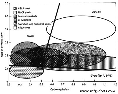 图1 Graville图显示了钢对HACC相对于C含量和CE的敏感性
Graville 图中考虑的 CE 为 CE =% C + (% Mn + % Si)/6 + (% Ni + % Cu)/15 + (% Cr + % Mo + % V)/5。随着钢从 I 区转移到 II 区和 III 区,冷裂纹的敏感性逐渐增加。 Graville 图还显示,主要位于 III 区的可热处理合金钢在焊接时需要特别考虑。 Cr-Mo 和 Q&T 钢也需要小心,正如某些 HSLA 钢所需要的那样。低碳钢很容易焊接,除非在厚部分,为此需要采取一些预防措施。 TMCP 钢经过专门开发,位于 I 区,因此其可焊性非常好。图 1 仅表示可焊性的一个方面,还有许多其他问题,关于 HACC 的理想偏好是使用将成分覆盖层推向 Graville 图左下角的钢。
与电弧焊相关的正常缺陷
孔隙度是由于夹带了小气穴,特别是 H2 和 N2(氮),它们通常在液体中具有更高的溶解度,而不是在固体铁 (Fe) 中。在凝固过程中,气体试图离开焊缝金属。然而,由于高凝固率,一些气体可能会被截留。这种截留取决于气体溶解的速度和焊缝金属的凝固速度。如果溶解速率高,则气泡有机会在钢凝固之前产生和逸出。如果速率低,则气体保留在溶液中,这避免了孔隙率,但会出现其他问题,例如 H2 诱发开裂 (HIC) 或韧性差。在中等速率下,气体会成核,并且取决于溶解在焊缝金属中的气体量和焊缝凝固速率,会产生被捕获的气泡。当气体释放和凝固速率相同时,会出现一种非常严重的孔隙形式,称为虫洞,从而导致形成细长的气袋,而不是基本呈球形的气泡。
H2 的可能来源包括焊剂中的水分、拉丝润滑剂中的碳氢化合物或待焊接接头中的表面污染物,以及“气体保护金属电弧焊”(GMAW)设备中的漏水。 N2 是从由于电弧屏蔽不良而进入电弧区域的空气中收集的。对于 GMAW,当气体流速过低以致横穿气流取代屏蔽或过高以致周围大气被吸入保护气体时,就会发生这种情况。在“保护金属电弧焊”(SMAW)工艺中,当焊工技能不足或使用不当方法导致电弧长度过长时,可能会发生这种情况。
不完全融合可采取多种形式,例如关节穿透不足、根部融合缺失或侧壁融合缺失。这些缺陷可能由以下原因引起:(i) 焊缝能量输入不足,主要是电流不足,(ii) 行进速度过快,导致焊缝金属在电弧之前流动,或 (iii) 电极角度或工作位置不当。
接头熔深和根部熔合的困难通常是由于使用了不适合所使用的焊接工艺的接头设计或忽视了提供足够电弧熔深所需的措施。在大多数情况下,这意味着焊接电流过低。然而,在气体保护焊接工艺的情况下,这可能意味着使用了错误的保护气体。例如,对于富含氩 (Ar) 的气体混合物,穿透模式相对较浅,除了相当深的中央“手指”。不幸的是,这个手指通常不在中心位置,因此不能依赖。然而,富含氦气 (He) 或二氧化碳 (CO2) 的保护气体混合物能够实现更均匀和更深的有用穿透模式。从一侧焊接时发生的根部熔合不良需要修改接头设计以实现更好的熔透或改变从钢件两侧焊接。
在大多数情况下,当焊工没有使用适当的措施或控制技术时,焊缝金属和接头之间的侧壁未熔合就会发生。对于 GMAW 工艺,这可能是由于在焊接重型截面时使用了不适当的变化,例如短路转移。短路转移仅在低能级有效,非常适合在所有位置焊接钢板或薄板。这是因为该工艺旨在提供很少的穿透并快速冻结焊缝金属。由于这个原因,焊缝金属不会在热量快速排出的接头的侧壁上熔化,即厚度超过 6 mm 的接头的侧壁。带有 Ar 的喷射电弧和带有 CO2 保护焊缝的埋地电弧都太大且流动性太大,无法支撑在垂直或顶部位置。然而,这些工艺对于在平坦或水平位置进行焊接非常有效。另一方面,富Ar保护的脉冲电弧变化在所有位置都非常有效,提供了足够的熔深和对熔池的控制,以防止由于侧壁熔合不良引起的缺陷。
热裂纹也称为中心线或凝固裂纹,是由沿约束焊缝中心线的低熔点成分的排斥引起的。它们在焊接完成后立即产生,有时在焊接过程中产生。如果焊缝被破坏以暴露这些裂缝,则会发现它们被发蓝或热着色。这些裂纹通常由硫 (S) 和磷 (P) 引起,更容易出现在高 C 合金钢中。大多数情况下,基础钢板是它们的来源。基于焊缝成分的开裂敏感性已与经验方程进行比较,例如 UCS =230 X % C + 190 X % S + 75 X % P + 45 X % Nb – 12.3 X % Si – 5.4 X % Mn – 1. 如果UCS值小于10,则裂纹敏感性低,而高于30的值表示该敏感性高,值在10-30之间表示需要控制焊接工艺。
缺陷,如焊道中的热裂纹和火山口裂纹,更容易在产生高稀释(即深熔)的焊接工艺或技术中发生。导致中心线开裂的另一个因素是焊坑的尖锐泪滴轮廓,这是高焊接速度的特征。在这些情况下,焊缝凹坑往往会产生收缩裂纹,称为凹坑裂纹。泪珠坑和深熔焊都是通过“埋弧焊”(SAW)工艺和使用 CO2 屏蔽的 GMAW 工艺产生的。这个问题也可能出现在非常凹的角焊缝中,因为它们的横截面可能不足以承受由焊缝收缩引起的横向应力。
在大多数情况下,可以通过将 S 和 P 的总和保持在 0.06 % 以下来防止该问题。然而,当使用高强度钢焊接高约束接头时,通常需要低于 0.03% 的组合水平。当要焊接的钢含有过量的 S 或 P 时,可以通过以下方法避免热裂纹:(i) 使用不会深入穿透的焊接方法或技术,(ii) 选择足够慢的行进速度以防止形成撕裂落坑,(iii)提供凸珠轮廓,以及(iv)填充每个珠子末端的陨石坑。
当通过其厚度施加应力时,在基础钢板中发生层状撕裂,通常在热影响区下方发现。它与包含位于钢板表面下方的薄夹杂物层的带状钢有关。如果要使用脏钢,则可以通过改变接头设计来避免该问题,以最大限度地减少通过焊缝钢板厚度的应变。
咬边是一种不规则的过切,通常出现在水平角焊缝的上趾部。该焊缝部分的钢底板被电弧熔化,但没有被焊缝金属重新填充。 Most often, this defect is caused by improperly selected welding conditions such as the electrode angle, travel speed, and welding current.尝试使用长度超过 8 毫米的支腿进行角焊时,更容易发生这种情况。在 GMAW 工艺中,使用氧气 (O2) 含量低于 2% 的 Ar 屏蔽也会发生这种情况。在垂直位置进行的焊缝中也可以发现咬边,这通常归因于过度编织。
重叠,也称为翻转,通常与角焊缝有关,当焊接电流太低而无法正确熔合基础钢板或行进速度太低而无法接受沉积的金属量时,就会发现重叠。 SMAW 过程中电极处理不当也是一个因素。
夹杂物是由夹在焊道之间的熔渣产生的。它们起源于可能被困在接头中的未熔化的焊剂碎片,或者是允许在电弧前面流动并被焊缝覆盖的熔渣,或者是在焊道之间尚未去除的凝固熔渣,或作为在焊接前尚未从接头上去除的重轧氧化皮。该问题在 SMAW 工艺中最为常见,因为焊工控制技术不佳可能会加剧该问题。当在高度隆起或粗糙的焊缝上进行焊接时,可以预见到夹杂物的存在,因为它们的边缘在焊道之间难以清洁或在焊接过程中难以穿透。可以通过以下方式进行预防:(i) 培训焊工熔敷具有精确平面轮廓的焊缝,(ii) 定位焊缝以允许形成更高能量和更多流体的熔敷物,(iii) 防止焊道之间生锈,以及 (iv)通过清洁或打磨确保焊缝在道次之间得到适当调节。
氢致开裂
氢致开裂 (HIC) 是一种主要与低合金钢焊缝相关的现象。导致 HIC 的因素是 (i) H2 的存在,(ii) 高拉伸应力,(iii) 易受影响的微观结构,(iv) 大约 200 摄氏度和 -100 摄氏度之间的温度,以及 (v) 时间。在较低强度水平(约 490 N/sq mm)下,HIC 通常表现为基础钢 HAZ 中的纵向裂纹,通常称为珠下裂纹。在更高的强度水平(约 830 N/sq mm 或更高)下,焊缝金属也会出现横向裂纹。
常用的表达方式“H2 脆化”表明 H2 会破坏焊缝的韧性,但该术语用词不当。对从裂纹之间区域去除的材料进行的冲击试验表明,该材料表现出的韧性水平相当于在没有 H2 的情况下进行的焊缝,当然,也没有裂纹。但是,拉伸延展性可能会降低,因为在拉伸试验进行时会发生 HIC,这会降低试验样品的横截面积。断裂表面产生的缺陷称为“鱼眼”。冷裂纹是另一种表达方式,用于区分这些裂纹和热裂纹,热裂纹存在于焊缝金属中,由凝固过程中偏析的低熔点成分产生。延迟开裂是另一个正在使用的术语。它是描述性的,因为 HIC 可能几天或几周都不会发生。当预计出现 HIC 时,焊缝通常会在一周或更长时间内不进行射线照相,以使裂纹发展。
机制
氢气是所有弧焊工艺中的普遍杂质。它存在于助焊剂中无法避免的水中、填充焊丝表面的有机润滑剂中、焊接接头中聚集的碎屑中以及可吸入电弧流中的空气中的水分中。 H2 在液态 Fe 中的溶解度高于在固态 Fe 中的溶解度,并且其在固态 Fe 中的溶解度也随着温度的升高而降低。 H2在Fe中的溶解度是温度的函数。
在 1500 摄氏度液相线以上的溶解度按重量计约为 30 ppm(百万分之几),但在固态时约为 8 ppm。在 400 摄氏度时,其溶解度降至 1 ppm 以下。焊接金属的凝固速度非常快,结果,溶解在熔化的焊接金属中的 H2 被保留。虽然作为气体逸出的 H2 通常以小气泡或焊缝金属孔隙的形式被捕获,但大量的过饱和 H2 确实保留在凝固的焊缝金属中。残留物可能看起来微不足道,但应该承认,低至 1 ppm 的 H2 就会导致高强度钢出现开裂问题。
在冷却间隔期间,原子 H2 迅速扩散,一些进入焊缝热影响区,一些逸出到空气中,其余留在焊缝金属内。在适当的条件下,这些高度移动的原子会在金属晶格中寻找裂缝和不连续性,并集中在这些点上。与由于外部约束和凝固和固态转变引起的体积变化引起的晶格中的残余应力相一致,H2扩大了不连续性,形成微裂纹。当原子穿透裂缝并被捕获为分子时,局部应力会突然释放。由此产生的具有尖锐尖端的微裂纹也与额外原子聚集的高应力集中有关。这些应力会不断累积,直到它们也随着裂缝的扩展而减轻。这种应力积累和开裂释放的过程一直持续到 (i) 横截面面积减小到足以导致失效, (ii) H2 逸出的量足以将其浓度降低到开裂进行所需的水平以下, (iii) 焊道下裂纹已将焊缝中的残余应力降低到裂纹继续进行所需的水平以下。
HIC 不会自发发生,而是作为离散的步骤发生。可以在声学上观察到逐步进展。在小样本中,它的进展也可以通过测量电阻的变化来监测。监控描述了 HIC 过程开始后发生的电阻变化,以及 HIC 每次进行一个步骤直到失败的方式。监测还显示了 HIC 对外部压力水平的敏感性。当试样上的应力超过其抗拉强度 (TS) 时,无论是否存在 H2,故障都会迅速发生。然而,当存在足够的 H2 时,由 HIC 引起的损坏可能会在远低于 TS 的应力下引发。如果有足够的 H2 和时间,HIC 可能会导致故障。通常,随着应力的减小,产生裂纹并导致失效所需的时间会增加。
重要的是要知道 HIC 在临界应力以下不会发生。除了施加的应力外,钢中溶解的 H2 量也起着重要作用。随着 H2 的增加,引发 HIC 所需的应力越小,引发 HIC 所需的时间也随之减少。应力和H2这两个变量的交互作用表明,开始HIC的时间和不发生失效的临界应力都与钢中H2的含量成反比。
影响 HIC 的第三个变量是钢的微观结构(焊缝金属或 HAZ)。孪晶马氏体出现在碳含量较高(超过约 0.3% C)的钢中,通常非常困难,尽管所有针状显微组织都可能出现问题,包括贝氏体。这种假设可能是有缺陷的,因为针状微观结构是与高强度钢相关的典型微观结构,而较高的应力本身就是 HIC 的一个加重因素。然而,具有相对宽容的微观结构的钢可以显示出比具有敏感微观结构的强钢更高的临界应力。通常,强度较高的钢对 H2 更敏感,因为 HIC 的起始时间较早,临界应力较低。在高强度马氏体钢和较弱贝氏体钢之间观察到了这种行为差异。
夹杂物也很重要。 HSLA 钢的韧性会受到杂质的影响,尤其是夹杂物。然而,由于夹杂物可以作为 H2 原子的汇,它们也可以产生有益的影响。出于这个原因,一些非常高纯度的钢已被证明对 HIC 非常敏感。不能断定焊缝需要在外部施加应力才能产生 HIC。与熔焊相关的不同收缩总是在焊件中产生残余应力,除了极少数例外,这些应力至少等于接头最薄弱部件的 YS。由于大多数焊缝金属比基础钢强,残余应力接近基础钢板的 YS。通常,可以通过选择较弱或匹配不足的焊接金属来尽量减少关键结构中 HIC 的发展,以保持残余应力尽可能低。对于某些应用,例如涉及疲劳的应用,较弱但健全的结构可能比包含 HIC 的更合适。然而,考虑到敏感的微观结构和足够的 H2,临界应力可能非常低,远低于典型的残余应力。因此,如果 HIC 是一个问题,在大多数情况下,它会在焊接结构离开制造区域之前发展。
另一个重要的观察结果是 HIC 的机制受温度的影响。当温度超过 200 摄氏度时,HIC 的可能性很小。在更高的温度下,H2 扩散率非常高,以使原子集中在晶格缺陷或焊缝中的其他尖锐不连续处。由于H2的流动性基本为零,冷却到-130℃以下的焊缝不太可能发生HIC。
控制 HIC
在考虑 HIC 的冶金要求时,显然可以采用多种方法来避免其发生。这些要求包括减少与焊件相关的残余应力。这些是 (i) 避免焊缝金属和热影响区中的针状显微组织,或至少选择贝氏体而非马氏体的显微组织,(ii) 减少焊接操作期间溶解在焊缝金属中的 H2 量,或 ( iii) 在 H2 造成损坏之前让其逸出。这些方法中最合适的方法取决于要焊接的部件的尺寸、所需的机械性能、可预见的服务、要使用的焊接工艺以及成本限制。在大多数情况下,需要做出妥协,这些方法的组合可能是最具成本效益的。
如前所述,焊缝中的残余应力通常等于接头中最薄弱材料的 YS。在引入高三轴应力的接头配置中,残余应力可能明显高于 YS。尽管设计师很少使用较弱的材料来减少残余应力,但应该认识到 HIC 会对结构的疲劳寿命产生重大影响。为了适应较弱的钢,更可接受的折衷方案是重新设计焊件以合并较厚的部分。然而,可以采取其他方法来充分利用低合金钢的强度而不产生 HIC。
由于焊缝金属或热影响区的微观结构发生变化的可能性很小,除非可以选择不同的钢材,否则应选择最能耐受 HIC 的钢材。另一种减少焊缝残余应力的方法是在低于临界温度的温度下进行焊后热处理。由于钢在较高温度下较弱,因此可以通过将焊缝加热到可能发生塑性屈服的温度来显着降低残余应力。对于具有回火马氏体结构的钢,这种热处理的最合适选择是在其原始回火温度或略低于其原始回火温度,通常接近 620 摄氏度。这种处理称为去应力退火 (SRA)。 For this treatment to be effective, the weldment is to be kept in a suitably large furnace before its temperature drops below 200 deg C and then, to prevent difficulties related with distortion, heated and cooled slowly. Considering the temperature and time required for the SRA treatment, it is obvious that all of the diffusible H2 in the weld will escape. However, unless the stresses in a weld are to be relieved for reasons other than the avoidance of HIC, SRA can prove to be a very costly option. Post-heating also has a place in the scheme of preventing HIC. It is not necessary to reheat weldment to temperatures which are much higher than 200 deg C in order to accelerate the escape of H2 and still avoid the temperature range within which HIC is likely to occur. Such thermal treatments are good for welded components which are small enough to be preheated in a furnace prior to welding and returned to the furnace immediately after welding for a period of time which allows all of the H2 to escape. This approach is mainly important for very high strength alloy steel, which is very sensitive to cracking problem connected with H2.
Similar result is possible by slowing the rate at which weld is allowed to cool after welding. This provides more time for H2 to escape before temperatures drops below 200 deg C. Retarding the cooling rate also allows the transformation of austenite to softer microstructures that are less sensitive to HIC.
The cooling rate of arc welds is affected mainly by three factors namely (i) the temperature of the joint before welding begins, (ii) the arc energy input during welding, and (iii) the joint thickness. The initial temperature can be the ambient temperature of the area where the steel has been stored, or the temperature to which the weldment has been heated as the result of a previous weld by external methods (the inter-pass temperature), or the temperature to which the joint had been heated (the preheat temperature). As preheat temperature is increased, the cooling rate decreases. The arc energy input is defined by the electrical energy dissipated by the arc and the speed at which the arc is moved along the joint. Higher arc energy input retards the cooling rate.
The joint thickness also affects cooling rate since most of the heat entering the joint is extracted by conduction into the body of the weldment. Conduction is at a maximum with three-dimensional cooling. This occurs when the joint is thicker than around 25 mm. Conduction is less effective in thinner sections, which means that the weld cooling rate is inversely proportional to the thickness. Though the cooling rate of thin section is also influenced by radiation and convection, the effect is much less pronounced than that of conduction.
The variables described above can be incorporated into a single equation which allows calculations to be made of the rate at which weld cools at a specific temperature. CRt =K [(T-To)2 /E] where CRt is the cooling rate at temperature T, K is a constant of proportionality (including an adjustment for the steel thickness, if it is thinner than 25 mm), To is the preheat or inter-pass temperature, and E is the arc energy input, which is calculated as E=VI/S where V is the arc voltage, I is the welding current, and S is the arc travel speed. By combining the above two equations, a general expression for cooling rate is obtained which is CRt=K [(T-To)2*S/VI]. This equation has been developed for the purpose of predicting weld and HAZ microstructure in conjunction with continuous-cooling transformation diagram. This diagram allows the determination of the cooling rates above which strong martensite or bainite are ensured or below which they can be avoided. The same equation can be used to calculate the cooling rate at temperature critical to the evolution of H2 and the avoidance of HIC.
The adjustment of welding procedures is accomplished by varying the current or the travel speed. Voltage is a strongly dependent variable which is determined by (i) the welding process, (ii) the characteristics of the electrodes, fluxes, or shielding gases, and (iii) the current. It is not to be viewed as a variable with which to control weld cooling rate.
The other method of retarding cooling rate, which is possibly the most common method, is to control the preheat temperature or inter-pass temperature of the joint prior to welding. Relatively small changes in these temperatures can exert strong effect on cooling rate at temperature around 200 deg C, which is critical with regard to the onset of HIC. As an example, by increasing the preheat temperature from 20 deg C to 100 deg C, the cooling rate at 200 deg C is reduced by around one third. By preheating to 150 deg C, the cooling rate is reduced by a factor of around ten, which is a very significant amount when fabricating high strength steel which has little tolerance to HIC.
Preheating is rather costly. It can affect the weld microstructure and can make working conditions intolerable for the welder. However, preheating is vital for reducing HIC. Preheat affects the lower critical stress in the HAZ of high strength steel when welded with a covered electrode. The ultimate TS of this high strength steel is around 750 N/sq mm. Yet, with a 25 deg C preheat which is the room temperature; failure is caused by HIC in less than 10 min at a stress level of around 490 N/sq mm. The lower critical stress below which failure does not occur is around 415 N/sq mm. By preheating to a temperature of 120 deg C, the critical stress is increased to 620 N/sq mm, which is around the YS of the high strength steel, but still considered unsafe. To avoid HIC entirely, under the conditions used to produce the weld, the preheat temperature need to be higher than 150 deg C.
A number of approaches have been used to select the most appropriate temperature for preheating steel for the avoidance of HIC. Some approaches rely on empirically derived tables which list the steels and recommended welding measures, including those for preheat and post-heat. Another relates cracking tendencies quantitatively to the hardenability of the steel, calculating it on the basis of the CE. One such formula for CE is given by the equation CE =C + Mn/6 + Si/24 + Ni/40 + Cr/5 + Mo/4.
For application which involves weld to be made with covered electrode, the recommended preheat temperature for steels having different CEs although show a considerable scatter, yet the overall trend demonstrates a linear relationship between the CE and the preheat temperature. For a quick approximation of the required preheat, the relationship To =200 CE can be used, where To is in deg C. For including the scatter band which incorporates all of the data points, a more-precise interaction between the CE and the preheat temperature can be shown by relationship To =210 CE (+15 to -45). The scatter band of 60 deg C is quite large, which suggests that the upper portion be used for selecting suitable preheat temperatures with which to avoid potential problems. However, if metallurgical softening needs to be avoided, then the most appropriate course of action is to rely on laboratory trials for determining the minimum effective level of preheat. Of course, such a determination needs that the energy input, the thickness of the joint, and the welding process is also to be considered.
Measurement of H2
Direct measurement of H2 in weld metal is difficult. Unless good care is taken to stop its escape from a weld before an analysis can be made, the amount measured is not generally the representative of that which might have caused a crack to develop. This means that sample is to be planned to be analyzed quickly or super-cooled in liquid nitrogen (N2) to stop the diffusion of H2 while awaiting analysis. The technique recommended by the American Welding Society (AWS) measures the volume of H2 gas which escapes from a test weld which is around 75 mm long. It is collected in either a eudiometer tube (in a mercury or glycerine bath) or in the isolation chamber of a gas chromatograph.
Indirect methods also have been used by measuring the sources of the H2. For wires used in the GMAW and SAW processes, this can be done by measuring the hydrocarbons on their surface. Mass spectrometry can be used for the analysis. For the SMAW and SAW processes, the moisture adsorbed in the fluxes can be determined. Often, this is done by measuring weight loss after drying at high temperatures of around 400 deg C to 425 deg C. The issue related with indirect measurements is that the efficiency of transfer of the H2 to the weld from the wires or fluxes is difficult to predict. It is normally dependent on the welding technique. Hence, empirical results are used to relate the amount of H2 present in the welding materials to the HIC in the weldment. For this reason, a comparison among processes becomes very difficult. However, even the measurements of gas evolution can be faulted, since only the diffusible H2 is measured. Some remains in solution and some are trapped within weld defects or inclusions.
Importance of welding process
The arc welding process needs a source of filler material and methods for protecting and controlling the arc and the deposited metal. In most of the cases, the filler material is provided in the form of rods, continuous wires, or continuous tubes. The surface of all of these materials is contaminated with residue of H2 rich drawing lubricant. In the GMAW process, a shield gas is used for protection. For cored wire, a combination of shield gases and fluxes are used. The submerged arc and covered electrode techniques involve only fluxes. All of the fluxes are sources of chemically combined or adsorbed water. The quantity of H2 dissolved in weld metal can vary, not only between but within processes.
Of all of the arc welding processes using consumable electrode, the GMAW process is associated with the lowest H2 levels, the primary source being residual drawing lubricant on the wire surface. Totally dry wire is unacceptable, because it is difficult to feed. The amount of residual lubricant generally is not a problem with steel having YS less than 520 N/sq mm. However, as the YS approaches 620 N/sq mm, the residual lubricant becomes a potentially important factor if HIC is to be avoided, unless relatively high preheat temperature can be used. When the YS exceeds 830 N/sq mm, the residual lubricant is to be kept as low as possible.
The importance of the residues is reflected by the effects of H2 on HIC in welds which have YS of 930 N/sq mm and which need to be minimized by controlling the cooling rate. In this case, the cooling rate is determined at 540 deg C, a temperature close to that at which the weld metal transforms from austenite to martensite. At the relatively rapid cooling rate of around 30 deg C/second, 4 ppm of H2 on the wire surface is shown to have caused HIC. To be securely free of HIC, the H2 is to be maintained at level below 3 ppm. By adjusting the welding technique, preheat temperature, or both, in order to retard the cooling rate at 540 deg C to less than 20 deg C/second, the tolerance for H2 on the wire can be increased to 5 ppm.
As stated under H2 measurements, it is difficult to predict the amount of H2 which gets transferred to a weld from surface contaminants that are decomposed in the arc (or before reaching the arc), mainly when the level is measured in single digit ppm. This level is so low as to prevent the use of gas evolution technique for the measurement of the H2. The higher tolerance for wire surface contaminants at lower cooling rate can be due as much to the softer microstructure as it is to the escape of H2. To retain high strength, the higher cooling rate is necessary. Usually there is a very sudden drop in strength as the cooling rate drops below 10 deg C/second. Obviously, to obtain the strongest possible weld without encountering HIC, it is necessary to minimize the presence of any contaminants that contain H2.
The achievement of very low level of H2 is not possible with any of the other arc welding processes, because they need fluxes instead of shield gases for protection. Fluxes can absorb water. There is the importance of moisture in a submerged arc flux on the cracking sensitivity of a weld metal which has YS of 830 N/sq mm. It shows that diffusible H2 level as low as 7 milli-litres/100 grams can drop the critical strength to 105 N/sq mm (H2 content of 1 ppm is equivalent to 1.11 milli- litres/100 grams). Even baking the flux to reduce the weld-diffusible H2 below 2 milli-litres/100 grams does not eliminate HIC. The critical stress remains below 415 N/sq mm. It is obvious that the welding conditions used for the submerged arc weld are not acceptable. Either the steel is unusually sensitive to H2 or the flux used is not capable of being dried sufficiently to reduce H2 contamination.
Similar HIC problem is encountered in the SMAW process when weld strength exceeds 480 N/sq mm. For this reason, low H2 electrode has been developed specifically to minimize, if not prevent, the problem. Low H2 electrode coating is formulated without any organic material. This low H2 coating is baked at temperature exceeding 430 deg C to reduce residual moisture to a level of around 0.1 %. This is nearly the lowest practicable level, since the absence of moisture in a coating tends to make it brittle. The effect of baking on the residual moisture during initial manufacture shows that even with careful control of formulation and baking, the moisture level of covered electrode coating cannot be reduced to levels sufficiently low to prevent HIC in steel having YS higher than 830 N/sq mm.
The moisture in low H2 electrodes usually is specified as 0.2 % max. This moisture level is what is expected to be found in coatings of commercial low H2 electrodes, immediately after being removed from hermetically sealed containers. However, if exposed to humid, warm air, thee electrode coating reabsorbs moisture. The rate of moisture pickup depends on the constituents in the coating. In some cases, reabsorbed moisture can reach levels exceeding 1 %. For this reason, electrodes are to be stored in heated ovens on hot and humid days and exposed to shop atmospheres only for short times.
Moisture-resistant coating has been developed to counter the reabsorption problem. Although the coating is quite safe when exposed to the relatively cool and moderately humid atmosphere indicated, extra precaution is necessary when welding in tropical conditions. It is possible to salvage electrodes which have become ‘wet’ by re-baking them at temperatures which approach those used during their manufacture. Drying time of around 1 hour is typically needed to recondition electrodes at around 400 deg C to 425 deg C. Although re-baking can salvage electrodes which are inadvertently exposed to moist conditions, the process is not to be repeated since the covered electrodes are alloyed with metal powders which can be oxidized during re-baking operations. Hence, the resulting alloys are leaner and weaker.
Re-baking causes a loss in both Mn and Si content of the weld metal, resulting in a drop in the weld YS. This happens with very controlled re-baking. Unfortunately, the same care is not always taken in shop atmospheres. Significantly greater losses in the Mn and Si contents, as well as mechanical properties, can be expected.
制造工艺