

智能上拉栏
组件和用品
 |
| × | 1 | |||
| × | 1 | ||||
| × | 1 | ||||
| × | 1 | ||||
| × | 1 | ||||
 |
| × | 1 | |||
 |
| × | 1 | |||
| × | 1 | ||||
| × | 1 | ||||
 |
| × | 1 | |||
 |
| × | 1 | |||
| × | 1 | ||||
 |
| × | 2 | |||
 |
| × | 3 | |||
 |
| × | 4 | |||
| × | 1 | ||||
| × | 1 | ||||
| × | 1 | ||||
| × | 1 | ||||
| × | 1 | ||||
| × | 1 |
必要的工具和机器
 |
| |||
 |
|
应用和在线服务
 |
|
关于这个项目
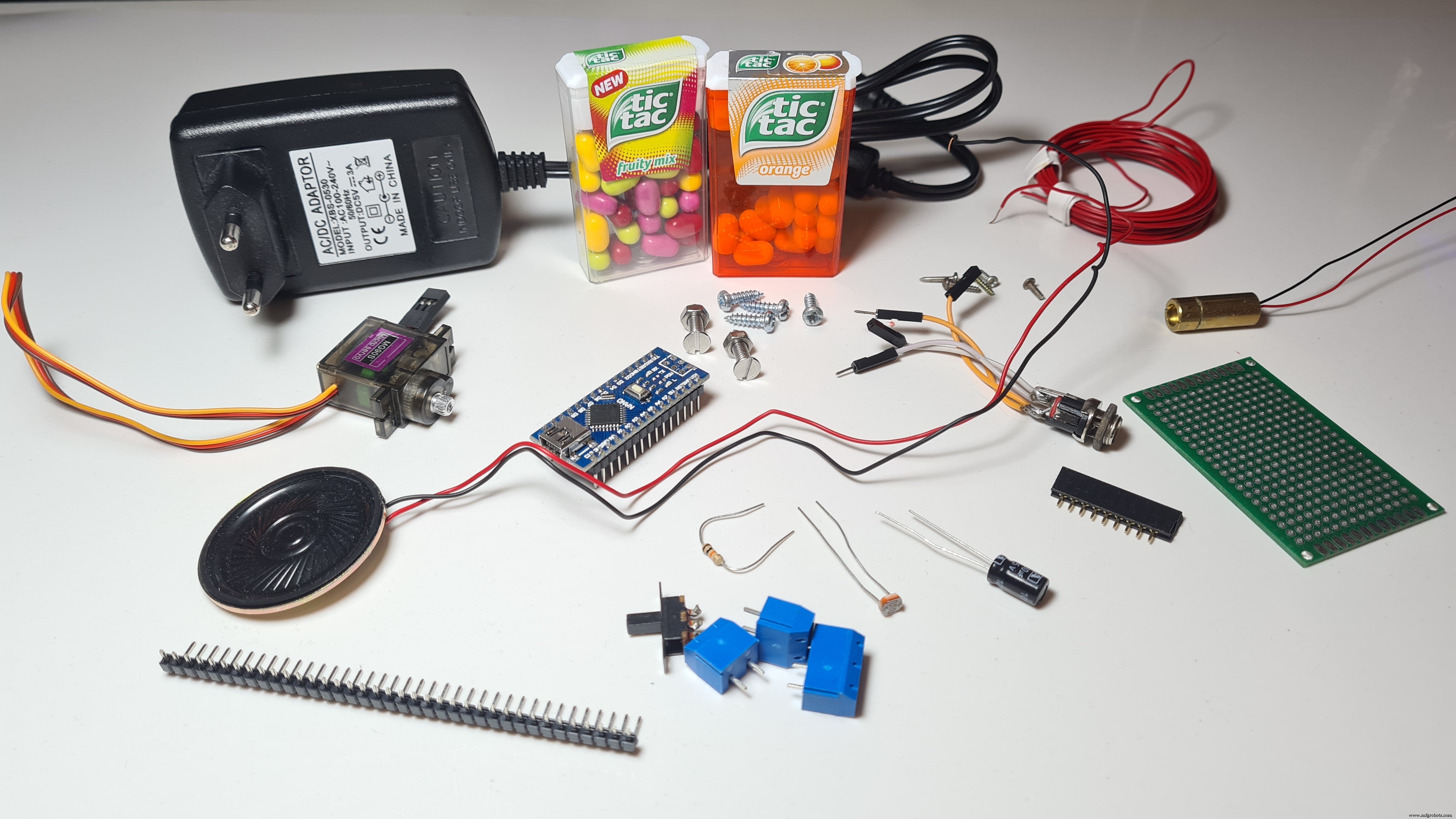
你好朋友!我叫尼古拉斯,今年 15 岁。今天在本教程中,我将向您展示如何使用 Arduino Nano 制作智能上拉杆 其中,当你开始做引体向上或引体向上时开始播放音乐 为了让你保持动力,在锻炼一段时间后,奖励 ,井字 ,在我的情况下被分配!请务必观看上面的 YouTube 视频 看看 Smart Pull-Up Bar 的运行情况,如果您愿意,可以按照那里的说明进行操作!
本来想做这个是为了激励自己多锻炼,结果只是想找个借口多吃点糖果!
此外,我真的要感谢 Arduino,因为这个项目被选为 获胜者之一 2021 年 Arduino 日社区挑战 !
第 1 步:了解其工作原理

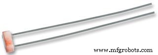
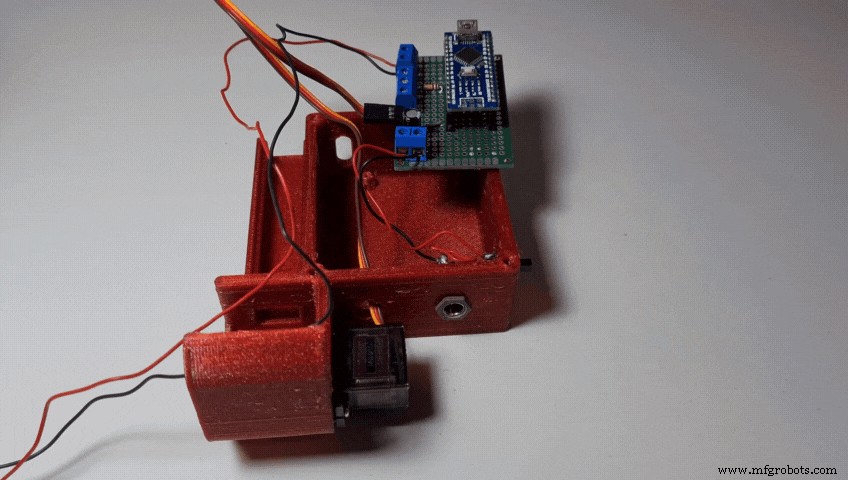
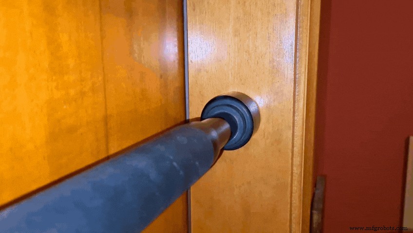
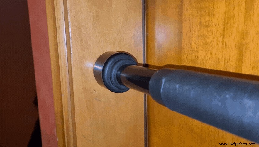
基本上我做了一个激光束传感器 通过连接便宜的激光二极管 和一个 LDR 在引体向上杆上。它们完美对齐,这意味着大量光到达 LDR,因此传感器输出高模拟值。然而,一旦我将手放在杆上开始锻炼我挡住了光束,该值就会显着降低,并且传感器会向安装在外壳中墙壁上的 Arduino Nano 发送信号,然后开始播放歌曲使用小型扬声器(就我而言,它是 Take on me 由啊哈)。大约 30 秒后,当歌曲结束时,如果我的手仍然放在吧台上,则奖励,Tic Tac 使用由伺服旋转的 3D 打印机构分配!
现在您了解它的工作原理让我们开始制作它 !
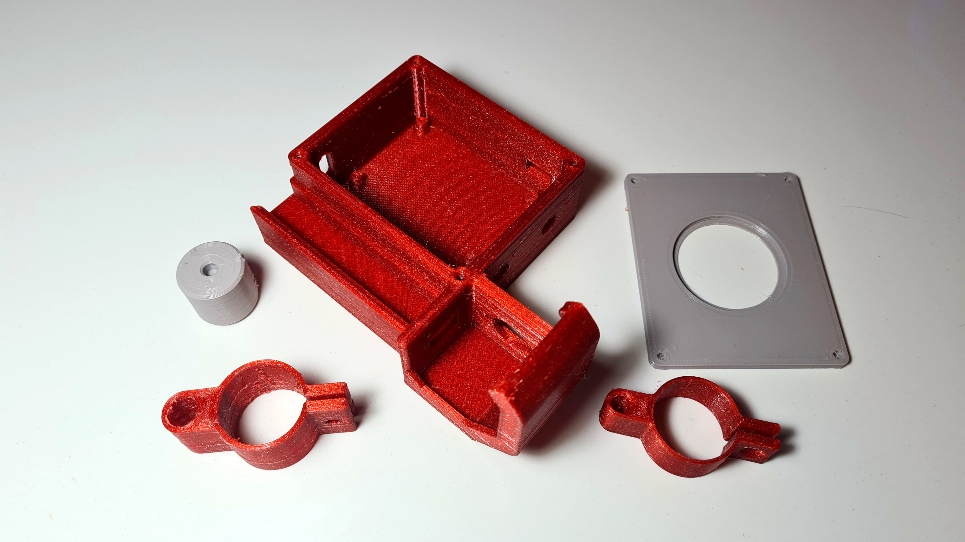
第 2 步:3D 打印
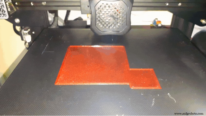

我在 Fusion 360 中设计了所有部件,在 Cura 中将它们切片,然后用我的 Ender 3 V2 在 PETG 中以 0.2 毫米的层高打印它们。您需要打印:
- “Base.stl "
- “RotatorDispenser.stl "
- “CoverBase.stl "
- “LaserClamp.stl "
- 还有“LdrClamp.stl "
您可以在此处找到所有文件
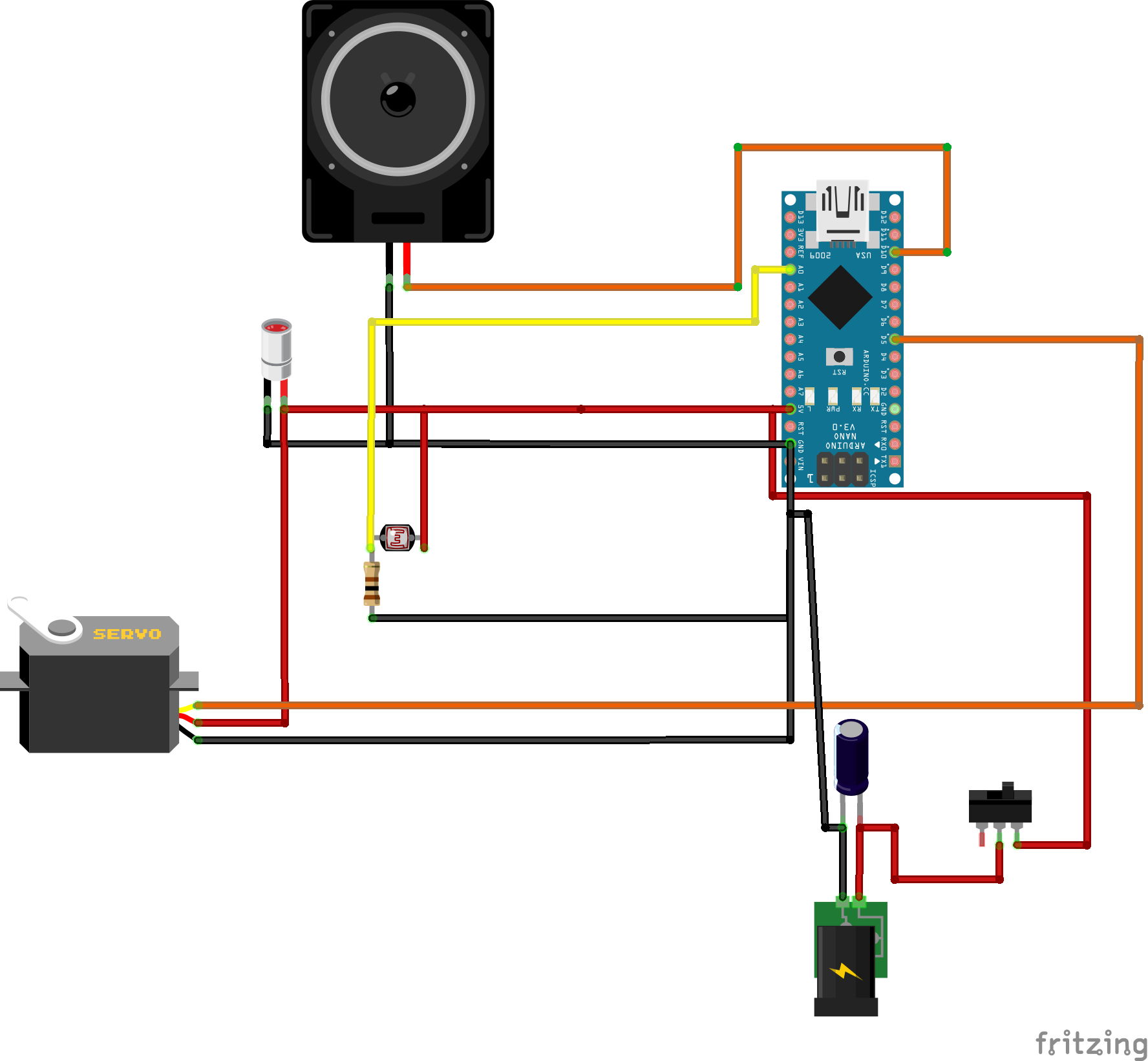
第 3 步:电路第 1 部分

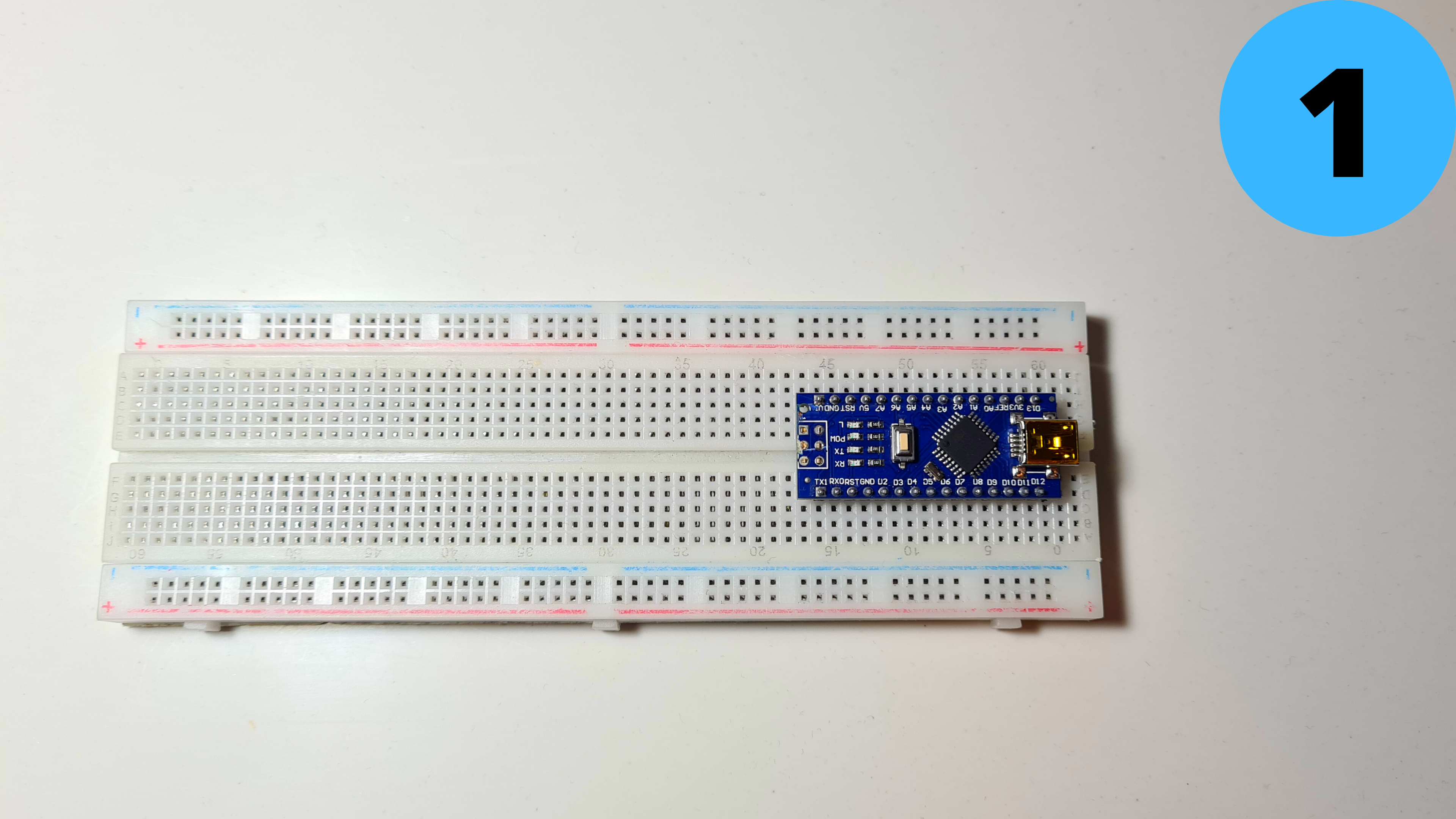
是时候连接电子设备了!!
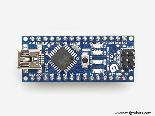
1. 将 Arduino Nano 放在面包板上
2. 连接5V 到正极(红色)和 GND 负轨 (蓝色)
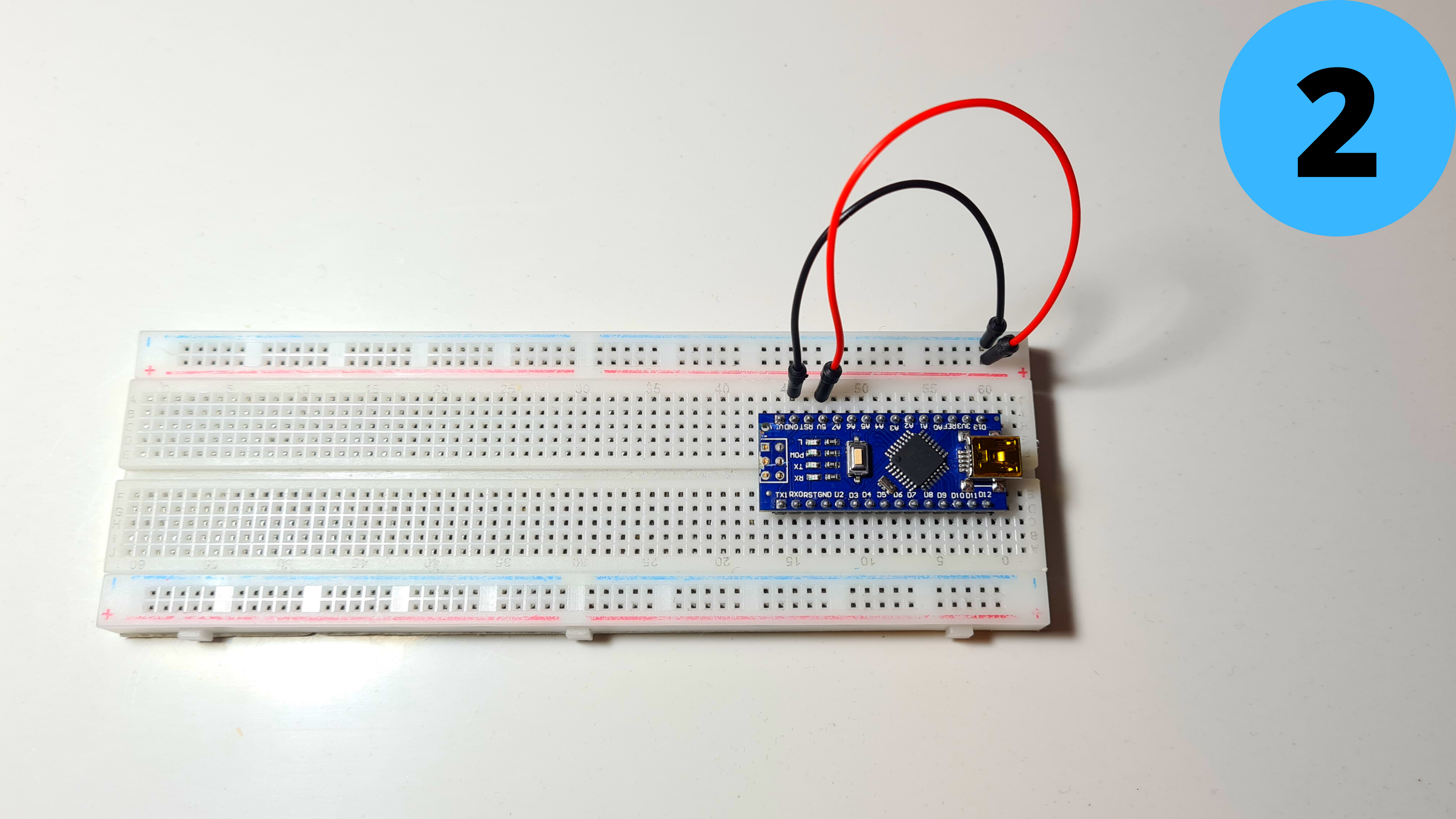
第 4 步:电路第 2 部分
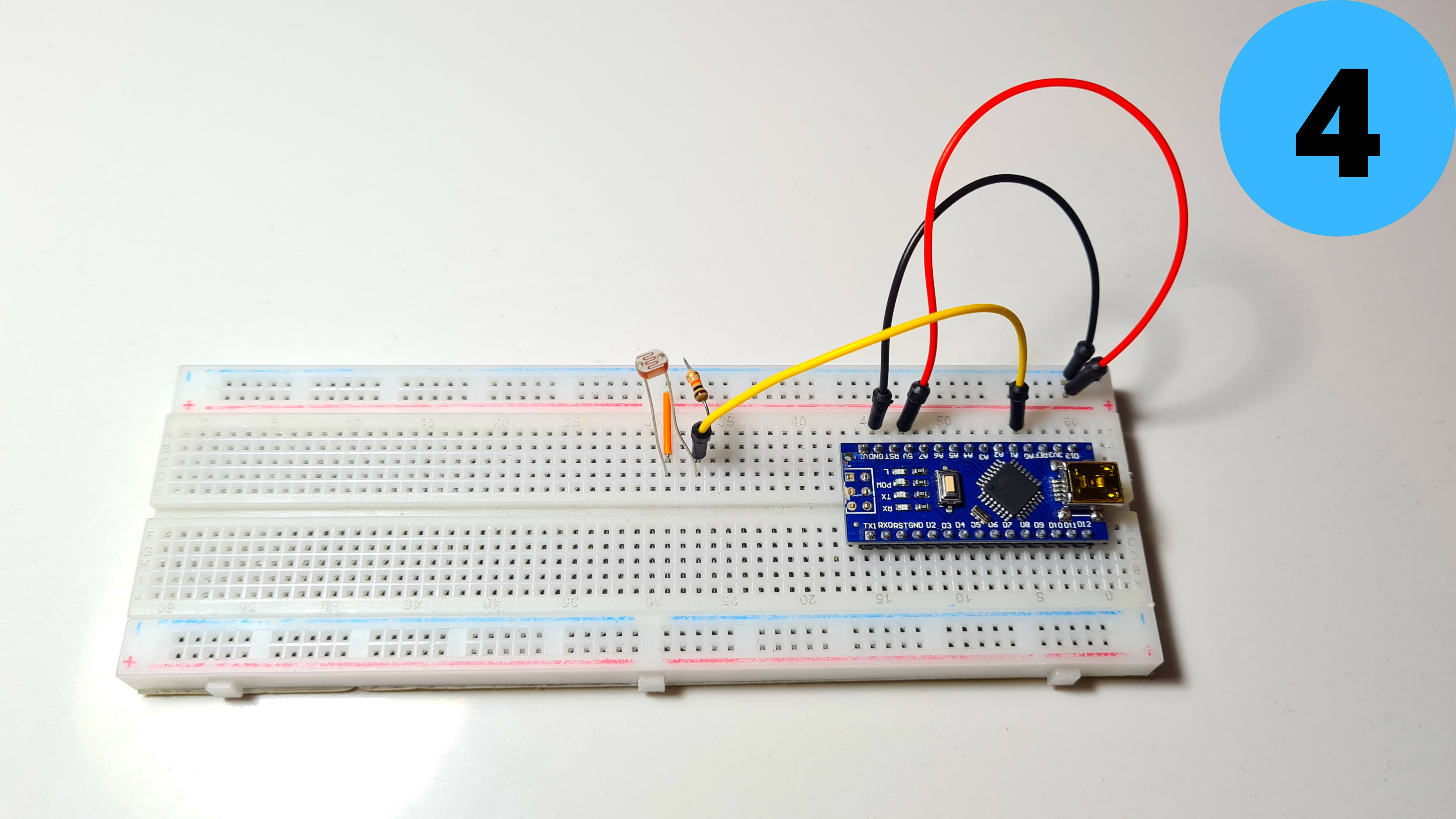
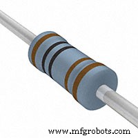
3. 添加LDR 并连接它的一个潜在客户 到 5V 而另一个 到地 使用 1kΩ 电阻 (顺序无所谓)
4.将第二个引线也连接到A0
5.添加MG90S舵机,棕线接GND,红线接5V
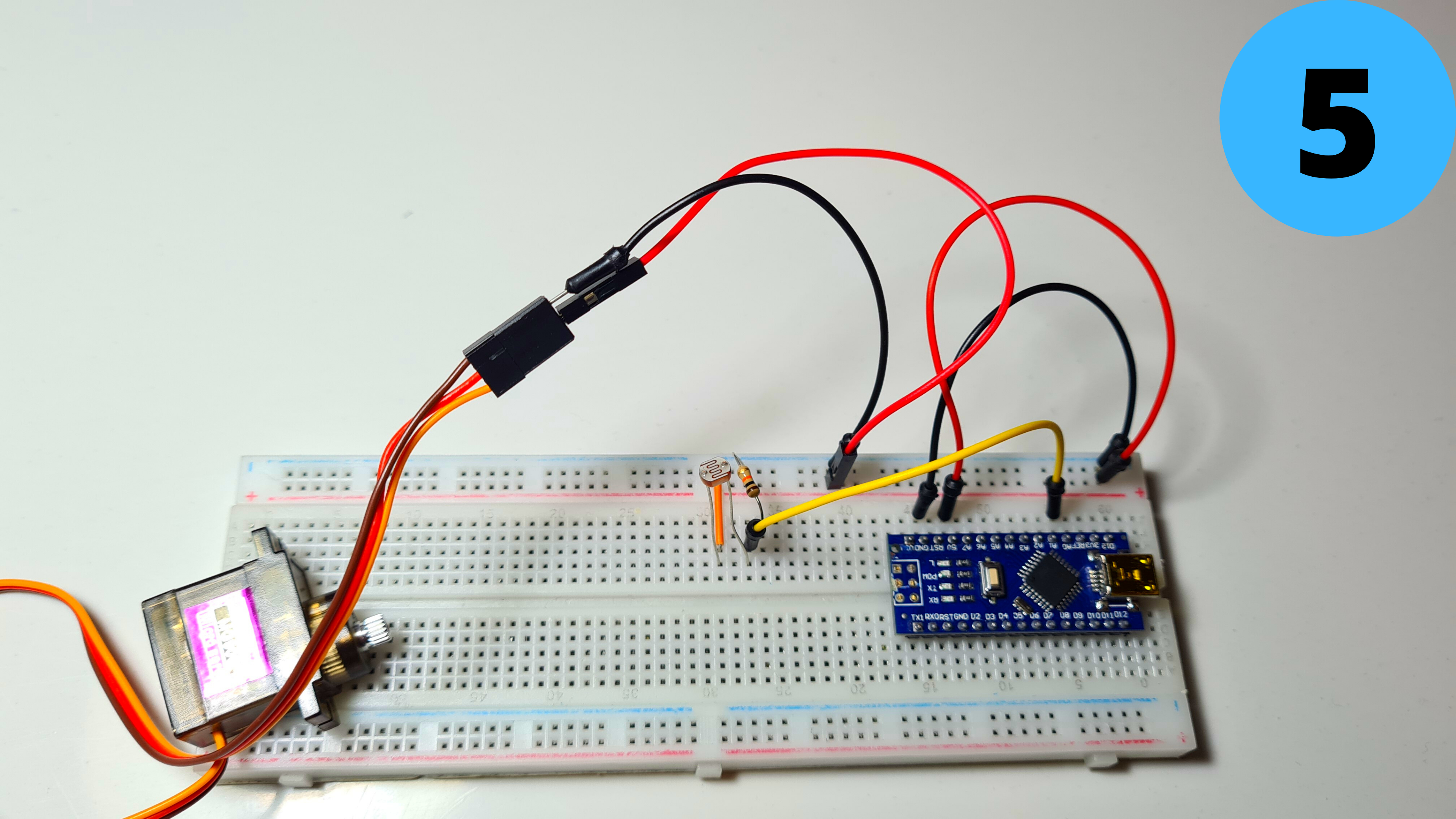
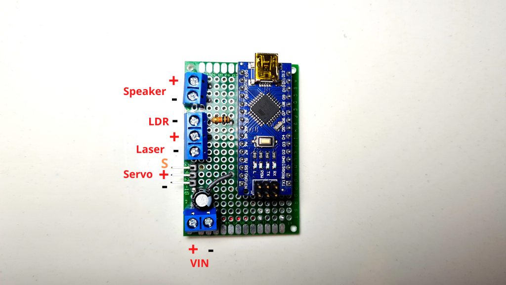
第 5 步:电路第 3 部分
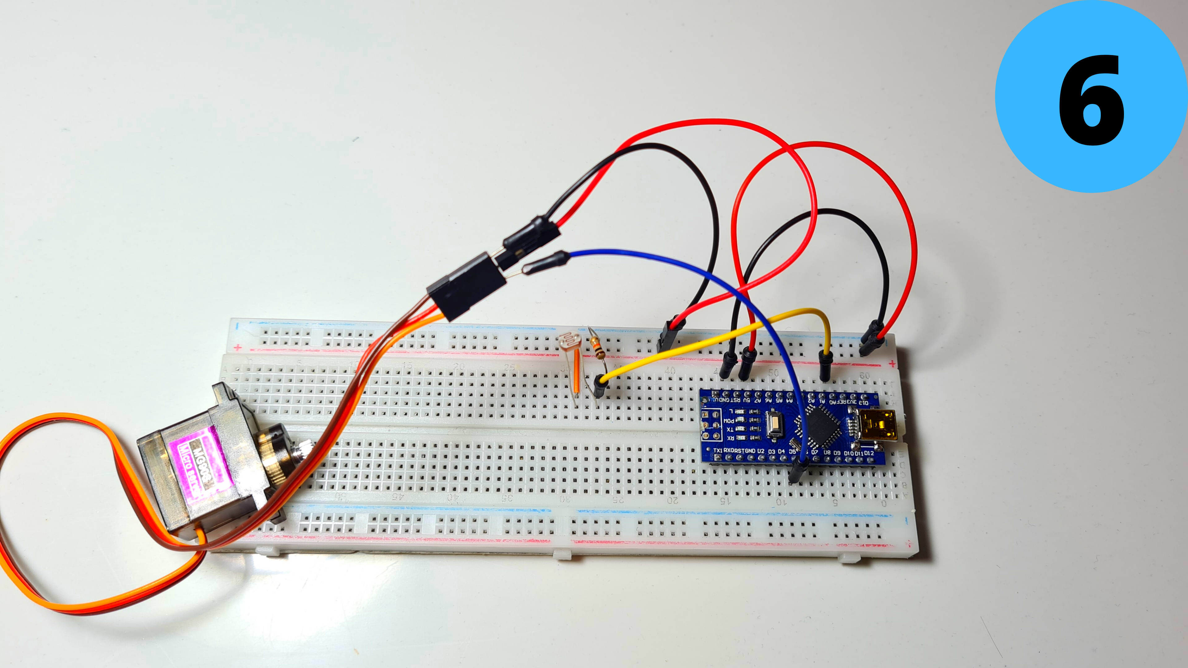
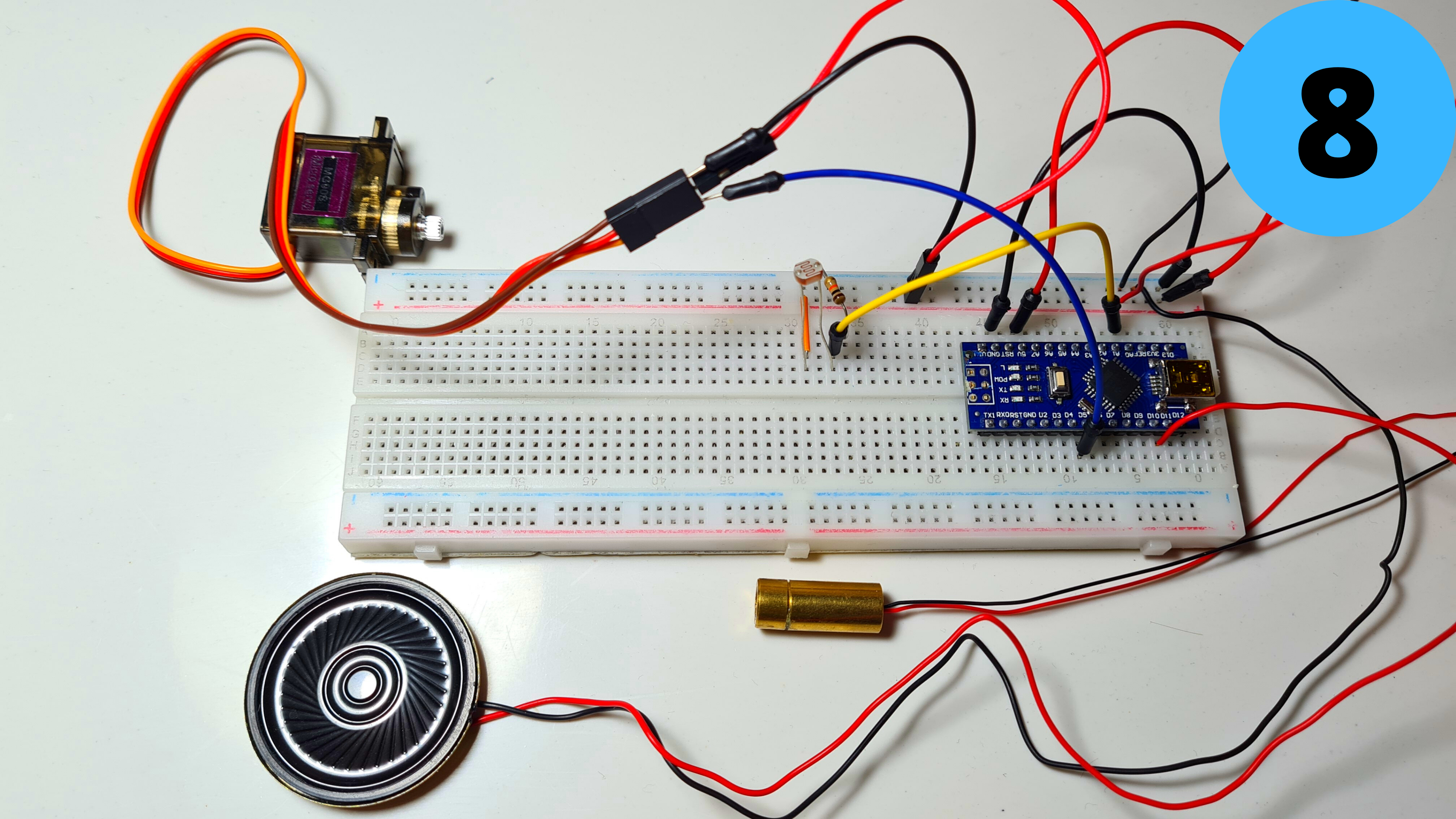
6. 连接黄线 到 D5
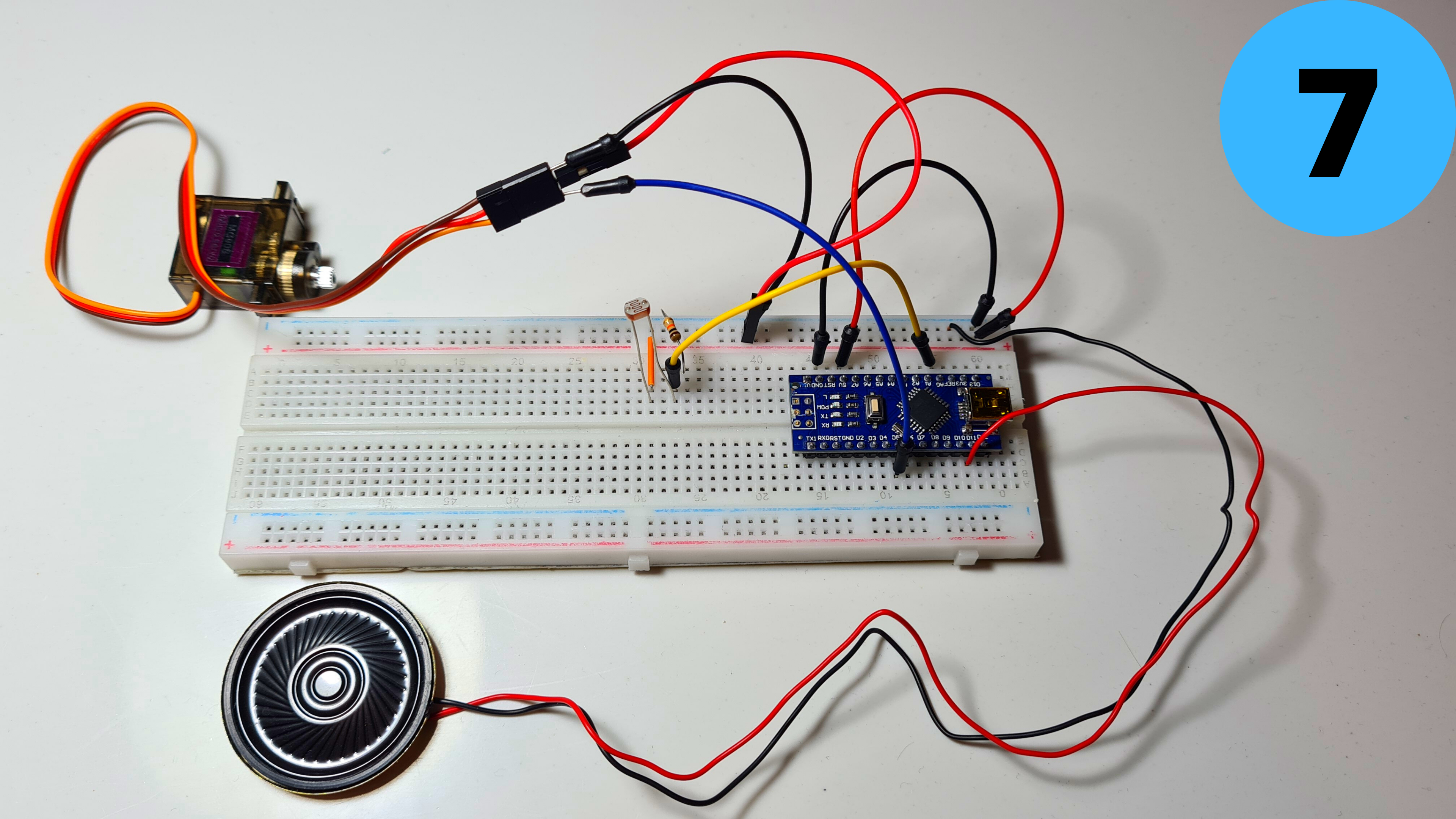
7. 添加小喇叭 并连接它的红线 (+) 到 D11 和它的黑线 (-) 到 GND
8. 最后添加激光模块 并将其红线 (+) 连接到 5V 及其 黑线 (-) 到 GND
第 6 步:编程
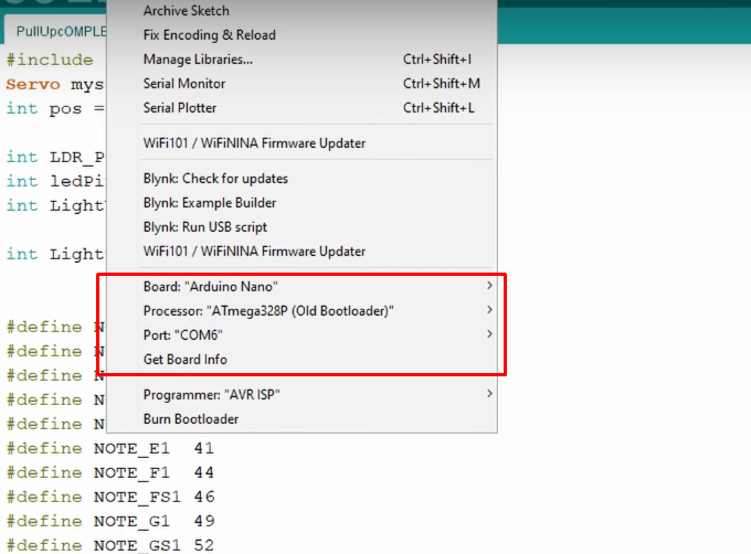
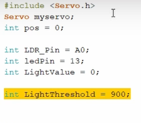
是时候为 Arduino Nano 编程了!我在下面附上了我的代码供您下载。打开 Arduino IDE 选择 Arduino Nano Board , 您的 COM 端口 ,点击上传 你就完成了! 光阈值 定义了 LDR 对光线的敏感程度,请记住这一点,因为我将在下一步中更深入地研究它。
也来看看adithyalokesh17的作品吧!他已经将很多流行歌曲(比如我用过的“Take on me”)变成了轻量级的 Arduino 代码,它易于与蜂鸣器和扬声器一起使用,无需任何复杂的 SD 卡读卡器等。
第 7 步:测试/故障排除
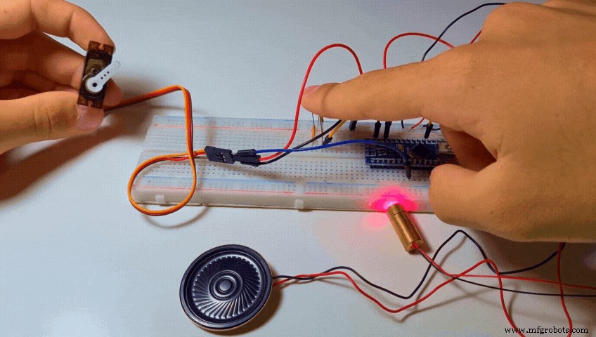
当代码被上传时,什么也没有发生。然后我用手指盖住 LDR,以阻挡光线到达它。几乎模拟了锻炼期间当我的手挡住激光束时会发生什么。在这两种情况下,If 语句都被触发,音乐开始播放,然后伺服旋转并分配一个 Tic Tac。
即使你做的一切正确,这里也有两个常见的问题。
- 当您覆盖传感器时,音乐不会开始播放。您可以通过增加轻松解决这个问题 我们在上一步中讨论的“LightThreshold”值,从而使其更加敏感。
- 音乐开始播放,甚至没有覆盖传感器。你可以解决这个减少 “LightThreshold”值,从而降低敏感度。
提示:
- 正确调整阈值的一个好技巧是使用串行监视器并查看传感器产生的光值。 (范围可以介于 0(绝对暗度)到 1023(绝对光度)之间
- 为了获得准确的测量结果,我建议将激光二极管对准 LDR 并使用这些值而不是您房间的环境光值。
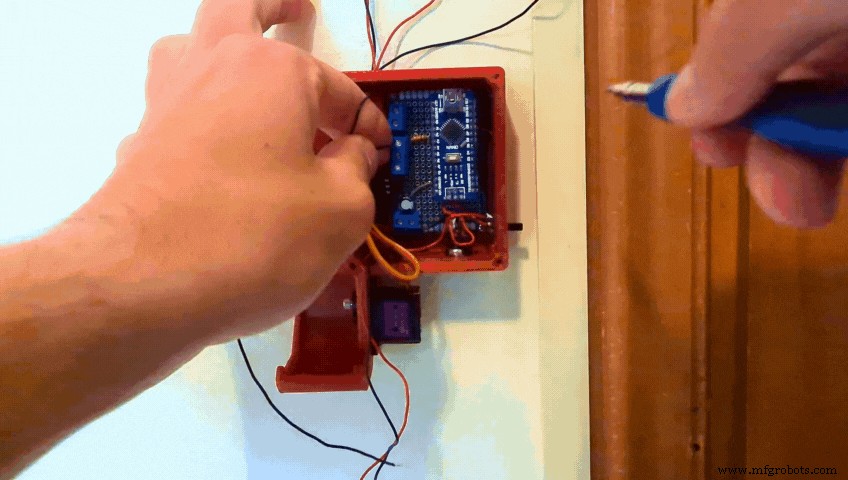
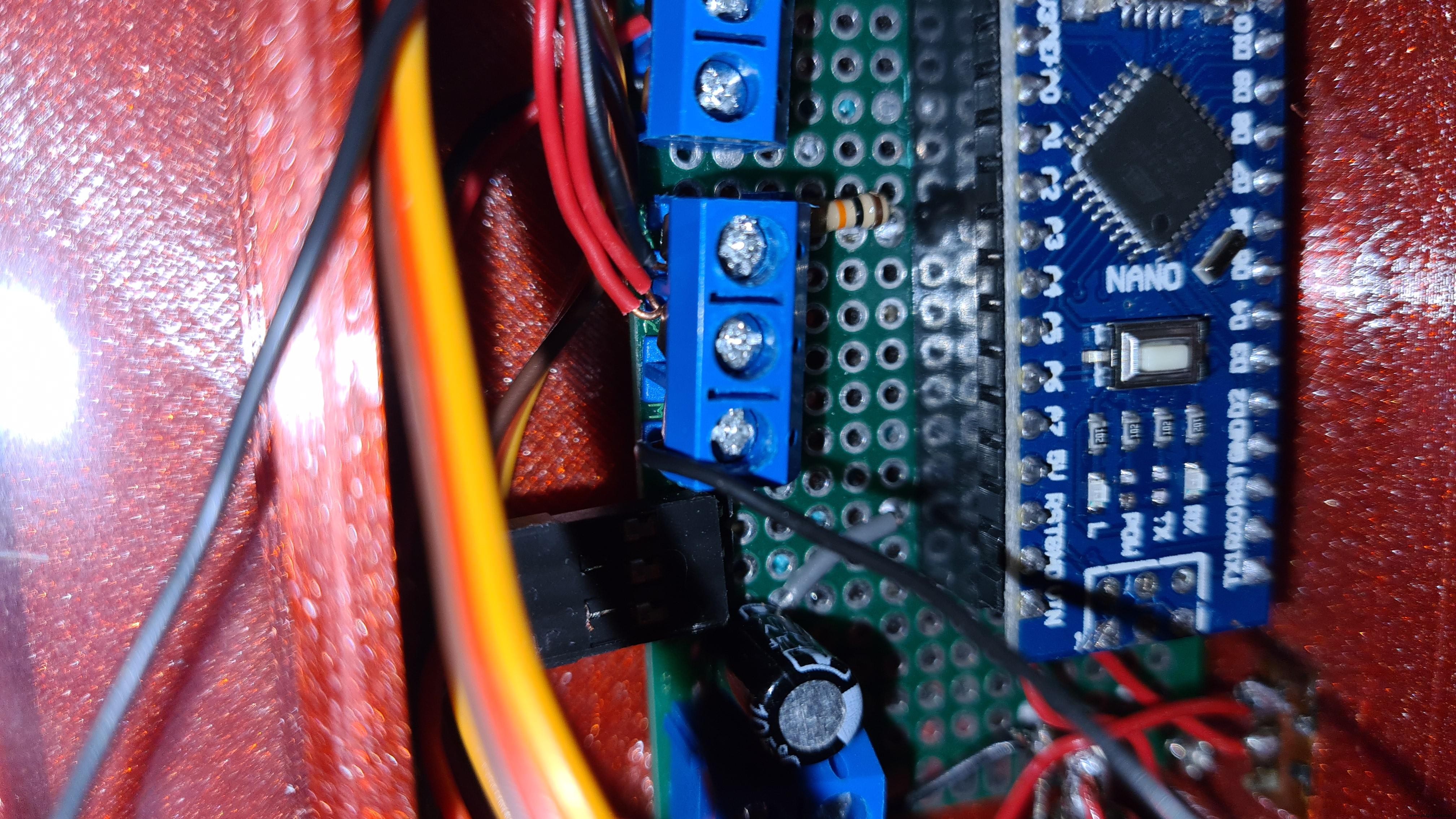
第八步:印刷电路板
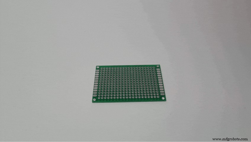

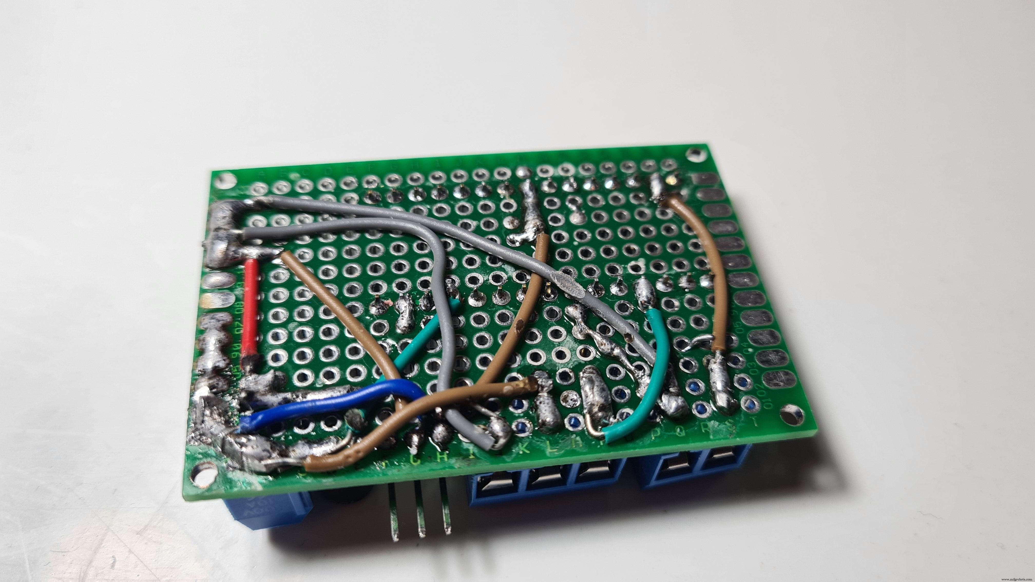

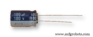
由于一切正常,是时候制作 PCB 以将所有组件安装在更紧凑的外壳中。 PCB 与我们之前制作的面包板电路的唯一区别是,我包含了一个电源输入端子,该端子将 (+) 连接到 5V 并将 (-) 连接到 GND,并且我添加了一个 100μF 电容器(可选)以并联以平滑出电流。
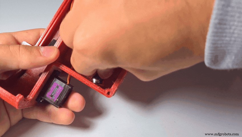
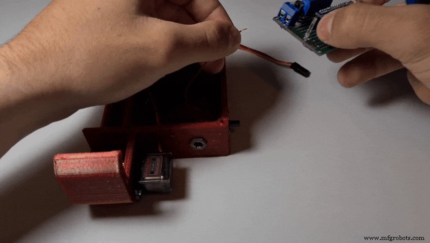
第 9 步:连接舵机
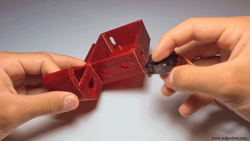
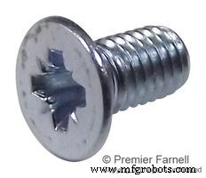
- 使用 1 或 2 个 M2 螺钉将伺服器拧到底座上。
第 10 步:将激光器推入夹具
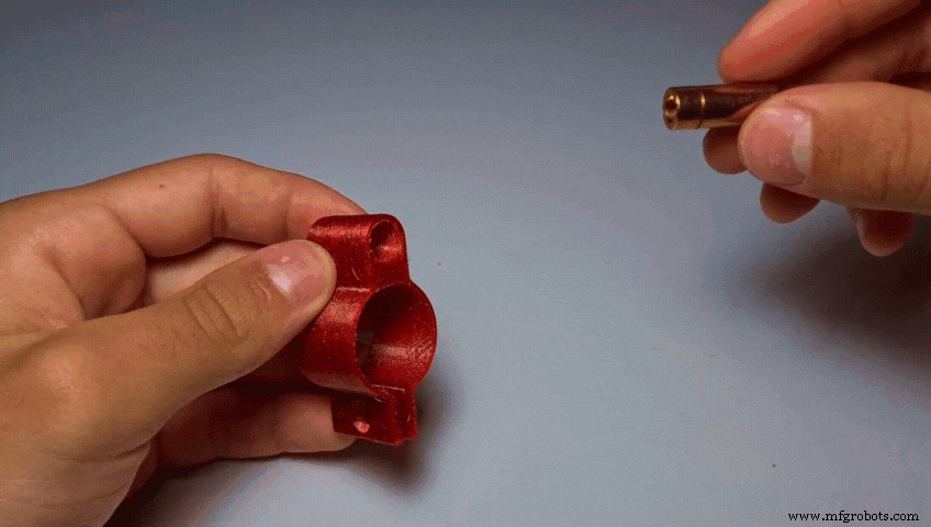
- 将激光二极管推入激光夹。
第 11 步:将 LDR 连接到夹具

- 将 LDR 插入 LdrClamp。 (有两个小孔可以让电线穿过)
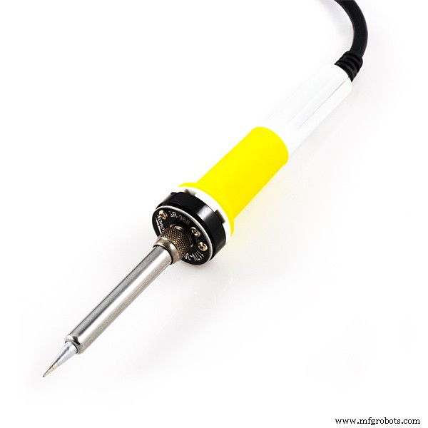
第 12 步:焊接
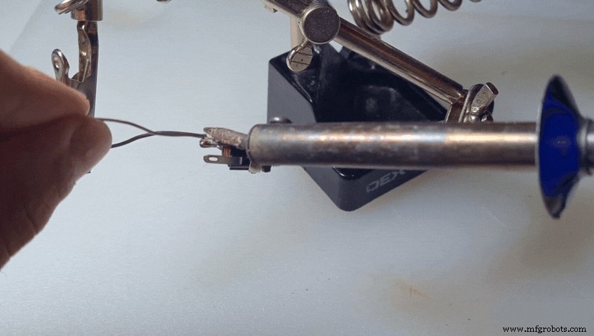
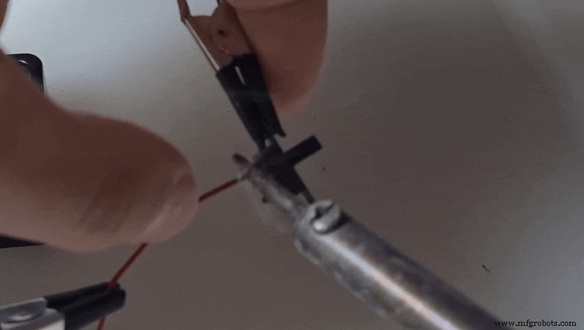
- 将最好是红线焊接到 DC 插孔的正极。
- 将一根黑线焊接到 DC 插孔的负极引线上。
- 将一根新的红线焊接到滑动开关上。
第 13 步:连接 DC 插孔
- 将 DC 插孔插入底座的孔中。使用螺母将其固定到位。
第 14 步:焊接开关
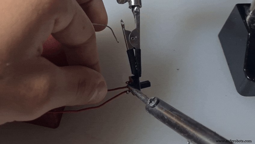
- 将 DC 插孔的红线焊接到开关的另一根引线上。
第 15 步:连接开关
- 将开关推到位。
步骤 16:将电源连接到 PCB

- 将红线连接到 PCB 的正极电源输入端。
- 还有连接负电源输入的黑线。
第 17 步:将伺服连接到 PCB
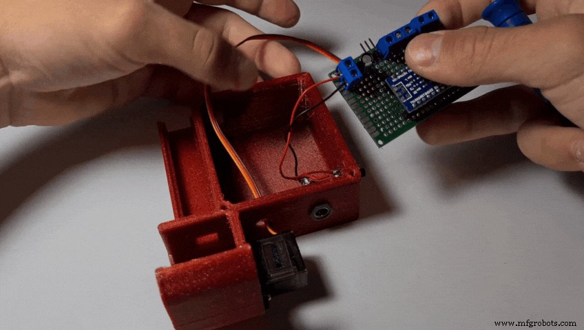
- 将伺服器连接到公头。
第 18 步:将扬声器连接到 PCB
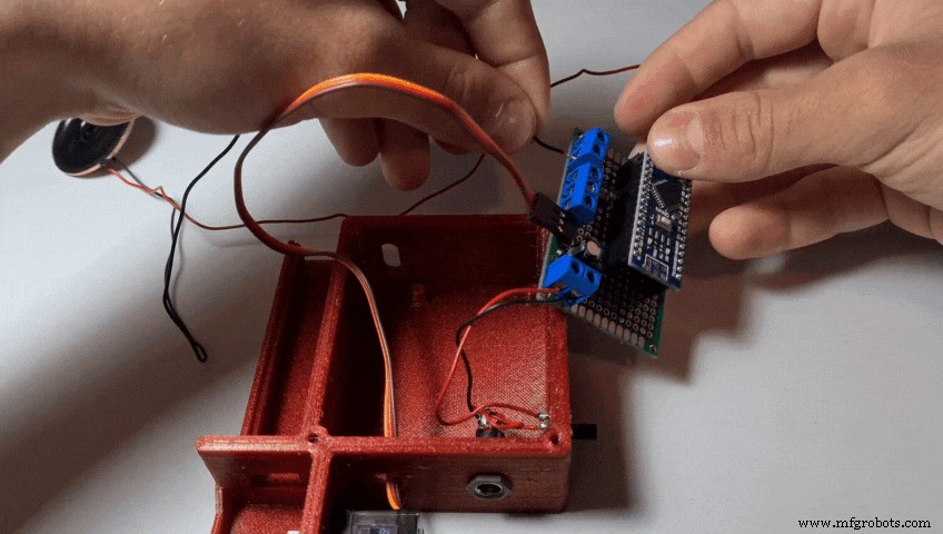
- 连接扬声器
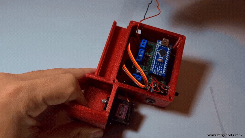
第 19 步:将 PCB 连接到底座
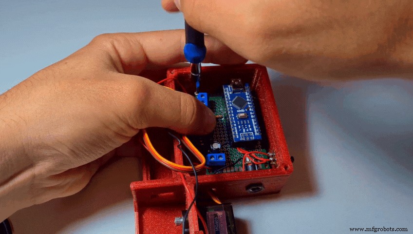
- 将 PCB 装入底座
- 用 2-4 个 M2 螺钉将其固定到位
第 20 步:切割和安装塑料板
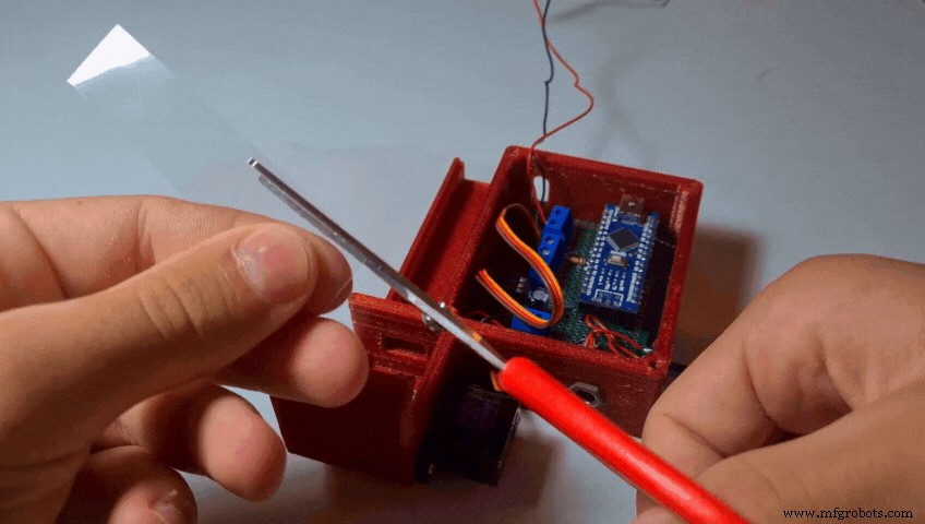
- 将透明塑料片切成约 75 毫米 x 17 毫米的矩形并修剪其边,直至其与底座紧密贴合。
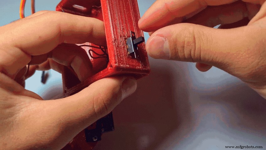
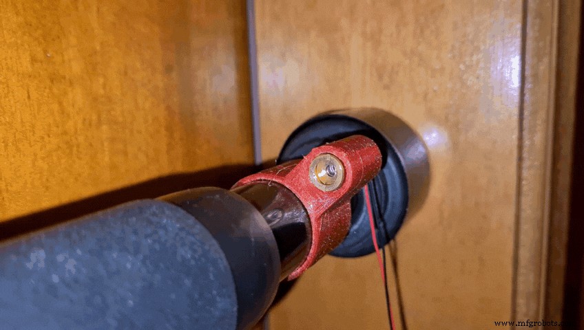
第 21 步:将激光器安装到杆上
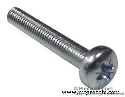
- 将 LaserClamp 连接到拉杆的一侧,并使用 M4 螺钉和螺母拧紧夹具
第 22 步:将 LDR 安装到 Bar
- 将 LdrClamp 连接到杆的另一侧,然后使用 M4 螺钉和螺母再次拧紧
步骤 23:对准激光和 LDR
- 通过将激光模块连接到 ~5V 来打开它 电源(Arduino 5V 引脚、3 节 AA 电池、1S Lipo、18650 电池或任何您喜欢的电池)
- 旋转夹具直到激光束击中 LDR 中心
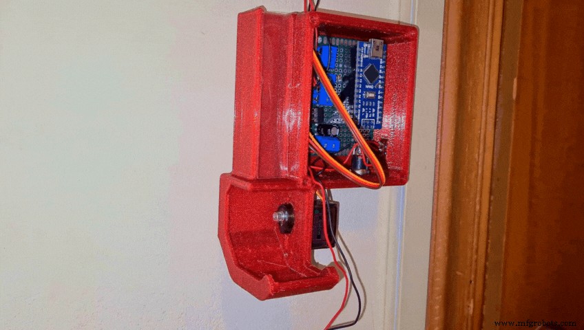
第 24 步:将外壳粘在墙上

- 使用热胶枪(可能是所有制造商最喜欢的工具),将底座粘在墙上。
步骤 25:将激光器和 LDR 连接到 PCB
- 将激光和 LDR 的电缆缠绕在门上
- 将两根红线连接到三重螺丝端子的中央部分
- 将 LDR 的黑线连接到上部
- 和激光的黑线连接到另一部分
(当然,所有这些连接都会根据您制作 PCB 的方式和方式而有所不同,而我的只能用作概念参考)
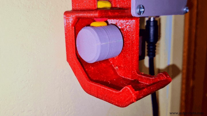
步骤 26:安装分配器
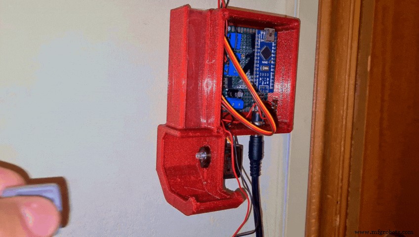
- 将电源连接到 DC 插孔并打开开关
当 Arduino 首次通电时,伺服会自动转到 0 度位置 并锁定到位。发生这种情况时,将 RotatorDispenser 连接到它。确保 Tic Tacs 的两个孔正确对齐 .
第 27 步:添加封面
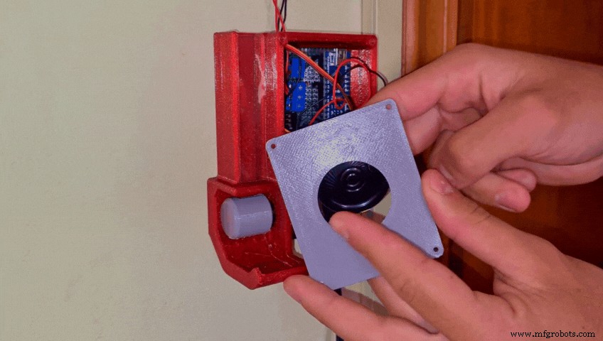
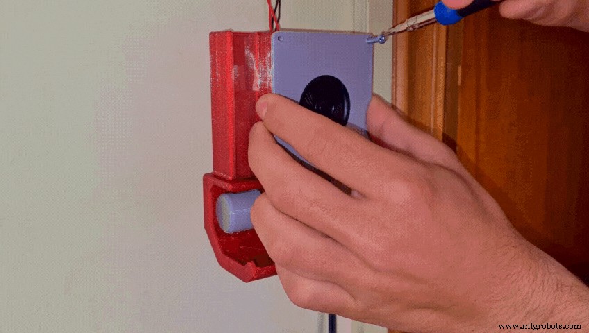
- 将扬声器装入盖子
- 使用 2 - 4 个 M3 螺钉将盖子拧到底座上
第 28 步:添加 Tic Tac!
最后添加一些 Tic Tacs ......
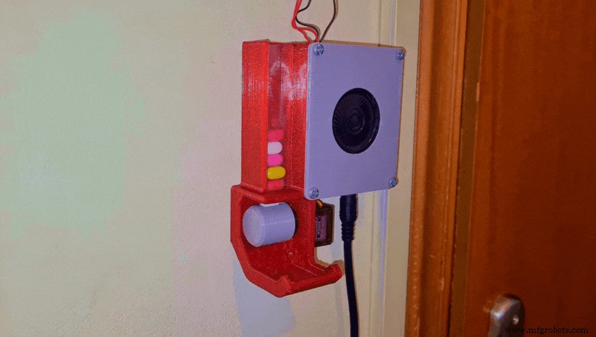
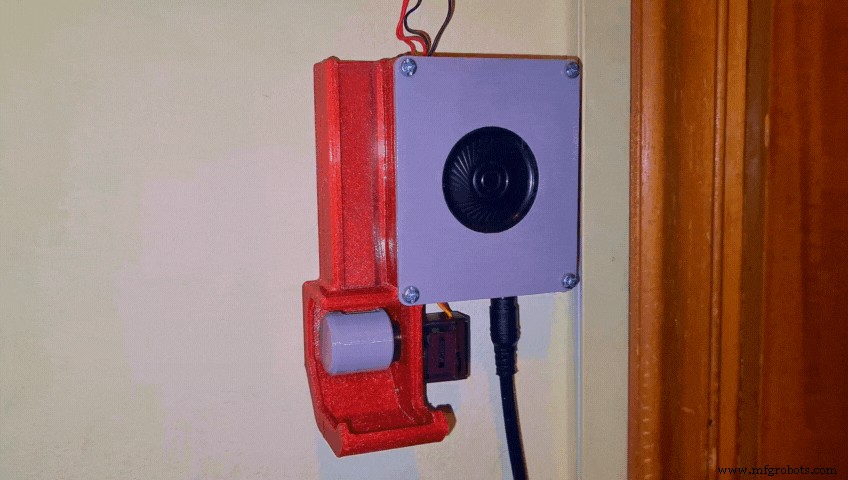
第 29 步:祝贺项目现已完成!
Smart Pull-Up Bar 终于完成了!!
我希望你和我一样喜欢这个教程!如果您有任何问题或建议,请告诉我!还可以考虑订阅我的 YouTube 频道 获取更多教程、酷构建并在整个旅程中为我提供支持。祝您有美好的一天!
代码
- SmartPullUpBar.ino
SmartPullUpBar.inoArduino
无预览(仅限下载)。
定制零件和外壳
物联网
https://www.thingiverse.com/thing:4809522thingiverse.com 上的 CAD 文件示意图
制造工艺