

WiDC:Wi-Fi 控制的 FPV 机器人
组件和用品
 |
| × | 1 | |||
 |
| × | 1 | |||
 |
| × | 1 | |||
| × | 1 | ||||
| × | 1 |
应用和在线服务
 |
| |||
 |
|
关于这个项目
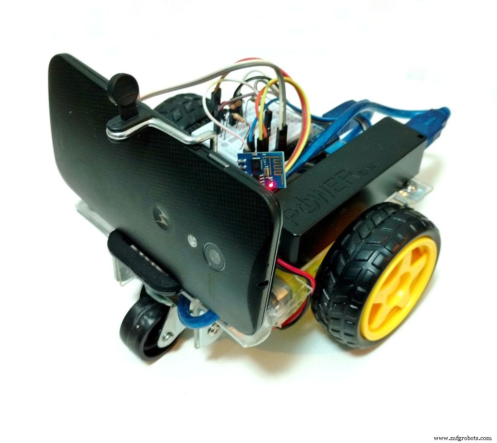

使用遥控机器人探索周围环境、到达人迹罕至的地方、监视、拍照、制作电影或播放视频怎么样?本教程将向您展示如何为所有这些目的制作一个不可消耗的东西!
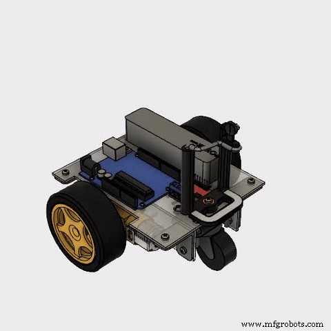
本教程是对我之前的教程(https://www.instructables.com/id/Wi-fi-Controlled-FPV-Rover-Robot-with-Arduino-ESP8/)的改进,其中我提出了一个更快的主页-做的机器人。它展示了如何使用两个直流电机、一个 Arduino Uno 和一个 ESP8266 Wi-Fi 模块,通过 Wi-Fi 网络设计远程控制的两轮机器人。
可以使用 HTML 设计的界面从普通的互联网浏览器控制机器人。 Android 智能手机可能用于将视频和音频从机器人广播到控制界面。
在我之前的教程中,我展示了如何使用普通工具(不需要 3D 打印机、激光切割机或 CNC 路由器)为机器人项目设计和构建低成本框架。
人们可能会注意到这里使用的组件可能没有针对其目的进行优化。例如,可以使用 NodeMCU 代替 Arduino + ESP8266 组合。带有摄像头的 Rapsberry Pi 将取代智能手机并控制电机。甚至可以将 Android 智能手机用作机器人的“大脑”。原来如此……
本教程源自我参与的另一个项目:Joy Robot(https://hackaday.io/project/12873-rob-da-alegria-joy-robot 或 https://www.hackster.io/igorF2/ robo-da-alegria-joy-robot-85e178),为了简单起见,这里使用了相同的硬件。选择 Arduino Uno 是因为它对每个人来说都非常易于使用和使用,我们想为它设计一个简单的盾牌。在我们原来的项目中,还控制一些舵机和 LED 矩阵,并与 ESP 接口。智能手机实际上被平板电脑取代,平板电脑也可以运行其他应用程序。您可能会在以下链接中找到与该机器人相关的其他教程:
使用 Arduino Uno 控制 LED 矩阵阵列:
https://www.instructables.com/id/Controlling-a-LED-Matrix-Array-With-Arduino-Uno/
Wi-Fi 浏览器控制的伺服电机:
https://www.instructables.com/id/Wi-Servo-Wi-fi-Browser-Controlled-Servomotors-with/
本指南可能会进行调整,并更改其形状或控制界面以满足您的需要。
在另一个教程中,我介绍了一种使用 Blynk 应用程序从智能手机控制机器人的方法!看看:
https://www.hackster.io/igorF2/wi-fi-controlled-robot-using-wemos-d1-esp8266-and-blynk-464198
第 1 步:工具


以下工具用于构建该原型:
工具:
- 手锯(用于切割亚克力板)
- 螺丝刀(用于放置螺栓和螺母)
- 标尺(用于测量模型尺寸)
- 美工刀(用于切割结构和打孔)
- 钻孔机(用于在亚克力上钻孔以安装螺丝)
- 砂纸(平滑粗糙边缘)
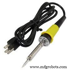
- 烙铁(用于焊接电机端子)
- 一台电脑(用于编译和上传 Arduino 代码)
这些工具用于机器人机械结构的生产、机器人的组装和电子元件的连接。如果您选择购买结构而不是建造自己的结构,则不需要某些工具。
您甚至可以使用其他设备(例如 3D 打印机或激光切割机),具体取决于您的创客空间可用的工具。
第二步:机械结构和材料


机械结构采用以下材料:
机械材料:
- 2mm亚克力板
- 带轮的直流齿轮电机 (x2)
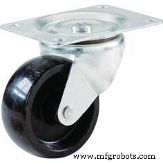
- 30mm 脚轮 (x1)
- M2 x 10mm 螺丝 (x5)
- M2 x 1,5mm 螺母 (x5)
- M3 x 10mm 螺丝 (x9)
- M3 x 10mm 螺丝 (x9)
- M3 x 40 毫米螺丝 (x4)
- M3 x 1,5mm 螺母 (x12)
- 5/32" x 1" 螺丝 (x4)
- 5/32" 螺母 (x12)
- 通用手机支架
- 钢制角钢“L”形支架(30 x 30 毫米)(x4)
第三步:电子元件


本机器人使用的以下电子元件:
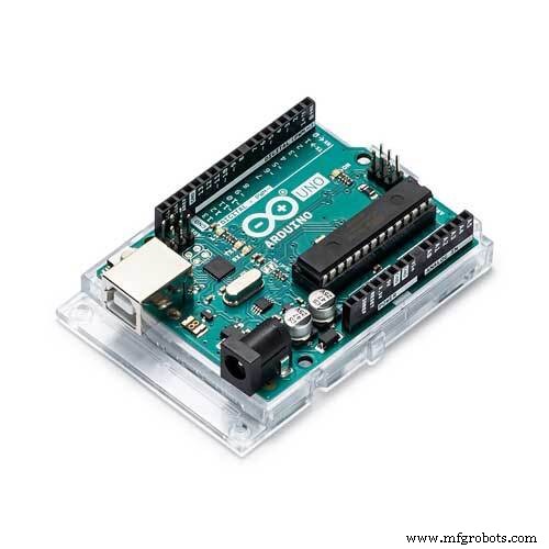
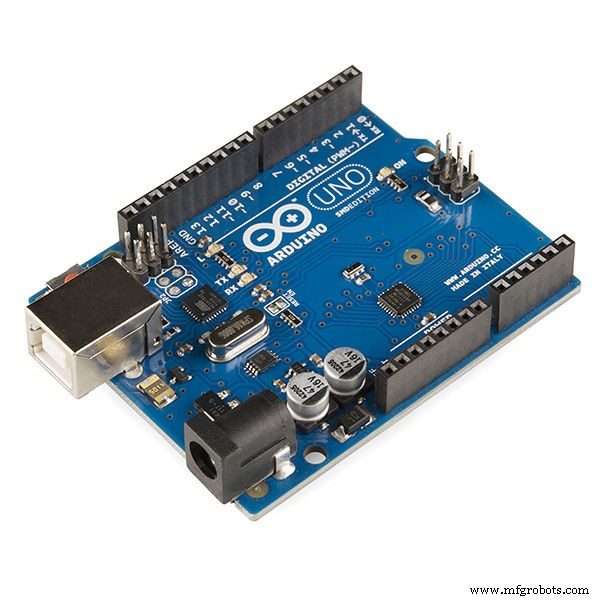
• Arduino Uno(购买/购买)
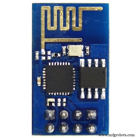
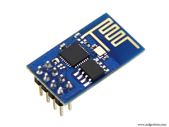
• ESP8266(购买)
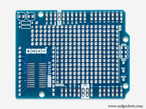
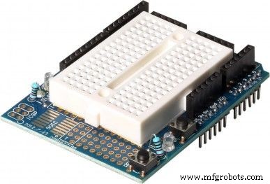
• Protoshield(用于更紧凑的版本)或普通面包板(购买)
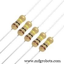
• 1 kohm 电阻 (x2)
• 10 kohm 电阻 (x1)
• 带轮直流减速电机(x2)(购买)
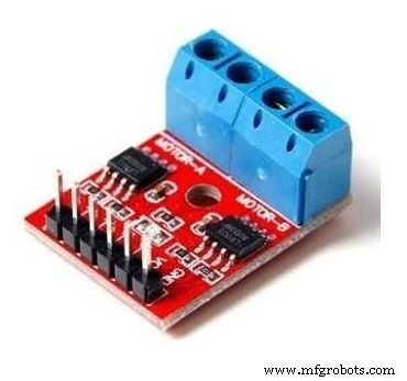
• H 桥模块(购买)
• 一些跳线
• 5V USB 移动电源
您可以在您最喜欢的电子商务商店轻松地在线找到所有组件。
正如在本教程的介绍中强调的那样,组件的选择源自我设计的其他项目,并且可能使用不同的微控制器进行优化,例如。
第 4 步:设计结构
首先我必须设计我的机器人的机械结构。如果您不想构建自己的自定义结构(网上有很多机器人套件),您也可以在线购买完整的结构。在这种情况下,您可能会跳到第 6 步。在本教程中,我们设计了一个低成本的亚克力框架,用于连接电机和其他组件。本教程中介绍的结构是使用 Fusion 360 CAD 软件进行 3D 设计并使用普通工具构建的(不需要 3D 打印机、激光切割机或 CNC 路由器)。您可以使用下面描述的相同原则来设计适合您需求的自定义结构。
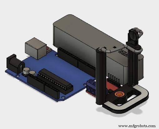
首先,我必须制作主要组件的 3D 模型,以决定结构的排列。其中一些是从 GrabCAD 社区库 (https://grabcad.com/library ):
- Arduino Uno (https://grabcad.com/library/arduino-uno-13)
- 齿轮马达 (https://grabcad.com/library/bomotor-1)
- H 桥 (https://grabcad.com/library/motor-driver-l9110-1)
- 移动电源 (https://grabcad.com/library/power-bank-7)
- 通用手机支架 (https://grabcad.com/library/universal-phone-holder-for-the-gopro-accessories-1)
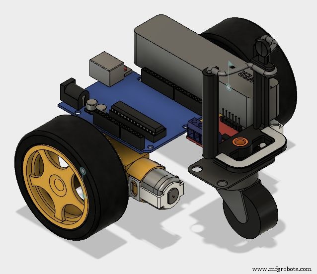
电子元件排列在一个平面上,这样我就可以计算出我的机器人需要的占地面积。之后,我不得不选择电机和车轮的位置,以创建一个稳定的结构。
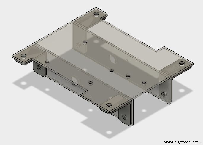
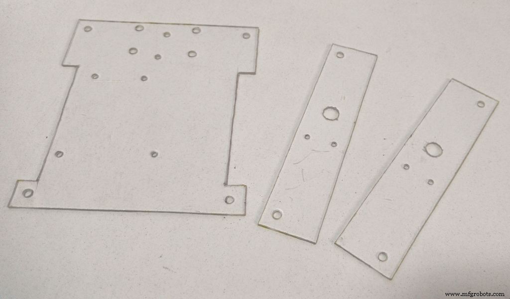
在此基础上,设计了主体结构,由三块板(一块底板和两块侧板)通过支架连接而成。
base.pdf 基础.svg
第 5 步:构建和组装结构

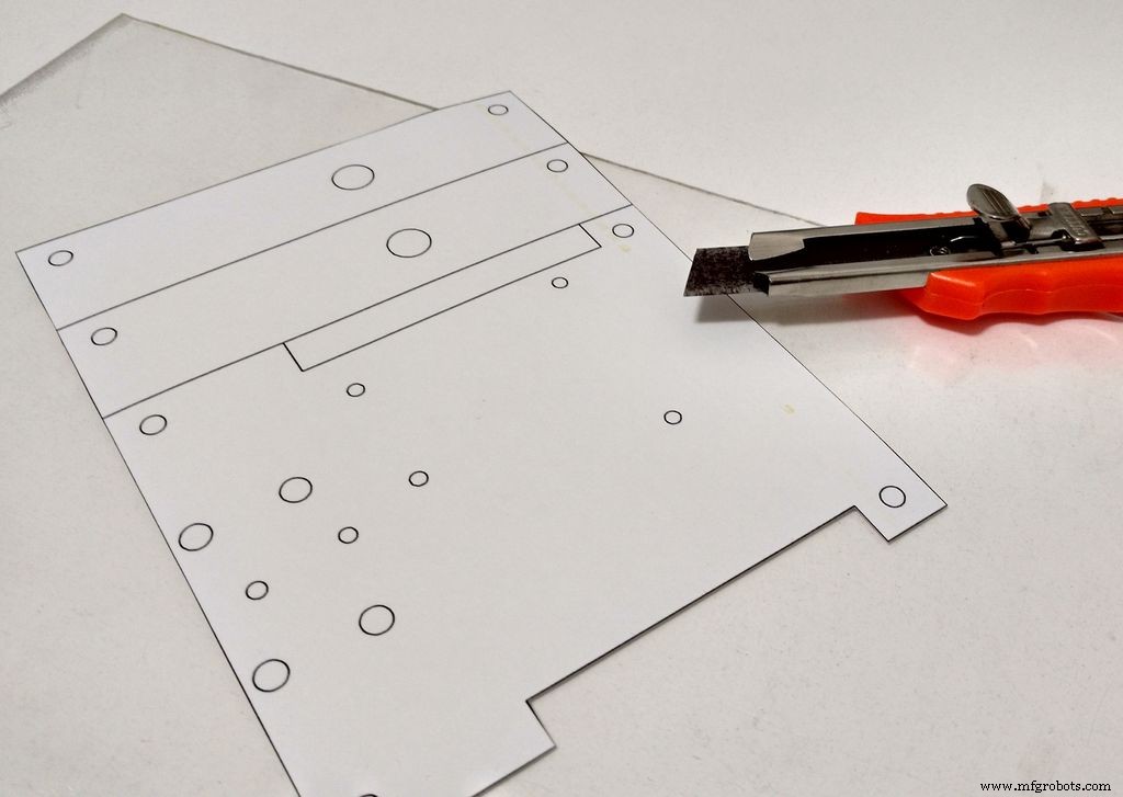
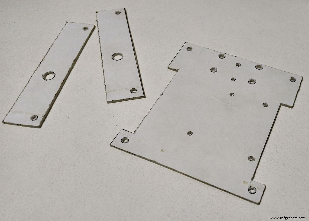
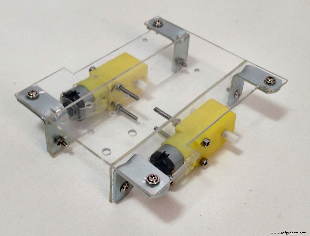

底座结构的搭建分为以下几个步骤:1.根据二维图中的尺寸切割亚克力底座: 这可以使用激光切割机(如果您可以使用)或像我这样使用普通工具来完成。
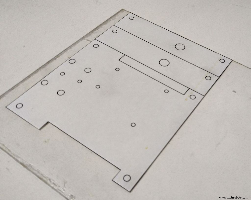
首先,您需要将模型的尺寸转移到亚克力板上。使用普通打印机在不干胶纸上打印您的 2D 绘图,然后将纸张剪成合适的尺寸并将该面膜贴在亚克力表面上。直线。您不需要一直切割整个片材,只需对其进行评分以创建一些轨道,然后将在该轨道上切割该片材。将亚克力放在平坦的表面上,用一些夹子将其固定到位并施加一些压力,直到板材断裂成两半。重复此过程,直到完成所有切割。之后,您可以使用砂纸打磨粗糙的边缘。您也可以使用手锯切割亚克力。2。在二维图中所示位置钻孔: 用钻孔机在二维图(面罩中所示)所示位置钻孔。亚克力相对容易钻孔。因此,如果您不处理钻孔机,则可以使用锋利的工具(如美工刀)手动钻孔。您也可以使用它来扩大小孔以适应螺钉尺寸。取下面具,你的基地就准备好了。
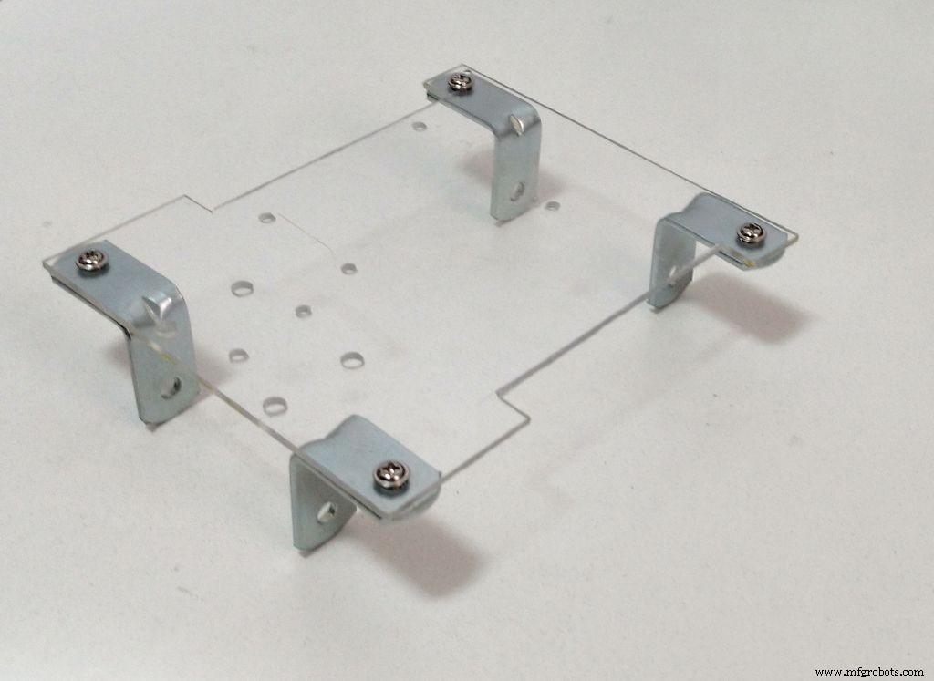
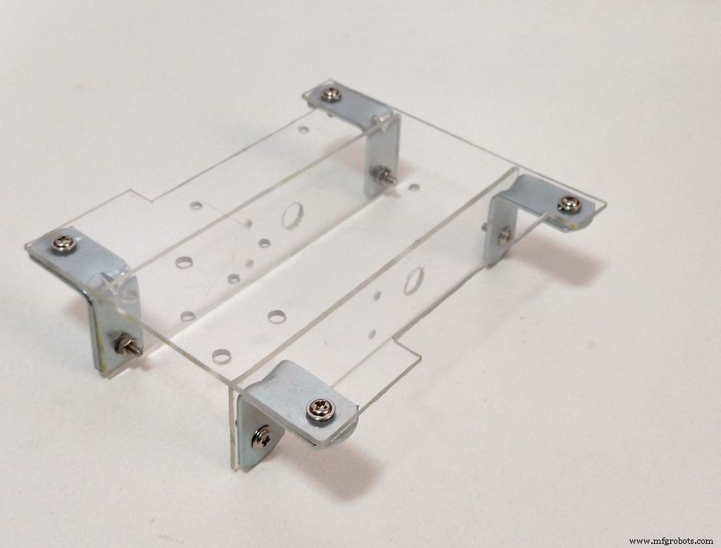
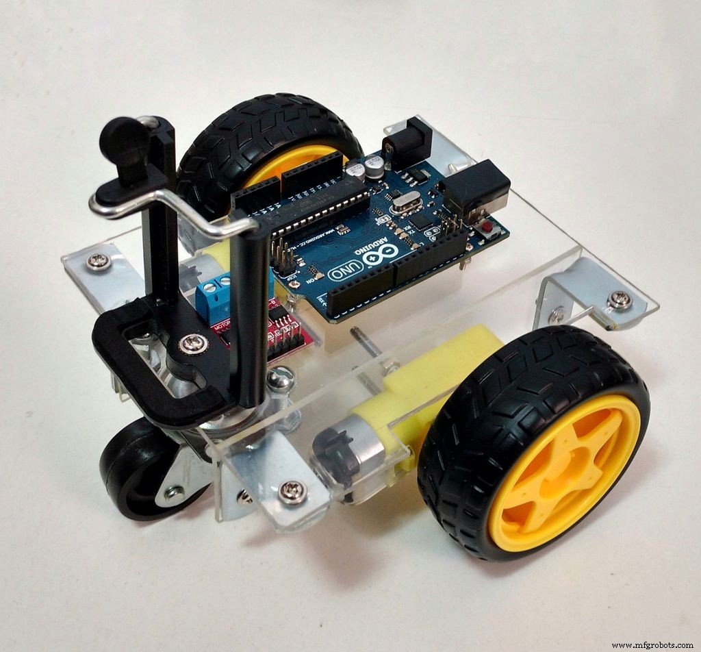
3.根据 3D 图纸用螺钉和螺母安装组件: 根据视频用螺钉和螺母安装组件,您的结构就准备好了。 M3 螺钉用于安装支架和直流电机。 M2螺丝用于安装电子元件,而5/32"螺丝用于安装前轮和智能手机夹。现在休息一下,开始下一步组装电路...... 基础.pdf
第 6 步:组装电子设备
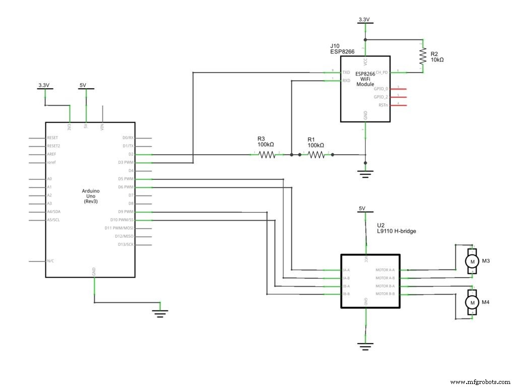
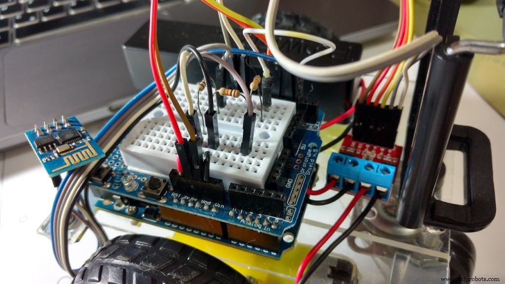
这里提出的电路使用Arduino Uno作为主控制器,与ESP8266接口进行Wi-Fi通信。 Arduino使用H桥驱动电路控制直流电机,最多可以控制两个电机,旋转他们在两个方向上独立。
移动电源用于为电子设备供电,直接连接到 Arduino 的 USB 端口。这是一种为 Arduino 供电的简单方法:易于充电,易于更换,并提供安全的 5V 电压。
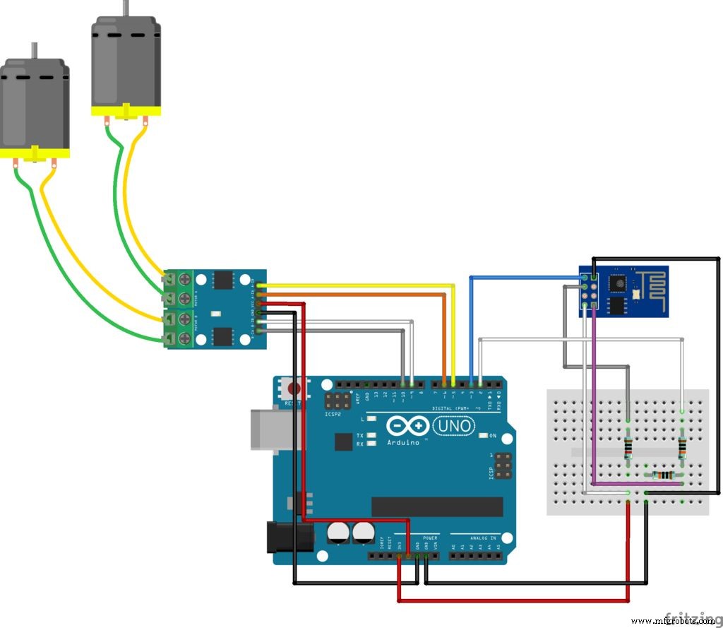
根据原理图连接所有组件。您需要一些跳线来连接 ESP8266 模块,该模块不适合原型板、h 桥和直流电机。您可以使用 protoshield(用于更紧凑的电路)、普通面包板,或设计您自己的 Arduino 扩展板。
您会注意到 ESP8266-1 不适合面包板。它将使用一些跳线连接,但不会连接到结构上。
将 USB 电缆插入 Arduino 的开发板并继续下一步。
wiDC_Esquem_C3_A1tico.pdf wiDC.fzz wiDC_bb.pdf
第 7 步:Arduino 代码
安装最新的 Arduino IDE。与ESP-8266模块通信或控制电机不需要库。请检查您的ESP8266的波特率并在代码中正确设置。下载Arduino代码(WiDC.ino)并将XXXXXX替换为您的wifi路由器SSID和YYYYY 通过路由器密码。将 Arduino 板连接到您的计算机 USB 端口并上传代码。
将 USB 电缆插入 Arduino 的开发板并继续下一步。
//include libraries#include SoftwareSerial esp8266(3, 2); //RX pin =3, TX pin =2//定义变量#define DEBUG true //显示ESP8266和Arduino串口状态=5的消息; //定义机器人的初始状态(5 =待机)//定义电机引脚const int motor1Pin1 =5;const int motor1Pin2 =6;const int motor2Pin1 =9;const int motor2Pin2 =10;//定义电机速度int motorSpeed =150; //电机速度(PWM)//*****//SETUP//*****void setup(){ //设置引脚模式 pinMode(motor1Pin1, OUTPUT); pinMode(motor1Pin2, OUTPUT); pinMode(motor2Pin1,输出); pinMode(motor2Pin2,输出); //开始通信 Serial.begin(9600); esp8266.begin(9600); sendData("AT+RST\r\n", 2000, DEBUG); //重置模块sendData("AT+CWMODE=1\r\n", 1000, DEBUG); //设置电台模式 sendData("AT+CWJAP=\"XXXXX\",\"YYYYY\"\r\n", 2000, DEBUG); //连接Wi-Fi网络(用你的Wi-Fi路由器SSID替换XXXXX,用密码delay(5000)替换YYYYY;//等待连接sendData("AT+CIFSR\r\n", 1000, DEBUG); / /show IP 地址 sendData("AT+CIPMUX=1\r\n", 1000, DEBUG); //允许多个连接 sendData("AT+CIPSERVER=1,80\r\n", 1000, DEBUG); / / 在 80 端口启动 web 服务器}//*********//MAIN LOOP//*********void loop(){ if (esp8266.available()) //验证传入数据 { if (esp8266.find("+IPD,")) //如果有消息 { String msg; esp8266.find("?"); //查找消息 msg =esp8266.readStringUntil(' ' ); //读取整个消息 String command =msg.substring(0, 3); //前 3 个字符 =command Serial.println(command); //向前移动 if(command =="cm1") { state =1; } //向后移动 if(command =="cm2") { state =2; } //右转 if(command =="cm3") { state =3; } //左转 if(command ==" cm4") { state =4; } // 什么都不做 if(command =="cm5") { state =5; } } } //STATE 1:向前移动 if (state ==1) { analogWrite(m otor1Pin1, motorSpeed);数字写入(motor1Pin2,低);模拟写入(motor2Pin1,motorSpeed);数字写入(motor2Pin2,低); } //STATE 2:向后移动 if (state ==2) { digitalWrite(motor1Pin1, LOW);模拟写入(motor1Pin2,motorSpeed);数字写入(motor2Pin1,低);模拟写入(motor2Pin2,motorSpeed); } //STATE 3:向右移动 if (state ==3) { analogWrite(motor1Pin1, motorSpeed);数字写入(motor1Pin2,低);数字写入(motor2Pin1,低);模拟写入(motor2Pin2,motorSpeed); } //STATE 4:向左移动 if (state ==4) { digitalWrite(motor1Pin1, LOW);模拟写入(motor1Pin2,motorSpeed);模拟写入(motor2Pin1,motorSpeed);数字写入(motor2Pin2,低); } //STATE 5:if (state ==5) { digitalWrite(motor1Pin1, LOW);数字写入(motor1Pin2,低);数字写入(motor2Pin1,低);数字写入(motor2Pin2,低); }//*******************//辅助函数//*******************String sendData (字符串命令,const int 超时,布尔调试){ String response =""; esp8266.print(命令); long int time =毫秒(); while ( (time + timeout)> millis()) { while (esp8266.available()) { char c =esp8266.read();响应 +=c; } } 如果(调试){ Serial.print(响应); } 返回响应;} 代码解释:
该代码使用一个串口用于Arduino和ESP8266之间的通信,另一个用于Arduino和计算机之间的通信。一旦 Arduino Uno 只有一个串行端口,SoftwareSeial 库就被用来创建第二个端口,使用数字引脚 2 和 3。
//include libraries#include SoftwareSerial esp8266(3, 2); //RX pin =3, TX pin =2 在设置期间,必须启动两个串行通信,并定义它们的波特率(一个在 Arduino 和您的串行监视器之间,另一个与 ESP8266 速度相匹配)。请注意,我的 ESP8266 设置为 9600 kbps。默认情况下,这些模块中的大多数都以 115200kbps 的速度运行,但 SoftwareSerial 库无法以这种速度工作,您必须更改其波特率。对我来说 9600 kbps 工作正常。
在这个项目中,我没有使用特定的库来与 Wi-Fi 模块进行通信。相反,只使用了以下普通的 AT 命令(ESP8266 默认固件上定义的一组指令):
- AT+RST:重置ESP8266模块
- AT+CWMODE:设置模块为站模式或接入点
- AT+CWJAP:连接由其 SSID 和密码指定的 Wi-Fi 网络
- AT+CIPMUX:设置模块为多连接或单连接
- AT+CIPSERVER:在给定端口上启动网络服务器//开始通信
Serial.begin(9600); esp8266.begin(9600); sendData("AT+RST\r\n", 2000, DEBUG); //重置模块sendData("AT+CWMODE=1\r\n", 1000, DEBUG); //设置电台模式 sendData("AT+CWJAP=\"XXXXX\",\"YYYYY\"\r\n", 2000, DEBUG); //连接Wi-Fi网络(用你的Wi-Fi路由器SSID替换XXXXX,用密码delay(5000)替换YYYYY;//等待连接sendData("AT+CIFSR\r\n", 1000, DEBUG); / /show IP 地址 sendData("AT+CIPMUX=1\r\n", 1000, DEBUG); //允许多个连接 sendData("AT+CIPSERVER=1,80\r\n", 1000, DEBUG); / / 在端口 80 上启动 Web 服务器 一个辅助函数(sendData)用于发送数据(从Arduino到ESP8266),读取并在串口监视器上显示响应。
String sendData(String command, const int timeout, boolean debug){ String response =""; esp8266.print(命令); long int time =毫秒(); while ( (time + timeout)> millis()) { while (esp8266.available()) { char c =esp8266.read();响应 +=c; } } 如果(调试){ Serial.print(响应); }返回响应;} 使用上面的代码使 Arduino 重置模块,加入网络,等待连接,然后显示其 IP 地址并启动网络服务器。之后,主循环将开始,微控制器将等待命令。
void loop(){ if (esp8266.available()) //验证传入的数据 { if (esp8266.find("+IPD,")) //如果有消息 { String msg; esp8266.find("?"); //寻找消息 msg =esp8266.readStringUntil(' '); //读取整个消息 String command =msg.substring(0, 3); //前 3 个字符 =命令 Serial.println(command); //向前移动 if(command =="cm1") { state =1; } //向后移动 if(command =="cm2") { state =2; } //右转 if(command =="cm3") { state =3; } //左转 if(command =="cm4") { state =4; } //什么都不做 if(command =="cm5") { state =5; } } } 定义了五个可能的命令(cm1 到 cm5)。每当 Arduino 收到这些命令之一时,它就会进入五种可能的状态之一(向前移动、向后移动、向右移动、向左移动和待机),并继续保持该状态,直到收到不同的命令。
每个状态定义了电机引脚的信号。当我想将一个引脚设置为 0V 时,我使用了 digitalWrite(pin, LOW),当我想打开一个引脚时,我使用了analogWrite(pin, motoSpeed)。使用analogWrite可以让我改变电机的速度,让机器人移动得更慢。
//STATE 1:move forward if (state ==1) { analogWrite(motor1Pin1, motorSpeed);数字写入(motor1Pin2,低);模拟写入(motor2Pin1,motorSpeed);数字写入(motor2Pin2,低); } //STATE 2:向后移动 if (state ==2) { digitalWrite(motor1Pin1, LOW);模拟写入(motor1Pin2,motorSpeed);数字写入(motor2Pin1,低);模拟写入(motor2Pin2,motorSpeed); } //STATE 3:向右移动 if (state ==3) { analogWrite(motor1Pin1, motorSpeed);数字写入(motor1Pin2,低);数字写入(motor2Pin1,低);模拟写入(motor2Pin2,motorSpeed); } //STATE 4:向左移动 if (state ==4) { digitalWrite(motor1Pin1, LOW);模拟写入(motor1Pin2,motorSpeed);模拟写入(motor2Pin1,motorSpeed);数字写入(motor2Pin2,低); } //STATE 5:if (state ==5) { digitalWrite(motor1Pin1, LOW);数字写入(motor1Pin2,低);数字写入(motor2Pin1,低);数字写入(motor2Pin2,低); } 请注意,电机在 3 到 6V 之间工作。使用 5V 电源后,您可以在 3 到 5V 之间调制电机的平均电压(使用 PWM),从而改变其速度。它不会让你精细控制机器人的速度
WiDC.ino
步骤 8:基于 Web 的控制界面
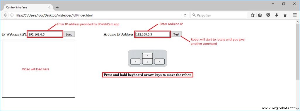
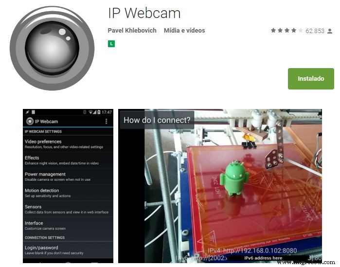
为控制机器人设计了一个html界面。下载interface.rar并将所有文件解压到一个给定的文件夹。然后在 Firefox 上打开它。在该界面中使用文本框形式输入 ESP 模块和视频/音频服务器(来自 Android IP 网络摄像头应用程序)的 IP 地址。有一个测试但是,它将使机器人旋转,直到收到另一个命令。键盘方向键用于机器人向前或向后移动,向左或向右旋转。Android智能手机用于将机器人的视频和音频广播到控制界面。您可以在 Google Play 商店 (https://play.google.com/store/apps/details?id=com.pas.webcam) 上找到该应用。安装它并进行下一步。
HTML 代码解释:
html界面分为两部分:一是音视频(来自Android IP网络摄像头服务器),一是命令。
音视频师有一个表单,带有一个文本框一个按钮。这用作指定网络摄像头服务器 IP 地址并加载它的输入。它自带一个标准IP地址(192.168.0.5),但使用时可以输入不同的IP。视频和音频加载在文本框下方的对象中。
另一个部门有另一种形式的文本框,以便用户可以告知其ESP8266的IP地址。

按住键盘方向键移动机器人
JavaScript 用于处理接口并向 Arduino 发送数据。这些脚本被编码在不同的文件中,并添加到 html 标题中。
控件界面 Javascript 解释:
一个函数(readUrlAV)用于从html表单中读取IP地址并将它们加载到“视频”和“音频”对象中。
function readUrlAV (form) { TextVar =form.inputbox.value; VideoVar ="http://"+TextVar+":8080/video"; AudioVar ="http://"+TextVar+":8080/audio.opus"; document.getElementById("video").setAttribute('data', VideoVar); document.getElementById("audio").setAttribute('data', AudioVar);} 该脚本定期读取键盘,等待用户按下任意键。如果用户按下任何箭头键(左 ='37',向上 ='38',右 ='39' 或 '向下' =40),它会为给定的 IP 发送一个命令(“cm1”到“cm4”)地址。请注意,有一个闩锁功能,可以避免一遍又一遍地重复相同的命令。数据只有在按键被按下时才会传输。
var latch =false;document.onkeydown =checkKeyDown;function checkKeyDown(e) { e =e ||窗口事件; if (e.keyCode =='38') { // 向上箭头 if (latch ==false) { TextVar =myform2.inputbox.value; ArduinoVar ="http://" + TextVar + ":80"; $.get(ArduinoVar, { "cm1":1000 }); {连接:关闭};闩锁=真; } } else if (e.keyCode =='40') { // 向下箭头 if (latch ==false) { TextVar =myform2.inputbox.value; ArduinoVar ="http://" + TextVar + ":80"; $.get(ArduinoVar, { "cm2":1000 }); {连接:关闭};闩锁=真; } } else if (e.keyCode =='37') { // 左箭头 if (latch ==false) { TextVar =myform2.inputbox.value; ArduinoVar ="http://" + TextVar + ":80"; $.get(ArduinoVar, { "cm3":1000 }); {连接:关闭};闩锁=真; } } else if (e.keyCode =='39') { // 向右箭头 if (latch ==false) { TextVar =myform2.inputbox.value; ArduinoVar ="http://" + TextVar + ":80"; $.get( ArduinoVar, { "cm4":1000 }); {连接:关闭};闩锁=真; } }} 当任何方向键被释放时,doNothing 函数被执行,它发送命令“cm5”(停止电机),并重置锁存器,允许接口发送不同的命令。
document.onkeyup =checkKeyUp;function checkKeyUp(e) { e =e ||窗口事件; if ((e.keyCode =='38')||(e.keyCode =='40')||(e.keyCode =='37')||(e.keyCode =='39')) { setTimeout(doNothing, 200); }}function doNothing(){ TextVar =myform2.inputbox.value; ArduinoVar ="http://" + TextVar + ":80"; $.get( ArduinoVar, { "cm5":1000 }); {Connection:close}; latch =false;}
Step 9:Usage
When the Arduino is restarted, it will try to connect your wi-fi network automatically. Use the Serial Monitor to check if the connection was successfull, and to obtain which IP was assigned to your ESP-8266 by your router. Open the html file in an internet browser (Firefox) and inform this IP address in the textbox.You might also user other means to find out which IP address you router assigned to your device. Disconnect the the Arduino Uno from your computer and connect it to the power bank. Wait for it to connect again. Launch IP Webcam app in the smartphone attached to the robot. Type the video/audio IP on your control interface and connect to the server and you'll be ready to go. You might need to reduce the resolution of the video in the app to reduce the delay between during the transmission. Click and hold the arrow buttons of your keyboar to rotate the robot or move it forward/backward and have fun exploring your environment.
Notice that robot runs on open loop. This way, it's quite difficult to make it move straight forward. Small difference between the motors, aligment, etc. will cause cumulative deviations.
The robot start moving when it receives a given command ("cm1" to "cm4"), and keep that state until a different command is received ("cm1" to "cm5"). Sometimes the ESP8266 loses some messages, and that might cause some trouble. If, for instance, a "cm5" command is lost, the robot will keed moving even after any arrow key was released. I'm still dealing with this problem. Feel free to change the way the commands are interpreted to avoid this kind of problem.
代码
- Arduino 代码
- Interface
Arduino 代码Arduino
//include libraries#includeSoftwareSerial esp8266(3, 2); //RX pin =3, TX pin =2//definition of variables#define DEBUG true //show messages between ESP8266 and Arduino in serial portint state =5; //define initial state of the robot (5 =stand-by)//define motor pinsconst int motor1Pin1 =5;const int motor1Pin2 =6;const int motor2Pin1 =9;const int motor2Pin2 =10;//define motor speedint motorSpeed =150; //motor speed (PWM)//*****//SETUP//*****void setup(){ //set pin modes pinMode(motor1Pin1, OUTPUT); pinMode(motor1Pin2, OUTPUT); pinMode(motor2Pin1, OUTPUT); pinMode(motor2Pin2, OUTPUT); //start communication Serial.begin(9600); esp8266.begin(9600); sendData("AT+RST\r\n", 2000, DEBUG); //reset module sendData("AT+CWMODE=1\r\n", 1000, DEBUG); //set station mode sendData("AT+CWJAP=\"XXXXX\",\"YYYYY\"\r\n", 2000, DEBUG); //connect wi-fi network (replace XXXXX by your Wi-Fi router SSID and YYYYY by its password delay(5000); //wait for connection sendData("AT+CIFSR\r\n", 1000, DEBUG); //show IP address sendData("AT+CIPMUX=1\r\n", 1000, DEBUG); //allow multiple connections sendData("AT+CIPSERVER=1,80\r\n", 1000, DEBUG); // start web server on port 80}//*********//MAIN LOOP//*********void loop(){ if (esp8266.available()) //verify incoming data { if (esp8266.find("+IPD,")) //if there is a message { String msg; esp8266.find("?"); //look for the message msg =esp8266.readStringUntil(' '); //read whole message String command =msg.substring(0, 3); //first 3 characters =command Serial.println(command); //move forward if(command =="cm1") { state =1; } //move backward if(command =="cm2") { state =2; } //turn right if(command =="cm3") { state =3; } //turn left if(command =="cm4") { state =4; } //do nothing if(command =="cm5") { state =5; } } } //STATE 1:move forward if (state ==1) { analogWrite(motor1Pin1, motorSpeed); digitalWrite(motor1Pin2, LOW); analogWrite(motor2Pin1, motorSpeed); digitalWrite(motor2Pin2, LOW); } //STATE 2:move backward if (state ==2) { digitalWrite(motor1Pin1, LOW); analogWrite(motor1Pin2, motorSpeed); digitalWrite(motor2Pin1, LOW); analogWrite(motor2Pin2, motorSpeed); } //STATE 3:move right if (state ==3) { analogWrite(motor1Pin1, motorSpeed); digitalWrite(motor1Pin2, LOW); digitalWrite(motor2Pin1, LOW); analogWrite(motor2Pin2, motorSpeed); } //STATE 4:move left if (state ==4) { digitalWrite(motor1Pin1, LOW); analogWrite(motor1Pin2, motorSpeed); analogWrite(motor2Pin1, motorSpeed); digitalWrite(motor2Pin2, LOW); } //STATE 5:do nothing if (state ==5) { digitalWrite(motor1Pin1, LOW); digitalWrite(motor1Pin2, LOW); digitalWrite(motor2Pin1, LOW); digitalWrite(motor2Pin2, LOW); } }//*******************//Auxiliary functions//*******************String sendData(String command, const int timeout, boolean debug){ String response =""; esp8266.print(command); long int time =millis(); while ( (time + timeout)> millis()) { while (esp8266.available()) { char c =esp8266.read(); response +=c; } } if (debug) { Serial.print(response); } return response;}
InterfaceHTML
无预览(仅限下载)。
定制零件和外壳
base_7JLgOpcox6.svg示意图
制造工艺