

nRF24L01 – 工作原理、Arduino 接口、电路、代码
在本教程中,我们将学习如何进行无线通信 使用 nRF24L01 在两个 Arduino 板之间 收发模块。在使用 Arduino 时,nRF24L01 模块是非常受欢迎的无线通信选择。
我已经将这个模块用于许多 Arduino 项目,您可以在这里查看其中的一些:
您可以观看以下视频或阅读下面的书面教程。它包括我们需要了解的关于nRF24L01收发模块的所有信息,例如模块引脚排列、工作原理、接线和几个代码示例。
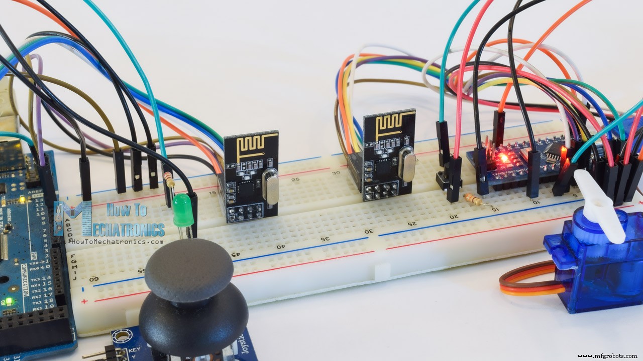
为了解释无线通信,我们将举两个例子,第一个是从一个 Arduino 向另一个 Arduino 发送简单的“Hello World”消息,在第二个例子中,我们将在 Arduino 板之间进行双向通信,其中使用第一个 Arduino 上的操纵杆我们将控制第二个 Arduino 上的伺服电机,反之亦然,使用第二个 Arduino 上的按钮我们将控制第一个 Arduino 上的 LED。
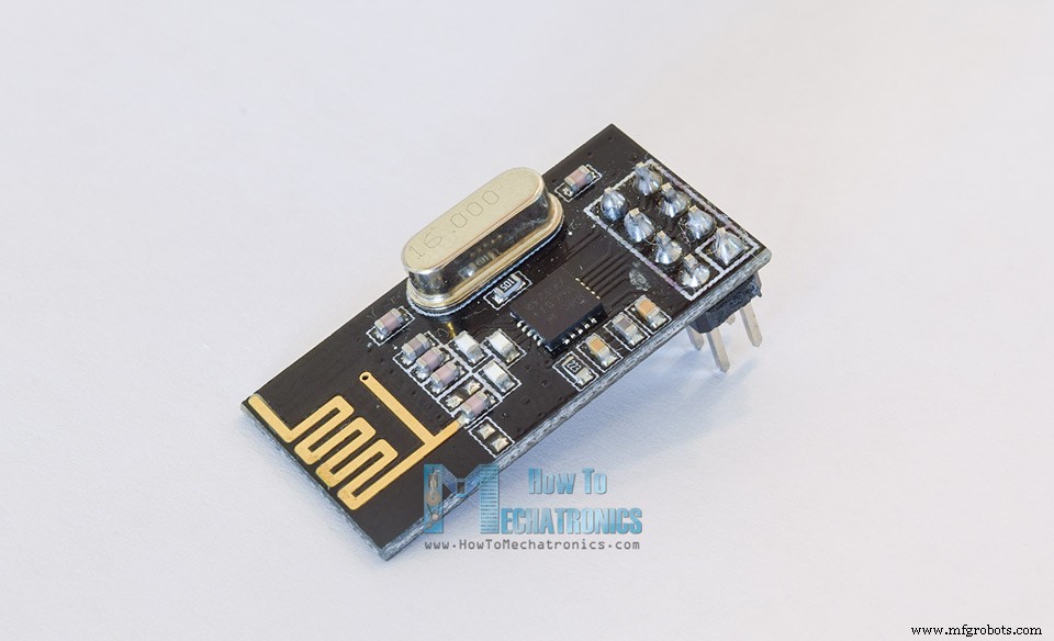
让我们仔细看看 NRF24L01 收发器模块。它使用 2.4 GHz 频段,可以在 250 kbps 到 2 Mbps 的波特率下运行。如果在空旷的地方使用,并且波特率较低,它的范围可以达到100米。
以下是完整的规格:
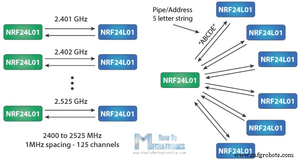
该模块可以使用 125 个不同的通道,从而可以在一个地方拥有一个由 125 个独立工作的调制解调器组成的网络。每个通道最多可以有 6 个地址,或者每个单元最多可以同时与 6 个其他单元通信。
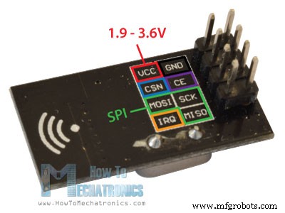
该模块在传输过程中的功耗仅为12mA左右,甚至低于单个LED。模块的工作电压为1.9~3.6V,好在其他管脚都可以承受5V逻辑,所以不用任何逻辑电平转换器就可以轻松连接到Arduino。
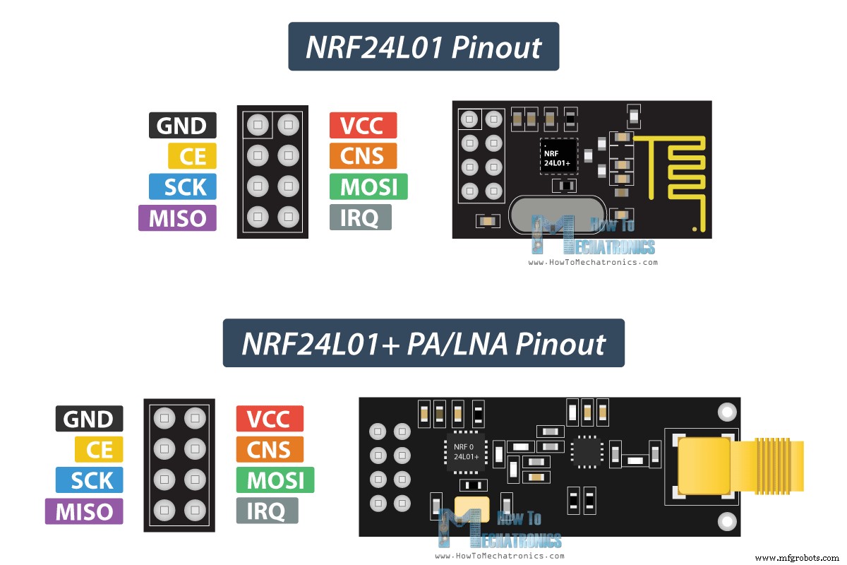
其中三个引脚用于 SPI 通信,它们需要连接到 Arduino 的 SPI 引脚,但请注意,每个 Arduino 板都有不同的 SPI 引脚。 CSN 和 CE 引脚可以连接到 Arduino 板的任何数字引脚,它们用于将模块设置为待机或活动模式,以及在传输模式或命令模式之间切换。最后一个管脚是中断管脚,不必使用。
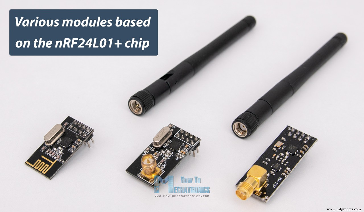
NRF24L01 模块有多种变体。最受欢迎的是带有板载天线的。这使得模块更紧凑,但另一方面,将传输范围降低到大约 100 米的距离。
第二种变体,它没有板载天线,而是有一个 SMA 连接器,我们可以连接一个鸭形天线以获得更好的传输范围。
这里显示的第三个变体,除了鸭子天线外,它还有一个RFX2401C芯片,其中包括PA (功率放大器)和 LNA (低噪声放大器)。这会放大 NRF24L01 信号,并在开放空间中实现更远的传输范围,最远可达 1000 米。
下面详细介绍 NRF24L01 引脚以及 NRF24L01+ PA/LNA 模块。
NRF24L01 和 NRF24L01+ PA/LNA 两个模块具有相同的引脚排列,因此我们可以将它们以相同的方式连接到我们的电路中。
以下是我们需要将 NRF24L01 模块连接到 Arduino 板的方法。
正如我已经提到的,每个 Arduino 板都有不同的 SPI 引脚,因此在将模块连接到 Arduino 板时请记住这一点。
您可以从以下链接获取本 Arduino 教程所需的组件:
一旦我们将 NRF24L01 模块连接到 Arduino 板,我们就可以为发射器和接收器制作代码了。
首先,我们需要下载并安装 RF24 库,这使得编程变得不那么困难。我们也可以直接从 Arduino IDE Library Manager 安装这个库。只需搜索“rf24”,然后通过“TMRh20, Avamander”找到并安装它。
这是无线通信的两个代码,下面是它们的描述。
所以我们需要包含基本的 SPI 和新安装的 RF24 库并创建一个 RF24 对象。这里的两个参数是 CSN 和 CE 引脚。
接下来我们需要创建一个字节数组来表示地址,或者两个模块将通过它进行通信的所谓管道。
我们可以将此地址的值更改为任何 5 个字母的字符串,这样就可以选择我们将与哪个接收器通信,因此在我们的例子中,接收器和发送器的地址将相同。
在设置部分,我们需要初始化无线电对象并使用 radio.openWritingPipe() 函数设置我们将发送数据的接收器的地址,即我们之前设置的 5 个字母的字符串。
另一方面,在接收端,我们使用 radio.setReadingPipe() 函数设置相同的地址,这样我们就可以在两个模块之间进行通信。
然后使用 radio.setPALevel() 函数我们设置功率放大器级别,在我们的例子中,我将它设置为最小,因为我的模块彼此非常接近。
请注意,如果使用更高的电平,建议在模块的 GND 和 3.3V 之间使用旁路电容,以便它们在工作时具有更稳定的电压。
接下来我们有radio.stopListening()函数将模块设置为发射器,另一方面,我们有radio.startListening()函数将模块设置为接收器。
在循环部分,在发送器处,我们创建了一个字符数组,我们将消息“Hello World”分配给这些字符。使用 radio.write() 函数,我们将把消息发送给接收者。这里的第一个参数是我们要发送的变量。
通过在变量名之前使用“&”,我们实际上设置了存储我们想要发送的数据的变量的指示,并使用第二个参数设置了我们想要从该变量中获取的字节数。在这种情况下,sizeof() 函数获取字符串“text”的所有字节。在程序结束时我们会添加 1 秒的延迟。
使用 radio.write() 函数,我们一次最多可以发送 32 个字节。
另一方面,在接收端,在使用 radio.available() 函数的循环部分中,我们检查是否有要接收的数据。如果是这样,首先我们创建一个包含 32 个元素的数组,称为“文本”,我们将在其中保存传入的数据。
使用 radion.read() 函数,我们读取数据并将其存储到“text”变量中。最后,我们只是在串行监视器上打印文本。因此,一旦我们上传了这两个程序,我们就可以在接收器上运行串行监视器,我们会注意到每秒都会打印出一条消息“Hello World”。
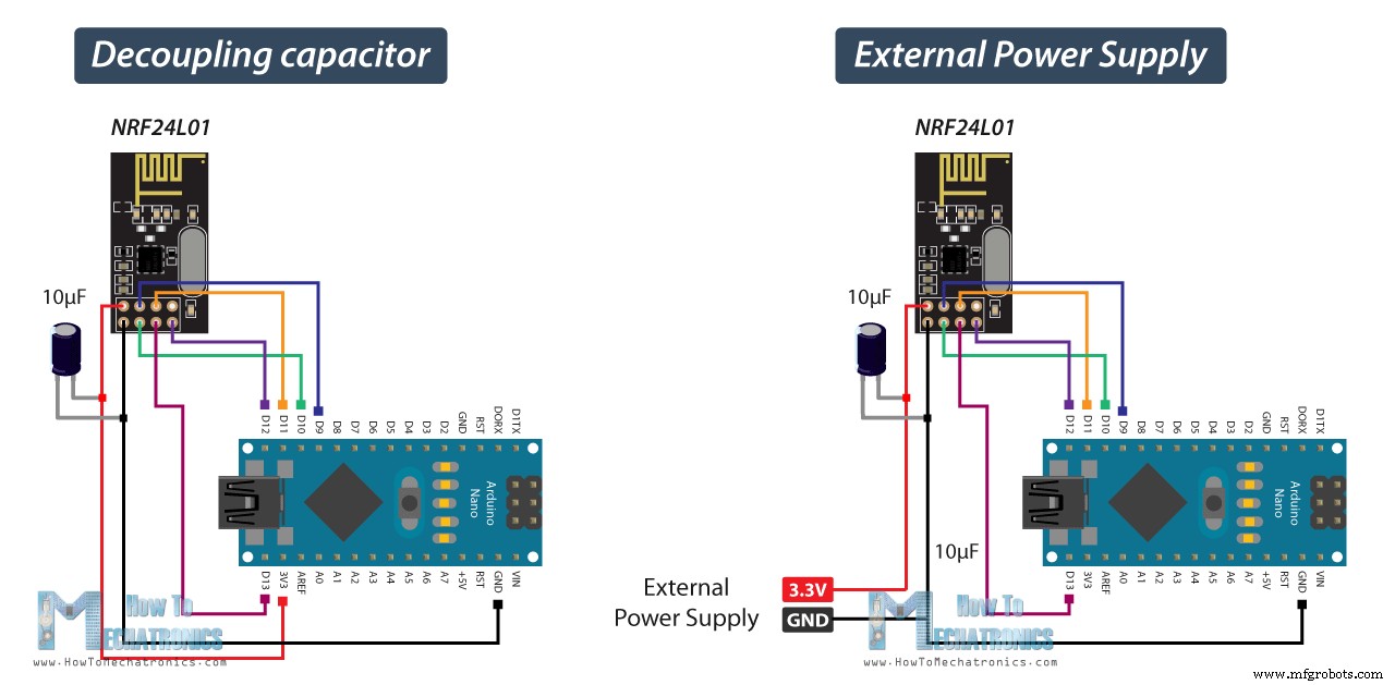
值得注意的是电源噪音 是人们在尝试与 NRF24L01 模块进行成功通信时遇到的最常见问题之一。通常,射频电路或射频信号对电源噪声很敏感。因此,在电源线上加入一个去耦电容总是一个好主意。电容可以是 10uF 到 100uF 之间的任何电容。
另一个常见问题是 Arduino 板的 3.3V 引脚无法始终为 NRF24L01 模块提供足够的电源。因此,使用外部电源为模块供电也是一个好主意。
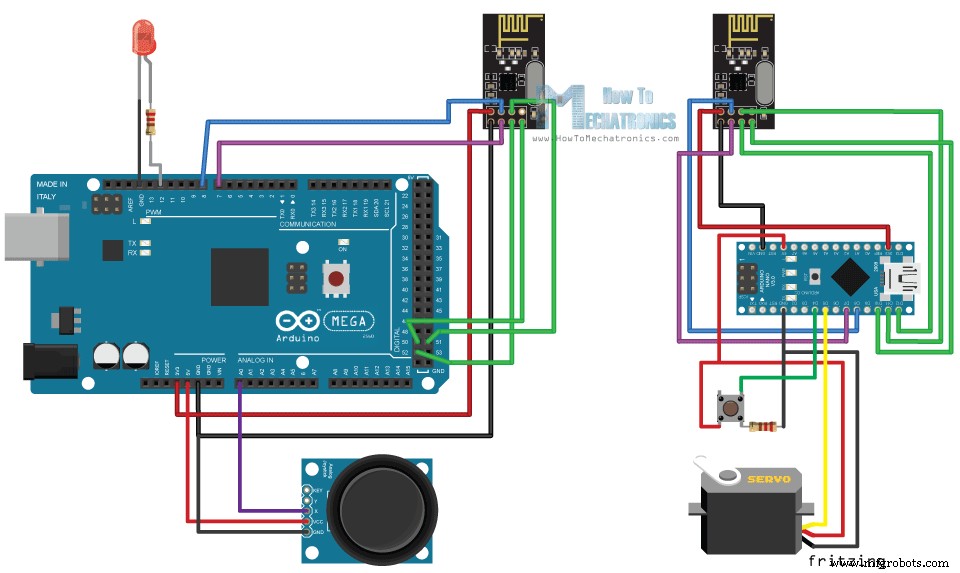
让我们看看第二个例子,两个 Arduino 板之间的双向无线通信。电路原理图如下:
您可以从以下链接获取此示例所需的组件:
下面是这两个代码及其说明。
发射机代码
接收方代码
这里与前面的例子不同的是,我们需要为双向通信创建两个管道或地址。
在 setup 部分我们需要定义两个管道,注意第一个 Arduino 的写地址需要是第二个 Arduino 的读地址,反之亦然,第一个 Arduino 的读地址需要是写地址第二个阿杜诺。
在使用 radio.stopListening() 函数的循环部分,我们将第一个 Arduino 设置为发送器,读取并映射 Joystick 的值从 0 到 180,并使用 radio.write() 函数将数据发送到接收器。
另一方面,使用 radio.startListening() 函数,我们将第二个 Arduino 设置为接收器,并检查是否有可用数据。虽然有可用数据,但我们将读取它,将其保存到“angleV”变量中,然后使用该值来旋转伺服电机。
接下来,在发送器上,我们将第一个 Arduino 设置为接收器,并使用一个空的“while”循环等待第二个 Arduino 发送数据,这是按钮状态的数据,无论是否按下。如果按下按钮,LED 将亮起。所以这些过程不断重复,两个 Arduino 板都在不断地发送和接收数据。
让我们再看一个使用 NRF24L01 模块的示例代码。一切都与前面的示例相同,除了我们构建和发送日期的方式。
发射机代码
所以,我们可以创建一个结构体,它实际上是各种类型变量的集合。
我们应该记住,这个结构数据的最大大小可以是 32 字节。在这里我们可以看到我包含了三个变量类型字节,一个整数变量(4字节),一个浮点变量(4字节)和一个包含四个字符(4字节)的字符串。总共有 15 个字节。
接收方代码
在接收方,我们必须定义相同的结构数据才能接收传入的数据。为了测试无线通信是否正常,我在串口监视器上打印了每个变量。
当您的 Arduino 项目需要无线通信时,NRF24L01 模块是一个很好的选择。我已经在我的许多 Arduino 项目中使用过这个模块。
在这里,我将列出我使用过这些模块的所有项目。
这些项目/教程中的每一个都详细解释了如何使用 NRF24L01 模块,包括电路图、改进的代码实现以实现更好的通信等等。
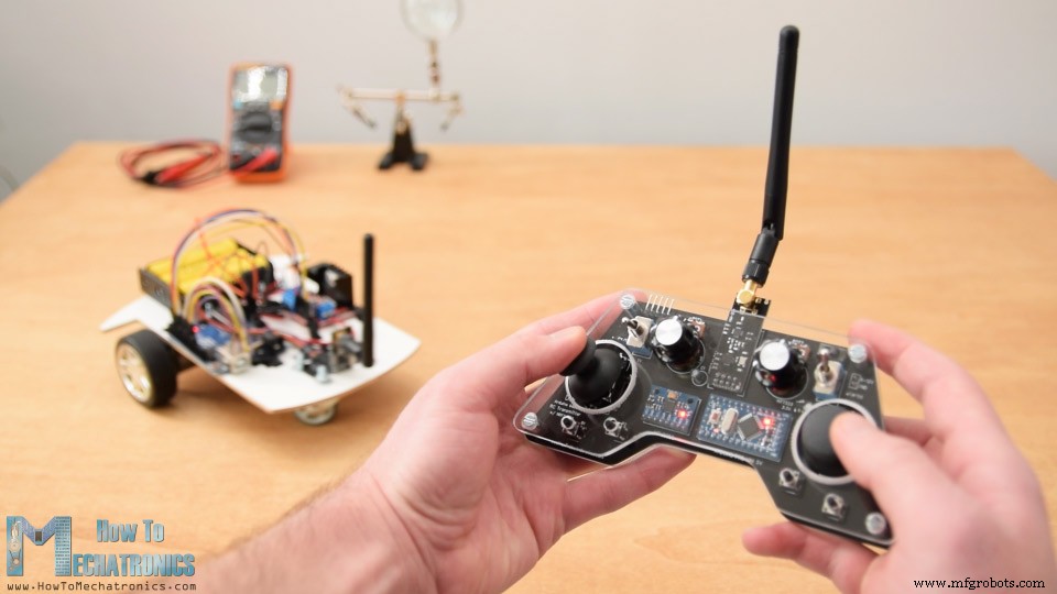
我最喜欢的项目是这个定制设计的 Arduino RC 发射器。它实际上是一个 14 通道 RC 控制器,可用于控制几乎任何 Arduino 项目。
这就是本教程的全部内容,我希望你喜欢它并学到了一些新东西。与往常一样,请随时在下面的评论部分提出任何问题。
概览
nRF24L01 收发模块
频率范围 2.4 – 2.5GHz ISM 频段 数据速率 250Kbps / 1Mbps / 2Mbps 最大。输出功率 0dBm 工作电压 1.9 – 3.6V 最大。工作电流 12.3mA 待机电流 22µA 逻辑输入 5V 容错 通讯范围 100m(空地) 工作原理
模块变体
nRF24L01 模块引脚
如何将 nRF24L01 连接到 Arduino
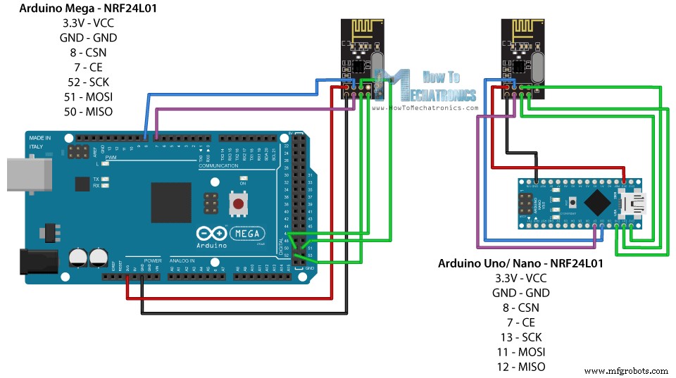
Arduino SCK 味噌 MOSI SS Uno 13 12 11 10 纳米 13 12 11 10 Mega 52 50 51 53
Arduino 和 nRF24L01 代码
发射机代码
/*
* Arduino Wireless Communication Tutorial
*     Example 1 - Transmitter Code
*
* by Dejan Nedelkovski, www.HowToMechatronics.com
*
* Library: TMRh20/RF24, https://github.com/tmrh20/RF24/
*/

#include <SPI.h>
#include <nRF24L01.h>
#include <RF24.h>

RF24 radio(7, 8); // CE, CSN

const byte address[6] = "00001";

void setup() {
  radio.begin();
  radio.openWritingPipe(address);
  radio.setPALevel(RF24_PA_MIN);
  radio.stopListening();
}

void loop() {
  const char text[] = "Hello World";
  radio.write(&text, sizeof(text));
  delay(1000);
}Code language: Arduino (arduino)
接收方代码
/*
* Arduino Wireless Communication Tutorial
*       Example 1 - Receiver Code
*
* by Dejan Nedelkovski, www.HowToMechatronics.com
*
* Library: TMRh20/RF24, https://github.com/tmrh20/RF24/
*/

#include <SPI.h>
#include <nRF24L01.h>
#include <RF24.h>

RF24 radio(7, 8); // CE, CSN

const byte address[6] = "00001";

void setup() {
  Serial.begin(9600);
  radio.begin();
  radio.openReadingPipe(0, address);
  radio.setPALevel(RF24_PA_MIN);
  radio.startListening();
}

void loop() {
  if (radio.available()) {
    char text[32] = "";
    radio.read(&text, sizeof(text));
    Serial.println(text);
  }
}Code language: Arduino (arduino)
代码说明
RF24 radio(7, 8); // CE, CSNCode language: Arduino (arduino)const byte address[6] = "00001";Code language: Arduino (arduino)radio.openWritingPipe(address);Code language: Arduino (arduino)radio.openReadingPipe(0, address);Code language: Arduino (arduino)radio.setPALevel(RF24_PA_MIN);Code language: Arduino (arduino)// at the Transmitter
radio.stopListening();Code language: Arduino (arduino)// at the Receiver
radio.startListening();Code language: Arduino (arduino)void loop() {
const char text[] = "Hello World";
radio.write(&text, sizeof(text));
delay(1000);
}Code language: Arduino (arduino)void loop() {
if (radio.available()) {
char text[32] = "";
radio.read(&text, sizeof(text));
Serial.println(text);
}
}Code language: Arduino (arduino)疑难解答
使用两个 NRF24L01 和 Arduino 进行双向无线通信
nRF24L01 源代码
/*
* Arduino Wireless Communication Tutorial
*     Example 2 - Transmitter Code
*
* by Dejan Nedelkovski, www.HowToMechatronics.com
*
* Library: TMRh20/RF24, https://github.com/tmrh20/RF24/
*/

#include <SPI.h>
#include <nRF24L01.h>
#include <RF24.h>

#define led 12

RF24 radio(7, 8); // CE, CSN
const byte addresses[][6] = {"00001", "00002"};
boolean buttonState = 0;

void setup() {
  pinMode(12, OUTPUT);
  radio.begin();
  radio.openWritingPipe(addresses[1]); // 00002
  radio.openReadingPipe(1, addresses[0]); // 00001
  radio.setPALevel(RF24_PA_MIN);
}

void loop() {
  delay(5);

  radio.stopListening();
  int potValue = analogRead(A0);
  int angleValue = map(potValue, 0, 1023, 0, 180);
  radio.write(&angleValue, sizeof(angleValue));

  delay(5);
  radio.startListening();
  while (!radio.available());
  radio.read(&buttonState, sizeof(buttonState));
  if (buttonState == HIGH) {
    digitalWrite(led, HIGH);
  }
  else {
    digitalWrite(led, LOW);
  }
}Code language: Arduino (arduino)/*
* Arduino Wireless Communication Tutorial
* Example 2 - Receiver Code
*
* by Dejan Nedelkovski, www.HowToMechatronics.com
*
* Library: TMRh20/RF24, https://github.com/tmrh20/RF24/
*/
#include <SPI.h>
#include <nRF24L01.h>
#include <RF24.h>
#include <Servo.h>
#define button 4
RF24 radio(7, 8); // CE, CSN
const byte addresses[][6] = {"00001", "00002"};
Servo myServo;
boolean buttonState = 0;
void setup() {
pinMode(button, INPUT);
myServo.attach(5);
radio.begin();
radio.openWritingPipe(addresses[0]); // 00001
radio.openReadingPipe(1, addresses[1]); // 00002
radio.setPALevel(RF24_PA_MIN);
}
void loop() {
delay(5);
radio.startListening();
if ( radio.available()) {
while (radio.available()) {
int angleV = 0;
radio.read(&angleV, sizeof(angleV));
myServo.write(angleV);
}
delay(5);
radio.stopListening();
buttonState = digitalRead(button);
radio.write(&buttonState, sizeof(buttonState));
}
}Code language: Arduino (arduino)const byte addresses[][6] = {"00001", "00002"};Code language: Arduino (arduino)// at the Transmitter
radio.openWritingPipe(addresses[1]); // 00001
radio.openReadingPipe(1, addresses[0]); // 00002Code language: Arduino (arduino)// at the Receiver
radio.openWritingPipe(addresses[0]); // 00002
radio.openReadingPipe(1, addresses[1]); // 00001Code language: Arduino (arduino)radio.stopListening();
int potValue = analogRead(A0);
int angleValue = map(potValue, 0, 1023, 0, 180);
radio.write(&angleValue, sizeof(angleValue));Code language: Arduino (arduino)radio.startListening();
if ( radio.available()) {
while (radio.available()) {
int angleV = 0;
radio.read(&angleV, sizeof(angleV));
myServo.write(angleV);
}Code language: Arduino (arduino)示例 3 – 在单个包中发送多个变量
/*
  Arduino Wireless Communication Tutorial
      Example 1 - Transmitter Code

  by Dejan Nedelkovski, www.HowToMechatronics.com

  Library: TMRh20/RF24, https://github.com/tmrh20/RF24/
*/

#include <SPI.h>
#include <nRF24L01.h>
#include <RF24.h>

RF24 radio(7, 8); // CE, CSN

const byte address[6] = "00001";

// Max size of this struct is 32 bytes - NRF24L01 buffer limit
struct Data_Package {
  byte a = 0;
  byte b = 125;
  byte c = 255;
  int d = 1024;
  float e = 3.141592;
  String f = "Test";
};

Data_Package data; // Create a variable with the above structure

void setup() {
  radio.begin();
  radio.openWritingPipe(address);
  radio.setPALevel(RF24_PA_MIN);
  radio.stopListening();
}

void loop() {
  // Send the whole data from the structure to the receiver
  radio.write(&data, sizeof(Data_Package));
  delay(500);
}Code language: Arduino (arduino)// Max size of this struct is 32 bytes - NRF24L01 buffer limit
struct Data_Package {
byte a = 0;
byte b = 125;
byte c = 255;
int d = 1024;
float e = 3.141592;
String f = "Test";
};
Data_Package data; // Create a variable with the above structureCode language: Arduino (arduino)/*
Arduino Wireless Communication Tutorial
Example 1 - Receiver Code
by Dejan Nedelkovski, www.HowToMechatronics.com
Library: TMRh20/RF24, https://github.com/tmrh20/RF24/
*/
#include <SPI.h>
#include <nRF24L01.h>
#include <RF24.h>
RF24 radio(7, 8); // CE, CSN
const byte address[6] = "00001";
// Max size of this struct is 32 bytes - NRF24L01 buffer limit
struct Data_Package {
byte a = 0;
byte b = 125;
byte c = 255;
int d = 1024;
float e = 3.141592;
String f = "Test";
};
Data_Package data; //Create a variable with the above structure
void setup() {
Serial.begin(9600);
radio.begin();
radio.openReadingPipe(0, address);
radio.setPALevel(RF24_PA_MIN);
radio.startListening();
}
void loop() {
// Check whether there is data to be received
if (radio.available()) {
radio.read(&data, sizeof(Data_Package)); // Read the whole data and store it into the 'data' structure
}
Serial.print("a: ");
Serial.print(data.a);
Serial.print(" b: ");
Serial.print(data.b);
Serial.print(" c: ");
Serial.print(data.c);
Serial.print(" d: ");
Serial.print(data.d);
Serial.print(" e: ");
Serial.print(data.e);
Serial.print(" f: ");
Serial.println(data.f);
}Code language: Arduino (arduino)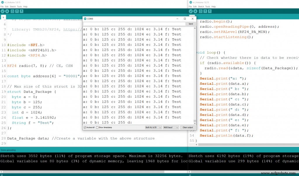
结论
制造工艺