

纳米和电池阳极:综述
摘要
提高负极性能,包括提高其容量,是提高电池性能的基本要求之一。本文介绍了具有合金性能的高容量负极,然后阐述了这些负极碎裂的问题及其在循环寿命中的影响。然后,讨论了将尺寸减小到纳米级在解决碎裂问题和改善性能方面的作用,最后考察了纳米材料的各种形式。在本文中,描述了阳极中的电极还原,这是一种纳米级现象。阐述了这种现象对合金阳极的负面影响,并讨论了如何通过制备合适的纳米结构来消除这些负面影响。此外,还介绍了氧化钛族阳极,并表达了纳米对这些阳极性能改进的影响,最后将介绍纳米特有的准电容行为。最后介绍第三种阳极,交换阳极,并表述其功能。提到了纳米对这些阳极可逆性的影响。描述了这些电极的纳米技术的优点。在本文中,发现纳米技术除了具有减小穿透距离和调节应力等常见效果外,还对此类阳极产生了其他有趣的效果,例如电容准电容、改变存储机制和降低音量变化。
介绍
石墨是一种具有层状结构的碳材料,层与层之间的距离约为 35.3 Å,层与层之间有合适的空间用于放置锂原子 [1,2,3,4]。在充电过程中,锂离子在阳极被还原并转化为锂原子,锂原子位于石墨层之间。锂到达后,极板之间的距离达到 3.5 Å [5,6,7,8,9,10]。在放电过程中,锂原子被氧化成锂离子并通过电解质传输到阴极。由于锂原子嵌入石墨中(在充电时),这些材料被称为插层阳极 [6,7,8,9,10,11,12,13,14]。根据石墨中的图 1,每 6 个碳原子最多可以存储 1 个锂原子 [5]。由于容量与储存的锂量直接相关,石墨的容量比锂金属负极低,但如前所述,它被用作商业负极,因为它没有枝晶生长问题。请注意,在本文和以后的文章中,阳极和阴极是指阳极和阴极中的活性物质 [6,7,8]。由于石墨的低容量,需要具有高容量的阳极 [15,16,17,18]。一组能储存大量锂原子的阳极是由金属或半导体制成的合金型阳极。这些阳极的功能是与金属或半导体形成合金,从而储存锂原子[19,20,21]。在这种类型的材料中,与石墨相比,每 6 个碳原子只能存储一个锂原子,而每个金属原子可以存储几个锂原子 [9,10,11]。这些阳极中最重要的是硅和锑。对于硅,容量约为 4000 mAh/g,而对于锡,上述容量为 900 mAh/g,而石墨的容量约为 350 mAh/g。根据图2,在合金阳极中,硅的体积和重量容量最大,在自然界中发现丰富,整个电子行业都以硅为基础;因此,如图 2 所示,硅是最重要的合金阳极 [12,13,14,15]。因此,本文中的大部分材料都是关于硅的,但所提到的原理可以推广到其他合金阳极。活性负极材料、理论容量、优势及研究结果见表1。
<图片>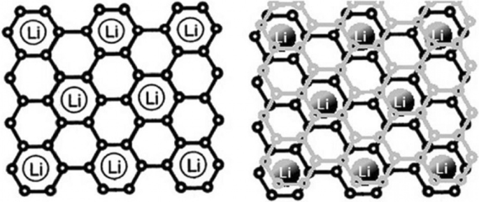
显示锂如何储存在石墨中。每6个碳原子储存1个锂原子[12]
<图片>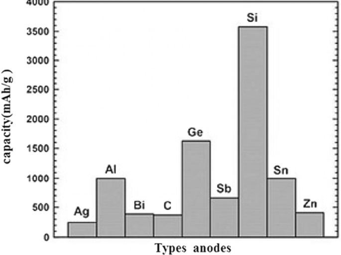
容量负极的种类[13,14,15]
合金阳极问题
在这些负极中,锂的储存和释放伴随着巨大的体积变化,可以达到初始体积的 400%,如图 3 所示。在工作循环期间,由于体积变化引起的应力,发生活性物质粉化现象[7, 10, 39, 40]。碎裂导致活性材料本身之间、活性导电添加剂材料之间以及活性收集活性物质之间的连接被切断 [18,19,20]。当这种现象发生时,活性物质被电隔离;因此,不会发生电子转移以进行氧化反应。因此,大量活性成分未使用且不参与容量,最终这会导致工作周期中容量急剧下降 [21, 41, 42]。图 3 显示了压碎现象。不幸的是,图 3 没有显示阳极电极的整个结构。事实上,在传统的电极中,活性材料的微米颗粒与粘合剂和碳导电材料等一起使用[43,44,45,46]。如果上述电子连接损坏,则损坏。图 4 显示了 10 微米硅颗粒的充电和放电曲线。可以看出,即使在第一次放电时的容量也仅为 800 mAh/g(与最初充电的 4000 相比)。另一方面,在石墨中,每个工作循环的容量仅降低 0.03。这些阳极的电压高于石墨(根据前面所述的公式,阳极电压越高,电池电压越低)[10, 21, 39]。例如,硅的电压比锂高 0.3 到 0.4 伏,而石墨的电压比锂高约 0.05 V,但硅和其他合金阳极的容量如此之高,以至于电压没有显着影响,并且能量明显高于石墨。
<图片>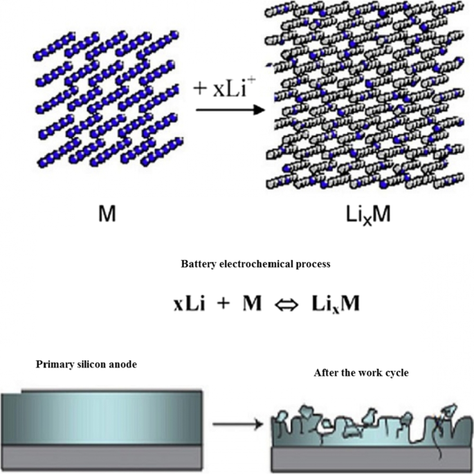
粉化和断开其电气连接[10]
<图片>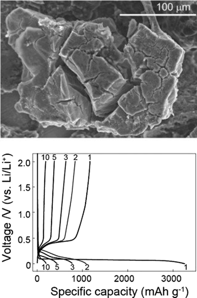
10微米硅颗粒充放电图[17]
纳米技术解决方案
如果可以以某种方式防止碎裂现象,则可以提高电池性能。研究表明,当硅的尺寸达到纳米范围(小于 150 纳米)时,压碎现象不再发生 [47,48,49,50]。图 5 显示了锂离子化过程中硅纳米颗粒的 TEM 图像。由于锂的进入,这两种粒子会改变体积,但不会在应力下破裂 [7, 18, 40]。这说明,要想利用硅的非凡容量,必然要走向纳米级[51,52,53]。如果使用纳米粒子,碎片问题就解决了,但它们通常不连接到电子供应。因此,研究人员首次使用在集电器上垂直生长的硅纳米线,如图 6(SEM 图像)所示。这样就可以解决压碎的问题,因为纳米线之间有足够的空间在占空比期间改变每根纳米线的体积而不产生广泛的应力,每根纳米线的直径也小于临界尺寸[19] ,20,21,22, 30, 54,55,56]。众所周知,合金化(锂的进入)后,纳米线的宽度增加,侧壁变得有纹理,虽然体积变化很大,但没有发生碎片[57]。在纳米线中,电子转移(集电器和活性物质之间的通信)通过纳米线的长度发生。由于电子转移良好,可以使用硅活性材料的全部容量 [31, 32, 35,36,37]。纳米线比大块材料具有更高的电解质键合季节 [41,42,43]。由于氧化反应是通过电极-电解质界面发生的,因此反应速度也会增加。另一方面,由于纳米线与离子必须行进更远距离的大块材料相比具有较小的尺寸,因此通过横向尺寸的离子转移很容易。更快的离子转移和氧化反应会增加功率甚至能量,因为离子转移(有时除了电子转移)是锂电池正负极的电位损失(浓度极化),这种极化随着穿透距离的增加而减小降低,能量密度提高 [44,45,46]。最后,由于硅是半导体,它的电子传导性低于石墨,后者是准金属 [33, 38, 58]。
<图片>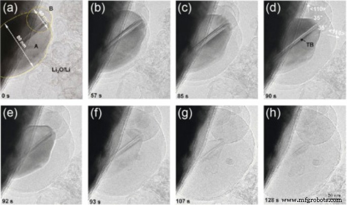
锂离子化过程中硅纳米颗粒的 TEM 图像从 a 进展 h 它锂离子化,分别[19]
<图片>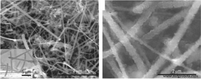
纳米硅在锂过程中的SEM图像[20]
不同的纳米形态
已经表明使用硅纳米管代替纳米线更有效。在纳米管中,为内外壁两侧的体积变化提供了必要的空间[34, 59,60,61]。此外,纳米管通常比纳米线更细,因此发射器更好,因为硅是半导体,并且由于应力在占空比期间也是非晶态的,因此在占空比期间它的电子导电性不佳 [47, 48, 54]。结果,电子在硅的所有部分都不能很好地流动。混合纳米结构可用于解决这个问题,例如其核心包含导电材料的硅纳米管,反之亦然,具有导电涂层 [62,63,64,65,66]。两种类型的未涂层和碳涂层硅纳米线之间的比较表明,碳涂层纳米线保持相当大的容量。另一种解决方案是使用纳米复合阳极 [49,50,51]。纳米复合材料中最广泛使用的材料之一是作为应力调节剂(缓冲剂)的碳。例如,碳领域的碳纳米复合材料就是解决应力问题的方法之一。图 7 显示了锡碳纳米复合材料。锡作为合金阳极的活性成分。这种纳米复合材料中的碳既充当缓冲剂又充当导体,除了具有各种碳结构外,它们还可以储存一些锂。如图 7 所示,由于碳的存在,锡容量小于理论容量 (900 mAh/g),但具有良好的循环寿命。保持良好的工作周期高达 1000 个 [52, 67,68,69,70]。
<图片>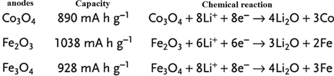
碳、暗锡纳米粒子中锡纳米复合材料的TEM图像和生命周期曲线被标记[54]
鉴于硅具有比其他合金阳极高得多的容量,读者可能会想到为什么正在探索其他合金阳极的问题 [71,72,73]。给出的答案可以概括为整个纳米技术和电池文章的集合,因为纳米材料以不同的方式合成,并以不同的方式具有不同的形态(形状)[74,75,76,77,78]。每种合成方法在价格、质量、安全性、可扩展性、环境影响等方面的讨论不同;例如,金属不能用溶胶-凝胶法制备,这是一种简单的方法 [79,80,81]。即使对于硅等特定材料,也可以通过静电纺丝这种大规模生产的方法,通过昂贵的化学气相沉积方法以纳米线的形式生产纳米纤维等一维纳米材料,这是另一种实验室测试方法[22, 52,53,54]。纳米线可以通过硅蚀刻制造。在后一种方法中,可以容易地控制晶向和掺杂,并且可以确定不同掺杂剂和晶向对锂存储的影响[23, 82,83,84,85,86,87,88]。即使是具有特定形状和成分的纳米材料也可以以不同的方式使用,甚至在特定的方法中,也可以在不同的温度条件下使用不同的反应物等,每一种都可能在价格、安全性等方面产生不同的结果。除了投资之外,商业化的关键是通过考虑上面列出的因素找到合适的生产方法,因此电池的生产和性能之间存在密不可分的联系,非常好的和合适的文章可与合成方法相关[30, 31 , 56, 57, 89,90,91,92]。除了一维纳米结构(纳米线和纳米管)外,还努力使用零维纳米结构(纳米颗粒)(因为好的纳米颗粒比纳米线更容易合成)。纳米粒子的问题在于,一方面不可能轻易地在纳米粒子本身之间建立连接,另一方面在它们与导电和收集材料之间建立连接 [32, 35, 36]。例如,图 8a 显示初级纳米粒子(图像左侧)在充电过程中吸收锂后体积增加,并且在几个循环后,当它返回到没有锂的原始状态时断开电子连接 [3, 24, 93,94,95]。在制备阳极(也是阴极)的常用方法中,活性物质(此处为硅)的粉末与导电碳(以提高导电性)和 PDVF 粘合剂(用于粘合颗粒)一起使用,如图所示在图 8b 中。根据图b,由于硅纳米粒子体积发生变化,回到另一个初始状态后,纳米粒子之间的电连接、碳导电材料丢失,容量降低。为了解决图c所示方法中的上述问题,使用同样具有应力调制作用的非晶硅作为粘合剂,将硅纳米颗粒粘合在一起,使电连接不再中断,容量保持不变[25] , 37, 38, 96, 97]。在另一种方法中,聚苯胺导电聚合物领域中的纳米颗粒既具有调节作用又具有电子传导作用,已经制备并观察到具有1000次的良好循环寿命,同时保持1600 mAh/g的容量。相比之下,PVDF 粘合剂方法在 100 个工作循环中损失超过 50% 的容量。解决问题的另一种方法是中空纳米结构。在这种方法中,在锂通过中空体积进出的过程中提供了必要的空间 [26, 27, 33, 58, 59]。有限元法表明,在相同体积下,空心结构在工作循环中承受的应力较小,因此具有更好的抗压碎现象(图9)。
<图片>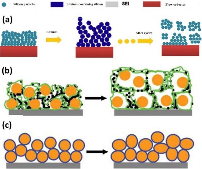
一 显示纳米粒子与集电器的电气关系是如何被破坏的,b 显示另一种类型的断开,橙色的硅纳米颗粒和黑色的碳和 PDVF 聚合物链以绿色显示。 c 使用非晶硅粘合剂即使变形后仍可粘合纳米颗粒[47]。
<图片>
中空纳米粒子解决体积变化问题[48]
阳极中的电解液分解
众所周知,任何物质在电位范围内都是稳定的,并在此范围内或多或少地经历还原或氧化过程 [28, 98, 99]。这就是为什么我们可以分解(电解)水以产生氢气和氧气。这些电池与原电池(电池)相反,称为电解质电池。在这些电池中,与电池不同的是,我们提供能量以迫使发生热力学上不理想的反应 [60]。
给电池充电时,就像分解水一样,我们通过充电器为电池提供能量,以逆转电池中发生的反应,使电池恢复到放电前的状态 [100,101,102,103,104]。锂离子电池中使用的有机电解质(如电解水)会因充电器的能量而发生变化。如前所述,在锂离子电池中,在负极(石墨阳极)处,充电过程中会发生锂离子还原。由于电解液还原的趋势在热力学上高于锂离子,因此进行电解液还原而不是锂离子还原。这导致在石墨表面上形成固体层。该固体层称为SEI(固体电解质界面)。这一层的成分很复杂,是几种化学物质的混合物。图 10 显示了该层的示意图。从图中可以看出,该物质的成分含有锂离子和碳;因此,该层的形成伴随着锂的减少,从而降低了第一次充电的容量 [34, 61]。这层厚度在纳米范围内,如图 10 所示。SEI 层的形成本身限制了电解质还原反应的继续,因为它阻止了电解质分子作为物理屏障到达石墨阳极表面。事实上,它起到了动力学抑制剂的作用(就像氧化铝的钝化层,它可以防止氧气到达较低的铝并防止其余的铝氧化)。另一方面,因为它是电子绝缘体,它也阻止电子到达电解质[62,63,64,65]。因此,电子不能到达电解质分子,电解质分子也不能向阳极中的电子移动,这两者都会导致电解质再生并发生自限反应。幸运的是,这一层对锂离子是可渗透的,锂离子可以通过它到达阳极表面,捕获电子并再生[105,106,107,108]。该层降低了电池功率,因为它增加了锂离子到达阳极的穿透距离[109,110,111]。
<图片>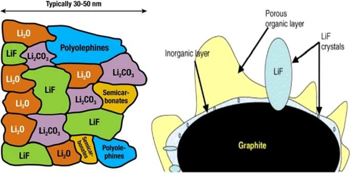
该层SEI形成和组成示意图[66]
图 11 显示了相对于阳极和阴极电位的电解质稳定性范围。如果阴极的电位高于电解质稳定范围,则电解质在阴极和充电过程中被氧化,如果阳极电位低于稳定范围,则在阳极和电解质充电过程中再生。幸运的是,如图 11 所示,常规正极不存在电解质不稳定的问题,但在石墨和硅负极中存在不稳定并形成 SEI [66,67,68]。
<图片>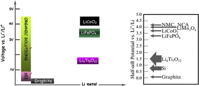
显示了共阳极和阴极的电压以及电解质稳定电位范围和SEI形成电位范围[67]
硅中的 SEI 问题
通常,对于相对于锂金属小于 1 伏特的阳极,电解质不稳定并形成 SEI。因此,SEI 在硅负极中形成,其电位比锂高 0.3 至 0.4 [112,113,114,115]。不幸的是,由于硅改变体积并分解,新水平的硅暴露在电解质中,因此电子到达电解质并在这些新表面上形成新的 SEI。因此,在工作周期中,容量不断降低。有必要这样说,因为测试通常是在锂金属上进行的,所有电池产品中都测量了相对于锂的电压[69]。在硅纳米材料中,由于化学活性较高,更容易形成SEI。就纳米材料而言,它们确实不会分解,但确实会改变体积。根据图 12,这种体积变化导致 SEI 不断增长,我们看到 SEI 增长的缺点,例如容量和功率降低等。部分 a 的图 13 更好地说明了纳米材料中 SEI 生长的原因。如果我们在初始状态下没有锂的纳米线(或纳米粒子等)的横截面,如图左侧所示,在充电过程中,由于硅是含锂的,它的体积增加并且由于电解质同时在纳米线上形成 SEI 层 [116,117,118,119]。现在在放电过程中,锂出来,粒子收缩,而 SEI 不收缩。这会导致 SEI 在应力下崩溃(甚至在锂离子化下硅增大的第二阶段,此时应力发生并且 SEI 崩溃,因为 SEI 和粒子之间的确切边界不完全匹配)。因此,在充电(锂离子化)时,会再次形成新的 SEI 层。这个循环的重复导致 SEI 持续增长,我们在增长方面存在问题,而石墨 SEI 不会在其体积略有变化的情况下增长。应该注意的是,关于 SEI 和硅的讨论也适用于其他合金阳极 [70, 120,121,122,123]。如b节所示,这个问题也存在于硅纳米管中,但如果我们能以某种方式阻止硅从一开始就与电解液接触并改变其在电解液附近的体积,这个问题就会得到解决。
<图片>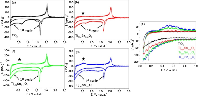
SEI层是如何生长的[19]
<图片>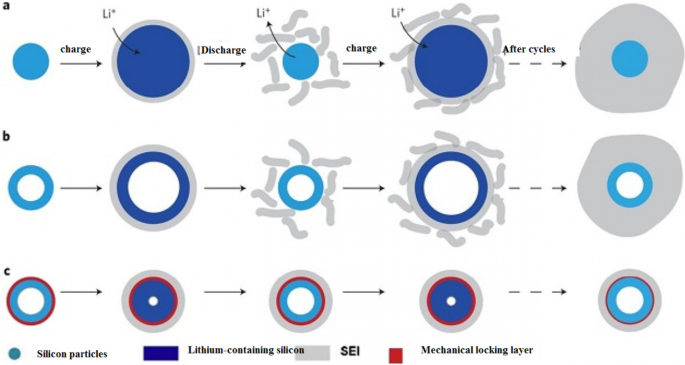
显示了不同条件下SEI的增长[20]
吴等人。 [18] 使用了机械锁定层,如图 13c 所示;该层由氧化硅制成,由于其机械强度,可防止纳米管外部体积发生变化。因此,在不改变体积的情况下形成稳定的 SEI(像石墨一样的稳定 SEI 层)。该氧化物层是锂离子的导体,因此不会引起反应问题。还通过纳米管的内壁提供了体积变化所需的空间。所以不存在压碎的问题。因为研究表明电解质没有渗透到纳米管中,所以电解质和纳米管内壁之间没有接触。所有这些优点使其具有较长的循环寿命和良好的功率。图 14(在此图中显示了 DWSiNT)显示了该样品的部分深度放电循环。在深度放电中,循环寿命总是缩短得更快。然而,观察到900次循环后,制备的样品仍具有良好的容量,但正常的纳米管和纳米线样品迅速失去容量。放电)对于绘制的样品,它表明即使在这种相对较高的 C 倍率之后,即使在高达 6000 次开路循环后,容量仍能保持其容量。在另一个例子 [19] 中,制备了核壳结构,如图 15c 所示,使用碳涂层,在碳涂层内使用硅纳米颗粒。碳涂层的厚度在 10 纳米范围内,包括 100 纳米的硅颗粒。碳壳有足够的空间,可以很容易地改变硅纳米粒子的体积,如图c所示。另一方面,硅纳米颗粒从一个点附着在碳壳上,因此在其中发生电子和离子跃迁,因为碳在电解质附近而不是硅,如石墨,形成稳定的 SEI,不会破碎因为硅的体积变化没有转移到碳上,也没有从碳转移到 SEI,所以类似于图 12 中的图,它具有很长的循环寿命。如果我们正常使用硅纳米颗粒,除了SEI问题,正如我们在上一篇文章和图a中看到的,表明硅纳米颗粒之间没有空隙来改变体积,所以当颗粒之间存在应力时它们会改变体积,但是当使用这种中空结构(图 b)时,颗粒之间不再有任何应力。
<图片>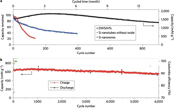
一 氧化膜黑色、蓝色和红色循环寿命比较,b 分别为无氧化物和非氧化物纳米管 [21]
<图片>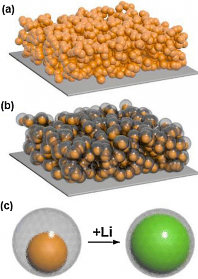
一 显示由硅纳米颗粒制成的电极。 b 由具有碳涂层和中空结构的硅纳米颗粒制成的电极显示器。 c b中使用的空心壳结构 , 硅在空心碳内部,在锂离子化过程中观察到其体积变化 [10]
与图 12 中的样品相比,除了 SEI 问题之外,该阳极还具有其他优势。纳米颗粒合成优于纳米管的一个优势,更重要的是,与纳米线相比,纳米颗粒的使用与浆液法非常兼容,这是制备电池电极的常规方法。
介绍 LTO 阳极
到目前为止,我们已经讲了两种类型的石墨阳极和合金(硅)阳极。另一种非常流行的阳极是Li4Ti5O12化合物的阳极,简称LTO。该阳极类似于嵌入石墨 [29, 124,125,126,127]。图 16 显示了此类阳极的结构和反应。 LTO 阳极的容量有限,为 175 mAh/g(与 300 石墨和 4000 硅相比)。根据图 17,与锂金属相比,该阳极的电压也约为 1.5 V(阳极电压越低,电池电压越高)。 This high voltage and low capacity both make this anode have very low energy, but it is still one step ahead of silicon in commercial terms. One of the most important features of this anode is the safety issue, because in electric vehicles there are unpredictable conditions, and the other is the long cycle life, and finally its power [72, 73, 128,129,130].

Shows the structure and entry of lithium ion in LTO along with its reaction [74]

a Displays the nanostructure discussed including Nano primary nanoparticles, b charge–discharge curve for ordinary micro particles, and c for a-shaped particles [74]
Due to the fact that the voltage of this anode is high, it is in the range of electrolyte stability according to Fig. 17, so SEI is not formed. On the other hand, as shown in Fig. 17, there is enough space for lithium ions in this composition and it does not change volume, while even in graphite, some volume change is seen due to the entry and exit of lithium. Unlike the previous two anodes, lithium ions (not lithium atoms) are stored in this anode, and the oxidation reaction is due to the conversion of titanium to 3-valent titanium, not to a change in lithium capacity [28, 74, 75, 131].
This battery, because it has neither SEI nor volume change, maintains the capacity well and has a very long cycle life (more than graphite) of about 20,000 cycles. Because it is an oxide compound and is very safe due to the lack of volume change. Because it does not have SEI, its power is not bad either, only its lithium ion diffusion coefficient is low and its electron conductivity is poor. To solve this problem, they provide LTO nanostructures. Because this anode did not have SEI from the beginning, when it becomes Nano, it does not have the problem of forming more SEI, so it does not have more nanomaterial activity [32, 35,36,37].
It has been observed that nanoparticles cause the LTO anode to charge and discharge within 5 min (12C). To prepare the nanostructure, first titanium oxide nanostructure is prepared and then reacted with a lithium source material when heated. This is also an advantage of LTO, as the preparation of TiO2 nanostructures is very popular. Due to the problem of low volumetric density and agglomeration of nanomaterials, micron secondary particles made from nanoscale primary particles are more useful [33, 38, 58, 59].
Figure 17 shows part an of this nanostructure. As can be seen, from the controlled community of smaller particles measuring 10 nm, larger micron particles are formed. According to the comparison of parts b and c in Fig. 17, it is quite clear that this nanostructure is superior to ordinary micron particles, because it has less capacity and potential (especially in discharge). From this nanostructured anode, a battery is made and it is observed that this battery is superior to the battery with graphite anode both in terms of cycle life and power, which is not given due to the brevity of these curves [75]. The benefits of Nano-LTO have been well documented in many articles, but what makes it stand out is an important discussion of proper engineering of the structure, proper synthesis method, and how to use the conductive material to improve conductivity for further improvement. The future will be talked about. In addition, it is not disputed that nanotechnology is useful for LTO, but many of the phenomena that occur at the nanoscale for LTO are discussed so that some are not fully understood.
Another phenomenon that occurs at the nanoscale is the change in charge–discharge curves for the LTO anode. This anode provides a constant voltage over a wide range of capacities (red box in Fig. 18). When LTO ions are Nano, the constant voltage range decreases until after a critical limit (in the range of a few nanometers) there is no longer a constant voltage range [76].

Shows the linear curve range at the LTO anode in the charge–discharge axis [75]
One of the things that happens on the surface is the insertion of more lithium ions into the surface layers. In the surface after insertion, we reach the formula Li8.5Ti5O12, which is 1.5 mol more than the inner layers with the formula Li7Ti5O1, but in the micron material, because the percentage of surface is not high, it shows its effect, but for Nano, because the amount of surface is large, the effects are large. There are several on the charge–discharge curve.
TiO2 Anode
There is also a TiO2 anode from the LTO family. These anodes are easier to synthesize, and because they do not want to react with heat-induced lithium ion precursors, they do not have heat-induced problems such as nanomaterial growth. In addition, according to the chemical formula, titanium oxide has a capacity of twice the amount of 335 mAh/g (LTO). The general response of these anodes is \({\text{TiO}}_{2} + x{\text{Li}}^{ + } + xe^{ - } \leftrightarrow {\text{Li}}_{x} {\text{TiO}}_{2} .\)
TiO2 has four types of phases or crystallographic structures (different atomic arrangements) known as Brocket, Anastasi, Rutile, and (TiO2 (B). The Brocket phase does not matter to the battery. Antara and rutile, which are very popular phases, are important as anodes. Phase (TiO2 (B) performs better than others due to its atomic open space and suitable channel for ion transport, and is the most important [75, 76, 132,133,134,135,136].
If we consider the theoretical capacity based on the chemical formula (one mole of lithium ion per mole of TiO2), it is equal to the above value, but based on the phase and position that can be placed according to the lithium ion crystal lattice, different theoretical capacities for different phases have been reported; for example, for anisate, according to network sites, the half-capacity is high, 0.5 mol of lithium ion per mole of TiO2, 167 mAh/g.
Because all of these phases have poor ionic conductivity, the nanoscale is very effective in increasing both power and capacity. What is interesting is that the nanostructured capacity of Anastasi is more than the theoretical capacity based on the position of the network, but it is definitely less than the theoretical capacity of Formula 334 in all phases. Rutile in micron mode can only store 0.1 mol of lithium ion per grid unit. In rutile, lithium locations are located throughout the network, but the diffusion coefficient in the direction of the c -axis is one order of magnitude greater than that of the ab plate [137,138,139,140,141]. The lithium atom penetrates well in the direction of the c -axis, but must be diffused throughout the space by penetrating the ab plane, and because the diffusion velocity is low in the ab plane, lithium ions accumulate in the c channel, causing a charge repulsive force. Lithium ion positive is generated. This repulsive force prevents more ions from entering the network. As an interesting result of the Nano effect, it has been shown that when the dimensions of rutile become Nano, the capacity reaches 0.8 mol of lithium ion, which has a reversible capacity during different cycles, which reduces the penetration distance and the effect of its quadratic power [142,143,144,145,146]. There is no repulsive force. Figure 19 shows the charge and discharge curves and the cycle life for rutile bulk (micron), commercial rutile micro particles, and rutile nanowires. As can be seen, nanowires show good cyclic longevity and capacity. The shape also confirms that the shape of the nanomaterials also affects the performance of the anode. Morphology such as nanoparticles, nanowires, etc. differ in both capacity and life cycle and power, but the type of morphology alone is not decisive but the geometry of the structure that determines the performance (in the future about the geometry of the structure for all active materials for example, nanowires connected to a current collector, nanowires mixed with graphene, and insulated nanowires each present different results. In addition, there are test conditions and C rate and many other factors [77]. Phase (TiO2 (B), which is newer than other phases, offers the best power and capacity due to its suitable channels for lithium ion transport [147,148,149,150,151]. Figure 20 shows the structure of the penetration site. The capacitance can be significantly increased. This phase offers the best power and capacity among all titanium anodes including LTO, so that by Nano partying it in just 4.5 s, the anode can be charged or discharged with a capacity of 73% of theory. We do not have volume change in this anode either.

a Charge–discharge curve for the first time, b cycle life [77].

Showing the atomic structure of the phase (TiO2 (B) [77]
Quasi-capacitive Capacity
So far, it has been discussed about the storage capacity of lithium ions in the form of a degree in the nuclear network, and this capacity is improved in the nanoscale due to the reduction of the penetration distance, and so on [152,153,154,155]. But one of the interesting phenomena that occurs for these anodes at the nanoscale is the storage of lithium ions at the surface due to the large surface-to-volume ratio. This type of storage is different from the insert and alloy capacity mentioned so far. This type of storage is very fast because it does not require penetration, and also because it does not create stress and the like, it has the best cycle life and power compared to other lithium storage methods [156,157,158]. Of course, this type of capacity generates less energy. This capacity is discussed in more detail in the topic of super capacitors. The Fig. 21 shows a comparison between the storage capacity of LTO capacity in three different Nano dimensions [78]. According to Fig. 21 in small Nano dimensions, this capacity is significant and decreases significantly with increasing dimensions. It should be noted that capacitive capacitance is not only related to titanium oxide compounds but is also present in many other active substances that are mentioned when introducing them.

Demonstration of input and super capacitor capacities in titanium oxide [78]
Introduction of Exchange Anodes
So far, we have talked about two types of insert electrodes and alloys. The third type of electrode operation is based on a conversion reaction. Figure 22 shows the mechanism and reaction of this type of electrode. In this form, M (or Me) is an intermediate element that is oxidized, and X is an anion such as oxygen, sulfur, and the like [159,160,161]. The advantage of these anodes is that for every MxXy unit, n lithium ions (n more than one) are involved in the reaction, whereas in the graphite insert anodes we see one lithium ion for every 6 carbon atoms stored in titanium compounds. A maximum of one lithium ion is stored per TiO2 formula unit. But in the exchange anode, for example, for CoO and FeO, the value of n is equal to 2, and in Co3O4, the value of n is equal to 8. Figure 23 shows a number of exchangeable oxide anodes with their reaction and capacity [22, 30, 55].

Shows the structure and entry of lithium ion with its reaction [22]

Shows the reaction and capacity of a number of conversion oxide anodes [30, 55]
Exchange Anode Problems
Exchange anodes are very similar to alloy anodes, as alloys have problems with volume change, fragmentation, and SEI formation. In these anodes the ionic and electron conduction is low, and in addition the exchange rate is slow. This low speed leads to high potential during charging and discharging. At these potentials, there is a large difference between the charging and discharging voltages, called hysteresis, which is shown in Fig. 24 with a red arrow. This figure shows that in the first stage of lithium extraction, the anode behavior is significantly different from the next stage of charge and discharge. The hysteresis in this type of anode is up to one volt, while in the graphite and LTO anode it is about 0.2 V. This hysteresis is mostly due to activation polarization [78, 79].

Show charge–discharge curves of exchange anodes [79]
Nano Sizing Effects
Figure 25 shows the lithium ionization behavior (in the test mode, against lithium metal) for anodes made of fine nanoparticles (20 nm) and micro-nanoparticles (500 nm) of iron oxide (SEM) images of these particles in Fig. 26. Available it can be seen that the capacity of the Nano anode is slightly higher. More importantly, it can be seen that the charge–discharge behavior of these two anodes is very different from each other, which is examined in Fig. 26. Figure 26 shows the charge–discharge curves in different cycles as well as the cycle life for the same samples in Fig. 25 to determine the reason for the difference in charge–discharge curves in Fig. 25. Note that instead of capacity, lithium that enters and leaves (which, according to the arguments, represents capacity) is used. In the charge–discharge curves of Fig. 26, lithium ionization continued only up to 1 mol because its purpose was to investigate the behavior in this range of lithium ions. As can be seen, the effective surface mass for the material is only 2 m 2 /g while for the Nano it has an effective surface area of 60 m 2 /g, which indicates how much higher the effective surface area is at the Nano. The difference between Nano and Nano performance is also quite clear. As shown in Fig. 26, the amount of reversible lithium (which can be removed during charging) for Nano is much higher than the corresponding amount for bulk. This shows that the capacity that can be recovered after the initial charge is much better in Nano than in micro. Also, according to the same figure, in the next consecutive charge-discharges, the amount of lithium entering and leaving is less than 0.25 (from 0.75 to 1), while for Nano, the amount of lithium entering and leaving is more than 0.5 (the amount of lithium ion). In the composition it has changed from the range of less than 0.5 ions to 1 ion), according to this, the capacity offered in Nano is much more than bulk. In the micron-sized anode of Fe2O3 (hematite), before the exchange reaction begins, about 0.1 mol of lithium ion per mole of oxide compound can be stored in the lattice, but above this critical limit, the exchange reaction takes place; on the other hand, when we increase the dimensions of iron oxide particles to 20 nm, the amount of lithium stored in degrees reaches 1 mol, which causes a volume change of only about 1%. Of course, about 0.5 mol is reversible (Fig. 25). In fact, the type of storage mechanism (input, exchange, etc.) changes and the type of mechanism affects the shape of the charge–discharge curve. The above paragraph indicates that when the oxide dimensions enter the Nano field, the storage mechanism is also affected. So far it has been said that Nano makes volume change easier without failure, but here it can be seen that even Nano has reduced the amount of volume change from a few percent for the exchange reaction to one percent for a degree reaction. The reason for this change is the storage mechanism for iron oxide due to thermodynamic problems. The opposite happens for the Co3O4 anode because it is kinetic and is related to the current density (the current density is obtained by dividing the current by the surface); when the current is constant, in the Nano-dimensions, because the surface is higher, the current density decreases and the Co3O4 anode shows exchange behavior, but in the micro, due to the high current density, the anode shows the insertion behavior [76,77,78,79].

Demonstration of lithium ionization for n -Fe2O3 and micro-M-Fe2O3 [80]

Display of SEM images, charge–discharge curves and cycle life for Nano-iron oxide and bulk [80]
It can be seen from Fig. 26 that at the nanoscale, the cycle life is also much better than bulk. The reason for the improvement of these expressed properties is the ease of volume change and release of stress, ionic and electronic transitions are easier due to the reduction of the penetration distance, which was expressed in this series of articles. Due to high hysteresis, less attention has been paid to compounds with hysteresis [22, 51,52,53,54, 80].
Nanomaterials in Batteries
Nanomaterials have been widely applied in the life sciences, information technology, the environment, and other related fields. Recently, nanostructured materials have also attracted attention for application in energy storage devices, especially for those with high charge/discharge current rates such as lithium ion batteries. The development of next-generation energy storage devices with high power and high energy density is key to the success of electric and hybrid electric vehicles (EVs and HEVs, respectively), which are expected to at least partially replace conventional vehicles and help solve the problems of air pollution and climate change. These energy storage technologies will rely on innovative materials science, i.e. developing electrode materials capable of being charged and discharged at high current rates. Generally, the potential advantages of nanostructured active electrode materials can be summarized as follows:new reactions can be used that are not possible with bulk materials; a larger electrode/electrolyte contact area, leading to higher charge/discharge rates; short path lengths for both electronic and Li ion transport (permitting operation even with low electronic or low Li ion conductivity, or at higher power); etc. Here, we review some recent experimental results that show the advantages of nanostructured active electrode materials [147]. Table 2 summarizes the nanotechnologies that are used to produce nanomaterials, such as mechanical ball milling, chemical vapour deposition, the template method, electrochemical deposition, hydrothermal reaction, dehydration, sintering, pulsed laser deposition, ultrasound, sol–gel synthesis, and micro emulsion.
The first group of applications of nanotechnology in batteries is itself divided into two categories:the first group nanoscale the active substance in the electrode, the second group use nanotechnology to improve the performance of electrodes (cathode or anode) by adding nanomaterials other than the active substance, or the use of Nano coatings. For example, Nano-dimensional additives such as Nano carbons, graphene, carbon nanotubes, etc. have better electron conduction, or the use of Nano-thick coatings on the active material to prevent unwanted reactions with the electrolyte, stress modulation, provide stability and ….为了它。 For example, for a LiFePO4 cathode, the amount of electron conductivity is poor. Conductivity is improved by using a conductive carbon coating on its particles or by using a conductive carbon material as an additive, A Nano-thick coating of oxide is used [83, 94, 172,173,174,175,176,177]. For example, for a LiFePO4 cathode, the amount of electron conduction is poor, Conductivity is improved by using a conductive carbon coating on its particles or by using a conductive carbon material as an additive, or the LiCoO2 cathode is unstable at high currents in the vicinity of the electrolyte, using a Nano-thick oxide coating to stabilize it [162, 163, 178, 179]. If we want to illustrate the field of nanotechnology in this category with an example, in the same LiFePO4 cathode it has been shown that carbon coating increases conductivity and consequently power, capacity, etc., but one of the areas of research is how to create this coating. Be cheap, effective, etc.; therefore, research in the field of synthesis methods is very important. On the other hand, how to add the same coating and additives to be more effective, so the engineering and architecture of nanostructures is one of the important areas of research and the preparation of these engineered structures is also an interesting issue. Consider Fig. 27 to clarify the matter. This figure shows two types of Nano-engineered structures for the LiFePO4 cathode that use carbon nanotubes to improve conductivity. In addition to differences in performance, each of these structures has a different synthesis method, which indicates the importance of synthesis.

a , b With carbon nanotube core and LiFePO4 wall, and Figure c LiFePO4 nanoparticles attached to carbon nanotube [3, 93]
Silicon has attracted tremendous attentions as one of the most promising candidates for the next-generation Li-ion batteries (LIBs). Compared to the traditional graphite anode, it has many obvious advantages such as large capacity, high abundance and environmental friendliness [1,2,3,4]. Unfortunately, due to the huge volume expansion (~ 300%) in lithiation, silicon particles are pulverized and solid electrolyte interphase (SEI) layers formed on their surface are unstable. Therefore, the long-term cycling stability of silicon anode is poor [5,6,7,8]. Moreover, the low intrinsic conductivity of Si causes unsatisfying rate-capability [9,10,11,12]. Thus, a large amount of Si/metal (e.g., Ag, Cu, Al, Sn) composites have been developed to solve the low conductivity [13,14,15,16]. However, the large volume expansion cannot be relieved effectively. On the other hand, carbon Nano layers are coated on the electrode materials to increase their conductivity, enhance their mechanical strength and provide them stable interfaces with electrolyte. Therefore, various conformal carbon layer coated silicon (Si@C) nanostructures are developed. For example, Si@C with core–shell structure are formed by pyrolyzing various precursors (e.g., pitch, glucose) to coat carbon layers on the pre-prepared silicon nanoparticles [17,18,19,20,21].
崔等人。 designed a hierarchical pomegranate-structured Si@C composite and a nonfilling carbon-coated porous silicon micro particle via the pyrolysis of resorcinol–formaldehyde resin (RF), respectively [23, 82]. And Yu et al. prepared double carbon shells coated Si nanoparticles via chemical vapor deposition (CVD), with acetylene as carbon source [24]. All these designs provide sufficient voids to allow large volume changes of Si during the lithiation/delithiation. However, most of Si@C composites were prepared in separate steps by either pre-coating or post coating carbon on silicon nanomaterials. It led to a complicated preparation strategy.
Continued interest in high performance lithium-ion batteries has driven the development of new electrode materials and their synthesis techniques, often targeting scalable production of high quality nanoceramics (< 100 nm in diameter), which may offer performance improvements. However, there are a number of hurdles, which need to be overcome to move away from current batch synthesis methods that offer poor reproducibility or lack of control over crystallite attributes, particularly at larger scale syntheses. Continuous hydrothermal flow synthesis (CHFS) processes are a promising route for the direct and controlled manufacture of Li-ion battery electrode nanoceramics. Such processes use superheated water and metal salt mixtures as reagents. In a typical CHFS reaction, a feed of supercritical water (above the critical point of water (TC = 374 °C and Pc = 22.1 MPa), is rapidly mixed in an engineered mixer [1] with a metal salt/base aqueous precursor feed (at ambient temperature and the same pressure), resulting in rapid formation of the corresponding nanocrystallite oxide in the water. This nucleation dominated reaction occurs as a result of the metal salts being supersaturated upon mixing with sc-water and also instantly being hydrolysed and dehydrated under these exotic reaction conditions. The nascent nanocrystallite metal oxide stream in water is then cooled in process and then can be constantly collected from the exit of the CHFS process as an aqueous nanoparticle slurry at ambient temperature. The cleaned crystallites (e.g. via dialysis) can be obtained as a wet solid and then freeze-dried to retain maximum surface area and reduce agglomeration. Compared to batch hydrothermal syntheses, CHFS type processes typically produce very small nanoparticles (< 10 nm) with a narrow size distribution [2,3,4]. Additionally, CHFS processes are highly scalable (> 1 kg per hour in the lab of the UCL authors [5]) and can be used to make high quality nanoparticles at scale, with little or no significant variation between those made on the smaller CHFS laboratory scale process.
Cyclic voltammetry (CV) measurements at a scan rate of 0.05 mV s −1 in the range of 0.05–3 V versus Li/Li + , are presented in Fig. 28. A pair of cathodic and anodic peaks were observed in the potential range 1.5 and 2.3 V versus Li/Li + , relating to Li-ion insertion into and extraction from the interstitial octahedral site of TiO2 (see equation) [81]. Under normal circumstances, a two-phase reaction is expected to occur during lithiation with phase equilibrium of the Li-poor Li0.01TiO2 (tetragonal) phase and the Li-rich Li0.55TiO2 (orthorhombic) phase [19, 20]. The detected specific current peak decreased with higher amount of Sn, thereby reducing the amount of pure TiO2. The pure TiO2 sample showed virtually no electrochemical activity in the potential range between 1.3 and 1 V versus Li/Li + during the first cycle. The increasing specific current during the first cycle between 1 and 0.05 V versus Li/Li + , is attributed to solid electrolyte interface (SEI) formation (electrolyte destruction) at lower potentials [13]. There was also likely to be substantive SEI formation at the crystallite surfaces of the Sn-doped materials compared to the undoped TiO2, as there was significant electrochemical activity in the range of 1.3 to 1 V versus Li/Li + for the former. However, as the surface area decreases with higher Sn-loading, the initial capacity loss due to the SEI formation may be expected to decrease. The general trend in fact showed that with higher Sn-loading, the initial irreversible capacity loss increased (from 363 mAh g −1 for the pure TiO2 and 467 mAh g −1 for Ti0.85Sn0.15O2).

Cyclic voltammograms for the 1st and 2nd cycles for the as-prepared Nano-powder in the potential range of 0.05 and 3 V versus Li/Li + for an applied scan rate of 0.05 mV s −1 for a undoped anatase TiO2, b Ti0.94Sn0.06O2, c Ti0.89Sn0.11O2, and d Ti0.85Sn0.15O2. e Specific current versus potential of the 2nd cycle for all materials at lower potentials. The specific current was calculated by taking into account the active material mass loadings [81]
Conclusion
- 1.
This article discusses silicon anodes as a representative of alloy anodes. It was observed that the only solution to solve the shredding problem is to use nanotechnology. In this paper, the importance of nanomaterial synthesis was expressed. In summary, how to use nanomaterials with different morphologies to solve the problem and improve power. Although various morphologies were discussed, there was no discussion of structural engineering and the use of carbon conductive materials, which will be discussed in future articles. This was one of the methods of establishing electrical bonding for nanoparticles. There are various structures to prevent the nanoparticles from breaking, the art of which is to create different geometries and the method of their preparation.
- 2.
This article discusses SEI, which is one of the most important topics in most anodes and some high voltage cathodes. This article discussed the problem of alloy anode fragmentation, while which is due to the continuous growth of SEI. It turned out that in order to have a proper cycle life, this problem must be overcome. According to the given examples, using a suitable design at the nanoscale, in addition to providing free volume change of silicon, this volume change does not occur in contact with the electrolyte.
- 3.
The carbon coating on the anode can increase the conductivity from 13–110 to 2.05 S/cm. Doping can enhance performance by increasing the conductivity of electrons and even ions and providing more space within the network along with Nano sizing, which may be appropriate for new projects, which is more a Nano-topic in Nano synthesis than how it accompanies matter. Synthesize with Nano-dimensional doping until there is a discussion about the effect of Nano on improving anode performance. This article discusses titanium oxide anodes, which is one of the most commercially important anodes. It was found that nanotechnology greatly improves the performance of these anodes. Nano sizing has also been shown to affect even the electrochemical and chemical-physical nature (such as charge–discharge curve deformation and greater capacity in surface layers).
- 4.
In this paper, exchange anodes are introduced and their complex operation is described. It was found that many problems, such as alloy anodes, can be solved by Nano damaging the active material. The special effects of Nano were expressed as a change in mechanism.
Availability of Data and Materials
All data generated or analyzed during this study are included in this published article.
纳米材料
- 回顾 R、X 和 Z(电阻、电抗和阻抗)
- 可靠性和精益计划 Power Energizer Battery Plant
- 用于未来电池的锡纳米晶体
- 生物传感器和纳米传感器在农业生态系统中的应用综述
- 用于超级电容器应用的石墨烯和聚合物复合材料:综述
- 面向多孔和空心结构 LiNb3O8 阳极材料的水热辅助烧结策略
- 通过氧向内扩散将污泥 Si 转化为纳米 Si/SiOx 结构作为锂离子电池高性能负极的前驱体
- 评论:用于油水分离的多孔金属过滤器和膜
- 用于锂离子电池阳极的红磷纳米粒子的简便溶液合成
- 用于锂离子电池的石榴形 Fe2O3/C 阳极的制备和电化学性能
- 锂电池优于铅酸电池的4个理由
- 机器人和电池制造:正相关