

用于超级电容器应用的石墨烯和聚合物复合材料:综述
摘要
超级电容器作为储能器件之一,具有超高容量、高功率密度和长循环等特点。超级电容器材料通常需要高比表面积、机械和化学稳定性以及低成本。石墨烯作为一种新兴的碳材料,由于其固有的特性,在储能领域引起了广泛关注。聚合物通常被掺入石墨烯中,以获得作为超级电容器的许多增强或新特性。本文综述了用于形成超级电容器应用复合材料的不同聚合物。讨论了石墨烯和聚合物复合材料的功能、策略和增强特性。最后,还讨论了石墨烯和聚合物用于柔性超级电容器的最新进展。
介绍
自 2004 年发现以来,石墨烯是一个原子厚的单碳层,是当今研究最多的材料之一。石墨烯的基本特性使其在电子、机械、光学等许多应用中非常有前景。特别是,石墨烯片的理论比表面积为 2630 m 2 /g [1],这引起了对包括超级电容器和电池在内的储能应用的极大兴趣。与黑碳相比,石墨烯的比表面积要大得多(通常 <900 m 2 /g) 和碳纳米管(从 100 到 1000 m 2 /g),但类似于活性炭 [2]。如今,超级电容器制造商大多使用椰壳制成的活性炭作为其超级电容器电极的活性材料,因为它具有高比表面积、价格低廉以及可批量生产的特点。超级电容器应用中使用的活性炭是一种优质碳,经过纯化可将灰分、卤素、铁和其他杂质减少到 1% 以下,从而延长设备的循环时间。随着时间的推移,活性炭的成本已从 150-200 美元/公斤下降到 15 美元/公斤,而这种低廉的价格是其他碳材料进入市场的巨大障碍[3]。通过化学气相沉积 (CVD) 直接在铜或镍箔上生长的石墨烯片 [4] 具有最高的质量和最少的缺陷。然而,在超级电容器应用中与活性炭竞争并不是一个好的候选者,因为它的制造成本太高,而且很难扩展。今天,基于石墨烯的超级电容器的大多数研究都集中在石墨烯纳米片、石墨烯纳米粉末和其他石墨烯衍生物,如氧化石墨烯、还原氧化石墨烯、化学改性石墨烯等。这些形式的石墨烯通常由双层或多层石墨烯纳米片组成。与来自 CVD 工艺的石墨烯不同,这些形式的石墨烯是通过相对便宜的石墨化学、机械或热剥离工艺制成的。与 CVD 石墨烯对应物相比,这些石墨烯衍生物具有更多的表面缺陷,这可能会阻止它们用作高端电子、光子/光电器件,例如晶体管、光电探测器、大规模透明导电电极等。 然而,表面缺陷密度的增加更有利于超级电容器的应用,并且通常会导致电化学电容能力的增加[5]。此外,对于任何实用的超级电容器设备来说,成本是最重要的考虑因素之一。这些石墨烯纳米片具有高表面积,常被用作超级电容器电极的活性材料。
评论
石墨烯和聚合物粘合剂
为了将石墨烯纳米片粘合到集电器上,通常需要聚合物粘合剂。其中,以聚偏二氟乙烯(PVDF)、聚四氟乙烯(PTFE)等含氟聚合物最为常用。
石墨烯和 PVDF 超级电容器
PVDF 是一种高度非反应性的热塑性含氟聚合物,具有高机械强度、良好的耐化学性、热稳定性和优异的抗老化性 [6]。它具有多种应用,例如化学、半导体、医疗材料和锂离子电池 [6, 7]。对于基于石墨烯的超级电容器,PVDF 主要用作粘合剂材料,将石墨烯纳米片或纳米粉末粘合到集电器上,同时保持电极特性并提供机械强度。为了形成基于石墨烯的超级电容器电极,首先将石墨烯纳米片和 10-20wt% 的 PVDF 混合。为了达到良好的混合效果,通常需要将PVDF和石墨烯纳米片捏合成糊状复合物,然后通过加入N-甲基-2-吡咯烷酮(NMP)或二甲基甲酰胺(DMF)等有机溶剂调节粘度形成浆液。将复合浆料涂覆在集电器上,然后干燥和压缩以形成超级电容器电极。涂布技术有刮刀涂布、棒涂、滴涂等几种。
PVDF 含量必须精确控制,因为 PVDF 含量不足无法在活性石墨烯和集电器之间提供足够的结合强度,并可能导致粘附问题。另一方面,过多的PVDF含量会降低超级电容器电极的电导率,从而降低超级电容器的能量密度和功率密度。为了尽量减少 PVDF 对导电性的不利影响,可以在混合物中加入一定比例的导电碳,如炭黑 (CB)、乙炔黑等。据报道,导电碳纳米粒子可以(i)作为填充材料来抑制石墨烯纳米片的聚集,(ii)提高超级电容器电极的倍率容量和循环稳定性,以及(iii)保持电极的高电导率[8]。这些导电碳材料的尺寸通常为 20-50 nm [9],并均匀地分散在石墨烯材料上。在[9]中,活性材料由90%的还原石墨烯和10%的CB组成,活性材料与PVDF以95:5的比例混合,然后涂覆在泡沫镍电极上。添加 CB 不会改变还原石墨烯/PVDF 电极的整体形态。比电容为 175 Fg −1 [9] 中还原石墨烯/PVDF/CB 超级电容器电极在 6000 次循环后仅获得 9.1% 的电容降低。
除了混合和涂覆方法外,还可以采用真空过滤方法将石墨烯/聚合物超级电容器电极形成在多孔集电器如泡沫镍上。真空过滤的示意图如图 1a [10] 所示。石墨烯的数量和分布可以通过真空压力和工艺持续时间进行调整。在 [10] 中,石墨烯纳米片被用作活性材料,25wt% 的 PVDF 作为粘合剂材料和 95% 孔隙率的镍泡沫作为电极。通过真空过滤形成的沉积态含石墨烯电极的 SEM 图像如图 1b 所示。比电容为 152 Fg −1 使用这种方法报告了 2000 次循环后 95% 的电容保持率。
<图片>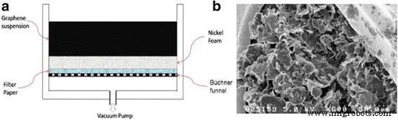
一 真空过滤法构建含石墨烯超级电容器电极的示意图。 b 通过真空过滤形成的镍泡沫上石墨烯/PVDF 的 SEM 图像。经许可转载自 [10]。版权所有 2012 爱思唯尔
石墨烯和 PTFE 超级电容器
PTFE也是一种常用的超级电容器聚合物粘合剂,它是另一种类似于PVDF的含氟聚合物。与 PVDF 不同的是,它的骨架上有更多的氟原子。另一个区别在于在水中的溶解度。 PVDF 通常为白色粉末形式,需要使用 NMP 等有机溶剂与活性材料(如活性炭、石墨烯和碳纳米管)混合。然而,聚四氟乙烯可以分散在水中(例如,聚四氟乙烯 60 重量%分散在水中)[11,12,13]、异丙醇 [14, 15] 和乙醇 [16,17,18]。由于此特性,活性炭超级电容器行业倾向于使用 PTFE,因为处理水溶剂的成本效率极高,更不用说使用有机溶剂的安全相关问题。
不同类型的粘合剂会导致超级电容器的不同性能。阿巴斯等人。发现对于活性炭 (AC),使用 NaNO3 水性电解质的超级电容器,相同数量 (10 wt%) 的不同粘合剂(PTFE 与 PVDF)会影响超级电容器的整体性能 [19]。发现带有 PVDF 粘合剂的电极比带有 PTFE 粘合剂的电极孔隙更少,如图 2a 中的孔径分布所示。因此,与 AC-PVDF 电极相比,AC-PTFE 电极具有更高的微孔体积(孔宽度 <5 nm),因此具有更高的电容,如图 2b [19] 所示。
<图片>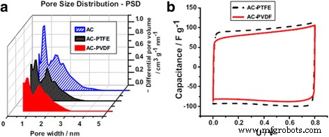
一 AC、AC-PTFE 和 AC-PVDF 电极的孔径分布。 b 循环伏安图 (2 mV · s −1 ) 1 mol · L -1 中高达 0.8 V 的 AC/AC 电容器 NaNO3 与 PTFE 和 PVDF 粘合剂。经[19]许可转载。版权所有 2014 爱思唯尔
聚四氟乙烯是绝缘和疏水的。过多的 PTFE 会降低电极的电导率并抑制含水电解质离子渗透到电极材料中的微孔中,导致能量密度和比电容降低 [20]。 PTFE 的最佳含量取决于多种因素,包括活性材料、电极材料和电解质等。Tsay 等人。据报道,对于使用 Na2SO4 溶液作为电解质的基于碳 BP2000 的超级电容器,在复合材料中使用 5wt% 的 PTFE 可实现最大的比电容和能量密度。 PTFE粘合剂不足会导致活性材料在电极上的粘附问题,并且比电容,尤其是长循环的电容保持率也会受到不利影响。在另一项研究中,朱等人。发现对于由交流电在镍泡沫和 6 M KOH 水性电解质上制成的超级电容器,使用 10% 的 PTFE 可实现最大比电容。然而,当使用PVDF粘合剂(5%)时,最佳条件有所不同[21]。
良好的润湿性可以使电解质离子更容易进入电极材料的多孔结构,从而实现更高的双电层电容。为了增加 PTFE 粘合剂对某些水性电解质的亲水性,可以将少量的聚乙烯吡咯烷酮 (PVP)(例如 3%)添加到 PTFE 分散体中 [22]。保罗等人。发现带有 PTFE 粘合剂的电极材料的接触角为 151°,这表明其具有超疏水性;但加入 3% PVP 后,接触角急剧下降至 22°,表明电极具有良好的润湿性 [23]。
根据所选择的电解质,基于石墨烯的超级电容器的行为会有所不同。斯托勒等人。使用化学改性的石墨烯作为活性材料,PTFE 作为粘合剂形成石墨烯基超级电容器,并在水性和有机电解质中对其进行测试 [24]。图 3 显示了使用 KOH、碳酸丙烯酯 (PC) 中的 TEABF4 和乙腈 (AN) 中的 TEABF4 作为不同电解质的石墨烯/PTFE 超级电容器的循环伏安法 (CV) 和奈奎斯特图的不同特性。发现水性电解质 KOH 提供了最高的比电容 116 Fg -1 与 100 Fg −1 相比 在 TEABF4/AN 和 95 Fg −1 在 TEABF4/PC [24] 中。还应该注意的是,超级电容器的等效串联电阻 (ESR) 在这三种电解质中是不同的,如奈奎斯特图所示。在设计超级电容器时,还应考虑电解液、活性材料和集流体的相容性。
<图片>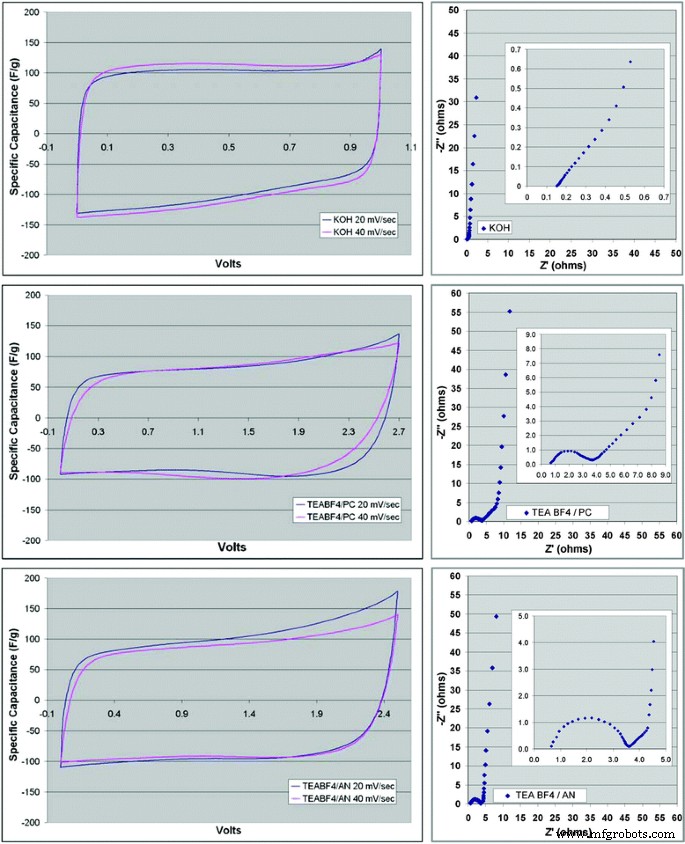
简历(左 ) 和 Nyquist (对 ) 带有 KOH 电解质的 CMG 材料图 (top ), 碳酸亚丙酯中的 TEABF4 (中 ) 和乙腈中的 TEABF4 (底部 )。经[24]许可转载。版权所有 2008 美国化学会
石墨烯和导电聚合物复合材料
如上所述,聚合物粘合剂是形成超级电容器电极的非常重要的部分。然而,使用聚合物粘合剂的一个缺点是它们通常不导电并且会降低超级电容器的能量密度。基于石墨烯/聚合物粘合剂复合材料的超级电容器主要基于双电层(EDL)电容。另一方面,导电聚合物 (CP) 提供了一种替代方法,并在超级电容器应用中引起了广泛关注。它们是导电的,并且可以与电解质发生非常快速的氧化还原反应,除了 EDL 电容之外,这还可以导致存储在超级电容器中的赝电容。 CP 具有 π 共轭骨架,由单 (C-C) 和双 (C =C) 碳键组成。在所有共轭 CP 中,聚(吡咯)(PPy)、聚苯胺(PANI)和聚(3,4-亚乙基二氧噻吩)(PEDOT)是超级电容器应用中三种最常用的 CP 类型,因为它们具有高导电性、易于合成、成本效益和重量轻 [25, 26]。这些聚合物的共轭骨架可以通过氧化进行 p 掺杂或通过还原进行 n 掺杂,分别形成 p 型 CP 或 n 型 CP。图 4 显示了 p 掺杂的 PPy 的化学结构。正电荷离域在PPy主链上,A − 代表抗衡阴离子,如 NO3 − , ClO4 − , Cl − 等
<图片>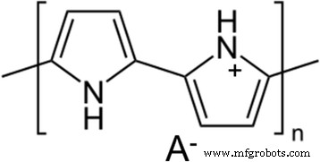
化学结构p掺杂PPy
尽管作为超级电容器电极,它们具有高导电性、快速充电和放电、高比电容 [27,28,29],但单独使用 CP 作为超级电容器电极的主要缺点是它们在长循环中存在稳定性问题。在长时间循环的氧化还原反应过程中,由于 CP 的体积变化引起的机械应力会导致 CP 的裂纹、材料损失甚至断裂。随着时间的推移,这些故障最终会导致超级电容器设备的容量下降甚至损坏。延长基于 CP 的超级电容器寿命的一种解决方案是将 CP 与多种形式的碳(例如 AC、CNT 和石墨烯)复合。这些复合材料表现出更好的稳定性,因为复合材料中的碳网络可以调节充电和放电循环期间的体积变化,因此循环期间的电容保持率可以大大提高 [30,31,32]。一般来说,p 掺杂的 CP 比 n 掺杂的更稳定 [33, 34]。本次会议将主要关注p掺杂CPs与石墨烯及其衍生物在超级电容器应用中的复合材料。
石墨烯和聚苯胺 (PANI) 复合材料
由于其高导电性、电活性、比电容和良好的稳定性,PANI 作为超级电容器电极材料被广泛研究。 PANI 需要一个质子才能导电并正确充电和放电;因此,PANI 需要质子溶剂、酸性溶液或质子离子液体才能用于超级电容器应用 [35, 36]。 PANI 最常见的合成方法是氧化聚合和电化学聚合。其他方法也可用于生产纳米结构的 PANI(例如,纳米纤维和纳米粒子),例如界面聚合 [37]、静电纺丝 [38]、种子聚合 [39]、模板聚合 [40] 等。 应注意每种方法合成的聚苯胺聚合物往往具有不同的性质,因此得到的聚苯胺基超级电容器可以表现出相当不同的性能。
PANI 和石墨烯的复合材料可以通过苯胺与石墨烯悬浮液在酸性溶液中的原位聚合来制备。张等人。使用氧化石墨烯 (GO) 与 PANI 混合形成复合材料并滴铸到玻璃碳工作电极上进行电化学表征 [41]。在研究中,GO 是由石墨通过改进的 Hummers 方法制备的,具有几十微米大小的层状结构。 [41] 中使用氧化聚合方法在 1 M HCl 酸性介质中合成 PANI 纳米纤维,同时使用过二硫酸铵 ((NH4)2S2O8) 作为氧化剂。如图 5 所示,GO/PANI 复合材料中不同的 GO 浓度导致不同的复合形态,影响作为超级电容器电极的电化学行为 [41]。纯 PANI 纳米纤维在 CV 曲线中有一对氧化还原峰,但 GO/PANI 复合材料表现出纯 GO 和纯 PANI 的两种特性,显示出两对氧化还原峰。纯 PANI 纳米纤维 (PANI-F) 电极具有非常高的比电容,为 420 Fg −1 然而,循环稳定性较差,仅 5 个循环后比电容就降低了近 40%。随着 GO 浓度的增加,复合材料的比电容降低 (PAGO10:320 Fg −1 , PAGO50:207 Fg −1 , 和 PAGO80:158 Fg −1 )。另一方面,随着复合材料中GO浓度的增加,长循环的电容保持率大大提高,因为GO纳米颗粒可以补偿充放电循环过程中PANI的体积变化。
<图片>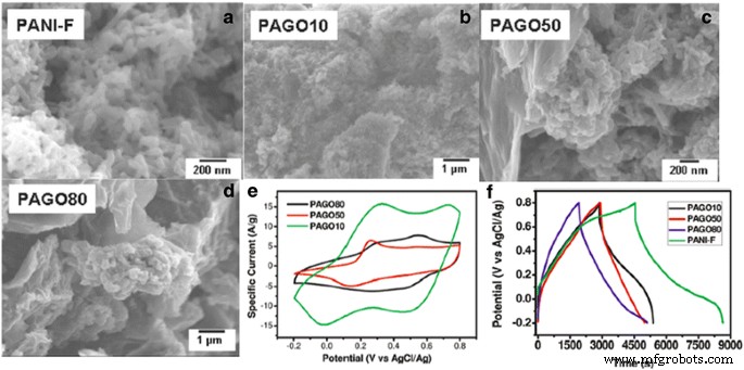
一 纯PANI纤维(PANI-F)的SEM。 b GO 和 PANI 复合材料的 SEM,GO 重量百分比为 10% (PAGO 10)。 c GO 和 PANI 复合材料的 SEM,GO 重量百分比为 50% (PAGO 50)。 d GO 和 PANI 复合材料的 SEM,GO 重量百分比为 80% (PAGO 80)。 e 使用涂有玻璃碳电极的不同复合材料作为工作电极、Pt 片作为对电极和 AgCl/Ag 电极作为参比电极在 2 M H2SO4 中记录的循环伏安图。扫描速率为 100 mV/s; f 不同复合电极在 0.1 A/g 电流密度下的充放电循环曲线。经[41]许可转载。版权所有 2010 美国化学会
GO 本质上是绝缘的,复合材料中的 GO 纳米颗粒对比电容的贡献很小。复合材料的总电容主要来自PANI纳米纤维的赝电容。许多研究 [42, 43] 开始使用还原氧化石墨烯 (RGO) 来代替 GO,因为 RGO 具有更高的比电容,并且由于其更高的电导率还可以降低超级电容器电极的 ESR。基于化学、热或电化学方法,可以通过还原 GO 纳米粒子来制备 RGO 纳米粒子。王等人。使用三步合成方法通过原位聚合-还原/去掺杂-重掺杂工艺形成 RGO 和 PANI 复合材料 [44]。这种原位工艺能够促进 RGO 均匀分散到复合材料中,其示意图如图 6a 所示:(i)乙二醇中的 GO 被超声处理以获得均匀的剥离氧化石墨烯悬浮液(GEO); (ii) 在搅拌下向混合物中加入苯胺溶液; (iii) 加入盐酸(HCl)和过硫酸铵(APS)聚合形成GO和PANI复合材料(GEOP-1); (iv) 然后将 90°C 的氢氧化钠 (NaOH) 添加到悬浮液中以还原 GO 并同时对 PANI 聚合进行去掺杂以形成 RGO 和去掺杂的 PANI 复合材料 (GEP-2); (v) 最后,重新引入 HCl 以重新掺杂 PANI 以形成 RGO 和重新掺杂的 PANI 复合材料 (GEP-3) [44]。 RGO 和 PANI 复合材料的厚度为 30-40 纳米,尺寸为几微米,这表明这些纳米复合材料的比表面积很大。从图 6b、c 还可以看出,将 GO 还原为 RGO,会导致 PANI/RGO 电极的氧化还原峰更高,从而导致更高的比电容。本研究中最高的比电容是 GEP-2,具有 1129 Fg -1 .与 GO/PANI 复合材料类似,与纯 PANI 电极相比,RGO/PANI 超级电容器电极的循环保留率也有所提高:GEP-2 和 GEP-3 在 1000 次循环后的电容保留率分别为 84% 和 72%。
<图片>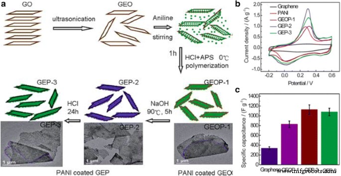
一 图解说明石墨烯/PANI 杂化材料的制备过程。 b 石墨烯、PANI、GEOP-1、GEP-2 和 GEP-3 的 CV 曲线,在 1 mV s −1 在 1 M H2SO4 中,电位范围为 -0.2 至 0.6 V。c 比电容随样品不同而变化。经[44]许可转载。版权所有 2010 英国皇家化学会
石墨烯和聚吡咯 (PPy) 复合材料
Weiss 等人首先证明了 PPy。 1963 年 [45]。 PPy 也是一种非常吸引超级电容器应用的 CP 材料,因为这种聚合物的合成很简单,并且具有良好的导电性和热稳定性。与 PANI 相比,纯 PPy 聚合物具有非常不同的形态,如图 7 所示 [46]。薄(图 7a)和厚(图 7c)PANI 膜均由纳米原纤维组成。然而,PPy 薄膜(图 7b)包含亚微米颗粒,随后随着聚合电荷的增加形成聚集的花椰菜状结构(图 7d)以增加薄膜厚度。厚 PPy 膜的这种聚集结构不利于超级电容器应用,因为它们使表面积最小化并有阻止电解质离子进入的趋势。此外,在充放电循环过程中,由于体积变化引起的应力,这些颗粒结构很容易坍塌。一般来说,与PANI薄膜相比,纯PPy薄膜作为超级电容器的循环性能较差[46]。
<图片>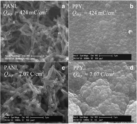
在低 (424 mC/cm 2 ) 和高 (7.07 C/cm 2 ) 所示的沉积电荷 (Qdep)。经[46] 许可转载。版权所有 2007 Elsevier
与 PANI/石墨烯纳米复合材料类似,PPy 在石墨烯存在下的原位聚合也是优选的。通过这样做,它可以更好地分散石墨烯纳米粒子并最大限度地减少聚集。博斯等人。在聚(4-苯乙烯磺酸钠)(Na-PSS)存在下还原GO来修饰石墨烯的表面,以避免石墨烯纳米片(GNS)的聚集[47]。 GNS 的厚度约为 2 纳米,可能是双层或多层单石墨烯片。将表面改性的 GNS 和吡咯单体在乙烯溶液中混合后,向混合物中加入氯化铁 (FeCl3) 开始聚合,形成 GNS/PPy 复合材料。 GNS/PPy 复合材料的成功混合可以通过检查拉曼光谱中纯 GNS 和 PPy 两个峰的存在来表示。在 [47] 中,已经观察到,与纯 PPy 薄膜相比,GNS/PPy 复合材料的比电容几乎是超级电容器电极的两倍,并且循环性能要好得多。这些结果再次证明,石墨烯掺入PPy可以促进PPy的电化学利用,并为PPy提供机械支撑以提高复合材料在充放电循环过程中的结构稳定性。
石墨烯和聚(3,4-乙撑二氧噻吩)(PEDOT)复合材料
聚(3,4-亚乙基二氧噻吩)(PEDOT)于 1980 年代首次由德国拜耳股份公司研究实验室的科学家开发 [48]。 PEDOT 可以使用标准的氧化化学或电化学聚合方法制备,它在掺杂状态下具有非常高的电导率,从几到 500 S/cm [49, 50]。 PEDOT 最初被发现是不溶性的,但后来通过使用水溶性聚电解质聚(苯乙烯磺酸)(PSS)[51] 避免了这种溶解性问题。 PEDOT还具有广阔的潜力窗口、良好的热稳定性和化学稳定性,引起了超级电容器界的广泛关注。与其他导电聚合物相比,PEDOT 具有出色的循环稳定性,在 70,000 次循环中具有 80% 的电容保持率 [52]。然而,PEDOT作为超级电容器的一个缺点是分子量大,导致比电容相对较低[36]。
为了最大限度地减少复合材料中石墨烯纳米颗粒的聚集,可以使用类似的原位聚合方法来形成石墨烯/PEDOT 复合材料。首先,将 PSS 和乙烯二氧噻吩 (EDOT) 单体混合在 HCl [53]、去离子水 [54, 55] 等水溶液中,有时在将石墨烯或石墨烯衍生物纳米粒子分散到其中之前进行脱气过程 [55, 56]搅拌或超声处理得到的溶液。接下来,氧化剂如过硫酸铵 [(NH4)2S2O8] 和氯化铁 (III) (FeCl3) [53],或过硫酸钠 (Na2S2O8) 和硫酸铁 (III) [Fe2(SO4)3] [56] 是然后加入以引发聚合反应,最终形成石墨烯/PEDOT 复合材料。图 8 显示了 RGO 和 RGO/PEDOT 复合材料的 SEM 图像比较 [57]。原始 RGO 薄膜相对较大且光滑,而 RGO/PEDOT 复合薄膜形成了约 200 nm 厚的弯曲平面薄膜 [57]。据报道,随着石墨烯的加入,石墨烯/PEDOT 的电导率比原始 PEDOT 提高了两倍以上,同时机械强度也提高了六倍[58]。石墨烯在复合材料中的作用是为电荷渗透和传播提供途径,从而改善PEDOT的整体电荷传输行为[59]。
<图片>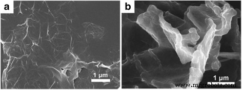
(a 的 SEM 图像 ) 纯 RGO 薄膜 (b ) RGO 和 PEDOT 复合薄膜。经[57]许可转载。版权所有 2013 英国皇家化学会
原始 PEDOT 超级电容器的比电容范围为 70 至 130 Fg −1 [52, 60, 61] 取决于不同的聚合方法。然而,使用基于石墨烯/PEDOT 复合材料的超级电容器已经观察到增强的比电容和循环稳定性性能。例如,阿尔维等人。报道了基于石墨烯/PEDOT 的超级电容器,其比电容为 304 和 261 Fg −1 分别在 HCl 和 H2SO4 电解质中 [53]。文等人。据报道,GO/PEDOT 复合电极的比电容为 136 Fg -1 ,RGO/PEDOT复合电极的比电容为209 Fg −1 在 2000 次循环中具有 87% 的电容保持率 [62]。石墨烯在复合材料中作为超级电容器的作用是(i)它与 PEDOT 形成异质结构,有效减少因体积变化(即溶胀、和收缩)PEDOT 在充放电循环期间,(ii)石墨烯或 RGO 具有比 PEDOT 更高的导电性:PSS,使复合材料更具导电性,以及(iii)石墨烯的添加使复合材料具有 3D 形态,可以导致通过为电解质渗透和氧化还原反应提供大表面积来显着提高比电容[60]。
石墨烯和导电聚合物 (CP) 复合材料比较和总结
石墨烯及其衍生物在制成复合材料时对CPs的形貌、电学性能和结构稳定性有很大影响,从而导致CPs电化学性能的显着提高。 However, for a graphene/CPs supercapacitor, there are many factors which can determine the ultimate supercapacitor performance (i.e., specific capacitance, cycling stability, charge-discharge properties, etc.) such as polymerization method, intrinsic properties of individual CPs, electrolyte, dispersion/aggregation of the graphene in the composites, different properties of graphene used, etc. Generally speaking, for the aforementioned three types of CPs (PANI, PPy, and PEDOT), there are distinct advantages and disadvantages of using individual CPs to form the composite. PEDOT has the largest molecular molar mass, hence, the specific capacitance of the graphene/PEDOT composites supercapacitor is normally smaller than the ones formed with PANI or PPy. On the other hand, the larger particles formed in the PPy film make it less porous than PANI or PEDOT, thus the cycling performance of PPy is normally the worst among these three CPs. In addition, the conductivity comparison of these CPs is PEDOT > PPy > PANI [63], which can affect the ESR of the supercapacitors.
张等人。 compared the supercapacitor performance of the composites formed of RGO nanosheets with PANI, PPy, and PEDOT polymers using similar polymerization and mixing methods [42]. The specific capacitances of the supercapacitor electrodes from RGO/PANI, RGO/PPy, and RGO/PEDOT composites are 361, 249, and 108 Fg −1 at the current density of 0.3 Ag −1 , respectively. Figure 9a–c shows the different cyclic voltammograms (CV) of the RGO and CPs composite electrodes at different scan rates [42]. The quasi-rectangular CV curves of both RGO-PEDOT and RGO-PPy suggest good capacitive behaviors of both supercapacitor electrodes. The redox peaks in the range of +0.3 to 0 V on the RGO/PANI CV curves are due to the redox transition of PANI between the semiconducting state form and the conductive form [42, 64, 65]. Figure 9d shows the cycle stability of PANI fibers, RGO-PANI, RGO-PEDOT, and RGO-PPy during the long-term charge/discharge process [42]. With the RGO addition, all the composite supercapacitor electrodes showed good cycling performance compared to pristine PANI fibers with capacitance retention of only 68% after 600 cycles. However, RGO/PEDOT has the best capacitance retention of 88% after 1000 cycles, while RGO/PANI and RGO/PPy have the similar cycling performance of 82 and 81% retention after 1000 cycles [42].

Cyclic voltammograms of (a ) RGO-PEDOT (b ) RGO-PPy, and c RGO-PANi cycle stability of PANi fibers, RGO-PANi, RGO-PEDOT, and (d ) RGO-PPy during the long-term charge/discharge process. Reprinted with permission from [42]. Copyright 2012 American Chemical Society
Table 1 summarizes the recent development of graphene and CP (PANI, PPy, and PEDOT) composites in supercapacitor applications. Ragone plot comparing the power density and energy density of the graphene and CP composites supercapacitors in the summarized references is shown in Fig. 10. It should be noted that most studies reported specific capacitance of supercapacitor electrode based on three-electrode system (i.e., working, counter, and reference electrodes). Symmetric supercapacitor cells composed of anode and cathode of the same materials normally have less than half the specific capacitance of single electrode considering the separator and electrolyte weight. In addition, it is not surprising that very high specific capacitances in some studies were reported since only a small amount of active materials were applied/coated on the working electrode for electrochemical characterization. For practical purposes, it is hard to achieve the same level of specific capacitance since it may not increase linearly with increasing amount of materials.

Ragone plot of graphene and CP composites supercapacitors in the summarized references listed in Table 1
Graphene and Polymer Composites for Flexible Supercapacitor Applications
The recently developed flexible electronic devices such as flexible displays, curved smartphones, flexible implantable medical devices, and wearable electronic devices imply that flexible devices are beginning to emerge as the leading revolution in next generation of electronics. Several advantages of flexible electronic devices compared to conventional electronic devices include lighter weight, wearability, bendability, environmental friendliness, reduced cost, etc. In order to match the fast growth of flexible electronic devices, energy storage systems that are light, thin, and flexible should also be developed. Recently, considerable attempts have been made to develop flexible supercapacitor electrode based on carbon materials including activated carbon [7, 66], carbon nanofibers [67, 68], carbon nanotubes [69,70,71], and graphene [72,73,74,75]. Graphene film can be prepared ultrathin (<100 nm) by filtration method and transferred to a flexible polyethylene terephthalate (PET) substrate to make flexible supercapacitor electrodes as Fig. 11 shows [76]. Although the PET substrate is flexible and can provide mechanical support to the graphene film, it does not provide any capacitance as supercapacitors, thus the device capacity would be affected by introducing the additional PET substrate. In addition, there are issues associated with the transferring process, and it is hardly a scalable process as wrinkles or other defects can happen during the graphene transfer process. Furthermore, the restacking of graphene can cause the decrease of the surface area which leads to a relatively specific capacitance of 100 Fg -1 for the 100-nm-thick graphene film. There are other types of flexible supercapacitor electrodes based on graphene materials, such as graphene paper [77, 78], graphene foam [79, 80], and graphene on carbon cloth/fabric [7, 81,82,83]. However, in each case, there may exist issues in graphene restacking, yield, limited power density and energy density, cost, and scalability. Similar to existing activated carbon supercapacitor industry, roll-to-roll manufacturing compatibility is an ideal feature for the flexible supercapacitor materials.

一 Photographs of transparent thin-films of varying thickness on glass slides. b TEM image of graphene collected from dispersion before filtration. c SEM image of 100 nm graphene film on glass slide. Reprinted with permission from [76]. Copyright 2012 AIP Publishing LLC
Graphene/conducting polymers (CPs) composite film, due to its flexible nature, becomes a viable option for flexible supercapacitor applications as it can also adapt to the roll-to-roll manufacture. Graphene/CPs film can be assembled with solid electrolyte to form a flexible supercapacitor device which can be subject to high degrees of bending or twisting without losing the device integrity. Meanwhile, as it is discussed previously, CP itself can provide pseudocapacitance due to the redox reaction, increasing the specific capacitance, as well as the capacity of the device. Figure 12 shows the schematics of a typical assembly process of a flexible supercapacitor using RGO-PEDOT/PSS film [84]. The PVDF substrate used in the coating process was later peeled off, which is a good way to eliminate the unnecessary weight and volume of the whole supercapacitor device. Poly(vinyl alcohol) (PVA)/H3PO4 gel was used as the solid electrolyte in this device, and gold was sputter coated on one side of the electrode as the metal current collector [84]. Polymer gel electrolyte can be used as both a porous separator and electrolyte reservoir because of its microchannels or pores inside the structure, which facilitate the flow of electrolyte ions and avoid electrical shorting between the electrodes. Furthermore, the semi-solid framework of gel electrolyte provides good adhesion with minimal distance between the electrode/electrolyte/electrode interfaces, and thus efficiently enhances the charge-storage mechanism [85].

Schematic illustration of the preparation process of rGO-PEDOT/PSS films and the structure of assembled supercapacitor devices. Reprinted with permission from [84]. Copyright 2015 Nature Publishing Group
Bending test is usually necessary to examine the structural and electrical integrity of the flexible supercapacitor device subject to different bending angles and cycles. Bending or twisting can cause stress on the films which may lead to material loss, material fatigue (e.g., crack) or even material failure (e.g., fracture). CV and/or charge-discharge curves are monitored at several of bending angles during the bending cycles [84, 86,87,88,89,90] to test the device integrity. Graphene, due to its excellent mechanical strength, can prevent the flexible device from being ruptured by the repeatedly applied loads during the bending/twisting test, and it becomes an important part in the fabrication of the flexible electrode. Figure 13 shows the CV and specific capacitance of RGO-PEDOT/PSS flexible supercapacitor during the bending test [84], and it should be noted from Fig. 13b that there is no significant change of CV curves after 1000 bending cycles with a large bending angle (at 180 °). Figure 13c suggests that the specific capacitance of device in the 180 °bended state is only 5% smaller compared to the one under flat state after 10000 charge and discharge cycles. The flexible supercapacitor device made from a long strip of electrodes (15 × 2 cm) that have been rolled up as shown in Fig. 13d, e) was powerful enough to power a light-emitting diode for 20 s when fully charged (Fig. 13f) [84].

一 CVs of rGO-PEDOT/PSS during bending. Scan rate = 50 mV s −1 . b CVs of rGO-PEDOT/PSS after being subject to bending. c Long-term test of rGO-PEDOT/PSS under flat or 180 ° bended states at a current density of 1 A g −1 . d Flexible films coated with solid electrolyte spread out on an Au-coated membrane, e rolled design, and f the resulting device used to power a green light-emitting diode (LED). Reprinted with permission from [84]. Copyright 2015 Nature Publishing Group
Conclusions
The emergence of graphene has undoubtedly changed the scope of supercapacitor field due to its outstanding electrochemical properties along with other unique properties such as large surface area, high electrical conductivity, light weight, and mechanical strength. The recent development of graphene and polymer composites showed very promising features of these composite materials for supercapacitor applications. Compounded with binder polymers, graphene would compensate the undesired features of insulating polymers (e.g., insulating nature, low surface area, and low specific capacitance). On the other hand, when graphene makes composites with conducting polymers, it would provide mechanical support for the framework of the polymers and thus greatly improve the cycling performance as well as the specific capacitance. In addition, the flexible nature of the graphene/polymer film makes it possible for flexible, wearable, conformable energy storage devices. Despite the innovative ideas and techniques that have been demonstrated for the graphene/polymer supercapacitor device with unique features not possessed by current state-of-art technology, there remain a lot of challenges for graphene/polymer composite-based supercapacitors to reach their full potentials. One of the main challenges is to find a feasible way for the low-cost mass production of graphene/polymer supercapacitor electrode without compromising the micro/nanostructures of graphene due to the restacking or aggregation. Many studies have demonstrated the compatibility of large-scale coating or roll-to-roll manufacture capability of graphene/polymer supercapacitor electrodes, however, there is still a need to have a rational design of the porous structures inside the supercapacitor electrodes to form hierarchical interconnected porous microstructures and avoid the formation of dead volume or the collapse of the porous microstructures [91]. Furthermore, in most studies related to graphene/polymer-based supercapacitors, the mass specific capacitance of the supercapacitor electrode is often emphasized as one of the most important features. However, these values are often derived from the weight of a small amount of active material applied on the working electrode. In practical supercapacitor devices, to obtain a reasonable value of the device capacity, thicker coating or larger amount of material are often needed. It should be noted that the electrode total capacitance does not increase linearly with increasing amount of materials. In addition, one should also take into consideration the weight of current collector, electrolyte, and separator for supercapacitor device perspective. These aspects should be all considered to develop a deeper understanding of storage mechanism, interfacial relation, and designs of graphene/polymer-based supercapacitors. Last but not the least, integration of graphene/polymer supercapacitors with other electronic devices (e.g., solar cells, batteries) remains a challenge for practical applications. In conclusions, graphene/polymer composites have great potential for supercapacitor applications to improve current activated carbon-based supercapacitors, and we believe graphene/polymer-based supercapacitor would find its place in commercialization in the near future.
纳米材料
- 传感器和处理器融合用于工业应用
- 用于改进诊断和治疗应用的多功能金纳米粒子:综述
- 用于合成和生物医学应用的荧光纳米材料的进展和挑战
- S、N 共掺杂石墨烯量子点/TiO2 复合材料用于高效光催化制氢
- 具有分层多孔结构的单分散碳纳米球作为超级电容器的电极材料
- 碳纳米纤维和活性炭作为水性电解质中对称超级电容器的研究:一项比较研究
- 石墨烯/WO3 和石墨烯/CeO x 结构作为超级电容器应用电极的评估
- 纳米级 CL-20/氧化石墨烯的一步球磨制备显着降低粒径和灵敏度
- 聚苯胺/氮掺杂有序介孔碳复合材料的合成和超级电容器性能
- 还原氧化石墨烯/碳纳米管复合材料作为电化学储能电极的应用
- 金纳米团簇的生物医学应用:最新发展和未来展望
- 工业制冷和工业冷却应用驱动器