

炉内燃料燃烧和传热
熔炉中的燃料燃烧和传热
炉中需要热量来加热炉料(要在炉中加热的材料),有时也需要加热化学反应。三种热能来源是(i)燃料燃烧,(ii)电能,和(iii)通过放热反应可获得的化学能。除了电热炉,这种热量(不包括化学能)的需求是通过燃料的燃烧来满足的。燃料可以是气体燃料(例如焦炉煤气、高炉煤气、转炉煤气、天然气、液化石油气等副产气体)、液体燃料(例如燃料油、焦油等)。 ,或固体燃料(如煤、焦炭等)。
所有燃料都含有势能。在燃烧时,这种势能在燃烧产物 (POC) 中释放。燃烧通常被认为是燃料和氧化剂之间的化学反应中热量和能量的受控释放。工业过程中几乎所有的燃烧都使用碳氢化合物燃料。典型碳氢燃料的一般燃烧反应由方程式燃料 + 氧化剂 =二氧化碳 (CO2) + 水蒸气 (H2O) + 其他物质给出。 “其他种类”取决于所用氧化剂的类型以及燃料与氧化剂的比例。最常用的氧化剂是空气,它由按体积计近 79% 的氮气 (N2) 组成,通常在燃烧过程中通过。如果燃烧是富含燃料的,这意味着没有足够的氧气 (O2) 来完全燃烧燃料,那么废气中就会存在未燃烧的碳氢化合物,并且很少(如果有的话)过量的 O2。如果燃烧是贫燃料,这意味着氧气比完全燃烧燃料所需的氧气多,那么废气中的氧气就会过多。
燃料对炉膛燃烧系统中的传热有显着影响。最重要的特性之一是燃料的热值。这用于确定要燃烧多少燃料来处理被加热材料的所需生产率。热值指定为高热值(HHV)或低热值(LHV)。
LHV 不包括汽化热,汽化热是将液态水转化为蒸汽所需的能量。这意味着 LHV 假设所有 POC 都是气态的,这通常是几乎所有工业燃烧应用的情况。如果燃烧产物要在足够低的温度下离开过程,以使所有的水都从气体转化为液体,那么冷凝热将作为额外的能源释放到过程中。燃料的 HHV 包括这种额外的能量。
燃料的成分对于确定 POC 的成分和燃烧燃料所需的氧化剂量很重要。需要燃料的密度来确定通过熔炉的燃料输送系统的流量以及相关的管道尺寸。
废气成分对于确定炉内的热传递非常重要。排气中未燃烧的碳氢化合物表明燃料没有完全燃烧,因此所有可用的热量都没有释放出来。废气中的高过量 O2 水平通常表明提供了过多的氧化剂。过量的氧化剂通过废气将显能带出。这再次意味着燃料的一些可用热量尚未完全用于加热炉料。如果氧化剂是空气,那么燃料中的大部分可用能量随着废气产物在烟道中进行。
POC 将热能传递给炉料,使其温度升至所需值,然后离开炉子。在临界工艺温度下,POC 中的显热不适用于熔炉。过程临界温度越高,POC 中的显热越高。从燃料利用的角度来看,POC中的这种显热非常重要。
工业燃烧过程中使用了两种常见类型的氧化剂。大多数过程使用空气作为氧化剂。然而,许多高温工艺使用的氧化剂含有比空气中更高浓度的 O2(约 21% 体积)。这种类型的燃烧称为 O2 增强燃烧。在许多情况下,加热过程中的产率可以显着提高,只需相对少量的富氧。
在一些情况下,空气/燃料燃烧器可以成功地使用含有高达 30% 左右 O2 的氧化剂,只需很少或无需修改。在较高的 O2 浓度下,火焰会变得不稳定或火焰温度会变得太高,以至于燃烧器设计为在空气/燃料条件下运行。在更高温度的应用中,更高纯度 O2 的好处证明额外成本是合理的,可以使用更高纯度的氧化剂(大于 90 % O2)。高纯度 O2 极大地加强了加热过程。氧化剂纯度对燃烧系统的传热有重要影响。
燃烧系统的一个重要方面是燃料与氧化剂的比例。有很多方法可以指定这一点。简而言之,这些都是经过深思熟虑的。使用 CH4(甲烷)作为燃料的全局燃烧反应可以写为 CH4 + (xO2 + yN2) =CO、CO2、H2、H2O、N2、NOx、O2、痕量组分。反应的化学计量表示给定燃烧系统的 O2 与燃料的比率。量化化学计量的一种方法是仅考虑氧化剂中的 O2,因为反应不需要氧化剂中的惰性物质。因此,将 CH4 视为燃料,与空气的整体简化化学计量反应可写为 CH4 + (2O2 + 7.52N2) =CO2 + 2H2O + 7.52N2。在这个反应中,空气表示为 2O2 + 7.52N2。这里化学计量比为 2,因为燃烧 1 分子 CH4 需要 2 分子 O2。
这种指定化学计量比的方法通常用于包含 O2 富集的燃烧系统。这是因为供给燃烧系统的氧气量很重要。
实际火焰通常需要一些过量的氧气才能完全燃烧燃料。这是由于燃料和氧化剂之间的不完全混合。对于 CH4 的富燃料燃烧,化学计量比小于 2。在 CH4 的稀燃料燃烧的情况下,化学计量比大于 2。因此,氧化剂成分很重要。确定氧化剂成分的常用方法是计算氧化剂中的 O2 摩尔分数。
许多工业燃烧过程运行的 O2 比理论上完美燃烧所需的 O2 高约 3%。这通常是最大限度减少未燃烧碳氢化合物排放并确保燃料完全燃烧所需的过量氧气量。这可能是由于燃料和氧化剂之间的混合限制,尤其是在非预混系统中。
过多的 O2 意味着能量被浪费在加热过量的燃烧空气上,而不是炉料的加热上。因此,希望仅使用足够过量的 O2 来获得低 CO(一氧化碳)排放。 CH4 与 3% 过量 O2 的简化全局反应示例是反应 CH4 + (2.06O2 + 7.75N2) =CO2 + 2H2O + 0.06O2 + 7.75N2。
大多数工业火焰是湍流的,通常由湍流雷诺数 (Re) 确定。湍流特征长度尺度通常称为 Kolmogorov 长度。 Kolmogorov 长度代表发生耗散的维度。泰勒长度尺度可以定义为应变率与粘性力的比值。各种长度可用于表征火焰。火焰可以是 (i) 起皱的火焰,(ii) 严重起皱的火焰,(iii) 涡流中的小火焰,和 (iv) 分布式反应前沿。无量纲的 Damköhler 数 (Da) 表示反应时间的类型,这对于特定类型的燃烧反应很重要。这个数字是反应时间与流速的比值。
燃烧特性
工业应用中通常使用的正常燃烧特性是 (i) 燃烧产物组成、(ii) 火焰温度、(iii) 可用热量和 (iv) 燃烧后的烟气体积。这些对于计算火焰的传热很重要并将废气排放到炉子和炉料中。
燃烧产物
有许多变量会对燃烧产物产生重大影响。一些重要的变量包括氧化剂成分、混合比、空气和燃料的预热温度以及燃料成分。下面简要讨论这些。
氧化剂成分 – 以 CH4 燃烧为例,CH4 与空气的化学计量燃烧可以用全局方程 CH4 + 2O2 + 7.52N2 =CO2、2H2O、7.52N2 和微量组分来表示。可以看出,超过 70 体积百分比的废气是 N2。类似地,化学计量的 O2/CH4 燃烧过程可以用方程式 CH4 + 2O2 =CO2、2H2O 和痕量物质表示。通过消除 N2,废气量大大减少。一般情况下,化学计量的O2增强CH4燃烧过程可以表示为CH4 + 2O2 + xN2 =CO2 + 2H2O + xN2 + 痕量组分。
燃烧反应产生的废气的实际成分取决于几个因素,包括氧化剂成分、气体温度和当量比。当量比定义为实际燃料/空气比与化学计量燃料/空气比的比率。当反应中所有的 O2 都被消耗掉并且产物中没有分子 O2 时,就会发生化学计量燃烧。
绝热过程意味着在反应过程中没有热量损失,或者反应发生在完全绝缘的室内。在实际的燃烧过程中,热量通过辐射从火焰中损失掉,情况并非如此。 CH4绝热平衡燃烧的预测主要产物是氧化剂组成的函数。
平衡过程意味着发生化学反应的时间是无限的,或者反应产物不受化学动力学的限制。然而,在实际条件下,燃烧反应在几分之一秒内完成。此外,随着从氧化剂中去除N2,废气中N2的浓度相应降低。同样,CO、CO2 和 H2O 的浓度也会增加。对于这种绝热过程,氧化剂中 O2 含量较高时会产生大量 CO。
自由基产物 H、O 和 OH 都随着氧化剂中的 O2 而增加。随着更多的 N2 从系统中去除,NO(一氧化氮)最初会增加,然后在氧化剂中约 60% O2 后减少。当氧化剂是纯 O2 时,由于没有 N2 可用,因此不会形成 NO。 H 2 形式的未燃烧燃料和O 2 形式的未反应氧化剂也随着氧化剂中的O 2 浓度而增加。这种自由基浓度的增加、CO和H2形式的未燃烧燃料以及未反应的O2都是由于在高温下发生的化学离解造成的。
由于火焰的不完全燃烧和辐射,实际火焰温度低于绝热平衡火焰温度。实际火焰温度取决于火焰辐射热量的程度以及燃烧系统(包括炉料和耐火墙)吸收热量的程度。
高度发光的火焰通常比高度不发光的火焰具有更低的火焰温度。当炉料和炉壁更具辐射吸收性时,实际火焰温度也较低。当炉料和炉壁温度较低且辐射吸收率较高时,就会发生这种情况。
当气体燃烧产物离开火焰时,它们通常会在穿过燃烧室时通过对流和辐射损失更多热量。燃烧过程的目的是将燃料中所含的化学能传递给炉料,或者在某些情况下传递给燃烧室。燃烧过程的热效率越高,从燃烧产物传递到炉料和燃烧室的热量就越多。因此,在热效率加热过程中,排气烟囱中的气体温度理想地远低于火焰中的温度。燃烧产物的组成随燃气温度的变化而变化。
混合比例 – 废气中的 O2 和 N2 浓度随着当量比严格降低。 H2O 和 CO2 浓度在化学计量条件下达到峰值。这很重要,因为这两种气体都会产生不发光的气体辐射。 H2 和 CO 形式的未燃烧燃料均随着当量比的增加而增加。这会反映在可用热量中,因为并非所有燃料都已完全燃烧。
空气和燃料预热温度 – 在许多工业燃烧过程中,热量被回收以提高过程的整体热效率,从而降低运营成本。回收的热量通常用于预热进入的燃烧空气,有时也用于预热进入的燃料。预热空气或燃料会影响燃烧产物的组成。由于化学分解,CO2、H2O 和 N2 在废气中随空气预热而减少。出于安全考虑和燃料供应管道的烟灰可能性,在大多数情况下,较高的燃料预热温度是不切实际的或不推荐的。通常可以看出,废气中主要成分的浓度仅略有下降,而次要成分的浓度略有增加。这是因为燃料的质量与供应给燃烧系统的燃烧空气的质量相比相对较小。这意味着在给定的预热温度下,预热燃烧空气比预热燃料具有更显着的影响。
燃料成分 – 燃烧产物取决于燃料成分。可以计算在各种操作条件下不同燃料的预测燃烧产物成分。最常用的气体燃料是 H2(氢气)、CH4、C3H8(丙烷)以及 H2 和 CH4 的混合物。这些旨在代表工业应用中通常使用的燃料。就光度而言,H2产生不发光火焰,CH4产生低光度火焰,C3H8产生较高光度火焰。
火焰温度 – 火焰温度是决定从火焰到炉料的热传递的关键变量。绝热火焰温度受氧化剂和燃料成分、混合比以及空气和燃料预热温度的影响。但实际火焰温度不如绝热火焰温度高,但趋势具有可比性和代表性。
氧化剂和燃料成分 – 当空气被 O2 替代时,火焰温度会显着升高,因为 N2 作为稀释剂会降低火焰温度。对于空气和纯 O2,火焰温度通常会有所不同。火焰温度从空气迅速上升到氧化剂中约 60% 的氧气。对于较高的 O2 浓度,火焰温度以较慢的速度增加。此外,燃料成分对火焰温度有很大影响。在 H2 和 CH4 的燃料混合物中,温度随着混合物中 H2 含量的增加而增加。值得注意的是,这种增加不是线性的,在 H2 水平越高时增加越快。由于与 CH4 和 C3H8 相比,H2 的成本相对较高,因此在许多工业应用中并未使用它。然而,在许多碳氢化合物应用中经常使用高 H2 燃料。这些燃料是化学制造过程的副产品,因此比从工业气体供应商处购买 H2 便宜得多,并且比使用其他购买的燃料更具成本效益。
混合比例 – 峰值火焰温度出现在化学计量条件下。氧化剂中的 O2 浓度越低,在非化学计量条件下(富油或贫油)运行时火焰温度降低得越多。这是由于较高浓度的 N2 吸收热量并降低了整体温度。在化学计量条件下,只有足够的氧化剂来完全燃烧所有燃料。任何额外的氧化剂都会从火焰中吸收显能并降低火焰温度。在大多数实际火焰中,峰值火焰温度通常出现在燃料稍微稀薄的条件下。这是由于混合不完美,需要稍微多一点的氧气才能完全燃烧所有燃料。几乎所有工业燃烧应用都在贫燃料条件下运行,以确保二氧化碳排放量低。因此,根据实际的燃烧器设计,火焰温度可能接近其峰值,这通常是最大化热传递所需要的。在使火焰温度最大化时经常遇到的一个问题是 NOx(N2 的氧化物)排放量也最大化,因为 NOx 随气体温度呈指数增加。这导致了许多用于降低火焰中的峰值火焰温度以最小化 NOx 排放的设计概念。这也会影响火焰的热传递。
氧化剂和燃料预热温度 – 绝热火焰温度变化,是空气/CH4 和 O2/CH4 火焰的氧化剂预热温度的函数。对于 O2/CH4 火焰,火焰温度的增加相对较小,因为增加的 O2 显热只是燃料中所含化学能的一小部分。对于空气/CH4 火焰,预热空气具有更显着的影响,因为由于燃烧反应中有大量空气,显热的增加非常显着。在许多燃料中,空气/燃料火焰的绝热火焰温度迅速升高。
可用热量 – 炉子燃烧系统中的可用热量对于确定整体热效率很重要,因此是计算过程中的热传递时的一个因素。试图最大化系统中的热传递效率较低,因为系统本身具有低的可用热量。可用热定义为燃料的总热值减去热废气在燃烧过程中产生的能量。
熔炉中的总可用热量 (GAH) 由等式给出:GAH =燃料的热值 + 反应物的显热 – POC 离开熔炉时携带的热量。 GAH 代表在临界工艺温度下可用的热量。它并不代表由于各种类型的损失而可用于执行给定功能的热量。可作为比较不同燃料燃烧系统的标准。
此外,在熔炉中,存在由工艺临界温度、耐火衬里厚度和耐火材料的热导率决定的热损失。因此,炉中的净可用热量 (NAH) 由等式 NAH =GAH - 热损失给出。 NAH可以作为比较不同熔炉冶炼/熔化/加热效率的标准。
在计算理论可用热量时,不考虑通过炉子开口、炉壁或空气渗透从过程中损失的热量,因为这些取决于过程。理论可用热量应与实际过程中炉料实际吸收的能量成正比,这与系统的热效率直接相关。因此,理论有效热量通常用于显示热效率随废气温度、氧化剂和燃料成分、混合比、空气和燃料预热温度的变化趋势。
可用热量作为排气温度的函数而变化,并随着排气温度迅速降低,并且相对独立于燃料成分。因此,为了使过程的热效率最大化,希望使废气温度最小化。这通常是通过最大化从废气到炉料(和炉壁)的热传递以及通过预热氧化剂和/或燃料来回收废气中的一些热量来实现的。
随着废气温度的升高,更多的能量被带出燃烧系统,而留在系统中的能量更少。在绝热平衡火焰温度下,可用热量减少到零,气体没有热量损失。一个 CH4/O2 燃烧系统的可用热量即使在 2000 摄氏度左右的废气温度下,可用热量仍然是 57%。此外,在高温加热和熔化过程中使用 CH4/空气系统通常不是很经济。在大约 1300 摄氏度的排气温度下,CH4/空气系统的可用热量仅略高于 30%。预热空气形式的热量回收一般用于较高温度的加热过程,以提高炉子的热效率。
随着废气温度的升高,可用热量减少,因为更多的能量被废气带走。随着氧化剂中的 O2 浓度从空气中的 21% 增加,可用热量开始迅速增加。这就是为什么 O2 富集一直是一种流行技术的原因之一,因为效率的增量提高非常显着。 CH4/空气系统的热效率是空气预热到1100℃左右时的两倍。
对于 CH4/O2 系统,预热 O2 后效率的提高幅度要小得多。这是因为没有预热的初始效率已经是 70%,而且与燃料/空气系统中的空气质量相比,燃烧反应中 O2 的质量几乎没有那么重要。当热 O2 流经管道、热回收设备和燃烧器时,也存在安全隐患。可以使用可用的热量曲线计算给定技术的燃料节省。
废气量 – 通过炉子燃烧室的气体流量与向炉料的对流热传递成正比。有几个因素会影响该流速。一是气体温度,因为温度较高的气体由于气体的热膨胀而具有较高的实际流量(立方米/小时)。这意味着通常都会增加火焰温度的燃料或氧化剂的预热会产生更高的实际流量。但是,当校正到标准温度和压力条件(STP)时,气体的流速是相同的。
另一个对通过燃烧系统的气体流速有很大影响的因素是氧化剂成分。 O2 增强燃烧主要涉及从氧化剂中去除 N2。与空气/燃料燃烧相比的一个主要变化是烟气量的减少。这意味着,对于每单位体积的燃料,O2/燃料燃烧产生 3 个标准化体积的气体,而空气/燃料燃烧产生 10.5 个体积。这种减少可以产生积极和消极的影响,但对对流热传递的影响是通过炉膛的平均气体速度降低,从而导致对炉料的对流热传递减少。
废气输送特性
炉膛内气体组分的传输特性对于确定热传递和流体动力学很重要。这些特性高度依赖于温度和气体成分。工业炉膛中传热的重要气体特性随燃料和氧化剂成分、混合比和空气预热温度的变化而变化。作为燃料预热温度函数的特性变化具有最小的影响。计算非发光气体辐射需要气体成分和温度。需要气体传输特性来计算对流传热系数,该系数通常以努塞尔数 (Nu) 的形式给出。 Nu 由普朗特数 (Pr) 和雷诺数 (Re) 计算得出。然后使用 Nu =hd/k 从努塞尔数计算对流传热系数“h”,其中 d 是流动系统的特征尺寸,k 是流体热导率。下面给出了计算 Nu、Pr 和 Re 数所需的气体性质。
密度 – 气体密度可用于计算 Re 数,一般用于计算对流传热系数。密度还用于计算通过炉膛的平均气体速度,通常也需要计算对流系数。气体密度与气体温度成反比,因此随着温度升高,密度降低。气体密度的降低大致与绝对气体温度的倒数成正比。此外,随着氧化剂中 O2 含量的增加,气体密度迅速降低。这是因为火焰温度升高。如果所有其他变量保持不变,较低的气体密度意味着较低的 Re 数并因此减少对流传热。然而,气体的质量流量也在下降。因此,由于较低的密度和较低的质量流量的综合作用,平均气体速度不会受到显着影响,因此气体速度对对流的影响是最小的。
气体密度在中间当量比处达到最小值。这又可以归因于绝热平衡火焰温度。此外,随着空气预热温度的升高,气体密度几乎呈线性下降,这与火焰温度的曲线成反比。此外,气体密度不会像通常本能预期的那样作为气体混合物组成的函数线性降低。同样,密度与绝热火焰温度成反比。
比热 – 气体比热,有时称为气体热容,是另一种对炉系统中的对流传热有影响的传输特性。用于计算Pr数,常用于计算对流传热系数。气体比热相对于排气产品温度呈非线性增加。比热在较高温度下增加得更快。此外,随着氧化剂中 O2 百分比的增加,废气比热几乎呈线性增加。在所有其他条件相同的情况下,这改善了从燃烧产物气体到炉料的对流传热。
然而,比热和当量比之间的关系要复杂得多,包括强烈的燃料依赖性。当当量比增加时,所有燃料的比热初始增加,在化学计量条件下达到局部最大值。超出化学计量条件后,比热会降低、平稳并再次增加。在 CH4 的情况下,当量值较高时,比热会迅速增加。尽管比热和当量比之间的关系相当复杂,但现实情况是,大多数工业燃烧过程是在燃料稍微稀薄的条件下运行的,当量比和比热之间存在强但更线性的关系。在 H2/CH4 混合燃料的情况下,在混合燃料中 H2 含量高时,比热会迅速增加。火焰温度与混合物中H2含量的关系非常相似。
导热系数 – 与比热一样,气体热导率影响 Pr 数,进而影响对流传热系数。在这种情况下,热导率与 Pr 数之间存在反比关系。随着热导率的增加(减少),Pr 数随着对流系数的增加而减少(增加),假设所有其他变量保持不变。气体的热导率大致取决于绝对温度的平方根。与比热一样,随着气体温度的升高,热导率也呈非线性增加。
此外,随着氧化剂中 O2 含量的增加,热导率迅速增加。这种关系几乎是线性的,尽管与氧化剂中较高的 O2 含量相比,较低的 O2 含量有更快的增加。然而,传输特性和当量比之间存在复杂的关系。在化学计量条件下存在局部最大值。对于 H2,局部最大值也是各种当量比的总体最大值。对于 CH4,在燃料非常丰富的条件下(高当量比)热导率迅速增加,在化学计量条件下热导率超过局部最大值。虽然没有那么戏剧化,但 C3H8 也有类似的现象。尽管大多数工业过程都是在轻度贫燃料条件下运行的,但在化学计量条件下,贫燃料一侧的热导率仍然会发生快速变化。
电导率和燃烧空气预热温度之间存在更简单的关系。随着预热温度的增加,电导率的增加略快于线性增加。此外,随着 H2/CH4 混合燃料中 H2 含量的增加,热导率增加得更快。
粘度 – 绝对或动态粘度是动量扩散的量度。气体粘度与热导率具有相似的关系。 The viscosity is important in calculating both the Pr and Re numbers, but in opposite ways. As the gas viscosity increases (decreases), the Pr number increases (decreases) and the Re number decreases (increases) assuming that all the other variables are constant. The kinematic viscosity is related to the dynamic viscosity.
There is a nearly linear increase in gas viscosity with the exhaust product temperature. The gas viscosity increases as the O2 content in the oxidizer increases, similar to the adiabatic flame temperature. The gas viscosity peaks at an equivalence ratio of 1.0 (stoichiometric conditions) and declines as the mixture becomes either more fuel rich or more fuel lean. The gas viscosity also increases with the air preheat temperature, comparable to the flame temperature. The viscosity increases as the H2 content increases in an H2/CH4 fuel blend. The increase in the viscosity is more rapid at higher H2 contents.
Pr number – The Pr number is frequently used to calculate the convection heat transfer coefficient. The components of Pr include the specific heat, viscosity, and thermal conductivity. The combination of these variables which forms the Pr number changes as functions of the fuel and oxidizer compositions, the mixing ratio, and the air preheat temperature. However, there is little change in Pr number as a function of the fuel preheat-temperature. The Pr number decreases as a function of temperature, but in a non-uniform way. Initially, it decreases moderately quickly, then decreases more slowly, and finally decreases rapidly at higher temperatures.
There is also a highly nonlinear relationship between the Pr number and the oxidizer composition. For CH4 and C3H8, the Pr number decreases rapidly at first and then levels off at higher O2 contents. For H2, the Pr number actually has a minimum at around 50 % O2 content. Also, a highly nonlinear relationship exists between the Pr number and the equivalence ratio. Most of the fuels show local maximum and minimum. The Pr number also declines almost linearly with the air preheat temperature. The Pr number declines as the H2 content in an H2/CH4 fuel blend decreases, and decreases rapidly at high H2 contents.
Lewis number – The Lewis number (Le) is the ratio of the thermal diffusivity to the molecular (mass) diffusivity. The Le number is important for the heat transfer in combustion systems. In general, for Le values greater than 1, there are some enhancements in convective heat transfer due to chemical recombination reactions. The Le number is 1 for temperatures below 1200 deg C, depending on the fuel, and then rises fairly rapidly at higher temperatures. The Le number is greater than one for all oxidizer compositions under adiabatic equilibrium conditions, which equates to the highest flame temperature possible for those conditions. The values of Le number peaks at intermediate oxidizer compositions and declines at higher O2 contents. There is a dramatic peak in the Le number at stoichiometric conditions, with the Le number going below 1.0 at higher equivalence ratios. The Le number increases almost linearly with the air preheat temperature for adiabatic equilibrium conditions. It increases more rapidly as the H2 content in a fuel blend of H2/CH4 increases.
Heat transfer in a furnace
Factors affecting the heat transfer in a furnace to the furnace charge are described below.
Flow of heat within the furnace charge – In case of an electrically heated furnace charge where the charge is used as a resistance in a circuit or by induction heating, the flux lines concentrate just inside the surface. In a fuel-fired heating process, heat enters the charge through its surface (by radiation or by convection) and diffuses throughout the charge by conduction. This heat flow requires a difference in temperature within the charge. Steady heat flows through a flat furnace charge. For other than flat charge, heat flux lines are seldom parallel and rarely steady. In transient heat flow, determination of the temperature at a given time and point within the charge necessitates use of the finite element method. Increasing the furnace temperature (a high ‘thermal head’) or ‘high-speed heating’ often results in non-uniform heating, which necessitates a longer soak time, sometimes defeating the purpose of high-speed heating.
Thermal conductivity and diffusion – There is normally wide variation in thermal conductivities of various metals, which has a direct bearing on the ability of heat to flow through or diffuse throughout them, and hence has a very strong effect on temperature distribution or uniformity in solids. The factor which affects temperature distribution is the thermal diffusivity. It is thermal conductivity divided by the volume specific heat of the solid material and is represented by the equation thermal diffusivity =thermal conductivity/ (specific heat x density). In this equation, the numerator is a measure of the rate of heat flow into a unit volume of the material while the denominator is a measure of the amount of heat absorbed by that unit volume. With a higher ratio of numerator to denominator, heat gets conducted into, distributed through, and absorbed.
Thermal conductivities and diffusivities of solids vary greatly with temperature. Specific heats and densities vary little, except for steels at their phase transition point. The thermal conductivities of solid pure metals drop with increasing temperature, but the conductivities of solid alloys generally rise with temperature.
Lag time – The effect of thermal conductivity on heat flow and internal temperature distribution is shown in Fig 1 for three same-size slabs of ferrous alloys heated from two sides. The surface temperatures in all the three cases generally rise very quickly, but the interior temperatures of rise differentially because of their poorer diffusivities. The slabs take different time to come to the equilibrium condition with the furnace temperature.
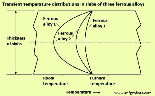
Fig 1 Effect of thermal conductivity on heat flow and internal temperature distribution
Solid materials which are heated in industrial furnaces are not necessarily continuous. Many times, the charge consists of coiled strip material or separate pieces piled to various depths or close side by side. In such cases, heat only can flow from one piece to the adjacent piece through small contact points on their surfaces, or through gas filled spaces, the thermal conductivity of which is very small. A stack of flat plates is an example of very low conductance. Even very small gaps constitute a big thermal resistance than solid metal. A stack cannot be treated as a solid, since thin air spaces are insulators. The differing air gaps in a stack result in bad non-uniformities in temperatures.
Rapid heat flow in each piece of a piled charge is obtained only by circulation of hot gases through the piled material by convection and gas radiation. These gas masses are to be constantly replaced with new hot gas since they have low mass, low specific heat, and thin gas beam thickness, so they cool quickly without delivering much heat to the loads. For uniform heating and precise reproducibility, piling of pieces of materials are to be avoided.
Heat transfer to the surface of the furnace charge – In furnace practice, heat is transferred by three modes namely (i) conduction, (ii) convection, and (iii) radiation. There are some essentials of heat transfer which are helpful to designers and operators of industrial furnaces. Most industrial furnaces, ovens, kilns, incinerators, boilers, and heaters use combustion of fuels as their heat source. Combustion, as used in industrial furnaces, comes from rapid and large chemical reaction kinetics and this result into conversion of chemical energy to sensible heat (thermal) energy. Increasing fuel and oxidizer (usually air) mixing surface area or increasing temperature of the reactants can cause faster combustion reactions, usually resulting in higher heat source temperatures. Fuel oxidation reactions are exothermic, so they can develop into a runaway condition (e.g. thermal energy being released faster than it can be carried away by heat transfer). This positive feedback can cause an explosion.
A flame is a thin region of rapid exothermic chemical reaction. An example is a Bunsen burner flame. In a Bunsen burner, a thoroughly premixed laminar stream of fuel gas and air is ignited by an external heat source, and a cone-shaped reaction zone (flame front) forms. Turbulence increases the thickness and surface area of the reaction zone, resulting in higher burning velocity. Laminar burning velocity for natural gas is around 18 metres per minute (mpm) while the turbulent burning velocity can be two to ten times faster. In a laminar flame, thermal expansion from chemical heat release can combine with increased reactivity caused by higher temperatures, resulting in acceleration to a turbulent flame. Except for long luminous flames, most industrial flames are turbulent.
Conduction heat transfer – Conduction heat transfer is molecule-to-molecule transfer of vibrating energy, usually within solids. Heat transfer solely by conduction to the charged load is rare in industrial furnaces. It occurs when cold metal is laid on a hot hearth. It also occurs, for a short time, when a piece of metal is submerged in a salt bath or a bath of liquid metal.
If two pieces of solid material are in thorough contact (not separated by a layer of scale, air, or other fluid), the contacting surfaces instantly assume an identical temperature somewhere between the temperatures of the contacting bodies. The temperature gradients within the contacting materials are inversely proportional to their conductivities (Fig 2).
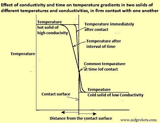
Fig 2 Effect of conductivity and time on temperature gradients in two solids of different temperatures and conductivities, in firm contact with one another
The heat flux (rate of heat flow per unit area) depends not only on the temperatures of the two solids but also on the diffusivities and configurations of the contacting solids. In practice, comparatively little heat is transferred to (or abstracted from) a charge by conduction, except in the flow of heat from a billet to water-cooled skids.
When a piece of cold metal is suddenly immersed in liquid salt, lead, zinc, or any other liquid metal, the liquid freezes on the surface of the cold metal, and heat is transferred by conduction only. After a very short time, the solid jacket, or frozen layer, remelts. From that time on, heat is transferred by conduction and convection.
Convection heat transfer
Convection heat transfer is a combination of conduction and fluid motion, physically carrying heated (or cooled) molecules to another surface. If a stream of gaseous fluid flows parallel to the surface of the solid, the vibrating molecules of the stream transfer some thermal energy to or from the solid surface.
A ‘boundary layer’ of stagnant, viscous, poorly conducting fluid tends to cling to the solid surface and acts as an insulating blanket, reducing heat flow. Heat is transferred through the stagnant layers by conduction. If the main stream fluid velocity is increased, it scrubs the insulating boundary layer thinner, increasing the convection heat transfer rate. The conductance of the boundary layer (film coefficient) is a function of mass velocity (momentum, Re number).
In furnaces which operate below 600 deg C, heat transfer by convection is of major importance since radiation is weak there. Modern high-velocity (high-momentum) burners give high convection heat transfer coefficients. High velocities often provide more uniform temperature distribution around a single piece charge, or among multiple piece charges, since more mass flow carries additional sensible heat at more moderate temperatures. At low furnace temperatures, high rates of total heat transfer can be obtained only by high gas velocities since heat transfer by radiation at around 550 deg C is less than one-tenth of what it is at around 1200 deg C. High-velocity (high momentum) burners are widely used to fill in where radiation cannot reach because of shadow problems.
Radiation heat transfer
Radiation between solids – Heat is radiated by solids even at low temperatures. The net radiant heat actually transferred to a receiver is the difference between radiant heat received from a source and the radiant heat re-emitted from the receiver to the source. The net radiant heat flux between a hot body (heat source) and a cooler body (heat receiver) can be calculated by Stefan-Boltzmann equations.
Emissivity and absorptivity of materials are important properties for radiation between solids. Emissivity is the radiant heat emitted (radiated) by a surface, expressed as a decimal of the highest possible (black body) heat emission in a unit time and from a unit area. Emittance is the apparent emissivity of the same material for a unit area of apparent surface which is actually much greater, due to roughness, grooving, and so on. Absorptivity is the radiant heat absorbed by a surface per unit time and unit area, expressed as a decimal of the most possible (black body) heat absorption.
Engineers use emissivity value of 0. 85 in conventional refractory lined furnaces. However, the temperature, surface condition, and alloy can make considerable difference. As an example, if stainless-steel strip is heated in less than three minutes in a catenary furnace, the emissivity may not change even though the temperature increases from ambient to 1100 deg C. By measuring both strip surface temperature and furnace temperature, it has been possible to revise heating curve calculations, assuming that oxidation has not changed the emissivity or absorptivity during the heating cycle.
Radiation from clear flames and gases – There are two origins of radiation from the products of combustion to solids. The two origins of radiation are (i) from clear flame and from gases, and (ii) from the micron-sized soot particles in luminous flame. Radiation from clear gas does not follow the Stefan-Boltzmann fourth-power law. The only clear gases which emit or absorb radiation appreciably are those having three or more atoms per molecule (triatomic gases) such as CO2, H2O, and SO2 (sulphur di-oxide). An exception is diatomic CO, which gives off less radiation. The other diatomic gases, such as O2, N2 (and their mixture, air), and H2 have only negligible radiating power.
Gaseous radiation does not follow the fourth-power law since gases do not radiate in all wavelengths, as do solids (gray bodies). Each gas radiates only in a few narrow bands. Radiation from clear gases depends on their temperature, on the partial pressure or percent volume of each triatomic gas present, and on the thickness of their gas layer.
The temperature of a radiating gas gets lower in the direction of gas travel. To maintain active gas radiation, the gas is to be continually replaced by new hot gas, which also improves convection. Higher gas feed velocities reduce the temperature drop along the gas path. This factor is very critical in maintaining good temperature uniformity in high temperature industrial furnaces.
The furnaces are often designed on the basis of refractory radiation heating the charge, with usually reasonable results, but some situations cannot be explained by refractory radiation alone. Direct radiation from furnace gases generally delivers 62 % (+/- 2 %) of the heat to the charge, and refractories transfer the remaining 38 % (+/- 2 %). Gas temperatures needed to transfer the heat to refractory and charge are generally much higher than generally assumed.
Radiation from luminous flames – If a fuel-rich portion of an air/fuel mixture is exposed to heat, as from a hotter part of the flame, the unburned fuel molecules polymerize or suffer thermal cracking, resulting in formation of some heavy, solid molecules. These soot particles glow when hot, providing luminosity, which boosts the flame’s total radiating ability.
If fuel and air are not thoroughly mixed promptly after they leave the burner nozzle, they can be heated to a temperature at which the hydrocarbons crack (polymerize). Further heating brings the resulting particles to a glowing temperature. As O2 mixes with them, they burn. As the flame proceeds, formation of new soot particles can equal the rate of combustion of previously formed particles. Farther along the flame length, soot production diminishes, and all remaining soot is incinerated. This series of delayed-mixing combustion processes are to be completed before the combustion gases pass into the flue. If the flame is still luminous at the flue entry, smoke can appear at the stack exit. Smoke is soot that has been cooled (chilled, quenched) below its minimum ignition temperature before being mixed with adequate air.
The added radiating capability of luminous flames causes them to naturally cool themselves faster than clear flames. This is performing their purpose—delivering heat. The cooling phenomenon can negate some of the gain from the higher luminosity (effective emissivity).
Luminous flames often have been chosen because the added length of the delayed mixing luminous flames can produce a more even temperature distribution throughout large combustion chambers. As industrial furnaces are supplied with very high combustion air preheat or more oxy-fuel firing, luminous flames can enable increases in heat release rates.
Fuels with high C/H2 ratios (most oils and solid fuels) are more likely to burn with luminous flames. Fuels with low C/H2 ratios (mostly gaseous fuels) can be made to burn with luminous flames namely (i) by delayed mixing, injecting equally low-velocity air and gas streams side-by-side, and (ii) by using high pressure to ‘shoot’ a high-velocity core of fuel through slower moving air so that the bulk of the air cannot ‘catch up’ with the fuel until after the fuel has been heated (and polymerized) by the thin ‘sleeve’ of flame annular interface between the two streams.
Flames from solid fuels can contain ash particles, which can glow, adding to the flame’s luminosity. With liquid and gaseous fuels, flame luminosity usually comes from glowing C and soot particles. The effective flame emissivity, as measured is usually between that of the POC gases and a maximum value of 0.95, depending on the total surface area of solid particles. Normally, heat transfer from a luminous flame is greater than that from a clear flame having the same temperature. The difference in the rate of heat transfer is quite noticeable in furnaces for reheating steel and metals. The difference becomes more pronounced at high temperature, where the radiating power of each triatomic gas molecule increases, but the gain is partially canceled by the decreasing density of radiating molecules per unit volume.
In another phenomenon, the bands of gaseous radiation hold their wavelengths regardless of temperature. At higher temperatures, however, the area of high intensity of solid radiation (glowing soot and C particles) moves toward shorter wavelengths (away from the gas bands). In higher temperature realms, radiation from clear gases does not increase as rapidly as radiation from luminous flames.
Flame radiation is a function of many variables such as C/H2 ratio of the fuel, air/fuel ratio, air and fuel temperatures, mixing and atomization of the fuel, and thickness of the flame. Some of these can change with distance from the burner. Fuels with higher C/H2 ratio, such as oils, tend to make more soot, so they usually create luminous flames, although blue flames are possible with light oils. Many gases have a low C/H2 ratio, and tend to burn clear or blue. It is difficult to burn tar without luminosity. It is equally difficult to produce a visible flame with blast furnace (BF) gas or with H2.
When comparing luminous and nonluminous flames, it is important to remember (i) soot radiation (luminous) usually ends where visible flame ends because soot is most often incinerated at the outer surface or skin of the flame, where it meets secondary or tertiary air, and (ii) gas radiation (nonluminous) occurs from both inside and outside the visible flame envelope, greatly increasing the uniformity and extent of its coverage, although gas radiation within the flame is somewhat shadowed by any surrounding soot particles or triatomic gases, and gas radiation outside the flame can be from cooler gases.
The effect of excess fuel on flame radiation is considerably greater than the effect of less excess air. The merits and demerits of clear flames versus long luminous flames have been debated for years. Modified burners and control schemes are helping to utilize the best of both. A problem common to several burner types is change of the flame characteristic as the burner input is turned down. Problems with some clear flame burners are (i) movement of the hump in the temperature profile closer to the burner wall as the firing rate is reduced, and (ii) at lower input rates, temperature falls off more steeply at greater distances from the burner wall (e.g., the temperature profile of a burner firing at 50 % of its rated capacity or below is at its peak temperature (maximum heat release at or near the burner wall, falling off further from the burner wall). At lower firing rates, the temperature drop off gets worse. At higher firing rates, the burner wall temperature decreases as the peak temperature moves away from it. In some steel reheating furnaces at maximum firing rate, the temperature difference between the burner wall and the peak can be 150 deg C.
The problem of a temperature peak at the far wall during high fire is aggravated by spur of furnace gases into the base of the flame, delaying mixing of fuel with O2. If the burner firing rate is increased, the spur of the products of complete combustion increases exponentially. Resulting problems are many. When side-firing a furnace at low firing rate, the peak temperature is at the burner wall, but at maximum firing rate, the peak temperature can be at the furnace centre or the opposite wall. Thus, the location of a single temperature control sensor is never correct. If the temperature sensor is in the burner wall, low firing rates have peak temperature hugging the furnace wall and driving the burner to low fire rate resulting into the rest of the furnace width receiving inadequate input. At high firing rates, a sensor in the burner wall is cool while the temperature away from the burner wall is very high, perhaps forming liquid scale on the surfaces of the charge pieces at the centre and/or far wall. To remedy this issue, inexperienced operators can lower the set point, reducing the furnace heating capacity.
Another example of the effect of the problem occurs with the bottom zone of a steel reheating furnace when fired longitudinally counter flow to the load movement, and with the control sensor installed 3 metre (m) to 6 m from the (end-fired) burner wall. At low-firing rates, with the zone temperature set at 1300 deg C, the burner wall can rise to higher than 1370 deg C. At that temperature, scale melts and drips to the floor of the bottom zone where it can later solidify as one big piece. At high firing rates, the peak temperature can move beyond the bottom zone T-sensor, possibly melting scale some distance toward the charge end of the furnace. Again, to avoid the problem, operators can lower temperature control settings, reducing the furnace capacity.
Control of the aforementioned problems requires an additional temperature sensor in each zone and a means for changing the mixing rate characteristic of the burner in response to the temperature measurements. Burners with adjustable spin (swirl) can be set to prevent much of the problem, especially if combined with a low-fire, forward-flow gas or air jet through the center of the burner. Such a jet is typically sized for 5 % of maximum gas or air flow.
Long, luminous flames, either laminar type or turbulent type, tend to have much less temperature hump and do not change length as rapidly when input is reduced. They can be great ‘levelers’, providing better temperature uniformity.
This information on in-flame soot radiation and triatomic gas radiation has been known for some time, but recent developments may be changing the picture. Use of oxy-fuel (100 % O2), both of which elevate flame turndown. The major gain from oxy-fuel firing is from more intense radiation heat transfer because of the higher concentration of triatomic gases, due to the elimination of N2 from the POC. This also decreases the mass of gas carrying heat out the flue (reducing stack loss). In another development, some lean premix gas flames (designed for low NOx emissions) make a ubiquitous flame field (seemingly transparent) through much of the chamber.
制造工艺