

高炉炉料的准备和装料
高炉炉料的准备和装料
高炉 (BF),除了它的炉膛外,基本上是气体和炉料颗粒的通道,它们在高炉中以逆流方向移动。 BF 稳定运行的基本要求是在炉内保持一个波动不大的移动炉料层。具体来说,就是要形成稳定的气流和没有混合料层的料层结构。这些是彼此密切相关的。气流的稳定性几乎完全取决于配料的渗透性,这取决于配料的填充结构(粒度、粒度分布和细颗粒比等),以及配料的下降行为,即固体流动。
原则上,BF 处理是一个复杂的逆流、并流和/或交叉流的 4 相流系统,由固体、气体、液体和粉末组成。相的相互作用是不同的,并且位于BF的不同区域。 BF 中通常有五个不同的区域(图 1),即 (i) 块状区域、(ii) 粘性区域、(iii) 焦炭活性区域、(iv) 燃烧区域(滚道)和 (v) 死区(炉膛中心区)。由于高炉特定区域的负荷阶段差异和独特的相互作用,在高炉的整个体积中不存在单一的负荷运动或流动模式。
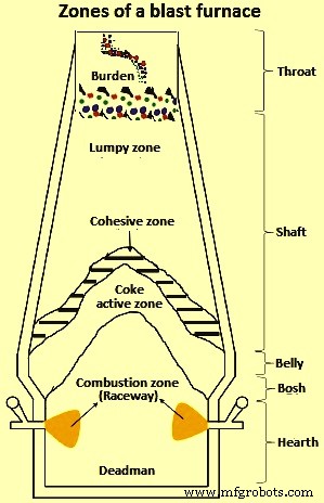
图 1 高炉区域
BF 中通常有四种不同类型的固体流动区域。这些是 (i) 活塞流区域,它与从原料线和位置刚好高于粘性或熔化区的物料的均匀下降速度相关,(ii) 停滞流动区域(死人),它是部分不连续的质量炉膛中心部分的反应焦炭颗粒,(iii) 部分停滞流动区域,该区域与部分反应焦炭颗粒缓慢移动的死区相邻,以及 (iv) 会聚流动区域,其周围在停滞区-炉壁距离内具有明显颗粒速度变化的滚道。
炉料下降的机理包括矿石和焦炭通过反应、熔化和燃烧而消失,料层顶部和炉壁附近的料粒运动,细粒原料渗入炉膛。影响高炉炉料下降的因素包括原料状况(粒度、强度、炉料分布-矿焦比)、滚道状况(辅助燃料喷射)、炉膛内壁型材等
BF 操作对轮廓、粒度分布和所有影响性能和生产率的因素非常敏感。为确保高炉的平稳运行,必须优化库存线上的固体炉料(铁矿石、焦炭和熔剂)的分布。通过适当控制库存线级别的负担分布来控制BF的内部状态非常重要。
高炉的炉料是为了满足高炉平稳运行所需的某些要求。它是为了满足机械、化学和热方面的要求。带电物料要形成坚固且可渗透的结构,以承载负荷并允许高炉竖井中的还原气体通过。应避免负载过早分解,因为细粉的形成会干扰竖井中的还原气流,从而降低工艺效率。因此,高炉中细料的装料将被取消。
为了最大限度地提高生产率和确保稳定的熔炉运行,需要优化区域内的炉料向下移动、化学反应、热分布和液体移动。通过优化炉内工艺和周边操作,如彻底控制原材料的物理和化学性质和颗粒分布,可以实现稳定和高炉生产率运行。炉内工艺(带料物理变化和化学反应)和外围辅助操作(炉料堆放、回收、运输、储存、卸料、输送和装料)是高炉工艺平稳运行的重叠功能,无法处理因为它们是相互关联的进程,所以是孤立的。
BF 炉料即铁矿石、焦炭和熔剂被归类为散装固体,因为它们与彼此接触的离散固体颗粒相似。这些材料与任何粒状材料一样,都是由相互作用的粒子制成的。一般来说,这些材料的内部结构是相当进化的。根据表 1 中给出的散装固体材料分类,高炉炉料大体上分为破碎/不连续固体。
| 表 1 散装固体尺寸分类的定性术语 | |||
| Sl. No. | 尺寸范围,单位mm | 典型术语 | |
| 组件 | 批量 | ||
| 1 | 小于0.1 | 粒子 | 粉末 |
| 2 | 0.1 到 -1 | 颗粒 | 粒状固体 |
| 3 | 1 到 -3 | 谷物 | 破碎的实体 |
| 4 | 3 或更高 | 肿块 | 破碎的实体 |
通常,任何形式的散装固体的处理在保持均匀性方面都存在挑战。考虑到与散装固体的离散成分具有相同物理和化学性质的颗粒,已经表明散装固体的混合(有意或无意)不可避免地导致成分的自然分配。这个概念通常被称为分离(去混合)。自然和/或工业上,散装固体的离散成分之间的分离可能是有益的(例如在物理分离过程中)或有害的(例如在混合过程中),具体取决于产品或子单元操作的预期功能。
配料处理的理论方面
高炉炉料包括焦炭、烧结矿、球团矿、校准块矿 (CLO)、石灰石、白云石、锰矿和石英岩。由于工艺的性质,BF 工艺本质上对炉料尺寸、分布和强度敏感。 BF 中原料的分布影响气体向上流动以及过程中不同阶段之间的过程化学、传热和传质。材料的强度非常重要,因为随着材料的下降,负载会增加。随后在高温和高压下发生的化学反应进一步损害了负载的完整性,在这种情况下,磨损和破损很普遍。
BF 焦炭在 BF 操作期间用作支撑结构材料,因为它是通过部分溶解反应下降到 BF 炉膛的唯一炉料。它占铁水 (HM) 生产成本的很大一部分。近年来,有动力用廉价的替代碳源替代焦炭。通常使用的替代方法是在通常称为煤粉喷射 (PCI) 的过程中在滚道中直接喷射煤。然而,由于焦炭含量不足的高炉炉料渗透率降低,导致炉膛堵塞和挂炉,进而导致炉滑发生,因此更换的程度存在理论上的限制。
BF 炉料的组成决定了炉内工艺变量,例如熔化温度、软化以及一些还原参数,如果炉料分布没有优化,这些都会对生产产生不利影响。面对这些限制和挑战,需要适当控制负担分配。 BF炉料的典型尺寸范围见表2。
| 表2 BF炉料的典型尺寸范围 | |||
| Sl. No. | 材质组件 | 以毫米为单位的尺寸 | |
| 最低 | 最大值 | ||
| 1 | 高炉可乐 | 25 | 50 |
| 2 | 校准块矿 | 10 | 30 |
| 3 | 烧结 | 5 | 30 |
| 4 | 铁矿石颗粒 | 8 | 20 |
| 5 | 石灰石 | 10 | 40 |
| 6 | 白云石 | 10 | 40 |
| 7 | 锰矿 | 10 | 40 |
| 8 | 石英石 | 10 | 40 |
| 9 | 坚果可乐 | 10 | 25 |
颗粒流的物理现象和流动结构,包括高炉炉料,乍一看似乎很简单,但实际上它们表现出复杂的行为,难以理解和预测。由于缺乏有关此类过程的混合和分离参数的直接信息,情况变得更加复杂。然而,由于高炉炉料聚集体尺寸大,物料粒度分布大,偏析倾向是一个严重的操作问题,需要尽可能减少。
散装物料处理和流动行为
尽管粉末力学的元素早在 19 世纪中期就已为人所知,但对散装材料行为和流动的基本理解仍然不够充分。这主要归因于流动物理的独特而复杂的特性。散装材料的处理表现出有趣的行为。一方面是由于单个粒子特性而导致的粒子宏观混合物去混合的能力。这些观察结果主要是由于这些材料具有图案发展和自组织的自然趋势。这种现象主要是由于散装材料具有类似流体的特性。
尽管散装材料具有类似流体的特征,并且其本身更像固体,但整体行为和特征与这些常见物质形式的观察结果完全平行。通常,与动力学受常温影响的其他形式的物质不同,这种影响在散装材料动力学中可以忽略不计。有助于了解流体典型的混沌平流或混合效应的竞争是导致在散装材料中观察到的自组织趋势的原因,而流动引起的偏析没有流体现象。
基本过程的宏观行为主要受微观粒子间接触和摩擦力的控制。考虑到高于 5 mm 的 BF 电荷材料尺寸,表面力的影响,即静电、范德华力和毛细管效应可以忽略不计。此外,装载材料的流动行为对应于非粘性固体,因为粘性趋势是粒径小于 10 微米的超细或超细粉末材料的典型特征。
散装物料流向分类
散装物料的流动可按其成分分类,可定义为具有相同粒径、密度、形状等物理特性的一组颗粒。流动结构通常难以分析,并且受到粒子间相互作用以及外部激发和边界条件的显着影响。因此,没有一种包罗万象的通用方法来全面描述所有散装物料的流动结构。根据颗粒接触的时间段,可以建立几种不同类型的区分流动结构。
在散装材料流动的情况下,颗粒流动显示出数量可变的亚稳态非稳态。如果没有诸如振动之类的外部干扰,这些亚稳态不稳定状态会无限期地持续下去。这种状态的维持很大程度上取决于粒子和边界接触的时间段。这取决于相对于流体(气体或液体)总体积的固体体积分数。因此,颗粒材料的流动通常分为稀的或密的(以接触为主),具体取决于固体体积分数。根据接触的时间段,密集流动可以细分为碰撞主导或接触主导。在这三个分类中,行为和特征流对于特定分类是独特的。流体-粒子相互作用(即升力和阻力)在稀流中主导粒子运动,而粒子与粒子或粒子与壁的碰撞或连续的粒子与粒子接触在稠密流中占主导地位。
图 2 显示了稀流、以碰撞为主的密流和以接触为主的密流之间的散装物料分类示意图。图 2 中给定的稀散装物料分类可以在旋风分离器、流化床和高炉料斗中观察到分别流动。高炉散装物料在卸料、储存和运输过程中的密集(碰撞和接触为主)流动是典型的。
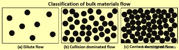
图2散装物料流向分类
密集物料流的两种分类
两种密集流态的共同特征是结构进展,是长度和时间尺度的函数。通常,由于颗粒的重新定向,这会导致图案形成。这种材料的取向是由中等规模的结构驱动的。单个粒子尺度,更好地称为微观尺度,通过中间尺度与宏观或连续尺度分开。了解颗粒流组件的复杂颗粒相互作用对于量化分离或分离现象至关重要。在这方面,有待建立宏观结构(整体)行为与底层微观结构(离散)动力学之间的关系。
以碰撞为主的流 – 在以碰撞为主的流动中,流动是分散的、分散的和充满活力的,粒子主要通过近瞬时和二元碰撞相互作用。惯性效应可以忽略。碰撞是非弹性的,并且在粒子与粒子或粒子与边界相互作用期间会耗散能量。由于碰撞是耗散的,因此在一定程度上需要工作源来维持颗粒材料的“流动性”。由于碰撞的耗散性质,观察到了独特的流动行为和模式,例如聚集和密度波。密度波是一种与颗粒温度相关的现象,颗粒流动不均匀,而是进入速度与平均速度不同的区域。
以联系人为主的流程 – 在以接触为主的流动中,粒子与粒子的碰撞具有很强的相关性,既不是二元的也不是瞬时的,而是持久的和多重的。该流动显示了两个有趣的特征场景,其中存在临界剪切应力,低于该临界剪切应力可能流动,以及流动开始时对剪切速率的复杂依赖性。由于这种依赖性,完整的流动结构需要包含与接触主导流动相关的粘塑性特征。
基于不同的处理和一些考虑,提出了几个本构定律,例如通过局部旋转增加一个自由度,引入随机流动规则和修改动力学理论输运系数,如粘性项、碰撞频率和耗散项。最近的一个公式,其中一个称为惯性数的参数似乎是一个稳健的公式,能够再现接触主导流动的各种粘塑性特性。惯性数是剪切速率乘以颗粒质量的平方根除以压力。
粒状物料的混合与分离
颗粒状材料的处理非常复杂,尤其是当由于自然偏析(去混合)趋势而需要均匀和均匀分布时,尤其是在材料尺寸变化很大的情况下。与混合促进均匀性的流体过程不同,颗粒流动类似于混合和分离镜像,其中延长的混合趋势促进分离(分离)。因此,对于经过重复处理过程的高炉料,将混合视为无声特征是有用的。
粒状材料的自然顺序是分离或偏离均匀行为。根据颗粒材料所处的系统状态(装料、存储、卸料和运输),存在不同形式的分离发生机制。偏析的主要驱动因素是粒度差异、密度差异以及微观性能差异,例如摩擦效应、恢复系数和休止角。在这些驱动因素中,粒径似乎是决定颗粒分离行为的最重要因素。
粒料分离机制
在一项最小化偏析的研究中,已经提出了 13 种粒状材料偏析的机制。然而,这些机制中的大多数是其他机制的特殊或重叠情况。考虑到这一点并具有灵活性,分类粒状材料偏析已简化为五个主要机制。在这五种简化机理中,流化和团聚偏析机理分别是指细颗粒和粘性颗粒,不适用于高炉炉料。因此,下文介绍适用于高炉炉料装料、储存、卸料和运输的其余三种主要分离机制。
渗滤或动态筛分机制 – 当具有尺寸分布范围的颗粒相互作用时(例如在材料储存箱中),自发固结滴流会发生,较小的颗粒通过大部分空隙向下渗透和筛分。自然地,当颗粒材料流动时,颗粒间隙变宽,当这种情况发生时,就会产生空隙。小颗粒可以挤入大颗粒下方的小空隙中,但相反的情况发生的可能性要小得多,从而导致较小颗粒的净分离通量向下远离自由表面。这个动作通常被称为渗透。在稳定状态下,颗粒与具有许多细颗粒的底层分离。渗流机理如图 3 所示。在粒径为 d1 和 d2 的二元系统中,其中 d2 大于 d1,当 d1/d2 小于或等于 0.1547 时会发生自发筛分。首次使用这一临界比值,根据渗流机制推导了滑槽流中颗粒大小差异引起的偏析的详细模型。
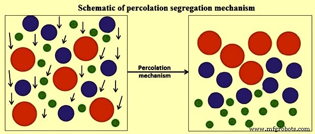
图3 渗流分离机理示意图
通过振动运动的剪切感应强化了渗流分离机制,例如具有甚至大尺寸和高密度颗粒迁移到顶部的振动筛。这表明振动系统中的分离只需要几何考虑。简而言之,要发生渗流偏析机制,主要需要满足三个条件,即(i)筛分的临界尺寸比,(ii)小颗粒需要非粘性才能通过空隙,以及(iii)存在足够的应变或粒子间运动以增加细粒子向多个间隙取向的概率。
轨迹机制 – 轨迹驱动的分离机制通常出现在装料转移点,主要是填充到储料仓、从储料斗卸料和在传送带末端卸料,如图 4 所示。在一项研究流动条件以确保顺畅流动的研究中对粒状物料,已经指出不同粒度的物料由于不同的摩擦阻力以不同的速度运动,从而导致物料偏析。考虑到水平投射到流体中的粒子,已经在数学上解释了轨迹分离的机制。考虑到一个直径为 d、密度为 Dp 和受斯托克斯定律控制的阻力的小粒子,已经表明,具有初始投射速度 Vi 的粒子在粘度为 Vf 和密度为 Df 的流体中行进的最大距离 X,如公式 X =Dp.Vi.(Dp)2/18 Vf 中给出的。然而,当考虑 BF 装料材料尺寸并假设阻力可忽略不计时,粒子的轨迹由无量纲轨迹方程给出。无量纲轨迹方程为 y/x =tan A – [g/2 (cos A)2]。 x/Vi,其中 x 和 y 分别是水平和垂直空间坐标,A 是倾角,g 是重力加速度,Vi 是自由飞行时的初始速度。从方程可以看出,粒子的轨迹与大小(质量)无关,而是与每个粒子相关的自由落体开始时的随机速度无关。
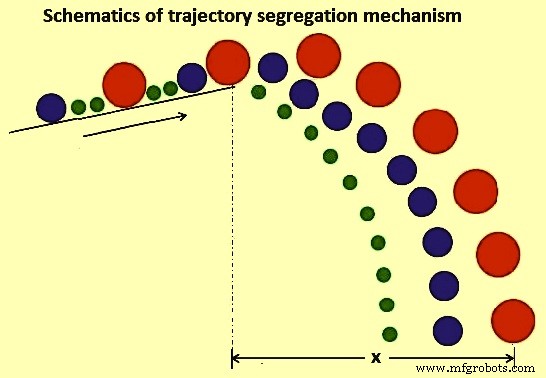
图4轨迹分离机制示意图
微观属性差异机制 – 在这种机制下,存在三种效应,即(i)摩擦效应(ii)恢复系数效应和(iii)休止角效应。
对粒状材料的摩擦效应的研究表明,具有不同静摩擦系数 F 的两种组分的粒状材料通常会偏析。在研究过程中,考虑了质量为 m、高度为 h、滑动摩擦系数为 Fs、滚动摩擦系数为 Fr 和半径为 r 的球形颗粒,在倾斜角为 A 的斜坡上放电的情况,如如图 5 所示。考虑到能量守恒原理,如果处于不稳定平衡状态的粒子满足方程 m.g.sin A.r =m.g.cos A. Fr 中给出的动量方程。在这个方程中,粒子行进距离 X 可以通过方程 X =(h/Fs).(Cos A)2.(1-Fs/tan A) 和 X =(r.h/Fr).(cos A) 获得2. (1- Fr/r.tan A)。这两个方程分别给出了考虑滑动和滚动摩擦系数的派生粒子行进距离。从这些方程可以看出,当考虑滚动摩擦系数时,颗粒行进距离取决于颗粒直径,这会导致偏析。相反,滑动摩擦效应表现出颗粒大小和质量的独立性。
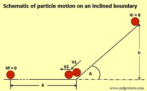
图5倾斜边界上的粒子运动示意图
恢复系数效应的机制原则上是一种动态效应。当粒子碰撞或粒子撞击系统边界时,它们以不同的速度反弹,最终位置由界面弹性确定。该机制的示例是将颗粒装入堆或存储箱中。在撞击堆的顶部时,几乎没有弹性的粒子不会反弹,而是被困在它们的位置。相反,那些具有高弹性的粒子会反弹并在远离沉积点的某个地方找到最终位置,并可能集中在堆的外围。
在休止角效应的情况下,在颗粒材料的堆放过程中观察到偏析的机制。当建立一个堆时,可以看出倾斜角(休止角)取决于材料的类型,与粒子的数量无关。在一项关于旋转滚筒休止角的边界效应的研究中,已经指出轴向偏析受静态或动态休止角的影响。原则上,休止角效应取决于材料的粒径、分布、形状和摩擦力等参数,因此,由于包含其他变量的效应,它成为一种混合机制。
粒状物料偏析的分类
粒状材料的分离根据所考虑的过程所考虑的变量进行分类。主要根据 (i) 粒子的物理特性(即尺寸、密度或形状偏析),(ii) 能量输入(即振动、重力或剪切偏析),(iii) 粒子运动方向(即水平,或垂直分离),以及 (iv) 使用的设备(即料斗、溜槽或传送带)。
然而,作为产生隔离的机制而更为人所知的自然或既定过程似乎是最常见的分类方法。偏析被广泛认为是一种表面现象。因此,观察到的不同机制与表层下方的颗粒无关。原则上,这些机制可以通过仅考虑移动表层粒子的行为来解释。在各种类型的隔离中,原则上和大多数情况下,总体隔离机制是几种相互作用机制的组合。例如,筛分偏析可以被认为是渗滤和位移/迁移偏析的一种特殊情况,因为它们都具有小颗粒相对于大颗粒向下过滤的原理。
分离量化
尽管对离析对颗粒材料流动的机制和影响有一些了解,但由这种现象引起的问题需要得到充分的限制,有必要从避免发生离析转向控制离析。在这方面,需要精确的定性和定量分离测量方法来完全了解和控制影响,特别是对于经历重复处理过程的高炉炉料。在这种情况下,对粒子分布的完整描述是一项重要的工作。然而,为了准确地对炉料线进行负荷,必须了解颗粒材料分布以及颗粒流中混合和偏析的量化。
隔离测量指标 – 原则上,离析是复杂颗粒材料流的一小部分。此外,颗粒流的不透明性使得在分离研究期间物理提取有用数据实际上很困难,如果不是不可能的话。将理论公式适当地结合到数学建模模拟中可以更容易地更好地表征这种系统的颗粒流混合和分离。偏析的量化是一项重要的任务,因为它涉及完全包含导致偏析的因素和粒子运动方程之间的相互关系。然而,已经提出了一些用于测量颗粒混合质量的指标,这些指标可以用作分离的定量测量,它们通常以统计术语或无量纲数字术语表示。常用的混合和分离指标是相对标准偏差 (RSD),它仅考虑单组分系统。该 RSD 分离度量是一种反射性工业应用度量,因为它为整个系统提供了混合的宏观混合状态。
混合和隔离测量指标是正在使用的许多索引的支柱。重要的是要了解集中样本和特定方差的测量值用于定义混合和/或分离指数。尽管量化提供了相当丰富的信息,但这种表征的主要缺点是在测量域上进行平均,而忽略了仍未发现的粒子到粒子分布的变化。此外,在关于颗粒材料混合和偏析的经典和基本概念中,颗粒偏析过程被定义为一种表面现象。
大量研究表明并证明,不同形状的搬运设备、操作方式和材料特性可能与材料的混合和分离行为相关。仍然存在的主要挑战是有一个统一的表征方法,它不仅描述了混合动力学,而且从根本上解决了更复杂的分离现象。一种新的方法是表征装料系统内原材料中颗粒与颗粒关系的演变,以便在时间和空间上告知混合和分离的程度。该方法的核心是基于粒子与其最近邻之间关系的某些方面可以用来推断粒子动力学演化过程的有用见解的想法。
颗粒流机械分离模型
已经看到,分离动力学被广泛且一般地构建为数理统计和概率框架。这种方法的明显限制是,不能绝对反映过程的物理性质,而且无法规定发生分离的方向。这限制了概括的可能性,因为知识是非常经验的。 In the first pioneering study to develop mechanistic models which incorporate all the physics surrounding the prevalent de-mixing tendencies that occur in real granular flow system, the application of kinetic theories for mixtures of granular materials has been applied to study segregation tendencies based on percolation mechanism. Using a combination of statistical and dimensional analysis, the developed formulations hold for negligible enduring frictional contacts with shear rates sufficiently high so that the dominant contributions to the total stresses are due to particle to -particle and particle to boundary collisions. In this study, it has been observed that in a chute flow with high solids volume fractions, there is a high probability of small voids formation relative to big ones. The resulting effect of such a postulation is that small particles sieves through and collects at the base of the bed. This results in a net segregation flux in a direction normal to the chute surface of the small particles.
In as much as the mechanistic models described above give some intended physical appreciation in segregation description, evaluation of key fundamentals such as dispersion coefficients of such granular flows are not small and cannot be established by the above models. In this direction, one study suggested mixed statistical and mechanical interactions based on the kinetic theory of dense gas systems since they give a general understanding of causes of granular flow segregation.
Clustering occurs as granular flow experiences damping as energy is lost after collisions. The change in velocity and movement is non-uniform hence the clusters are formed. Hence, constitutive equations have been proposed based on a kinetic theory for collisional rapid flows. The utilization of the kinetic theory expressions for the analysis of granular segregation shows that it can be used only for inelastic and different sized particles at low volume fractions. This is a limitation as typical granular flow systems are contact-dominated flows with high solids volume fractions. The application of the theory is more useful in case there are established constitutive equations for inelastic, different sized particles and high solids volume fractions.
It is seen that the granular flow resembles mixing and segregation mirror image in which the prolonged mixing tendency promotes segregation. The concentration gradients results in mixing whereas the individual contributions of pressure and temperature gradients produce segregation in granular flow systems characterized by particles with particle size range distributions and material density differences.
The theoretical aspects of the bulk handling of the materials have given a general but compact back ground on granular flow, free surface segregation, mechanisms and theoretical approaches in granular material processes. BF burden material storage, handling and transportation processes are susceptible to the fate associated with segregation. For example, the BF sinter material is known to have more in-bin size segregation and more out of bin size variation than the BF coke.
BF charging system
The charging system of the BF iron-making process can generally be described as a network of equipment and mechanisms designed to charge materials into the BF in a certain sequence, quantity and at a rate which ensure that the specified furnace productivity and prescribed stock-line level is maintained. The charging system consists of three sub-systems which are essentially responsible for (i) batching (ii) transportation, and (iii) charging into the furnace respectively. Batching is done in the stock-house which receives the bulk solid feed materials from their various sources (stockpiles, sinter plant, and coke ovens), storing each material in individual bins to provide several hours of feed material for usual BF operations. The batching process includes screens, weigh-hoppers, conveyor belts, feeders and control systems to prepare batches of charge materials. Transportation provides the means for the delivery of the materials to the top of the furnace. Normally, this is done with either by the belt conveyor system or the skip hoist arrangement. The third sub-system consists of a network of equipment and mechanisms for the charging and control equipment. The overall charging system is interconnected and controlled by an automated charge programme.
Under some conditions, furnace productivity can be limited due to the capacity of the batching (stock-house) process to deliver charge materials. This occurrence is mainly due to transient charge materials flow, equipment settings and charge requirement (burden ratios). A typical source of transient change in charge composition is caused by changes in materials delivered to the stock-house bins and is usually referred to as ‘stock transitions’. This normally occurs when the reclaimed material is used such as the substitution of fresh coke and sinter with stored coke and stored sinter respectively. Such reclaimed materials are known to alter furnace performance compared with the fresh materials. Hence, there is need and usefulness of knowing the different materials and to have their accurate tracking through the charging system so that burdening and blast parameters can be controlled optimally to maintain furnace operational stability.
One other important feature of the charging system is the mixing and segregation of charge material. For example, accurate weighing of several materials in the same hopper requires sequential delivery of the material. However, when the weigh hopper discharges, the materials inherently intermingle to some extent, yielding a time-varying composition of the delivered stream. It is imperative to have an accuracy of time-varying composition in order to estimate the radial variation in burden chemistry and physical properties of the material delivered to the furnace.
Since the burden materials undergo multi-stage handling, hence the processing of different types of charge materials need greater control for high productivity and stable operation of the BF. Also, charge material batching and transportation phenomena are required to be the key focus area for BF operator. For smooth BF operation, the operator is to be position to accurately track the burden materials upto their delivery to the furnace charging system.
The overall charging system is interconnected and controlled by an automated charge program which is coordinated by discrete event processes. Previously, BFs were generally small compared to the modern-day large capacity BFs. In small furnaces, the theoretical amount of coke was normally determined as the controlling charging factor as such, with skip charged furnaces, the optimum charging capacity is reached with full skips of coke.
In the modern BF operations, over and above the need to cope with burden material requirements of larger BF capacity, there are two additional operational factors which are (i) sustenance, and (ii) environmentally friendly operations. Sustenance is mainly through the realization of high furnace productivity which currently has been achieved by an array of technology uses. With this added dimension, the total skip weight is now normally the controlling charging factor and thus modern furnace can work with full skips of iron-bearing burden component. Considering the large size of the present day BFs, the required skip capacities become extremely large and as a result, the design and installation of such skip charging facility to cater for such a huge continuously charging system pose a challenge. Such commensuration of modern large furnaces can only be achieved with sufficient burden delivery capacity. As a result, the modern furnaces are equipped with the conveyor belts charging system. The modern BFs charging facilities consist of a stock-house with a conveyor belt transportation of burden materials to the BF bell-less top (BLT) charging system.
BLT charging system
The charge material is conveyed to the BLT charging system where it is eventually charged into BF top material hoppers (bins) which are alternately used. While one hopper is being filled, the other one is being discharged. The operation of weigh-hoppers and material hoppers is essentially the same and thus, the further description gives an account of particle behaviour during conveyance (conveyor belt), intermediate storage (material bins and weigh hoppers) and eventual discharge (chute or free fall).
Conveyor belt particles behaviour – It is seen that the granular material of varying size fractions and density cause segregation. The detailed phenomenon of the transport mechanism of granular material on a conveyor belt remains limited. However, segregation phenomena on a conveying system are difficult to explain without elaborate simplification of the problem. The system under study has to be defined in terms of mass flow rate and the conveyor speed which promote particle bed development. Operative mechanism of segregation can be established only if the system is well defined. In Fig 6, a schematic representation of the particle size segregation at the transfer point of a moving conveyor belt is shown.
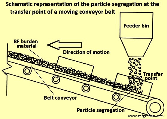
Fig 6 Schematic representation of the particle segregation at the transfer point of a moving conveyor belt
It has been established that there are four main mechanisms to be considered in conveyor belt material movement segregation namely (i) percolation, (ii) particle migration, (iii) trajectory, and (iv) free surface segregation.
Material bins and weigh-hoppers particles behaviour
Granular material bins and weigh hoppers are often used for storage and eventual discharge of material to the subsequent process step. They both in principle have (i) a form of defined material feeding or filling mechanism, (ii) some retention time of material, and (iii) a defined discharge region below. All the three steps have a contribution to the overall material flow behaviour at discharge. Physical and numerical simulations have been done to clarify the relevant information about particle segregation in different kind of hoppers namely cylindrical, bins, conical, and wedge-shaped. The desirable operation is a proportionate outflow from these devices. However, since the flow is gravity induced, the outflow is not easily controlled and there are an inherent induced shear and dynamic effects which cause segregation.
The main prevalent mechanisms of segregation in material storage bins and hoppers are free surface (during feeding), percolation (during retention) and trajectory (during discharging). There is also the importance of particle size and boundary geometry dimensions during the emptying and discharge phases.
In a study to investigate how the internal angle of hoppers affect the granular flow, it has been identified some significant hindrance to free-flow for cohesion-less solids using digital particle image velocimetry (PIV) measurements. As a rule of thumb, to avoid mechanical arching (particle interlocking), the ratio Do/dp (max) is to be satisfied in the range of 5 to 10. Here Do is the boundary outlet diameter and dp (max) is a suitable maximum particle diameter. The ratio is the dimensionless characteristic scale number and it is mostly influenced by the angle of repose as well as the particle size distribution of the material.
In another study, it has been suggested that at least eight elements are to fit across the total width of any granular material handling devices in order to capture accurately the material flow rheology. This means that the diameter of the largest particle fractions in physical or theoretical experimentation is to be at most an eighth the width of a hopper, conveyor belt or any other granular material handling device outlet.
Chute flow particles behaviour
Granular material chute flow is a common feature of stock-house and BLT charging system. With the BLT charging system which comprises of the charge receiving system, material hoppers and rotating chute (distributor), chute flow has assumed additional importance. However, the core principles of the chute flow in the BF top charging system are the same as the one in the stock-house.
Chute flow can be characterized by defining three steps which are (i) burden movement before the chute, (ii) on the chute, and (iii) after the chute, as shown schematically in Fig 7. These three steps constitute three different flow classifications and as such, different considerations need to be employed to study the flow behaviour in this system. When considering burden movement before the chute, any particle collisions in this region can be ignored due to the dilute nature of the flow. When burden material is on the chute, a mathematical description can be used with velocity component along the chute being used as the initial velocity of the material flow. At the chute tip, the trajectory of the materials determines the impact point which in turn the final scatter and distribution of the material in the subsequent handling boundary/ equipment. It is possible that the mechanisms of segregation postulated for conveyor belts systems also apply to chute flow as such and segregation shown schematically in Fig 7 is possible. Three flow streams can be identified with the core flow sandwiched between lower and surface flow. At this stage, the main force considered is gravity.
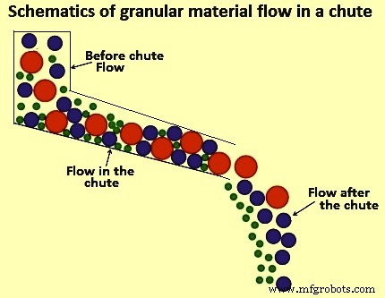
Fig 7 Schematic of granular material flow in a chute
The knowledge of segregation associated with charge material is useful for understanding the charge proportioning in addressing one of the aspects of BF process intensification. However, process intensification in BF processing requires an optimized charging system capacity as BF productivity can be limited by the capacity of stock-house to supply the charge. There is a need to address and optimize multiple-handling operation stages in the product chain.
Charging system capacity analysis
The operation of the BF charging system is as critical as the design of the BF. As can be seen in the schematic representation of a typical modern BF charging system equipped with a conveyor belt delivery system in Fig 8, the material flow sequence is quite complex.
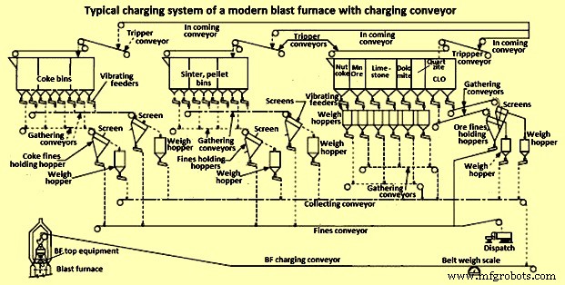
Fig 8 Typical charging system of a modern blast furnace with charging conveyor
In the interest of high productivity, the design of a BF charging system require attention to operating flexibility, availability of extra charging capability, high screening efficiency as well as a limited number of filling, discharge and transfer operations as these cause segregation problems. One important route to increase the efficiency of the BF is full utilization of the charging system capability. Further to this, if the stock-house is not adequately designed and optimal burden delivery is not achieved, the starvation of the BF take place due to the non-availability of the burden materials which consequently results into the loss of BF productivity.
As seen in Fig 8, there are numerous unit operations in a stock-house assembly and all of them have a cascading effect on the overall performance and output delivery to the BLT charging system. In order to understand the macro-behaviour of the burden movement and overall system performance, effective and comprehensive representation of salient system elements and their relationships are to be established. Technically, this involves a description of the various handling steps, materials requirements, duration and sequencing of operations. However, for complex systems such as the stock-house, it is a huge task to clarify all the unit process information. A blend of engineering judgement, experience from similar processes, and reasonable assumptions are used for model development input data and the stock house design.
Modelling of BF charging system optimization
BF charging system involves multiple-handling material movement. The major challenge associated with multiple-handling during materials movement is the timely fulfilling of the requirement and sudden change in the process. Simulations are often used to optimize materials handling systems. Such systems generally use computer-aided process design simulators. These simulators are generally designed to model transient and continuous processes and as such they cannot be used for BF charging system operations which is a batch and semi-continuous process at best. Two available options for modelling batch and semi-continuous processes like BF charging system are spreadsheets (Microsoft Excel) and discrete event simulation (DES).
Spreadsheet models are a common platform that focuses on material balances, equipment sizing and cost analysis. Typically, the development of such a model involves writing an extensive code (in the form of macros and subroutines) in visual basic for applications (VBA) which are incorporated in Microsoft Excel. They are easy to build, much applicable to simple systems but they lack robustness and become unwieldy for large and complex systems. DES is a mathematical/ logical model of a physical system which portrays state changes at precise points in simulated time. Both, the nature of the state change and the time at which the change occurs, mandate precise description. The main feature for a successful DES is an upfront requirement of precise details regarding system and interruptions. Typically, a DES can statistically account for downtime and events. Also, modules can be created and reused while multiple grades or change in process input can be easily handled. Hence, generally the DES-based model is normally used for the BF charging system.
Cyclograms analysis is a modest DES modelling technique which has been often used in BF charging systems for its optimization. The concept evolves on the minimization function of overall start – end sequence (delivery time) of a charging cycle. The delivery time is determined by the order of activation of the mechanisms, the duration of their sequence and the length of the intervals between individual operations. It is easy to follow that the minimum cycle duration occurs when the system is devoid of pauses between the operating cycles of individual mechanisms, as well as when the mechanisms are activated in an efficient sequence.
With cyclograms analysis, it is difficult to incorporate real-time changes in system input conditions. Furthermore, the structure of the analysis precludes detailed in-cooperation of micro-system variables such as discharge behaviour and segregation tendency of materials. Due to these weaknesses of the cyclograms analysis, a DES charge material delivery model based on a mathematical/ logical representation is the better choice for the BF stock house optimization
制造工艺