

高炉过程自动化、测量和控制系统
高炉过程自动化、测量和控制系统
现代高炉的高效运行需要高度自动化以及测量系统和监控系统。高炉过程控制系统与高炉优化系统相结合,打造智能化高炉自动化高水平。复杂模型与专家系统之间的最佳交互为工厂操作员提供了全面的帮助,并将人为错误的风险降至最低。
与高炉过程自动化、测量和控制系统相关的问题包括过程控制中的线性和非线性、单变量和多变量系统的经典控制理论问题,以及操作和生产控制问题。为此,将应用复杂的操作系统。这些系统必须在没有操作员的情况下自动启动和停止特殊程序模块(“任务”),以便满足所谓的“实时条件”,计算机必须在明确定义的最长时间(截止日期)内完全做出反应过程中的一个事件。截止日期从几分钟到几秒钟不等。
高炉过程自动化、测量和控制系统是高炉成功运行的主要贡献者之一,属于其经济效益的关键因素。高炉工艺的复杂性,加上对效率和减少环境影响的需求不断增长,需要改变工艺控制策略。过去,基于黑盒原理的静态计算用于预先确定一些基本设定点,但过程反馈有限。只有当过程与静止操作点的偏差很小时,这种类型的控制才能给出可接受的结果。由于过程不稳定性,小扰动可能会导致与通常使用 AI(人工智能)方法的设置点校正的操作点有相当大的偏差。
随着装料成分和各种操作实践的变化,过程的动态性将被考虑在内,以提供设定点的重新计算和实时的即时反馈。动态过程控制的一个先决条件是传感器和测量技术的发展,它可以提供有关过程状态的实时信息。动态模型的评估使得从过程监督到主动实时控制成为可能。不同的方法反映了具体的情况和控制理念。目前高炉过程控制系统是基于动态模型并允许在线控制的。基本方法是将高炉视为一个包括水冷的系统,在该系统中提供材料和能量,发生放热和吸热化学反应,能量以热损失到水冷表面的形式消散,并作为显热消散。气体。
成本优化操作、不影响炉料选择的工艺改进、最高的产品质量以及实现和保持所需的生产力是先进高炉工艺自动化、测量和控制系统的核心挑战。具有精确化学目标的优化负荷计算和随后的闭环控制构成了生产高质量铁水和炉渣的基础,同时降低了能源消耗。优化系统可轻松访问所有工艺参数、材料特性和生产率数据,包括装料信息、化学和物理负荷材料以及工艺测量,以便确定以最佳质量水平生产铁水和炉渣的最佳条件.
高炉过程自动化、测量和控制系统是一种高精度的过程控制,具有即时的在线图形信息。它为高炉提供稳定、可重复的操作,并具有恒定的铁水质量。它确保了独立于班次的工厂操作,其中手动交互减少到最低限度。结果是高炉始终平稳运行,延长了设备寿命,降低了生产成本。图1为高炉过程自动化、测量与控制系统概况。
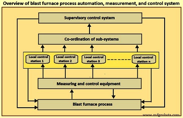
图1高炉过程自动化、测量和控制系统概述
高炉过程自动化、测量和控制系统的优势包括 (i) 高生产率,这意味着将高炉的运行保持在最佳性能,同时最大限度地减少电能和燃料的消耗,(ii) 高且均匀的产品质量,是指将铁水和炉渣的化学性质保持在所需水平, (iii) 根据高炉的热条件,通过对燃料速率的小幅修改,降低燃料消耗,同时保持铁水温度恒定,( iv) 全天稳定、独立和最佳实践的高炉操作,以确保高效生产,(v) 轻松集成各种冶金模型和软件包与自动化、测量和控制系统,(vi)对需求变化做出快速灵活的反应,(vii) 未来系统扩展的可能性,以及 (viii) 非常快速的 i 回报投资。
高炉过程自动化、测量和控制通常由一级自动化的 PLC(可编程逻辑控制器)和 HMI(人机界面)系统组成,它们是所有关键过程的控制。这些控制手段由二级解决方案(工艺模型、专家系统和程序工具)完成,涵盖整个高炉操作或炼铁过程的特定部分(热风炉、高炉装料等)。专家系统用于高炉的集成 Level-2 解决方案。这种先进的工艺辅助系统包括高炉控制和实时数据分析和工艺优化以及延迟高炉数据分析。它允许操作员优化铁水生产,并得到基于知识的系统的帮助,并报告性能指标和生产数据。
在整个过程自动化、测量和控制系统中,使用计算机、可编程控制器和微控制器,它们以局域网的形式连接,以执行从企业级到工厂的所有通信,反之亦然。最优方式。智能电机控制系统与控制系统集成在一起,为提高诊断和现场设备性能提供分布式控制和额外的维护数据。
高炉过程自动化、测量和控制系统具有 (i) 高速、开放和冗余的网络,(ii) 完整的现场 I/O(输入/输出)布线和设计考虑,以降低安装成本,(iii)作为最低要求,在控制系统中具有 HART 接口功能的 HART(高速公路可寻址远程传感器协议)仪表,(iv) 能够维护包括控制系统在内的所有工厂资产的资产管理系统,(v) 与 2 级应用程序的无缝接口过程优化(如果尚未在级别 1 中执行)和级别 2 的历史数据可以通过级别 1 控制平台轻松增长,(vi) 级别 0/1 数据存储在历史文件中,用于 HMI 或在2/3 级,(vi) 过程和操作报告,以及 (vii) 操作员和维护数据/诊断系统。 HART 通信协议是混合模拟+数字工业自动化开放协议。它最显着的优势是它可以通过传统的 4–20 mA 模拟仪表电流回路进行通信,共享仅模拟主机系统使用的一对电线。
典型的高炉自动化系统使用过程控制器、集成在高速“Modbus plus”对等网络中的操作站。这导致具有即时在线图形信息的高精度过程控制。主要是热风炉和炉料优化,通过万无一失的联锁装置实现可靠和安全的高炉装料和炉料分配,确保高炉稳定、可重复地运行,铁水质量稳定
由于高炉是一个非常简单的反应容器,因此很难直接而精细地控制其中的条件。此外,由于高炉工艺变化非常缓慢,一旦扰乱了高炉的稳定运行,就很难恢复到正常状态。因此,为了保持稳定的运行,有必要监测炉内条件的微小变化并及时采取适当的措施。为此,过程计算机收集并计算来自设置在高炉各个位置的传感器的数据,从而实时监控高炉的状况。当检测到任何可能对高炉稳定运行产生不利影响的变化时,它会为高炉操作人员输出行动指导。
更具体地说,高炉过程控制系统的监控功能包括(i)通过计算铁矿石和焦炭的装料比及其装料的顺序来控制矿石和焦炭的装料,(ii)通过设置旋转装料溜槽的运行模式进行装料运行控制,以实现矿石和焦炭的充分周向分布, (iii) 通过控制热风炉内的燃烧控制热风炉,从而稳定地供应热风,(iv)通过基于来自各种传感器的信息估计炉内状况来控制炉子,以及(v)通过控制出钢量和质量来控制铁水和液态渣的出钢。如图所示综上所述,高炉过程自动化、测控系统在高炉运行中具有十分重要的作用。
现在的高炉安装了近千个传感器。传统模拟仪器中的大量传感器难以安装在广阔的炼铁区域中。微电子和数据通信系统(如数据高速公路)的进步使得引入分布式数字仪器成为可能。与传统的模拟仪器相比,数字仪器有几个优点,例如(i)能够构建无噪声系统,尤其是电磁噪声,(ii)能够使用先进的信号处理和先进的控制功能,(iii)系统的可靠性可以通过使用双重功能进行改进,(iv) 通过使用 CRT(阴极射线管)显示器,可以从紧凑的控制台接收比以前巨大的模拟仪表板更多的信息,(v) 更容易改变或改进系统或功能,(vi)更容易与主机系统交换信息,以及(vii)从增加功能的角度来看,安装成本比传统的模拟仪器便宜得多。由于这些原因,高炉过程自动化、测量和控制系统通常采用数字化仪表。
高效的高炉控制需要可靠地测量炉内条件。炉子下半部分的温度可升至 2,000 摄氏度以上,此时大多数侵入式测量技术都不可靠,因此大多数炉内测量都在炉料表面上方或附近进行。可靠的探头操作对于定期支持数据处理、熔炉工艺模型和熔炉操作监控系统非常重要。可靠的探头可帮助高炉操作员建立 (i) 炉顶煤气温度分布和炉顶煤气化学成分,(ii) 材料下落轨迹、料线水平和分布,(iii) 炉料层堆积、混合和下降行为,( iv) 配料塔中的气体和温度分布,(v) 滚道和焦炭床条件,以及 (vi) 铁水质量和出钢操作。直接或间接量化负载分布的最重要技术包括 (i) 负载上探头,(ii) 负载内探头,(iii) 库存线检测器,(iv) 剖面仪,(v) 垂直探头, (vi) 热电偶,(vii) 炉壁上的压力表,以及 (viii) 其他测量。图2为高炉部分探头的典型布局。
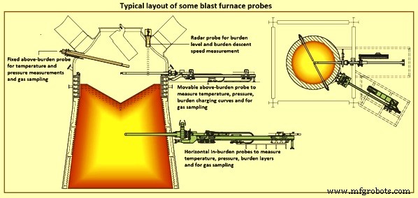
图2部分高炉探头的典型布局
超载探测 – 上述负载探头有许多连接到设备上的热电偶,用于测量负载表面上方不同径向位置的气体温度。这提供了有关炉内气流条件的信息。与具有较高渗透率的区域相比,具有较低渗透率的区域允许较少的气体流动,这降低了气体温度。因此,温度读数提供了有关炉内渗透性条件的信息。
上述负载探针的一个问题是从负载表面出来的气体在到达探针之前会混合。因此,某些温度可能被低估或高估。因此,探头应安装在更靠近料面的位置,这很难实现,因为料面在工艺过程中会随着生产率而变化。此外,流化引起的库存线突然增加会损坏探头。
负载内探测 – 负载内探头通常安装在负载表面下方和粘性区域上方的任何高度。因此,与上述负载探头相比,这些探头必须承受更高的温度和磨损。这就是为什么它们通常是可伸缩的并且仅在采样完成时插入的原因。负载内探头测量不同径向点的气体温度和成分。通常,测量结果比来自上述负载探头的信号更准确,因为混合不会以相同的程度发生。但是,严格来说,结果取决于测量时采样点所在的层。
库存线检测器 – 料线检测器用于在将每个垃圾装入熔炉后获取有关料面高度的信息,称为“料线”。高炉经过编程,只有当料面下降超过某个垂直高度时,才会将倾卸料装入炉内。料线检测器可以是机械装置(料棒),其中链或线末端的重量被降低,直到达到负载表面形式的阻力。目前的熔炉使用非接触式技术,例如雷达系统,可消除时间损失,同时降低进入熔炉的重量。库存线的突然下降表明出现滑坡,这可能是熔炉操作员担心的问题。
个人资料仪表 – 轮廓仪最初是机械设备,但现在已被非接触式方法所取代,例如沿水平通道的可移动雷达(移动探头)测量各个径向点的负载表面高度。轮廓仪还可以估计负载下降速度。目前的剖面仪将雷达固定在旋转接头上,并且可以估计 3D 负载表面,这比沿单个方向的测量提供了更好的理解。在高炉中使用雷达进行非接触式液位测量具有几个优点,包括 (i) 可靠的测量,不受灰尘、材料成分和高温的影响,(ii) 即使在填充过程中也具有很高的测量确定性,以及 (iii) 磨损和免维护操作。
垂直探头 – 垂直探头用于沿高炉高度提供温度和气体成分。这些探头可以由位于不同径向位置的电缆组成,这些电缆降低到炉料表面并被移动的固体拖下,直到尖端损坏,因为电缆在炉子的下部达到高温。探头通常测量温度和压力,并可以对气体进行成分采样。这些探头可以配备用于粒度分布的摄像头。腐蚀探针的长度也表明了熔炉内粘合区的位置。尽管垂直探头可以提供有关熔炉的最大信息,但由于价格昂贵且需要复杂的进料设备,因此很少使用。
热电偶 – 高炉壁内衬有热电偶,这些热电偶还提供有关高炉操作的重要信息。例如,热电偶读数的突然变化可能表明颅骨下降,这是在炉壁上形成的停滞凝固块。
由于尖端材料的污染和迁移,炉子中遇到的高温和高压导致的恶劣环境大大缩短了热电偶的使用寿命。用于保护传统热电偶的金属护套在 1,200 摄氏度以上是不可行的。替代护套很容易因加热循环期间陶瓷砖砌体的膨胀和收缩而破裂或损坏。此外,突然的压力释放(或“吸食”)会导致温度读数下降 20 摄氏度至 30 摄氏度,持续约 30 秒。这使得热电偶信号不适用于自动炉反转控制系统。正确安装的红外高温计系统可为炉灶应用提供准确的温度测量,同时克服了使用热电偶时遇到的几个问题。
炉壁上的压力表 – 在墙壁上的不同点测量气体压力。当气体流过焦炭缝时,方向是水平的,因此它会影响壁上的压力。因此,压力信息可以用来估计粘聚带的形状。
其他测量 – 高炉的其他一些测量包括 (i) 炉顶煤气的压力、温度和成分,(ii) 冷却水的流速和温度升高,(iii) 鼓风条件,(iv) 铁水和炉渣变量,(v) 使用腹部探头等。 (vi) 红外摄像机测量负载表面温度,和 (vii) 皮肤流动热电偶(或微型探头)。这些测量值间接受到负担分布的影响。
高炉中使用的一些附加测量探头是 (i) 材料扫描探头 (ii) 风口探头,(iii) 岩芯取样器,(iv) 冲击探头 (v) 鱼雷钢包液位雷达探头,和 (vi)炉壳内电阻测量。
高炉优化的核心功能
高炉优化是一种创新的工艺优化系统,它将高炉工艺自动化、测量和控制系统提升到一个全新的水平。基于经过充分测试和验证的基础系统的典型解决方案可确保最高可用性并有效地结合数据采集、处理和可视化。该系统展示了可靠性和成本节约。
广泛的原始数据源(包括前端信号、装料量、实验室数据、事件、模型结果和成本数据)在整个工厂生命周期中存储。提供了允许将过程信息链接到分析数据和负担矩阵的专用工具。灵活的接口、模块化和可靠的软件架构提供了在不断变化的原材料、运营理念和与第三方系统连接的环境中轻松适应和维护系统的方法。
除了强大的基础系统之外,许多交互过程模型支持操作员和直线经理的日常决策。冶金过程模型使高炉过程变得透明。工厂的具体要求通常包含在这些冶金过程模型中。
动态模型的目的是持续显示和预测过程状态。它还允许使用适用的工艺策略控制各种工艺参数。过程状态确定基于从现场仪器检索到的信息。已开发的模型的一些示例是(i)材料分布和特定材料区域的位置,(ii)气体分布,(iii)温度分布,(iv)熔炉及其部件的热状态,(v) ) 下降区的铁水和炉渣化学成分,(vi) 炉缸液位,(vii) 材料区的几何形状(粘性区、下降区、死角和长期热阻),以及 (viii) 竖井几何形状(脚手架)。开发的模型具有分析、经验和启发式的性质。计算循环运行,这些模型的输出是炉子的几何、热和材料状态及其特性。
预测模型根据熔炉输入的实际数据进行实时模拟。模型为带状。建模过程是气体流动、物质流动、热过程、化学过程、物理过程和几何过程。炉状态由热量和材料平衡的每个元素确定。该计算基于从实验室和现场仪器检索到的信息,允许关闭天平。模型中使用了基本的化学反应。
通过最新的数据可视化和冶金工艺模型实时实现端到端的透明性,从而实现更好的协作、改进工作流程并减少错误,同时也支持决策制定。即使是火焰温度和间接还原百分比等重要的工艺参数也采用软传感器实现,这使得它们与常规测量无法区分。
钢铁行业的信息技术正在发生变化,预计移动访问将超过基于桌面的访问。 HMI 的设计应具有响应性和灵活性,无论是桌面还是新的多点触控界面。简单易行,让操作者工作更有效率。
通过结合使用不同的测量方法和过去的经验,操作员可以全面了解高炉的状况,并确定不正确的高炉状况的原因。下面简要介绍高炉不同区域的过程自动化、测量和控制。
库房和装炉自动化 – 从秤车系统到全自动输送机/筛网/给料系统,可以实现仓库和炉子装料的自动化,将矿石焦炭和杂料提供给跳过式或带式给料炉。这包括远程创建批处理配方的能力,或通过具有全自动“充电主”程序的人机界面创建批处理配方的能力。该程序跟踪从仓库存储箱到运送到炉顶的物料流,完成干重误差校正和重量误差补偿,以保持正确的炉料成分和水平。全自动系统的一个重要组成部分是增加一个除尘系统,以去除和提取材料处理过程中产生的排放物。
基于材料的装料系统允许将不同的材料动态分配到仓库掩体。收费矩阵仅与可用材料有关,与掩体无关。效果是更灵活的工厂操作,无需程序调整。或者,也可以使用传统的基于掩体的充电矩阵的更精细版本。与装料矩阵的类型无关,对剂量偏差的智能补偿被认为是理所当然的事情。在带式进料炉的情况下,库房控制计算物料在装料传送带上重叠的所有可能性。配合从库房到炉顶的全面物料跟踪功能,实现了平稳高效的运行。
炉顶装料自动化 – 炉顶装料自动化包括 (i) 小钟罩/大钟罩材料输送的控制系统编程以及无钟罩系统的控制,(ii) 库存线液位监测和控制,(iii) 炉顶加压和泄压系统,(iv) 润滑系统,(v) 至少,在控制系统中具有 HART 接口功能的 HART 仪表,以及 (vi) 用于控制炉顶泄压泄放阀的安全设计,包括相关的液压系统。
不同的充电设备对充电过程提供不同程度的控制,最终决定了负荷分配。不过,即使有几个选项,充电过程也会变得非常复杂,有时可能会违反直觉。
对于所有标准类型的物料分配系统,智能分配解决方案通常在无钟顶装料的情况下提供。通过启用螺旋装料、满环以及重量或时间分布的选项改进了最常见环分布逻辑的智能版本。因此,单个批次之间的灵活和边际分布修改是可能的。点装和分段装料提供了一个灵活而简单的机会,可以在苛刻的高炉条件下对实际炉况做出反应。平滑的自由形状分布是环形分布和点分布的组合,将速度变化应用于分布装置。这种模式结合了稳定的环模式分布和自由形状分布的灵活性。
闭环炉料分配控制是高炉工艺稳定和降低燃料消耗的自动化系统的独特功能。基于高炉竖井的径向温度测量,该模型计算分布模式的修改,以实现目标温度曲线。该系统支持基于常规和声学技术的负载内探头或负载上温度测量。
炉体和炉膛自动化 – 炉体和炉膛的自动化包括过程温度监控、趋势和警报、废气分析以及负载上和负载内探头系统的控制。作为监控系统的一部分,过程和生产计算以及第三方模型用于提供操作指南。其中一些数据包括(i)炉膛和侧壁等温线,(ii)炉料分布,(iii)磨煤和煤粉喷射,(iv)风口泄漏检测和热损失,(v)过程计算,如绝热火焰温度,渗透率和风口速度,以及 (vi) 进出 2 级系统的数据(历史数据文件和过程模型)。
优化的高炉操作需要准确装入原材料,包括烧结矿、球团矿、矿石、焦炭、熔剂和添加剂。在修改装料设定点时,应考虑焦化率、炉渣碱度和实际原料分析以及它们对高炉参数的影响。这个过程很复杂,需要计算机模型的帮助。负荷控制模型基于优化的炉料组成计算装料矩阵,炉料分配模型通过精确的物料分配提高气体利用率。
借助高炉优化系统,操作员在整个过程中拥有完全的数据透明度。通过系统生成的简明报告,这些种类繁多的流程和元数据(例如班次、警报和材料)变得透明、可访问和易于理解。智能瓷砖用作玻璃门,即使应用程序未运行,也会自动显示来自操作员最喜欢的应用程序的实时信息。如果与正常工艺参数有显着偏差,主屏幕上会显示相关的生产数据,使操作员能够做出重要决策并针对情况采取纠正措施。
炉料控制模型的目的是建立精确的炉料组成,以满足焦炭和燃料喷射率、炉渣碱度、铁水质量和炉料进料速度的指定目标值。负担控制模型的最终结果是一个计费矩阵,只需单击鼠标即可将其传输到基本自动化系统执行。结合专家系统,炉料控制模型是高炉操作全自动炉料成分优化的核心部分。
炉料控制模型的好处包括 (i) 稳定的产品质量,这意味着将铁水和炉渣的化学成分保持在所需的水平,(ii) 与班次无关的炉料修改,因为新炉料成分的计算是使用自动执行的最新的原材料分析和标准化的计算程序,以及 (iii) 计算和激活新的计费矩阵无需手动操作员交互。
无钟形装料溜槽以及带可移动装甲的钟形装料装置能够将矿石和焦炭层精确分布到高炉中。配料分配模型帮助操作员和/或生产线管理人员根据实际工艺要求修改实际分布,以改善气流模式和配料渗透率。该模型通过高炉竖井模拟炉料下降,并计算竖井上部材料层的实际形状。 It also computes the radial volume, chemical properties, and particle size distribution, taking into account material segregation.
The on-line burden distribution model performs the calculation based on actual charging data and actual measurements of the stock-line and calculates the current burden distribution in the upper shaft of the furnace. This gives the operator the opportunity to detect irregularities in the burden distribution in a timely manner. In the off-line mode, the model calculation is based on a charging matrix and a pre-defined stock-line. The off-line burden distribution model is a valuable tool for the design of new distribution matrices for optimized gas-flow patterns and burden permeability.
3D hearth lining monitoring – 3D hearth lining monitoring is for safe, durable, reliable production at the blast furnace. The campaign duration of a blast furnace is mainly determined by the lifetime of its hearth. Hence, it is clear that monitoring the refractory thickness in the hearth wall and bottom areas is important for estimating the lifetime of the hearth lining.
The hearth wear model includes mathematical algorithms which solve the inverse heat transfer problem in 3 spatial dimensions based on the statistical evaluations of the thermocouple measurements and the heat conductivities of the refractories. The model calculates the erosion profile and the formation of the solidified skull layer. The computed wear velocity together with the remaining wall thickness allows the blast furnace operators and line managers to predict the lifetime of the hearth refractory.
The 3D hearth lining monitoring model includes user interfaces and reports for visualizing the results of the model over the entire life of the blast furnace. For every calculation, the HMI screens show 3D graphs of the actual and maximum wear lines. This means that the contour can be efficiently compared with the original lining, a single isothermal area with configurable temperature (e.g. 1,150 deg C) can be displayed, and horizontal and vertical angle ranges can be selected.
Thermal index calculation model – The energy consumption and productivity of the blast furnace are reflected by the thermal index, which can subsequently be used to predict the development of the hot metal temperature and silicon content. The model result is used as an input to the blast furnace expert system for controlling the thermal state of the blast furnace process.
Shaft calculation model – The model performs a mass-balance calculation based on actual charging data using the materials of one charge, consisting of one coke and one burden layer. These individual charges are tracked from the furnace top down to the tuyere area. The results are displayed graphically and allow the operator to track burden composition and burden distribution changes. The model also computes the time when burden changes become effective on hot metal and slag.
Mass and energy balance plausibility model – This model automatically generates reports based on actual charging, process, and production data over a pre-defined time period, taking into account the material retention time in the blast furnace. The mass and energy balance calculation is used to detect the build up of alkaline and zinc circuits or to identify systematic measurement inaccuracies. The subsequent balance plausibility algorithm indicates the most probable sources of measurement faults.
Automation of cast house – Stable and reproducible tapping operations are necessary for both the hot metal quality and the establishment of a smooth, efficient blast furnace process. Further, a clean and safe working environment in the cast house is achievable with good layout, accessibility and ergonomics. The cast house machines are to work together to provide this environment. Cast house automation provides for consistent, safe, operation of the cast house. It includes (i) control of mud gun and tap hole drill equipment, (ii) trough and runner temperature monitoring, (iii) tilting runner operation and monitoring of the level of hot metal in the ladle, (iv) process parameters of slag granulation, (v) monitoring of the cast house fume collection systems, and (vi) control schemes include radio operated belly box designs to fully automated gun-up and automated drilling logic.
The tapping management model calculates the actual hot metal and slag production rates as well as the drainage rates through the open tap holes. This allows it to continuously compute the actual amount and level of hot metal and slag in the hearth. The model result is used as an input to the blast furnace expert system, which makes a recommendation on opening a tap hole.
Automation of furnace cooling system – From shell plate spray cooling to closed loop stave cooling, the various options for furnace cooling and temperature monitoring and control are managed through a well instrumented and integrated control system. Heat flux monitoring and water treatment systems are integral to proper furnace cooling operations and longevity.
Leakage detection system for critical cooling circuits – Leakage detection system is essential from the point of view of safety. There is risk involved if there is no quick detection of the leakages. Expanding cracks or small water leaks in cooling system pipes can affect the quality of hot metal, lead to stoppage of production, damage to furnace, or in the worst case, loss of life.
A system which effectively detects leakage is hence not just one of the most important parts of the blast furnace process automation and control system, but more importantly, an integral part of the at the blast furnace. For this reason, the leakage detection is designed so as to meet the requirements of the safety standard for the instrumented systems for process industries sector.
Automation of stoves and hot blast delivery – Stove automation is for providing automatic cycling of stove valves to supply uninterrupted and consistent hot blast to the blast furnace. Stove cycling systems is designed for 2, 3, and 4 stove operation. Stove automation includes control of the process gasses and firing strategies, including Level 1 control optimization, and burner management capabilities. In addition, preheated air and gas supplies are used to reduce the amount of enrichment gas used in the stove heating cycle. Cold blast monitoring and control and hot blast temperature control, fuel injection control is included within the hot blast delivery system.
Present day blast furnaces are typically operated very close to the maximum hot blast temperature which the stoves can sustain. If the dome temperature does not increase rapidly enough, sophisticated controls are provided to enrich the blast furnace gas with a fuel of higher calorific value to achieve a faster heating rate. The use of the optimized combustion control consists of a number of features such as (i) control of excess air, (ii) consideration of flue gas oxygen or chemical combustibles analysis, or both, (iii) dome temperature influences on the gas enrichment ratio, and (iv) sequencing for either three or four stoves.
Optimization of hot stove is needed for achieving high efficiency, flexibility, and energy saving. The blast heating process offers considerable energy saving potentials. The challenge for the plant operators and the line managers is to optimize the energy input to the hot blast stoves while keeping the blast temperature at given targets of the blast flow rate and the blast time. The stove model ensures stoves optimization, and energy savings by increasing stove efficiency.
The hot stoves control model combines short term direct control and longer self-tuning algorithms. Rapid control is used to correct the firing rate for maintaining the proper stoves operation parameters. The fast controls reduce carbon di-oxide (CO2) emissions and maximize stove efficiency. Artificial intelligence algorithms are used to optimize the efficiency performance of the hot blast stoves. These self-learning algorithms enable operators to identify and correct measurement errors.
The hot blast stoves control model supports all operation modes in combination with various rich gas types. All the types of stoves (such as Cowper or Kalugin) as well as pre-heating and heat-recovery systems are normally covered in the model.
Automation of gas cleaning plant – Blast furnace gas is cleaned using a variety of methods including a cyclone or dust catcher to remove large particles and either annular gap water sprays or electrostatic precipitators. Semi-cleaned gas has also been used to drive a TRT (top gas recovery turbine) system for energy recovery. In either case, gas cleaning systems provide furnace top pressure control, as well as cleaned gas to be re-used for various processes including stove heating, and for use in the boiler house of the power plant.
Closed loop blast furnace expert system
The closed-loop blast furnace expert system is normally designed according to the principle ‘as few actions as possible, as many as essential’. The objective is to optimize blast furnace operation and reduce operator interactions to a minimum. The expert system, which is normally designed as a rule-based decision system, counteracts process fluctuations caused by changes in burden material composition and quality, human factors, and process conditions. The sooner the system responds to an abnormal or changing process situation, the smoother is the overall blast furnace operation. Timing control activities accurately and anticipating disturbances are both of the utmost importance in order to avoid critical process conditions and to maintain a high production rate at low costs. The closed-loop blast furnace expert system ensures considerable improvements to product quality and reduced fuel consumption with the available burden materials.
The expert system recommends operational changes in a two-step process. The first step is an analysis of the current situation, called process diagnosis. The expert system studies the occurrence of phenomena in the blast furnace using a variety of technical calculations based on a huge amount of process measurements and analysis data which are collected continuously. In the second step, corrective actions are proposed if needed. An extensive rule set forged by experienced blast furnace process experts and operators on the basis of cause-and-cure relationships results in recommendations for the best-practice and shift independent operation. Corrective actions to achieve and maintain the smooth operation of the blast furnace are reported to the operators. The actions can be executed either in closed-loop mode or after operator confirmation.
There are a set of major corrective actions which results in a continuous, shift-independent blast furnace operation. The guidance of the expert system, especially during start-up and shut-down periods, leads to energy savings and minimized production losses. This uniform operation contributes to prolonging the lifetime of the blast furnace. The set of major corrective actions are described below.
Fuel rate and injection control – The expert system observes the thermal state of the blast furnace hearth and suggests a change of the fuel rate as soon as significant deviations from optimal conditions are recognized. According to the rules defined in the knowledge base, either a change of injected fuel or coke rate is suggested and can be executed fully automatically.
Slag basicity control – On the basis of recent slag analyses and hot metal temperature data, the expert system recommends changes in the burden composition as soon as a deviation from the target slag basicity is detected. Working with the burden control model, a new charging matrix is calculated automatically which can be transferred to the process control system for execution.
Control of oxygen enrichment and steam addition – The oxygen enrichment control calculates an optimized oxygen addition rate to achieve the target hot metal production. Critical situations caused by rapidly increasing production rates can be avoided. The expert system uses steam addition to maintain the burden permeability at the targeted level. Because of the fast control cycles, it is possible to precisely adjust the addition of steam to the amount needed by the process. In this way the steam input is reduced whenever possible directly leading to energy-savings.
制造工艺