

了解日本高炉炼铁和解剖研究
了解日本高炉炼铁和解剖研究
高炉 (BF) 炼铁是生产铁水 (HM) 最可行的方法,主要是由于其成熟且经过验证的性能、灵活的原材料使用和高热能节约能力。高炉炼铁的开始没有确定的日期。然而,早在 14 世纪,欧洲的炼铁炉就开始实施重要的工艺设计和重新设计。从那时起,高炉路线作为一种优先于其他替代铁生产方法的过程占据主导地位。
自成立以来,高炉炼铁工艺为了维持并保持可行性,经历了持久的进化发展,成为一种高效的工艺。迄今为止最重要的发展包括 (i) 设施现代化,(ii) 提高熔炉生产率,(iii) 降低焦炭率,(iv) 延长熔炉运行寿命,以及 (v) 材料灵活性和改进。为提高经济性、效率和使工艺环保而进行的技术进步包括 (i) 各种工艺管理和控制实践,(ii) 中心焦炭装料,(iii) 高炉顶压力操作,(iv ) 富氧 (O2) 炉操作,(v) 用替代补充碳源(即粉煤、天然气、油和塑料)替代昂贵的焦炭,以及 (vi) 更多。 BF 炼铁工艺的技术发展使其从一个消耗大量燃料的小型生产装置发展到目前的状态,设计用于每天生产 10,000 吨 HM 的熔炉在几个国家相当普遍。即使高炉尺寸和产量大幅增加,炉内发生的许多反应仍然未知。
现代高炉主要处理烧结矿、球团矿、烧结矿/分级铁矿石或烧结矿/球团矿。这些材料的种类和质量取决于各个工厂的经营理念,因此这些材料的生产和还原特性对高炉工艺至关重要。
BF工艺的发展
高炉工艺的发展逐渐被引入,最终成为标准操作实践。可以按大致时间顺序列出主要发展,包括 (i) 有效使用准备好的炉料,(ii) 喷射喷射剂,(ii) 高顶压,(iv) 高喷射温度,以及 (v) 改进的控制的负担分配。在这些发展的同时,BF 的物理尺寸也逐渐增大。
使用准备好的负担
炉料的第一个准备工作仅仅是确定装入熔炉的铁矿石的大小。炉料的尺寸越小,炉子的透气性越好,吹的风越多,从而提高了高炉的产量。此外,由于去除了较大的矿块,还原反应的效率也提高了,从而降低了结焦率。
装料前的铁矿石烧结是炉料准备的第二个重要步骤,但最初开发烧结是为了将诸如高炉烟尘、轧屑和矿粉等废铁轴承材料转化为可用的高炉原料。然而,在 1950 年代中期自熔烧结取得成功后,这一概念迅速改变,允许从高炉装料中去除助熔剂并通过烧结矿引入。这也导致焦炭率降低,同时提高了高炉生产率。目前的情况是,烧结矿已成为现代高炉厂的一种既定的炉料成分,它仍在不断研究中,以进一步改善其性能。
容易获得的高品位铁矿石的枯竭使得供应商有必要通过选矿来升级他们的产品,然后从精矿中生产高品位铁矿石球团。这种工艺得到了广泛的认可,导致高炉炉料的铁含量高、脉石含量低,这反过来又导致产量进一步增加,同时焦炭率下降。球团声称的另一项改进是,由于更紧密的尺寸,填料的渗透性增加。然而,球团矿的使用并不普遍,在一些国家,高炉主要以烧结矿装料运行,球团矿和/或分级铁矿石仅占总装料的一小部分。确实有一些观点认为,高烧结率对于大型高炉的稳定运行至关重要,因为烧结矿具有优异的高温和更好的分布特性,因为球团容易滚动,难以控制分布。此外,由于高炉使用烧结矿,焦炉厂产生的焦粉在钢铁厂内消耗掉。
爆炸喷射剂
BF 中通常使用三种喷射剂。它们是 (i) 蒸汽、(ii) O2 和 (iii) 辅助燃料。喷射剂影响火焰温度,即风口燃烧区的火焰温度。蒸汽和辅助燃料会降低火焰温度,而 O2 会增加火焰温度。可以计算出理论火焰温度,这对于在大量氧气和辅助燃料的情况下保持平稳运行和提高生产率极为重要。低火焰温度会阻止炉内反应并导致炉内冷却。由于熔化区的扩大以及炉料中碱和二氧化硅 (SiO2) 的蒸发,高火焰温度会损害渗透性。为了保证平稳运行,需要通过改变喷射剂的用量来控制理论火焰温度。
分别看三种喷射剂,蒸汽与焦炭反应产生氢气 (H2),这增加了负载材料的减少程度,从而降低了燃料速率。辅助燃料是主要的喷射剂。使用的辅助燃料类型取决于当地条件。辅助燃料的喷射在 BF 中提供了额外量的 H2 和一氧化碳 (CO),从而增加了负荷的减少程度,进而降低了焦炭率。必须确保辅助燃料在风口处完全燃烧,因为不完全燃烧会损害炉子的透气性,对炉子的运行造成不利影响。通过在鼓风中提供足够的过量氧气可以控制燃烧不充分。
氧气喷射增加了过量氧气的量并提高了火焰温度,这抵消了由于喷射蒸汽和辅助燃料引起的火焰温度下降。它还有助于减少波什气体的量,从而最大限度地减少高炉中气体的窜流程度以及溢流和装载程度。溢流导致炉子运行不正常。加载是由于向上的气体速度阻止熔渣下降的情况。最终,炉渣的重量将足以克服气流使其下降。当鼓风中O2的比例逐渐增加时,每吨HM产生的气体量减少,导致竖井中气体向固体的传热量下降,导致炉膛温度下降。轴。此外,通过 O2 富集来提高生产率会加快负荷下降速度,从而减少传热时间。导致炉料未经充分预热就进入高温区,造成炉膛急冷,造成炉料滑挂。
使用喷射剂的实践需要仔细控制三个限制,即(i)气体和固体之间的热传递限制,(ii)理论火焰温度限制,以及(iii)辅助燃料完全燃烧的限制。控制在这些限制内可提供低燃油率和高生产率。
高顶压力
高顶压的好处是它降低了炉内的气体速度,从而允许更多的时间进行气体还原,从而导致燃料速率的降低。粉尘损失也减少了,因为较低的气体速度不足以输送较粗的粉尘颗粒。或者,可以吹更多的风,从而提高产量,同时保持炉内相同的气体速度,从而防止窜流、溢流和装载。主要缺点是为了适应不断增加的燃气压力,从炉灶到烟囱管、炉壁、炉顶、气体净化装置等整个高炉设备都需要坚固的结构,显然是昂贵的。当然,为了平衡装料系统中的气体压力并防止炉顶装料设备的磨损,仅高炉顶部就需要特殊设计。另一个缺点是高压炉顶气中的能量损失,尽管炉顶气回收涡轮机可以回收部分能量。
虽然从工程方面应用高顶压存在问题,但大型高炉的操作需要使用它来(i)降低燃料速率,以及(ii)提高高炉的生产率。
高风温
通过风口进入高炉的空气被焦炭的燃烧加热,因此,进入的空气越热,在风口区域内进一步加热所消耗的焦炭就越少。空气预热并不是什么新鲜事。事实上,一个多世纪以前,BF 炉子就已经存在。然而,直到最近才达到超过 1300 摄氏度的温度。更高温度的实现是由于对炉子设计的修改。这些修改是(i)通过改变砖的形状来增加格子的受热表面面积,(ii)使用能够承受更高温度的更高质量的耐火材料,以及(iii)提供外部燃烧室,它也增加受热表面积。
改善负担分配
控制配料的分布对于提高气体利用率和降低燃料率很重要。正确的分布对于控制高炉内聚区的形状也是必要的,从而最大限度地提高产量并最大限度地减少高炉壁处的气流,从而延长炉子的使用寿命。
随着炉子尺寸的增加,由于编译角度、密度和形状的差异,传统的装料设备无法维持在高炉内提供稳定气体分布所需的炉料分布。这些问题已通过安装可移动装甲来部分克服,以控制材料在离开装料钟时的分布。无钟顶和万向顶装料系统的开发,具有旋转溜槽,能够准确地将装料分配到炉料线上的任何位置,在很大程度上有助于解决这个问题。
铁矿石烧结矿
在许多高炉中,烧结矿是高炉炉料的主要成分。烧结矿的化学成分取决于构成炉料的其他成分。通常烧结矿的范围从熔剂(CaO/SiO2 大约 1.2)到超熔剂(CaO/SiO2 大约 1.7 到 2.2)。当大部分炉料是烧结物时,通常使用熔剂烧结物。当炉渣的其余部分本质上是酸性时,使用超熔烧结,从而平衡炉渣化学成分以提供可接受的炉渣成分。由于烧结过程的性质,烧结矿的异质性极强。
烧结矿的结构 – 与铁矿石混合的熔剂在烧结过程中发生反应,熔化并侵蚀矿石颗粒。小矿石颗粒可能发生完全团聚,但通常较大的颗粒仅受到表面侵蚀。在冷却过程中,不同相的沉淀发生在渣基体中,总体结果是远离平衡状态的相的混合物和其相取决于初始混合中组分的分离的非均质材料,例如在烧结前存在石灰颗粒的地方,形成了富含石灰的区域。总体而言,存在的相取决于添加的助熔剂的数量。自熔烧结矿主要是赤铁矿和磁铁矿,含有少量铁酸钙,由铁矿石和石灰反应生成。这里的“铁氧体”一词是指可以生产的不同种类的铁氧体的总量,这取决于反应区的碱度和矿石颗粒。随着碱度的增加,铁素体的比例增加。
在烧结过程中,铁氧体通常会被 SiO2 和 Al2O3(氧化铝)污染,产品称为 SFCA(钙和氧化铝的硅铁氧体)。 SFCA 通常符合通式“n1(Fe2O3).n2(SiO2).n3(Al2O3).5CaO”,其中 n1、n2 和 n3 之和约为 12。钙含量相当恒定,约为 15 %。实践中通常在烧结矿中发现的铁素体通常为7 Fe2O3.2SiO2.3Al2O3.5CaO和9Fe2O3.2SiO2.0.5Al2O3.5CaO。
减少烧结矿 – 烧结物中存在的铁素体的类型和数量对还原性能起着重要作用。铁氧体的还原性不是恒定的,而是因一种而异。可以看出,随着烧结体碱度的升高,铁素体的比例增加。然而,还原性并不遵循相同的趋势。在碱度范围 1.0 到 1.5 之间,由于 CaO.2Fe2O3 和 CaO.FeO.Fe2O3 型铁素体的增加,还原性提高。在 1.4 到 1.5 的碱度范围内,由于赤铁矿在烧结矿中的比例下降和 CaO.2Fe2O3 的消失以及相对不可还原的 2CaO.Fe2O3 的出现,还原性降低。由于CaO.Fe2O3和CaO.FeO.Fe2O3的出现,碱度超过1.5后再次呈现上升趋势。
铁氧体的还原行为是复杂的,因为它们要分解以发生氧化铁的还原。在还原过程中,首先将富含氧化铁的高级氧化铁和铁氧体还原,直到只剩下铁酸二钙和方晶石。然后气体按照可逆反应 2CaO.Fe2O3 + 3H2 =2CaO + 2Fe + 3H2O 攻击铁酸二钙。根据可逆反应 2CaO + 3FeO =2CaO.Fe2O3 + Fe,释放的 CaO 然后立即与方晶石反应。然后反应按照前面的方程式进行,依此类推。然而,显微照片显示,方晶石不存在于气体边界,因此两个反应之间会发生扩散过程。研究表明,在氧化物表面,铁酸二钙首先被还原。释放的铁在氧化物相中析出,钙扩散进入方晶石并与之反应,铁再析出或扩散到Fe3O4中。
铁矿石颗粒
在铁矿石球团的生产过程中,铁矿石通过破碎和去除释放的脉石材料进行选矿。通常在酸性颗粒生产中添加一些石英以改善颗粒性能。生产的大多数颗粒是酸型的,即没有任何有意大量添加助焊剂。在酸性球团的生产过程中,生球团在氧化气氛中在 1300 摄氏度左右进行烧制。这通过(i)赤铁矿晶粒的烧结,(ii)磁铁矿晶粒的氧化和随后的烧结,以及(iii)熔渣结合促进了颗粒的结合。后者是由微量脉石和膨润土熔合造成的,用于造粒过程中,以确保生球团有足够的强度。该渣相主要由石灰、二氧化硅、氧化铁和少量碱、氧化镁、氧化铝等组成。
参考CaO-SiO2-Fe2O3相图可以得到渣相化学成分的指示。需要注意的一点是,平衡图要小心使用,因为在大多数过程中,反应很少处于平衡状态,然而,这样的图是有用的工具。在烧制过程中,石英颗粒和赤铁矿之间几乎不会发生反应(如果有的话),因此酸性球团由赤铁矿、石英、渣相组成,在某些情况下,如果没有进行充分的烧制,磁铁矿来自任何球团混合物中的磁铁矿。
酸性球团用于一些高炉炉料中。负载中使用的量取决于所采用的操作实践。如果高炉完全使用酸性球团作为铁单元的来源,则熔渣形成过程所需的熔剂(石灰石和白云石)作为炉料的一部分加入高炉。
助焊剂颗粒 – 目前首选使用助焊剂颗粒。在助焊剂球团中,助焊剂被结合到球团中,因此避免了将它们单独装入熔炉的必要性。可通过添加石灰、作为助熔剂或白云石来生产助熔颗粒。随着助焊剂的加入,颗粒的碱度增加,微观结构发生变化。考虑到石灰熔剂球团,石灰的添加对渣成分和数量有影响,赤铁矿的数量也有影响。添加石灰产生赤铁矿和石灰之间的反应产生铁酸钙CaO.Fe2O3 或2CaO.Fe2O3 的可能性,具体取决于石灰浓度。熔剂球团的烧成温度低于酸性球团,以避免形成过多的熔渣。
如果是熔剂颗粒,预计会发现赤铁矿颗粒被石灰的化学反应引起的铁酸钙包围。在某些情况下,原始赤铁矿晶粒可以完全转化为铁酸钙,这显然取决于原始赤铁矿晶粒的大小。石灰对渣相的影响是双重的。首先,渣量普遍增加,其次碱度发生变化。确切的组成自然取决于反应相的数量,但可以从 CaO-Fe2O3-SiO2 相图中推测出可能性。助熔颗粒的问题之一是它们的还原性能相对较差。石灰熔剂球团的这一缺点导致了白云石熔剂球团的生产,而不是石灰。
将氧化镁添加到氧化铁中会导致两者之间发生固态反应并提高熔化温度。因此在白云石熔剂球团中产生镁铁氧体 MgO.Fe2O3 或 (Mg.Fe)O.Fe2O3。石英不能完全吸收在白云石助熔剂球团中,因为在烧制温度下不会发生氧化镁和二氧化硅之间的熔化,只能发生固态反应。
与酸粒相关的还原机制可以通过气体还原、反应动力学和直接还原来解释。在气态还原的情况下,随着 O2 从氧化铁中去除,酸性球团沿着赤铁矿到磁铁矿到方铁矿(在高于 560 摄氏度的温度下)到金属铁的还原路径。这些相变以可逆的气体反应为代表,使用 CO 作为还原剂。方程式为3Fe2O3 + CO =2Fe3O4 + CO2、Fe3O4 + CO =3FeO + CO2、Fe3O4 + 4CO =3Fe + 4CO2、FeO + CO =Fe + CO2。
赤铁矿还原的机理已经被广泛研究,并且已经注意到赤铁矿的还原不是在离散的步骤中发生的,即还原为磁铁矿,然后还原为方铁矿等,但还原会产生自上而下的化学结构,前提是还原气体的电位足够高,即结构由赤铁矿颗粒组成,周围是一层磁铁矿,然后是方晶石,最后是金属铁的外层。方铁矿是非化学计量的,即它缺乏铁离子。这些空位是氧化铁还原行为中的重要缺陷,因为它们使铁通过氧化铁晶格扩散成为可能。从方晶石中去除O2会填充氧化物表面的铁离子空位。
表面还原使空位和电子缺陷从氧化物内部向反应界面扩散。随着方晶石的还原,向内流动的金属离子与磁铁矿层发生反应,从而还原了磁铁矿。然后发生反应,循环重复,逐渐减少磁铁矿。
已经广泛研究了氧化铁还原的动力学,但是关于速率控制步骤存在一些相互矛盾的观点。氧化铁的气态还原过程需要许多步骤,例如(i)反应气体从本体气相扩散通过边界层,(ii)气体通过产物层扩散到反应界面,(iii)气体吸附到反应界面上,(iv)界面处的化学反应,(v)产物气体从反应界面解吸,(vi)气态反应产物从反应界面扩散到颗粒表面, (vii) 产物气体通过边界层扩散到本体气相中。
尽管关于速率限制步骤存在很大的冲突,但氧化铁的还原通常符合由 McKewan K1 =Kw/do =ro[1 – (1- R1/3)]/t 导出的方程式,其中 K1 是速率赤铁矿/磁铁矿界面的推进,单位为毫米/分钟,Kw 是速率常数,单位为克/平方毫米/分钟,do =纯氧化铁球的密度,单位为克/立方毫米,ro 是氧化铁球的半径,单位为mm,R是赤铁矿转化为磁铁矿的分数,t是反应时间,以分钟为单位。据称,由于氧化铁的还原速率符合该方程,限速步骤为化学反应。
Hills 使用传质原理表明,仅由传质和扩散控制的反应可以具有经常用于识别化学控制反应的特定特征,特别是 [1 – (1 – R)1/3)] 随时间的线性. Hills 假设反应受以下两个过程控制:(i) 气体通过产物层扩散和 (ii) 通过颗粒外部的边界层传输。希尔斯速率方程的一种形式可以表示为 3[1 – (1 – R)2/3]- 2R(1- Bm) =C2.t 其中 R 是分数还原,t 是以秒为单位的还原时间,Bm =DE/Kg.ro,Bm为传质模量,即产物层内的扩散阻力与颗粒外的传质阻力之比,DE为产物层内的扩散系数,单位为平方毫米/秒,Kg是到反应球表面的传质系数,单位为 mm/sec,ro 是球的半径,单位为 mm。 C2是还原反应的常数,取决于氧化铁球的性质和环境条件。
在 800 摄氏度和更高温度下还原的情况下,如果不发生颗粒熔化,气体还原温度的升高会导致反应速率的提高。孔隙率的增加也会导致还原率的提高。
用碳 (C) 直接还原氧化铁的机理在 BF 中极为重要,并且已经发现直接还原仅在超过 900 摄氏度的温度下发生可观的数量。直接还原反应实际上可以分为方程式 FexOy + C =FexO(y-1) + CO。气体还原为 CO + FexOy =FexO(y-1) + CO2。在这些反应中,x =1、2 或 3 和 y =1、3 或 4。溶液损失 (Boudouard) 反应 CO2 + C =2CO 为气态反应提供 CO。由于直接还原反应实际上是通过间接还原反应发生的,说明高炉工艺中固体氧化物的直接还原对反应的进行并不重要。
液态氧化铁与 C 反应的情况当然有很大不同,液态氧化物与固态 C 的接触面积远大于固态氧化物与固态 C 的接触面积。此外,反应物质和产物物质在液体中的扩散是比固态快得多。这些效应导致液体氧化物/固体 C 系统中的反应速率远高于固体氧化物/固体 C 系统中的反应速率。反应温度越高,还原程度越大。已经发现,富FeO渣还原的限速步骤随还原程度而变化。还原铁的成核和 C / 液体界面处的化学反应似乎构成了速率限制步骤,直到达到高度还原。在较高的还原水平下,最慢的步骤是 O2 通过渣边界层的扩散。
碱对还原的影响
碱通过在高温区蒸发并随后沉积在较冷区的炉料和焦炭上而在高炉内再循环。然后沉积的碱随着配料和焦炭一起下降,最终被汽化。这种再循环效应的性质是,相当高水平的碱会积聚在高炉内,这会影响装料的减少。发现添加碱可提高酸性和碱性颗粒的还原率。已经注意到有一个最佳的碱添加水平,高于该水平,由于大量的渣形成,还原率降低。此外,当还原气体中存在碱蒸气时,白云石熔剂球团的还原率会降低。此外,碱的类型也很重要,即在钠离子浓度相同的情况下,氢氧化钠(NaOH)比氯化钠(NaCl)更能促进还原反应。
当向氧化铁中加入碱时,还原率的增加是由于增加的溶胀使更大的表面积暴露于还原气体。此外,碱会引起与表面无关的化学还原,这意味着方晶石的表面不断地暴露在还原气体中,而不是被一层金属铁屏蔽。非表面相关的化学还原是由于碱金属阳离子掺入到方氏体晶格中,导致方氏体活性的不均匀化,改变了铁的成核行为,从而导致非表面相关的化学还原。颗粒膨胀似乎通常被认为是碱含量过高的症状。
BF 中的负担行为
在 BF 工艺的生命周期中,积累了相当多的关于氧化铁、球团和烧结矿的还原特性的知识,反应温度高达 1000 摄氏度左右。在超过此温度时,人们对发生的反应或反应知之甚少。它们对高炉炉料性能的影响。即使有大量关于在高达 1000 摄氏度的温度下的炉料行为的信息,应用它也并不容易,原因很简单,在操作期间对高炉进行内部检查非常困难。从运行中的 BF 中获取样本的主要“工具”是气体探头、温度探头和负载探头等,尽管它们的有用覆盖范围仅是 BF 的一小部分。
然而,公平地说,还原过程中的材料行为与 BF 过程之间的相关性已经合理建立。例如,已知在低温还原过程中表现出很大程度的物理尺寸破坏的材料在实践中会导致炉子渗透性降低,而高度可还原的装载材料会降低燃料速率。此外,在还原过程中大量膨胀的球团会导致炉子渗透性的损失。
解剖研究
高炉内材料行为的一项重大突破是对几个操作炉进行水淬,并对其内容进行有条不紊的剖析和研究。高炉内炉料的分布取决于装料顺序、装料重量、炉料成分和炉子操作,并导致每个炉子以不同的方式运行。图 1 显示了 Kukioka BF No.4 的内部结构。矿石和焦炭层一直保持到达到软化-熔融区或内聚区。在解剖过程中粘合区的开始已经通过增加对机械装置去除材料的物理阻力来确定。内聚区是材料开始软化并最终熔化的地方。发现凝聚区不在炉膛的一个区域,而是以合理的几何形状分布,这是对高炉运行过程中发生反应的主要见解之一。
发现粘合区的结构随熔炉操作而变化。例如,图 1 还显示了在三个不同熔炉中发现的结构。广畑BF号图 1 显示了具有“甜甜圈”形状的软化层排列成倒“V”形结构,而 Kukioka BF no.4 具有“W”形粘合区。东田 BF 5 号炉在淬火前的不规则操作导致了扭曲的倒“V”。
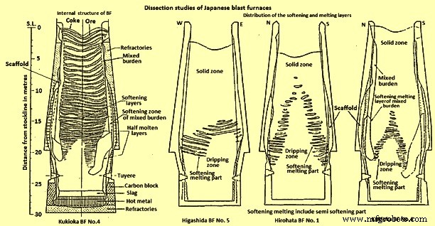
图1日本高炉解剖研究
减少水平 – Hirohata BF no. 各负担层减少程度的研究。 1 和 Kukioka BF no.4 带来了有趣的功能。有趣的特征之一是,在负载到达内聚区之前几乎不会发生还原,其中还原进行得很快。 One of the major problems with water quenching is the possible reoxidation of the burden material during the cooling period and laboratory tests were conducted to determine the extent of reoxidation which might be taking place. One study was made to measure the reoxidation of sinter, in the laboratory, under the same cooling conditions existing during quenching of a BF, using a series of different initial reduction levels. The another study used another technique employing burden materials of various reduction degrees cooled from three different temperatures (400 deg C, 800 deg C and 1000 deg C) at a cooling rate of 200 deg C per hour in a nitrogen (N2) atmosphere. In this study it has been found that although the reduction temperatures and reduction degrees were different, the final reoxidation degree was around constant at 20 % to 25 %, i.e. the reoxidation increased in proportion to the initial reduction degree. At temperatures below 300 deg C, no reoxidation occurred. The result of these experiments is that the reduction levels were required to be increased, for example, from 10 % to 30 % to 15 % to 40 %. These corrected levels were in agreement with the reduction levels found in Russian dissection studies on a N2 quenched furnace.
Temperature profiles – The temperature isotherms within the furnaces were estimated by a combination of several methods. In one method, ‘Tempil’ pellets encased in numerous graphite holders were charged prior to blowing out the furnaces. This technique allowed the estimation of the temperature within the range 200 deg C to 1800 deg C, but one of the problems with this technique was that there was no method of controlling the distribution of the graphite holders within the BF. The other methods employed were measurement of the extent of coke graphitization, thus estimating the temperature between 1200 deg C and 1700 deg C. Measurement of the coke electrical resistance, which allowed temperature estimation between 1100 deg C and 1700 deg C and finally the degree of iron ore fusion was measured to estimate temperatures within the range of 900 deg C to 1400 deg C.
Comparing the isotherms with the distribution of the softening-melting burden layers (Fig 1 and Fig 2), it was found that the cohesive zone exists over a temperature range of around 1100 deg C to 1500 deg C for BFs operating mainly on sinter burdens.
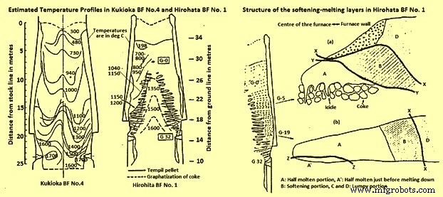
Fig 2 Estimated temperature profiles in Kukioka BF no. 4 and Hirohata BF no. 1 and structural of the softening-melting layers in Hirohata BF no. 1.
Burden layer structure within the cohesive zone – The type of structure of an individual burden layer in the cohesive zone depends upon the position of the layer within the BF. Two layers from Hirohato BF no.1 are shown in Fig 2. Layer G-5 is near the apex of the cohesive zone, while layer G-19 is situated near the base of the cohesive zone. Layer G-5 has four distinct zones, two of which are lumpy or granular portions (C and D). Layer G-19, on the other hand, contains only one lumpy portion, D. Apart from the obvious shape differences between the layers, the other main difference is the replacement of the icicles’ in layer G-5 by a half-molten portion just prior to melting down, A in layer G-19.
As seen earlier a substantial amount of reduction takes place in the cohesive zone and this has been proved by the reduction data obtained for each portion as given in Tab 1, and Tab 2. The figures are on the low side, as reoxidation, caused by the act of water quenching, certainly have taken place. The reason for the high reduction level of portion C is attributed to the slightly lower reduction temperature while in contact with the coke.
| Tab 1 Degree of reduction of the burden materials in the softening-melting layers of Hirohata BF no. 1 | ||||
| Softening-melting layer | Portion* | Reduction degree % | ||
| Sinter | Ore lump | Pellet | ||
| G-5 | A | 65.6 | 65 | 79.3 |
| C | 72.8 | 68.2 | 81.2 | |
| D | 11.5 | 12.3 | 14.6 | |
| G 19 | D | 35.4 | 36.6 | 41.3 |
| * B:Softening portion, C and D:Lumpy portion | ||||
| Tab 2 Degree of reduction of the pellets in the lumpy portion | ||
| Softening-melting layer | Sampling position (distance from the boundary*) (m) | Mean value of the reduction of the sample pellets (%) |
| G3 | 2 | 12.7 |
| 0.2-around 0.3 | 23.1 | |
| G10 | 1 | 14.1 |
| 0.2-around 0.3 | (55)** | |
| G12 | 1.3 | 13.9 |
| 0.9 | 14.3 | |
| 0.5 | 12.3 | |
| * Between the lumpy and softening portions | ||
| ** The value of the reduced pellet being not reoxidized | ||
The thickness of the softening-melting layers in Hirohata BF no. 1 ranged from 400 mm to 500 mm, in the case of the upper layers, to 70 mm – 100 mm for the layers near the base of the cohesive zone. The diminishing thickness is due to compaction, caused by the pressure exerted by the weight of material above the layer and also because of a natural thinning of material due to the increase in furnace diameter as the material descends. In the softening portions iron ore granules were combined in contact with each other. Sinter particles in the layers deformed very little, unlike pellets, which showed signs of deformation.
The process of pellet metallization can take place in one of three modes namely (i) the metallic iron is uniformly distributed within a pellet, (ii) a metallic shell is formed, leaving a wustite core, and (iii) wustite within the pellet reacts to form a slag and moves towards the metallic iron shell, leaving a central cavity. The reason for these three possible modes is not connected with the distribution within the softening-melting layer, but can be due to differences between the pellets or uneven gas flow in the softening-melting layer.
It has been found that the half molten portion consisted of highly compacted metallic iron and a small quantity of slag. Any limestone or olivine present remained unslagged. The icicles extend into the coke voids and consist of a metallic shell with a hollow interior, with small droplets of slag adhering to the iron. The higher the softening-melting layer within the furnace, the greater the length of the icicles, e.g. level G-1 produced some icicles of several hundreds of millimeters in length, while the lower layers produced icicles only 10 to 20 millimeters long.
The structure of the softening-melting layers in Kukioka BF no.4 was basically identical to those described for Hirohata BF no.1, except the thinner burden layers made the structure less distinct and the icicles smaller.
Slag composition changes – The major chemical change of the slag phase in the softening-melting layers is a decrease in the FeO content as the slag trickles down from the melting portion. Although large differences were detected by x-ray microanalyses of slags in portion A, ranging from 2 % to 20 % FeO, depending upon the location, the FeO content of the slag immediately prior to separation from the softening-melting layer was only 2 % to 3 %. The type of slag was not significantly different to that found in the normal sinter product, but in the ore granules a considerable quantity of fayalite was produced. Descent of the slag results in a gradual change in composition. The gradual increase in the CaO/SiO2 ratio is attributed to fluxing with limestone and a drop in the SiO2 content, caused by SiO2 reduction. The rise in Al2O3 is created by the incorporation of coke ash into the descending slag.
Metal composition changes – Considering the changes in metal composition as it descends the furnace; the carbon content of the metal in the half-molten portion of the softening-melting layer is around 0.2 % in the upper part and 0.35 % to 0.57 % in the lower part. The source of C in these half-molten layers is attributed to the carburizing action of the CO, except for the metal in contact with coke. Similar trends are visible in the layers found in Kukioka BF no.4. The rise in the C content of the icicles is attributed to the metal being in direct contact with particles of coke. Two distinct processes have been identified which are operating for the separation of metallic iron from the layers. The first mechanism is via the icicles which form at 1350 deg C to 1400 deg C and drip into the coke bed. Reduction of the iron oxides present in the icicles occurs rapidly to produce metallic iron. The second process occurs in layers in which no icicles form. In this situation, the metallic iron is carburized by the underlying coke until it reaches a C level such that melting can occur at the pertaining temperature. In this case the temperature of meltdown is around 1500 deg C.
The question of the mechanism of silicon pick-up by the metal within the furnace has been the subject of considerable discussion. Studies carried out in the experimental BF at Liege, Belgium fitted with sampling probes have found that the silicon level rise gradually from the melting zone to the hearth, such that 75 % of the final HM silicon is achieved by the time the metal reached the tuyere level. The Japanese dissection studies on the other hand reveal that the silicon level of the metal at the tuyere level is far in excess of that of the tapped HM. An explanation for this discrepancy between the two groups of studies can be that silicon pick-up had occurred during the process of water quenching the Japanese furnaces. During the experiments conducted to determine the probability of silicon pick-up during quenching, it was found that silicon pick-up from any slag present could be a possibility. Hence, this is to be borne in mind when analyzing the Japanese dissection data.
The sulphur (S) level of the metal within the softening-melting region is much higher than the concentration in the tapped HM. In the granular zones very little increase in S level occurs, which can be due to the materials in the softening-melting zone absorbing the S from the ascending gases, rather than a lack of absorption capacity by the burden in the granular zones. The lack of substantial quantities of S in the gas in the stack of the furnace can explain the horizontal profile at temperatures below 800 deg C. Further, as the temperature and slag basicity rise, the distribution of S between the slag and metal increases accordingly. Some idea of how S recirculates within the BF can be seen in Fig 3 in which the circulation of S within Hirohata BF no. 1 is shown.
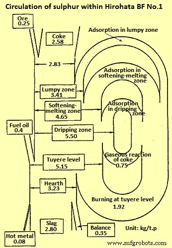
Fig 3 Circulation of sulphur within Hirohata BF no. 1
Size distribution – The change in physical size of the burden components during their descent was determined from the quenched furnace data and one of the major problems with this part of the study was that breakdown of material occurs during the quenching operation. Degradation of sinter reaches a maximum at temperatures of 400 deg C to 600 deg C and increases with the retention time. At levels of reduction in excess of 30 %, very little degradation occurs. Estimation of the cooling pattern of Kokura BF no.2 shows that the burden materials are exposed for a lengthy period of time to conditions which lead to considerable breakdown. The effect of the water quenching operation on the degradation of sinter was calculated. This calculation indicates that the sinter degradation increases with time after blow out and considerable degradation occurs in the region around the middle of the shaft.
Applying this to a centre working furnace (centre working means that the majority of the gas flows up the central axis of the furnace), it has been noticed that the degradation of sinter in the central zone of the furnace, where the reduction degree is high, is mainly caused by the reduction processes during operation. The situation in the peripheral zone is that the reduction degree is low and in this situation the breakdown is mainly caused by the long residence time of materials around 500 deg C during blowing out of the furnace. This was illustrated with the dissection results for the centre working Hirohata BF no.1. Another factor in maintaining the size of the burden materials is that in the central region of Hirohata BF no. 1, cracks if generated fused immediately because of the high temperatures and the rapid reduction taking place. Degradation is generally a problem having maximum concerns with sinters. Examination of the size distribution of pellets revealed that they were hardly pulverized and maintained their original shape.
Influence of gas flow – To further prove that the determination of the shape of the cohesive zone is by the gas flow within the furnace, core samples were taken from the Hirohata BF no.1 and Kukioka BF no.4 and their permeability was determined. Then their permeability was related to gas flow and gas velocity distribution profiles were prepared. These profiles can be directly related to the softening-melting layer distribution. The gas flow in the lower part of the BF is fast, 7 m/sec to 9 m/sec but slows considerably in the softening-melting layers to 2 m/sec to 4 m/sec thus indicating the poor permeability of the softening-melting layers. As the gas ascends the shaft its velocity naturally decreases due to the drop in gas temperature.
Cohesive zone control
It has been shown that the shape of the cohesive zone varies from BF to BF and much attention needs to be given for its control. The control of the cohesive zone is very dependent upon burden distribution. For maximum production, at the expense of fuel rate, a strong centre working profile is to be adopted, but if the fuel rate is to be minimized, then a less centre working practice is to be followed. Indeed, this is very much visible when comparing a strong centre working furnace, like Hirohata BF no.1 with moderate centre working furnace, like Kukioka BF no. 4. This point can be well explained by relating productivity to the height of the cohesive zone above the tuyeres (Fig 4). The higher the position of cohesive zone in the furnace, the greater is the productivity, although at the expense of an increase in fuel rate.
Another point concerning control of the cohesive zone is its effect on the refractory lining. If the wall temperature of the furnace is too high, then refractory wear is appreciable and one can expect a reduced life of the BF. Thus, for maintaining the refractory thickness, it is necessary to control the cohesive zone so that the wall temperatures are maintained at minimum levels.
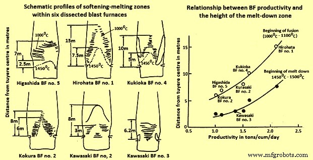
Fig 4 Schematic profiles of softening-melting zones and relationship BF productivity and height of the melt-down zone
Melting processes
The role of S in the melting process is governed by the Fe-S-O phase diagram. There is a necessity of a reaction between solid metallic iron and wustite in the burden with gaseous S, in the ascending gases. These phases react to form a eutectic of chemical composition 24 % S, 9 % O2, and 67 % Fe, having a melting point of 915 deg C. Once formed this liquid gains temperature as it descends the furnace, dissolving solid metallic iron and wustite which cause a change in liquid composition along a path until at certain point, the liquid splits into two conjugate liquid phases. Further increases in the temperature cause first part of the liquid to dissolve more solid iron, moving its composition along a path while the second part of the liquid dissolves more iron oxide and moves along the another composition path. Thus there are two phases (i) a liquid metal phase, and (ii) a liquid slag phase. The presence of silica in the system does not appreciably alter this mechanism. Indeed it moves the miscibility gap. Hence the separation of the nascent liquid into liquid metal and liquid slag phases occur at lower temperatures.
Once formed the two liquids go their own separate ways. The liquid metal dissolving solid iron, C and S become the final metal phase. The slag during its descent dissolves alumina, silica and lime from the coke ash, burden gangue and fluxes to form the final slag phase. A study has also shown that that the presence of hydrogen sulphide, in a CO / N2 gas mixture, lowered the melting point of iron ore sinters and pellets due to the formation of the liquid Fe-S-0 phase.
Alkalis are also thought to be closely associated with the initial melting process in the BF. Study with regards to the distribution of alkali, shows that the alkali is concentrated in the softening-melting layers. The reason for this is that alkali compounds, inherent within the burden and coke charged into the furnace are reduced and at temperatures in excess of 800 deg C to 900 deg C, the alkalis vapourize, as a metallic element or as a cyanide, and are swept into the softening-melting layers where they concentrate . As the softening-melting layers descend the alkali evaporates and continues the cycle.
制造工艺