

使用 ESP8266-01 和 Arduino 的物联网
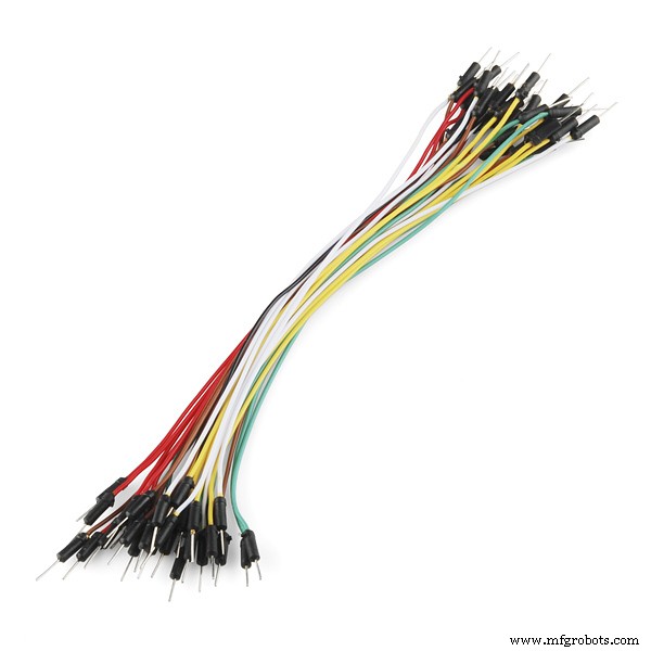
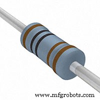
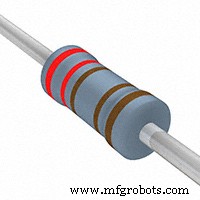
组件和用品
 |
| × | 1 | |||
 |
| × | 1 | |||
 |
| × | 1 | |||
| × | 1 | ||||
 |
| × | 2 | |||
 |
| × | 1 | |||
 |
| × | 1 | |||
 |
| × | 2 | |||
 |
| × | 1 |
必要的工具和机器
| |
| |||
 |
| |||
 |
|
应用和在线服务
| ||||
 |
| |||
|
关于这个项目
简介
今天,我们将构建一个连接到互联网的设备,并允许用户通过 wifi 远程控制他/她的家。我们将使用带有 ESP8266-01 wifi 模块的 Arduino 板(任何型号都可以很好地完成工作)来制作此设备。让我们开始吧!
什么是智能家居?
工作场景
控制面板
我们将构建一个简单的网页,作为用户的控制面板,允许他控制连接到我们系统的任何家用电器。要构建我们将使用的网页:
- HTML
- CSS
- Jquery
嵌入式硬件
网页向 ESP8266-01 发送一些命令,ESP8266-01 用作连接到 Arduino 板的网络服务器。根据传入的数据,Arduino 板将执行一些操作,例如打开灯泡、关闭电视,在这部分中,我们将使用:
- 阿杜诺
- ESP8266-01
ESP8266-01 入门
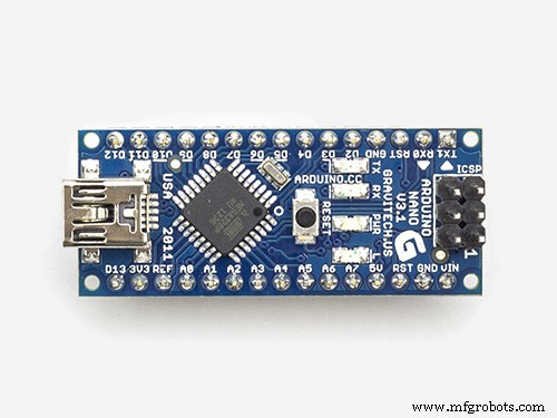
正如我们之前所说,我们需要将 Arduino 板连接到互联网,但我们今天使用的 Arduino Nano 版本没有该功能。因此,我们将使用 ESP8266-01 wifi 模块将 wifi 功能添加到我们的微型 Arduino 板上。
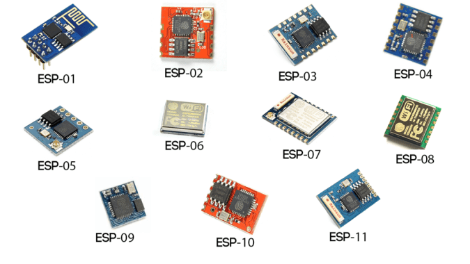
ESP wifi 模块型号很多,我应该选择哪一个?!嗯,几乎所有 ESP 系列 wifi 模块都可以很好地完成这项工作,但每个模块都有自己的功能和规格。我鼓励您查看每一种规格和功能,以选择最适合您需求的一种。
根据我的需求,我发现 ESP8266-01 是最合适的,原因有很多。它在创客社区非常有名。因此,它有一个非常可靠的在线社区,您可以通过这个很棒的小模块找到几乎所有问题或问题的答案。此外,它的价格非常便宜(约 1.5 美元)。
此外,它非常容易与 Arduino 板一起使用,因为它是一个串行 wifi 模块,它可以通过串行通信与 Arduino 板进行通信。它有一个内置的微控制器,这意味着您可以将它用作一个独立的微控制器和 wifi 模块,这是一个非常酷的组合。它内置了两个 GPIO。只需 1.5 美元,您就可以获得所有这些非常酷的功能,实际上。让我们仔细看看这个模块。
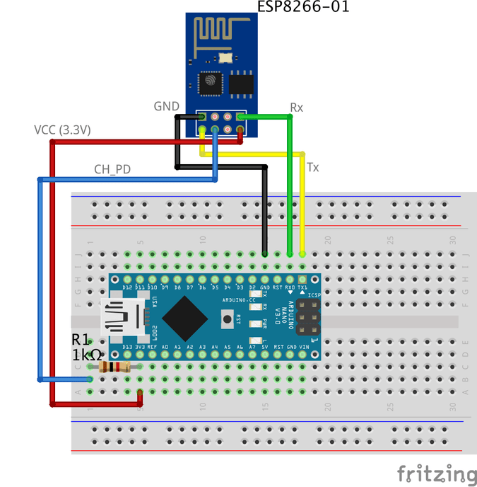
ESP8266-01 引脚排列
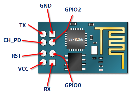
- VCC: 连接到+3.3V 电源。 请勿将其与 5V 电源连接,否则会损坏 .
- 地线: -ve 引脚,将其连接到电路的地。
- CH_PD: 芯片使能引脚 – 高电平有效。将其连接到逻辑值 HIGH 以允许模块启动。
- RST: 芯片复位引脚——低电平有效,当它拉低时,它会复位模块。
- GPIO0、GPIO2: 通用输入/输出引脚。
- 发送: 连接到微控制器(Arduino)的 Rx 以建立串行通信。
- 接收: 连接到微控制器(Arduino)的 Tx 以建立串行通信。
ESP8266-01 配置
正如我们之前所说,ESP8266-01 模块通过串行通信与 Arduino 板通信,这意味着我们需要将其与 Arduino 的串行引脚 0、1(Tx、Rx)连接。但这里的问题是这些引脚会很忙,因为我们将在 ESP8266-01 旁边使用 Arduino 串行监视器进行调试。因此,我们需要找到另外两个串行通信引脚,以便与 ESP8266-01 一起使用。
幸运的是,Arduino 让这一切变得简单。有一个名为“SoftwareSerial”的库,其开发用于允许在 Arduino 的其他数字引脚上进行串行通信,使用软件来复制功能。例如,通过使用这个库,我可以将引脚 2、3(软件串行)与引脚 0、1(硬件串行)一起设置为 Rx 和 Tx。
“软件序列” 只要传输速度小于 19、200 波特,库就可以很好地工作。但是,这里有一个小问题! ESP8266-01 wifi 模块来自工厂,编程为以 115、200 波特的速度进行通信,这在“SoftwareSerial”库中很难进行通信。因此,我们需要重新编程我们的 wifi 模块以将通信速度设置为 9600 波特,这与“SoftwareSerial”库配合得非常好。为此,我们将使用一些“AT 命令”。
更改 ESP8266-01 通信速度
第一步:上传一个空程序到Arduino板
在这一步,我们将一个空代码上传到 Arduino 板。只是为了确保 Arduino 板没有在后台执行任何操作。
第二步:用Arduino板连接ESP8266-01
要重新配置 ESP8266-01 并更改通信速度(波特率),我们使用 AT 命令。简单来说,AT指令就是一些用来控制调制解调器、手机、蓝牙模块、wifi模块、GSM模块的指令。
通过这些命令,我们可以获得有关我们的手机或 GSM 模块的基本信息,例如制造商名称、型号、IMEI 等。“AT”是“ATtention”的缩写,它被称为 AT 命令,因为每个命令都开始与“AT”。 “AT”前缀不是命令本身的一部分,它只是告诉模块命令的开始。
一些重要的 AT 命令
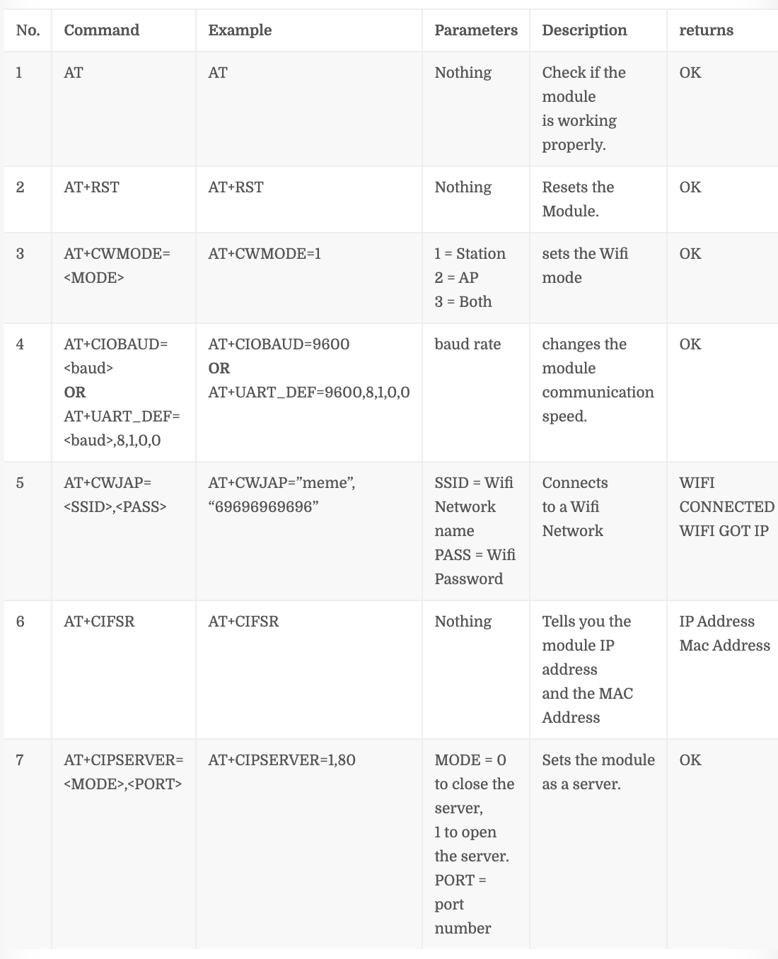
命令编号“4” 取决于您的 ESP8266-01 固件版本,如果此命令对您不起作用 AT+CIOBAUD= 试试这个AT+UART_DEF=
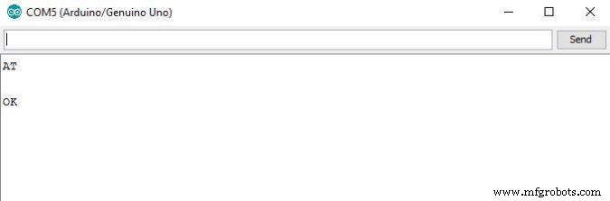
步骤 1:打开串行监视器
第 2 步:将通信速度设置为 115、200 波特

正如我们之前所说的,ESP 来自制造商,它被编程为以 115、200 波特的速度进行通信。所以我们需要将Arduino通信速度设置为115, 200 也是第一次,只有这样我们以后才会改变。另外,您应该选择“Both NL &CR” .
第 3 步:发送“AT”并等待响应以确保 ESP 模块听到您的声音。
第 4 步:现在,更改 ESP8266-01 的通信速度
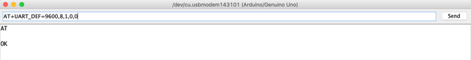
我的 ESP8266-01 模块加载固件是 1.6。和这个命令 AT+UART_DEF= 对我来说效果很好。如果它不适合你,试试这个 AT+CIOBAUD= .如果它响应 “OK” 现在您的 ESP 模块通信波特率从 115, 200 更改 波特率 9600 波特。恭喜!
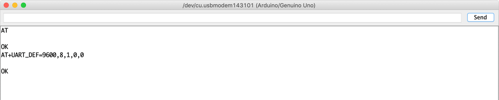
让我们把串口监听的通讯速度改回9600,再发送“AT”看看ESP模块在新的Speed(9600)下能不能听到我们的声音。
看!它正在工作。 ESP8266-01 现在可以以 9600 波特率而不是 115、200 波特率与 Arduino 板通信。
现在,让我们尝试连接 Wifi 网络
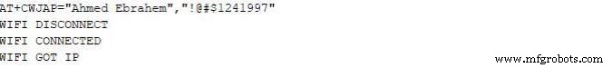
按回车键后,ESP8266-01 将搜索此网络并与之连接。如果进程成功,它会返回这个
WIFI 已连接
WIFI GOT IP
至此,我们成功将ESP8266-01的通讯速度从115、200波特改为9600波特。现在,我们需要构建用户将用来控制他的家用电器的控制面板(网页)。那么,让我们构建它吧!
什么是互联网?
实际上,互联网是埋在地下的电线,它可以是光纤、铜线,甚至是卫星,但互联网只是一根电线。连接到该电线的任何两台计算机都可以进行通信。如果计算机是直接连接 到那条线,它被称为服务器 如果它没有直接连接到那条线,则称为 客户端 .
服务器: 是一台运行特定操作系统的特殊计算机,如 Apache,这台特殊计算机在其磁盘驱动器上保存了一些网页、文件、数据库。任何连接到互联网的服务器都有一个唯一的 IP 地址,例如 172.217.171.228 ,IP地址就像一个电话号码,可以帮助人们轻松找到对方。因为那个 IP 地址对于人类来说不是很容易记住。所以,我们只是给它起了个名字 google.com (域名)。
客户: 它是一台像你我每天都在使用的计算机,它通过互联网服务提供商 (ISP) 间接连接到互联网,并且它还有一个唯一的 IP 地址。
工作场景
简单地说,它以从 google chrome、firefox 等网络浏览器(客户端)发送的请求开始,以从网络服务器收到的响应结束。
您在计算机(客户端)的浏览器中输入网站 URL makesomestuff.org,然后该浏览器向托管该网站的网络服务器发送请求,然后网络服务器将包含 HTML 页面或任何其他文档格式的响应返回给浏览器以显示
没错,这就是我们今天在项目中需要做的事情。我们需要从网络浏览器(客户端)向 ESP8266-01(网络服务器)发送请求,它们都连接到同一个本地网络。此请求包含一些数据,这些数据告诉 Arduino 如何打开或关闭灯泡。那么,让我们构建网页吧!
构建网页
为了构建我们的网页,我们必须处理 HTML、CSS、Javascript。如果你以前从未听说过这些名字,别担心我知道了。
HTML: 代表“超文本标记语言”,我们用它来构建任何网页主要结构。就像添加一些按钮、图像、段落、标题、表格和更多元素。它由一系列元素组成,这些元素告诉浏览器如何显示网页内容。这些元素由称为标签的东西表示。

CSS: 它代表级联样式表。构建网页主结构后,您需要使该结构看起来不错,这里来了 CSS 来制作一些样式。它是一种描述 HTML 元素样式的语言。它由一些选择器和减速块组成。

Javascript: 它是一种编程语言,我们将使用它来使网页更具交互性,例如添加一些动画、地图,并允许我们在网页上制作一些复杂的东西。主要是今天我们将使用它从客户端(网络浏览器)向网络服务器(ESP8266-01)发送 HTTP 请求,以执行一些操作,例如打开或关闭灯泡。

构建网页结构
为了轻松理解接下来的解释,我推荐阅读这篇很酷的 HTML 介绍 .
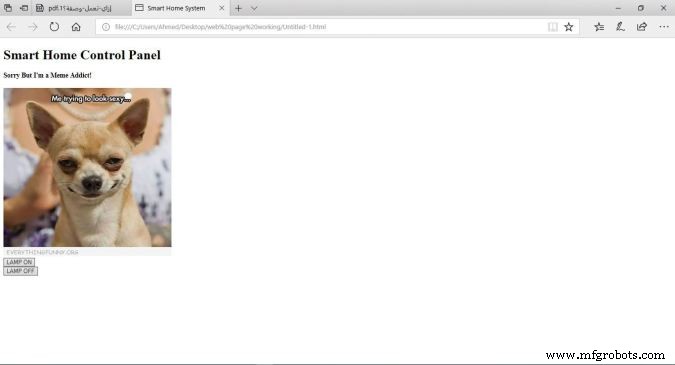
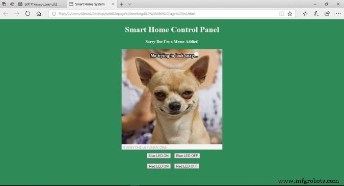
正如我们所看到的,我们的控制面板非常简单,它包含两个标题,每个标题都有不同的大小、一个图像和两个按钮,一个用于打开 LED,第二个用于关闭。
代码
智能家居系统 智能家居控制面板
对不起我是 Meme 迷!

代码说明
- : 声明定义此文档为 HMTL5 文档。
- : HTML 页面的根元素。
- : 元素包含有关页面的元信息。
- <标题>: 元素指定文档的标题。此标题显示在网页浏览器选项卡上。
- <正文>: 元素包含可见的网页内容。
:
element 定义了一个大元素。:
element 定义了一个较小的标题。当标题值减小时,字体减小。: 元素向网页添加图像。您要显示的图像应该在同一个项目文件夹中。
: 将光标移到新行。- <按钮>: element 为页面内容添加一个按钮。
每个按钮都是我们网页中非常重要的两个属性id , 和 class 属性。我们将在Jquery代码解释中讨论为什么我们将这两个值分配给按钮。
网页样式
为了轻松理解接下来的解释,我推荐阅读这篇很酷的 CSS 介绍 .
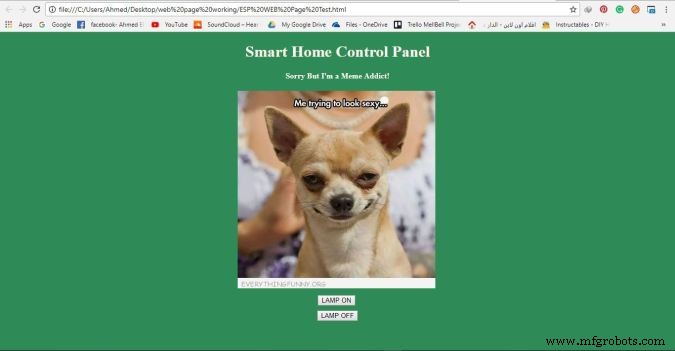
现在,网页看起来更好(不是太多 xD)我们给它一个凉爽的绿色背景颜色,我们使页面内容居中对齐,我们更改标题字体颜色和字体系列,使网页更加生动。我们使用 CSS 来完成所有这些样式设置。
代码
智能家居系统 智能家居控制面板
对不起,我是个迷因迷!
代码说明
我们添加了几行代码,使我们的网页看起来更漂亮。我们添加了 style="background-color:seagreen; color:seashell; text-align:center;" 正文 标签 使所有网页内容位于页面中央 并将背景颜色设置为海绿色 还要将字体颜色设置为贝壳 .
此外,我们添加了 style="margin:10px;" 在两个 button 标签内 在每个按钮的四个边周围设置 10 个像素的边距。
向网络服务器发送请求
为了更容易地理解接下来的解释,我推荐阅读这个很酷的 Jquery 介绍 。
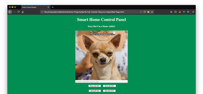
现在,在构建我们的网页结构和样式之后,我们需要向我们之前在网页中添加的两个按钮添加一些功能。我们需要当用户点击“LAMP ON”按钮时,他/她的浏览器向服务器(ESP8266-01)发送一个包含一些独特数据的请求,这个独特的数据告诉Arduino打开灯。与第二个按钮“LAMP OFF”相同,当用户点击它时,浏览器会向服务器(ESP8266-01)发送一个包含一些独特数据的请求,这个独特的数据告诉 Arduino 关闭灯。来看看代码吧。
智能家居系统 智能家居控制面板
对不起,我是个迷因迷!
代码说明
第一件事 首先,我们需要在我们的代码中导入 Jquery 库。所以,我们在 head 标签中添加了这一行 .
所有的魔法都发生在这个有趣的部分。
Smart Home Control Panel
Sorry But I'm a Meme Addict!
How It Works
Just like the last trial, You upload the Arduino code to the board (if not uploaded yet) and open the serial monitor and make sure that your ESP module is connected successfully to your access point and got an IP and MAC address.
Then open your fancy web page and start controlling your stuff 😉
Make it more professional!
What about transferring our breadboard circuit to a professional printed circuit board (PCB) to make our project more rigid and solid, I designed the project circuit using Autodesk Eagle software. all the PCB files are open-source you can access it from this link:https://www.pcbway.com/project/shareproject/IoT_Using_Arduino_and_ESP8266_01.html
Because we love open source 😉
You can order your own PCB From PCBWay company these guys have a very good reputation in this field and they ship to more than 170 countries around the world with reasonable prices. all you have to do is to open the project PCB files link and press “Add to cart”. That’s it!
Troubleshooting
if your ESP Module is successfully connected to your access point but there is no action happens when you click the web page buttons
- make sure that you are sending the request from your web browser from port 80(HTTP). example:
$.get("http://192.168.1.4:80/"
- make sure that your PC or Laptop and the ESP module is connected to the same Access point.
- In Jquery code, make sure that you wrote the right ESP module IP address.
- Make sure that you are connecting the load at Arduino digital pins 11 and 12.
- Don’t forget to save the Web page code file after any change or modification, and reload the web page in the web browser after any code modification to take effect.
Final
We are done! in today’s tutorial, we learned how to build a simple web page using HTML, CSS, and jquery. Also, we learned how to control an AC load wirelessly from a web-based control panel, and how to use the awesome ESP8266-01 Wifi module with the Arduino board.
you wanna see more Tutorials and open source projects you can also visit my blog www.makesomestuff.org
Lastly, if you have any questions drop it in the comments section below, I will be more than happy to hear from you 😉
代码
- Web Page
- Final Arduino Code
Web PageHTML
Smart Home System Smart Home Control Panel
Sorry But I'm a Meme Addict!
Final Arduino CodeArduino
#include//including the SoftwareSerial library will allow you to use the pin no. 2,3 as Rx, Tx.SoftwareSerial esp8266(2,3); //set the Rx ==> Pin 2; TX ==> Pin3.#define serialCommunicationSpeed 9600 // <=========define a constant named "serialCommunicationSpeed" with a value 9600. it referes to the Software and hardware serial communication speed(baud rate).#define DEBUG true //make a constant named "DEBUG" and it's value true. we will use it later.int redLED =12; //assign a variable named "redLED" with an integer value 12, it refers to the pin which the red LED is connected on.int blueLED =11; //assign a variable named "blueLED" with an integer value 11, it refers to the pin which the blue LED is connected on.void setup(){ pinMode(redLED,OUTPUT); //set the pin number 12 as an output pin. pinMode(blueLED,OUTPUT); //set the pin number 11 as an output pin. digitalWrite(redLED,LOW); //turn the red LED off at the beginning of the program. digitalWrite(blueLED,HIGH); //turn the blue LED on at the beginning of the program. Serial.begin(serialCommunicationSpeed); //begin the Hardware serial communication (0, 1) at speed 9600. esp8266.begin(serialCommunicationSpeed); //begin the software serial communication (2, 3) at speed 9600. InitWifiModule(); //call this user-defined function "InitWifiModule()" to initialize a communication between the ESP8266 and your access point (Home Router or even your mobile hotspot). digitalWrite(blueLED,LOW); //after finishing the initialization successfully, turn off the blue LED (just an indicator).}void loop() //our main program, some fun are about to start){ if(esp8266.available()) //if there's any data received and stored in the serial receive buffer, go and excute the if-condition body. If not, dont excute the if-condition body at all. { if(esp8266.find("+IPD,")) //search for the "+IPD," string in the incoming data. if it exists the ".find()" returns true and if not it returns false. { delay(1000); //wait 1 second to fill up the buffer with the data. int connectionId =esp8266.read()-48; //Subtract 48 because the read() function returns the ASCII decimal value. And 0 (the first decimal number) starts at 48. We use it to convert from ASCI decimal value to a character value. esp8266.find("pin="); //Advance the cursor to the "pin=" part in the request header to read the incoming bytes after the "pin=" part which is the pinNumer and it's state. int pinNumber =(esp8266.read()-48)*10; //read the first Byte from the Arduino input buffer(i.e. if the pin 12 then the 1st number is 1) then multiply this number by 10. So, the final value of the "pinNumber" variable will be 10. pinNumber =pinNumber + (esp8266.read()-48); //read the second Byte from the Arduino input buffer(i.e. if the pin number is 12 then the 2nd number is 2) then add this number to the first number. So, the final value of the "pinNumber" variable will be 12. int statusLed =(esp8266.read()-48); //read the third byte from the Arduino input buffer. then save it inside the "statusLed" variable. At any case, it will be 1 or 0. digitalWrite(pinNumber, statusLed); //then turn the LED at "pinNumber" on or off depending on the "statusLed" variable value. Serial.println(connectionId); //print the "connectionId" value on the serial monitor for debugging purposes. Serial.print(pinNumber); //print the "pinNumber" value on the serial monitor for debugging purposes. Serial.print(" "); //print some spaces on the serial monitor to make it more readable. Serial.println(statusLed); //print the "statusLed" value on the serial monitor for debugging purposes. String closeCommand ="AT+CIPCLOSE="; //close the TCP/IP connection. closeCommand+=connectionId; //append the "connectionId" value to the string. closeCommand+="\r\n"; //append the "\r\n" to the string. it simulates the keyboard enter press. sendData(closeCommand,1000,DEBUG); //then send this command to the ESP8266 module to excute it. } }}/******************************************************************************************************************************************************************************************* Name:sendData* Description:this Function regulates how the AT Commands will ge sent to the ESP8266.* * Params:command - the AT Command to send * - timeout - the time to wait for a response * - debug - print to Serial window?(true =yes, false =no)* * Returns:The response from the esp8266 (if there is a reponse)*/String sendData(String command, const int timeout, boolean debug){ String response =""; //initialize a String variable named "response". we will use it later. esp8266.print(command); //send the AT command to the esp8266 (from ARDUINO to ESP8266). long int time =millis(); //get the operating time at this specific moment and save it inside the "time" variable. while( (time+timeout)> millis()) //excute only whitin 1 second. { while(esp8266.available()) //is there any response came from the ESP8266 and saved in the Arduino input buffer? { char c =esp8266.read(); //if yes, read the next character from the input buffer and save it in the "response" String variable. response+=c; //append the next character to the response variabl. at the end we will get a string(array of characters) contains the response. } } if(debug) //if the "debug" variable value is TRUE, print the response on the Serial monitor. { Serial.print(response); } return response; //return the String response.}/******************************************************************************************************************************************************************************************* Name:InitWifiModule* Description:this Function gives the commands that we need to send to the sendData() function to send it.* * Params:Nothing.* * Returns:Nothing (void).*/void InitWifiModule(){ sendData("AT+RST\r\n", 2000, DEBUG); //reset the ESP8266 module. //delay(1000); sendData("AT+CWJAP=\"Decoder\",\"1241997GoGo\"\r\n", 2000, DEBUG); //connect to the WiFi network. delay (3000); sendData("AT+CWMODE=1\r\n", 1500, DEBUG); //set the ESP8266 WiFi mode to station mode. delay (1500); sendData("AT+CIFSR\r\n", 1500, DEBUG); //Show IP Address, and the MAC Address. delay (1500); sendData("AT+CIPMUX=1\r\n", 1500, DEBUG); //Multiple conections. delay (1500); sendData("AT+CIPSERVER=1,80\r\n", 1500, DEBUG); //start the communication at port 80, port 80 used to communicate with the web servers through the http requests.}
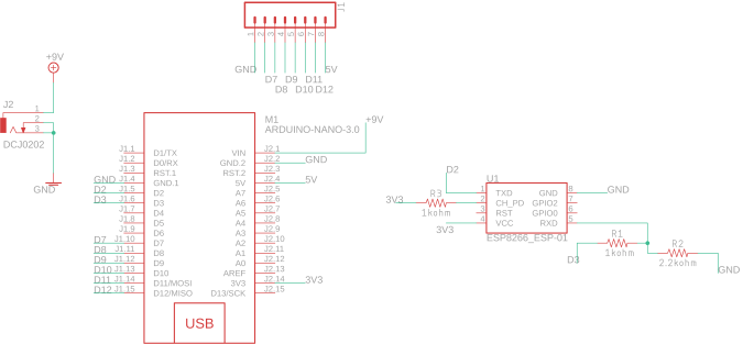
示意图
制造工艺
- TinyML-Language Detector-基于 Edge Impulse &Arduino
- Arduino Gyroscope Game with MPU-6050
- Arduino 数字骰子
- 使用 ARDUINO 的超声波悬浮机器
- 使用 Arduino 和智能手机的 DIY 电压表
- 使用物联网的心率监测器
- IOT - 使用 ESP8266、Arduino 和超声波传感器的智能罐
- Sonar 使用 arduino 并在处理 IDE 上显示
- 使用 Bolt 和 Arduino 控制 LED 亮度
- 使用 Alexa 和 Arduino IoT Cloud 完全控制您的电视
- 使用 Arduino 和 RDA8057M 的 FM 收音机
- NeoMatrix Arduino Pong